Article

Experimental Study on the Flow Field, Force, and Moment Measurements of Submarines with Different Stern Control Surfaces

1
College of Ship and Ocean, Naval University of Engineering, Wuhan 430033, China
2
Jiangnan Shipyard Co., Ltd., Shanghai 201913, China
*
Author to whom correspondence should be addressed.
J. Mar. Sci. Eng. 2023, 11(11), 2091; https://doi.org/10.3390/jmse11112091
Submission received: 6 September 2023 / Revised: 24 October 2023 / Accepted: 25 October 2023 / Published: 31 October 2023
(This article belongs to the Special Issue Ship Structures II)

Abstract

:
Flow field performance tests of submarine models with cross-rudder and X-rudder stern control surfaces were conducted to study X-rudders’ performance in non-uniform flow fields. The tests compared performance parameters such as resistance, lateral steering force, yaw moment, stern velocity field, and flow field inhomogeneity coefficient under low- and high-speed conditions. The test results show that, at low speed, the resistance of the X-rudder submarine is smaller than that of the cross-rudder one at the same rudder angle. In contrast, at high speed, the resistance of the cross-rudder submarine is smaller than that of the X-rudder submarine. Under low- and high-speed conditions, the X-rudder’s lateral steering force and yaw moment are larger than those of the cross rudder at the same rudder angle. The superiority of the maneuverability of the X-rudder becomes more apparent with increasing rudder angle. At a rudder angle of 10°, the X-rudder’s lateral steering force and yaw moment are about two times larger than the cross rudder’s. In the small-radius area of the propeller plane, the inhomogeneity coefficient of the X-rudder is generally smaller than that of the cross rudder. This is probably because the cross-rudder stern control surfaces have fixed stabilizers with flaps, and the X-rudder stern control surfaces are all-moving, with a small fixed part next to the submarine. This test provides a reference for designing the stern control surface of low-noise submarines.

1. Introduction

The stern control surface (SCS) of submarines is one of the main factors responsible for the inhomogeneity of the wake flow field. It has been reported that improving the homogeneity of the submarine wake field can reduce its radiated noise to a certain extent [1]. Therefore, improving the quality of the submarine wake field by optimizing the layout and structure of the SCSs is an important research direction which is indispensably linked to the design of submarine vibration and noise reduction strategies. Research on submarine wake field characteristics concerns a comprehensive assessment of existing submarines and new technical approaches for developing future submarine SCSs [2,3,4].
In the 1960s, the U.S. installed X-rudder control surfaces on the high-speed test submarine “Albacore” [5]; these were arranged in a 45° cross-section with the longitudinal section of the hull in the circumferential direction. The four individual rudders of the X-rudder were designed as full-motion rudders. The test results revealed that the maneuverability and emergency maneuverability of the X-rudder SCS far exceeded those of any previously tested SCSs [6]. Due to the complexity of the X-rudder maneuvering system, the U.S. did not implement it in practice at that time. Sweden was the first to apply the X-rudder to the Hulmen class submarines, aiming to protect the integrity of the important stern appendages during navigation in shallow water. In 2019, the U.S. reported that in the SSBN-826 class ballistic missile submarine program, where the Columbia class nuclear submarine was a replacement for the Ohio class nuclear submarine, the X-rudder design would be used [7], indicating the recognition of the excellent maneuvering performance of the X-rudder by the U.S. Navy.
In recent decades, researchers from all around the world have focused on the hydrodynamics and maneuverability of the X-rudder SCSs. For example, between 1987 and 1988, Mackay [8], of Defence Research and Development Canada, compiled wind tunnel model test data on the cross-rudder and the X-rudder SCSs and demonstrated that the stall angle in the horizontal plane of the X-rudder was higher compared with that of the cross rudder. Furthermore, the rudder efficiency of the X-rudder comprising four rudders simultaneously was better than that of the cross rudder. Broglia et al. [9,10] of Centro Nazionale delle Ricerche, Italy, conducted a preliminary study on the maneuverability of the X-rudder and the cross-rudder submarines through EFD and computational fluid dynamics (CFD) methods. Zaghi et al. and Dubbioso et al. [11,12], of the Swedish Defense Research Agency, performed preliminary studies on the maneuverability and hydrodynamic derivatives of X-rudder and cross-rudder submarines based on the CFD method. Their results showed that, due to its larger lateral projection area, the maneuverability of the X-rudder was better than that of the cross rudder. In addition, their data revealed that the X-rudder has significantly better yawing performance than the cross rudder because the X-rudder is a fully moving rudder with an increased effective rudder area. Suastika et al. [13] of Department of Naval Architecture, Indonesia, studied the gyration performance of the cross rudder and the X-rudder based on the CFD method and found that the X-rudder has a smaller gyration radius.
Chinese scholars have also conducted basic research on the theory of the X-rudder. In 1991, Feng [14] analysed the Swedish submarine X-rudder device and its application. In 1995, Shi [15] investigated the development, layout, steering mode, and maneuvering characteristics of the X-rudder SCS. In 2004, Zhang et al. [16] compared X-rudders and the cross rudders with unequal rudder angles and studied the effect of the flow field on the hydrodynamic forces. In 2007, Luan and Lin [17] determined the equivalence between the maneuvering force of the X-rudders and the cross rudders from the perspective of submarine X-rudder design and analysed the relationship between submarine motion and maneuvering performance. In 2008, Zhao et al. [18] elaborated on the structural form of the submersible stabilizer wing and determined the main factors that should be taken into consideration when designing the stabilizer wing. In the period of 2003–2008, in order to maximize the rudder effect and improve the maneuvering performance of the X-rudder, Hu et al. [19,20,21,22] established a mathematical model for the equivalent rudder angle conversion between the X-rudder and the cross rudder, proposed the design concept of an equivalent rudder angle conversion device of the X-rudder and the cross rudder, and conducted simulations for an example submarine to verify the concept. In 2017, Zhang et al. [23] studied a Darpa Suboff submarine with either a cross rudder or an X-rudder installed and simulated two submarine motion states (straight incident flow in the horizontal plane and variable angle of attack in the vertical plane) using the CFD method. Their results showed that the hydrodynamic performance of the X-rudder was better than that of the cross rudder. In 2018, Jiao et al. [24] investigated the arrangement of X-shaped rudders in the circumferential direction using angles of 20°, 30°, 45°, and 60° by analyzing the hydrodynamic performance of four different submarines; it was concluded that the hydrodynamic performance of the 45° X-rudder submarine was superior. In 2020, Chen et al. [25] compared the hydrodynamic characteristics of cross-rudder and the X-rudder submarines by taking the pumping effect of the propeller into consideration.
The above literature review suggests that most of the research on X-rudders has been primarily focused on theoretical and numerical simulation methods. Regarding experimental research on the X-rudder, relevant published information is relatively scarce. On the one hand, the manipulation of the X-rudders poses higher requirements on the control system [26,27,28,29]; on the other hand, when using Particle Image Velocity measurements, the diffuse reflection on the rudder surface causes interference with the incident laser sheet [30,31], leading to a difficulty in measuring the flow field on the submarine SCS. The current lack of sufficient experimental measurement data for the validation of theoretical and simulation results of the X-rudder flow field restricts the further development of such theoretical and numerical methods. To this end, this paper conducts a comparative study on the flow field characteristics of different SCSs, i.e., the cross rudder and the X-rudder, by means of experiments, focusing on key parameters such as submarine resistance, lateral steering force, yaw moment, propeller plane velocity field, and heterogeneity. Finally, the differences between the experimental results of the cross-rudder and the X-rudder flow fields are compared.

2. Cross-Rudder and X-Rudder Submarine Flow Field Test Verification

2.1. Test Object

In this case, the test object is a certain type of submarine model equipped with either a cross rudder or a matching X-rudder, which are presented in Figure 1 and Figure 2, respectively.
The design idea of the X-rudder is to transform the cross rudder with a stabilizer wing into a full-motion X-rudder without changing the rudder area, i.e., by ensuring that the area of the X-rudder SCS is almost equal to that of the original cross-rudder SCS. At the same time, the rudder stock position is kept the same as that of the original vertical rotation cross rudder; that is, the distance between the rudder and the hydrodynamic center is kept approximately the same. In the case of the X-empennage, the same SCSs serve as both hydroplanes and rudders depending on the control mode. The two types of SCSs are exhibited in Figure 3 and Figure 4.
In the test design, a benchmark was deployed: when the rudder angle was 0°, the sum of the areas of the rudder and the stabilizer wing of the two SCSs were equal, so as to ensure that the hydrodynamic performance of the two SCSs were equivalent when the rudder angle was 0°. Some dimensional details of the SCSs are shown in Table 1.
The submarine has enclosures and forward hydrofoils at the front. The average chord length of the forward hydrofoil is 0.08 L, and the average span of the forward hydrofoil is 0.16 L. The distance between the leading edge of the forward hydrofoil and the bow is 0.21 L, and the distance between the trailing edge and the forward hydrofoil from the SCSs is 0.62 L. The L in this paper represents the length of the submarine.
The test is mainly concerned with motions within the horizontal plane under straight incident flow, and consequently only yawing forces and moments are investigated. Regarding a cross rudder, only the vertical rudders can perform a steering action, however, in the case of an X-rudder all four rudders must be activated simultaneously. To facilitate the description of the two steering methods for the SCS, the steering directions of the cross rudder and the X-rudder are illustrated in Figure 5. If the two upper rudders of an X-rudder rotate in counterclockwise direction and the two lower rudders in clockwise direction with respect to an axis pointing downstream, the submarine turns right. In this test, the rudder angle of the X-rudder was defined as the same angle in all planes.

2.2. Coordinate System

In order to accurately describe the test conditions, the coordinate system shown in Figure 6 was established, with the x-axis coinciding with the center axis of the submarine and pointing downstream, i.e., towards the stern, the positive direction of the y-axis points to the starboard side of the submarine, and the positive direction of the z-axis pointing upward based on the right-hand rule.

2.3. Test Description

This test was conducted in a ship model pool laboratory. In order to minimise the effects of any currents caused by the submarine’s movements, sufficient time was allowed between the two tests. The main tests carried out were as follows:
(1)
Resistance measurement
The submarine was operated at low speed (Vlow) and high speed (Vhigh), and the type of SCS (cross rudder and X-rudder) and the rudder angle (0°, 2°, 5°, 10°) were changed alternately to determine the resistance of the submarine under different operating conditions.
(2)
Lateral steering force and yaw moment measurement
Under the conditions of Vlow and Vhigh, the type of SCS (cross rudder and X-rudder) and the rudder angle (0°, 2°, 5°, 10°) were changed to determine the lateral steering force and yaw moment under different conditions.
(3)
Velocity field measurement in the propeller plane
Under the conditions of Vlow and Vhigh, the type of SCS (cross rudder and X-rudder) and the rudder angle (0°, 2°, 5°, 10°) were changed to determine the axial velocity distribution at different radii of the propeller plane and quantify the inhomogeneity coefficient.
The tests in this paper were all done at 0° attack angle and 0° drift angle.

2.4. Test Environment

The tests were conducted in a model towing tank (Figure 7), which was 108 m long, 7 m wide, and 3.5 m deep. The water depth could be arbitrarily selected according to the test requirements, and the trailer work frame could be lifted vertically to facilitate different deep and shallow water test requirements (Figure 8). In general, the pool is a large deep-and-shallow dual-use model test pool, its water surface area is large, and experimental research on large ship modelling tests can be performed.

2.5. Test Equipment

The maximum speed of the trailer was 4.5 m/s and the steady speed range was 0.1~4 m/s; the maximum average acceleration a+ was 0.09 g; the maximum average deceleration a− was 0.15 g. In order to keep the model test in a turbulent state, a stimulation wire was installed 5%L from the bow of the submarine, where the diameter of the stimulation wire was 1 mm. A computer-assisted closed-loop system automatically controlled its speed with a steady speed accuracy of 1‰. The water temperature measuring device was a high-precision thermometer with a range of 0~100 °C and an accuracy of 0.1 °C. A six-component force sensor was used to measure the resistance, lateral steering force, and yaw moment of the submarine and the SCS, and a DH-5922 signal test and analysis system was utilized for signal analysis and data acquisition (range of ±20 mV to ±20 V; 8 channels; accuracy of 16 bit D/A). A Stereo Particle Image Velocimetry (PIV) test system was used to measure the propeller plane speed of the submarine with different SCSs (Figure 9 and Figure 10). The Stereo-PIV test system can capture the three-dimensional (3D) non-constant flow field within a measurement area of 200 mm × 200 mm and with a spatial resolution of one millimeter. The specific parameters of the PIV measurement system equipment are a maximum CCD resolution of 2048 × 2048 pixels, maximum laser pulse energy of 1200 mJ, laser beam duration of 4 ns, laser wavelength range of 532 nm~1064 nm, and sheet light thickness of 0.6 mm, and polyamide particles were used as PIV tracer particles.
The lateral steering force and lateral moment of the submarine were measured by a strain gauge balance and a six-component force sensor, as shown in Figure 11 and Figure 12. The balance and sensor were made of stainless steel, the range of the sensor’s three-direction force was 0–500 N, the range of the three-direction moment was 0–20 Nm, and the accuracy was ±0.2%.

PIV Speed Measurement Principle

The 2D3C Stereo-PIV measurement system utilized in this experiment consisted of a modular combination of a fully submersible mine-body, a streamlined wing mount, a laser system, a control and acquisition system, and a particle dispersal system. The specific mine-body arrangement is displayed in Figure 13.
In Figure 13, A is the laser sheet light formed by the line laser passing through the column mirror, B is the laser total reflector compartment, C is the laser column mirror compartment, D is the laser guide arm, E is the hydrodynamic streamline support arm, F is the flow field measurement range area, G is the camera reflector compartment, H is the water environment opening window, I is a 50 mm f/1.8 Canon lens, J is a platform with a rotation function to achieve the Scheimpflug state, K is the camera connection cable, L is the camera cable guide arm, M is an 85 mm f/1.8 Canon lens, and N is the FlowSense 4M Mk II 12-bit precision CCD camera. The reflector angles of the reflector compartment of Cameras 1 and 2 are 56° and 19°, respectively, the angle between the axis of Camera 1 and the image line of sight is 68°, and that between the axis of Camera 2 and the image line of sight is 38°.
The Stereo-PIV analysis process is mainly as follows: over one entire test run, Cameras 1 and 2 capture 200 pairs of particle images, and the following operations are performed on the images obtained by the two cameras: (1) the environmental background of the particle images is extracted, i.e., the minimum pixel value of the 200 pairs of images is obtained to form the background image; (2) the calculation area is divided according to the background image, and a masking process is performed on the area without tracer particles; (3) the background image is subtracted from the initial 200 pairs of particle images to obtain pure particle images; (4) an adaptive mutual correlation calculation is performed on the particle images: the images are divided into small query windows, mutual correlation calculations for the corresponding query windows are performed, the velocity vector direction and magnitude of the flow field in the query region are obtained, and mutual correlation calculation for all the query windows is performed in turn to obtain the velocity vector field of all particle images; (5) the wrong vectors are eliminated, the light is smoothly processed, and the information for 200 velocity fields is obtained separately for each of the two camera viewpoints. At this point, based on the spatial position of the two cameras in the measurement plane, the velocity vectors of the corresponding two velocity fields are geometrically reconstructed to obtain the velocity vector information of the 200 2D3C data sets. Finally, these 200 2D3C data sets’ velocity information is arithmetically averaged to obtain the average velocity field in the measured plane for a certain test run.

2.6. Technical Scheme of the Test

The experiments were repeated in order to take into account the uncertainty of the experimental results. The interval between the two tests was 40 min, in order to to minimise the effects of any currents induced by the movement of the submarine.

2.6.1. Resistance Test Method

The technical programme for the resistance test in the towing tank is as follows:
(1)
In order to obtain resistance and lateral steering force data with a high degree of accuracy, it is necessary to ensure that the water surface is sufficiently calm for each test to prevent waves, etc., from affecting the balance measurements. At the same time, there should be sufficient time between the two tests to ensure that the bottom of the pool was not disturbed.
(2)
Before each test, a low-speed sailing measurement is carried out first, which is used to save the time while waiting for the water to be calm after changing the working conditions.
(3)
During each test, the data collected by the balance are transmitted to the computer, and the corresponding force, moment, and other measured parameters are processed by the corresponding software, and the data are recorded.

2.6.2. Wake Field Test Method

The technical scheme for the wake field measurement test in the ship model towing tank is as follows:
(1)
To obtain a high-quality 3D flow field vector distribution, the water quality in the towing tank must be tested beforehand to avoid the presence of impurities in the water that may affect the PIV measurement results.
(2)
Calibration of the PIV system is performed before the test to determine the coordinates of the spatial position of the measured cross-section. Two CCD cameras are used to capture images of the calibration plate at different angles, and a spatial coordinate system is established according to the location of the dots on the acquired images.
(3)
To ensure that the particle motion represents the actual flow in the flow field, there are certain requirements on the diameter size, density, shape, light scattering performance, seeding uniformity, and concentration of the tracer particles. The particles must follow the water flow well to obtain high-quality particle images; thus, the selection and seeding of the tracer particles are key to capturing high-quality flow field images. It is not possible to obtain a tracer particle suspension which meets the experimental requirements by relying only on gravity. To this end, a custom-made particle spreading device was developed in the ship model pool laboratory. In the tank, the tracer particles are suspended under high pressure and released into the pool using eight spray nozzles to achieve a highly uniform particle distribution.
(4)
After the particle distribution images have been recorded, the PIV essentially becomes an image processing technique. After camera calibration, filtering, and other pre-processing, the particle displacement on the image plane is determined via a particle matching algorithm, and then the velocity vector distribution of particle motion is obtained. After rejecting any mismatching vectors, the final data are obtained and displayed, and, if necessary, interpolation algorithms can be employed to generate a denser velocity vector distribution.

3. Test Results

3.1. Resistance Test

The resistance of the two types of SCS submarines, with the cross rudder and the X-rudder, was measured at low- and high-speed working conditions; the results are listed in Table 2.
In Table 2, non-dimensional processing (divided by velocity squared) was performed on the resistance values of two types of SCS submarines at different speeds and different rudder angles. According to Table 2, the non-dimensional force (divided by velocity squared) decreases with increasing velocity for both the cross rudder and the X-rudder. At the same rudder angle, the resistance of the X-rudder submarine was lower than that of the cross-rudder submarine at low speed; at high speed, the resistance of the cross-rudder submarine was lower than that of the X-rudder submarine.

3.2. Lateral Steering Force and Yaw Moment

The lateral steering forces of the two types of SCS submarines were measured at low- and high-speed operating conditions; the reference system was consistent with Figure 7 and the results are listed in Table 3.
In Table 3, non-dimensional processing (divided by velocity squared) was performed on the lateral steering force values of two types of SCS submarines at different speeds and different rudder angles. According to Table 3, it can be seen that (1) As speed increases, the non-dimensional lateral steering force decreased for the cross rudder and the X-rudder. (2) The lateral steering force of the X-rudder was larger than that of the cross rudder under the same rudder angle in both the low- and high-speed conditions; (3) When the rudder angle was 10°, the advantage of the navigation maneuverability of the X-rudder submarine became more apparent, and the lateral steering force was about two times larger than that of the cross-rudder submarine.
The yaw moment of the two types of SCS submarines was measured under low- and high-speed operating conditions, and the results are listed in Table 4.
Table 4 takes the yaw moment value at 2° rudder angle of the cross rudder as the reference base. In Table 4, it can be observed that (1) the yaw moment of the X-rudder was larger than that of the cross rudder under the same rudder angle in both the low- and high-speed conditions; (2) the superiority of the X-rudder maneuverability became more apparent with increasing rudder angle; at a rudder angle of 10°, the yaw moment of the X-rudder submarine was about 2 times larger than that of the cross-rudder submarine.

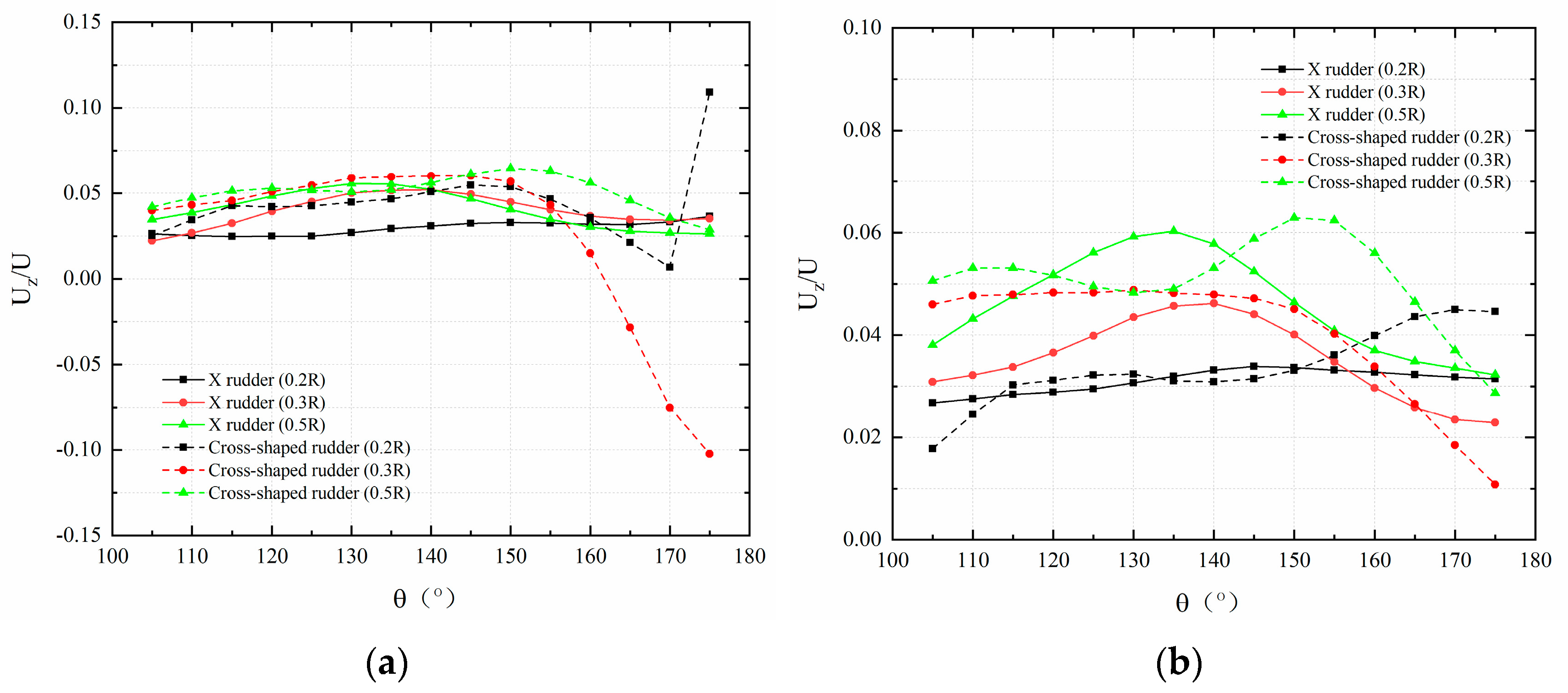
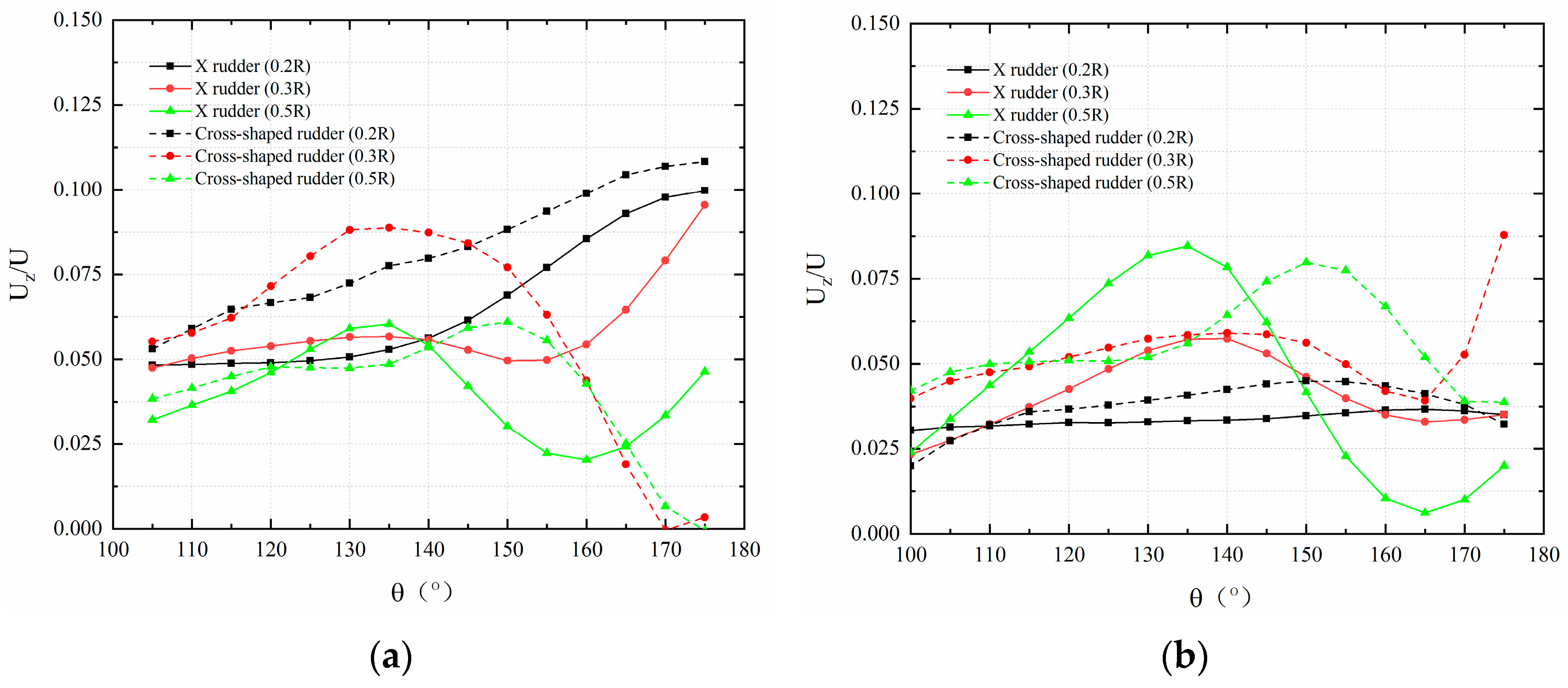
3.3. Stern Flow Field Distribution

In order to study the effect of the X-rudder on the submarine’s wake field, the velocities in three directions were extracted at the submarine’s propeller plane, which is located 0.048 L downstream of the trailing edge of the X- or cross rudder, respectively. Here, L represents the length of the submarine. The angle definition figure is shown in Figure 14:
The vertical downward direction of the submarine represents 0 degrees, and the vertical upward direction of the submarine represents 180 degrees. The origin is in the position of the central axis of the propeller plane. There are 72 measuring points on each full circumference. Due to the symmetry of the flow field and the comparison of the two kinds of SCS under this index, the inhomogeneity coefficients in this paper use a quarter-circle circumference.
The results for the nondimensionalized axial velocity are presented in Figure 15, Figure 16, Figure 17 and Figure 18.
The results for the nondimensionalized lateral velocity are presented in Figure 19, Figure 20, Figure 21 and Figure 22.
The results for the nondimensionalized vertical velocity are presented in Figure 23, Figure 24, Figure 25 and Figure 26.
In Figure 15, Figure 16, Figure 17, Figure 18, Figure 19, Figure 20, Figure 21, Figure 22, Figure 23, Figure 24, Figure 25 and Figure 26, U is the incoming velocity, i.e., Vlow or Vhigh, respectively. The axial velocity, lateral velocity, and vertical velocity of each spatial position in the flow field are U x , U y , and U z , respectively, and the dimensionless axial velocity, lateral velocity, and vertical velocity are defined as U x / U , U y / U , and U z / U , respectively.
Since the axial velocity has the strongest effect on the wake field, it was selected for further analysis. To quantify the inhomogeneity of the axial velocity distribution at the propeller plane, the root mean square (RMS) was used as a coefficient of inhomogeneity to characterize different regions/sections of the flow field. The RMS can reflect the variation of the sample, and it is expressed as V r m s = i = 1 N ( U i U ¯ ) 2 N . Here, U i is the dimensionless velocity at a specific sample point i, N is the number of sample points equally distributed over the circumference of an evaluation circle of radius r, and U ¯ represents the average velocity evaluated from all sample points of the evaluation circle. The magnitude of V r m s reflects the spread of variation of the velocity; the larger its value, the larger the variation of the velocity over the circumference of the evaluation circle of a certain radius. The distribution of the variation coefficients of the cross rudder and the X-rudder at different radii for different rudder angles is given in Table 5, Table 6, Table 7 and Table 8 and Figure 26, Figure 27, Figure 28 and Figure 29. R in Table 5, Table 6, Table 7 and Table 8 and Figure 27, Figure 28, Figure 29 and Figure 30 represents the diameter of the propeller; r in Table 5, Table 6, Table 7 and Table 8 and Figure 27, Figure 28, Figure 29 and Figure 30 represents the position of the circumferential radius of the measurement point.
In Table 5, Table 6, Table 7 and Table 8, it can be seen that (1) the velocity inhomogeneity coefficient of the X-rudder SCS submarine propeller plane exhibited a trend of decreasing first and then increasing with increasing rudder angle; (2) in the small radius region of the propeller plane (i.e., r/R = 0.2), the inhomogeneity coefficient of the X-rudder was generally smaller than that of the cross rudder. Moreover, the inhomogeneity of the flow field in the small radius region of the X-rudder propeller plane was significantly better than that of the cross rudder when operating at rudder angles of 2° and 5°. This difference may be caused by the difference between the all-moving and fixed stabilizers.
According to reference [24], a submarine with the 45° X-rudder has better hydrodynamic performance. The X-rudder designed in this paper was based on this conclusion. In terms of resistance testing, the conclusions in this paper were consistent with those in reference [8]. In terms of the measurement of lateral steering force and yaw moment, the conclusions of this paper were consistent with those in reference [6], and it was quantitatively proposed that “when the rudder angle was 10°, the lateral steering force and yaw moment of the X-rudder are about 2 times larger than that of the cross rudder”. The velocity contours of the flow field in reference [23] showed the degree of non-uniformity of the flow field of the two SCSs. In this paper, the parameter of non-uniformity of the flow field was proposed and calculated, the magnitude of the two was quantitatively compared, and provided the prerequisites for the conclusions in reference [23].

4. Conclusions

Tests were conducted in a ship model towing tank, and the submarine resistance, the lateral steering force, and the yaw moment were measured for different rudder angles of the cross rudder and the X-rudder, respectively. Furthermore, the velocity at the propeller plane of the two SCS submarines was also measured, and the following conclusions can be drawn:
(1)
Under the same rudder angle, the resistance of the X-rudder submarine was smaller than that of the cross rudder one at low speed, while at high speed, the resistance of the cross-rudder submarine was smaller than that of the X-rudder submarine.
(2)
Whether under low or high speed, the lateral steering force and yaw moment of the X-rudder were larger than those of the cross rudder under the same rudder angle. With increasing rudder angle, the improvement in maneuverability provided by the X-rudder became more apparent. At a rudder angle of 10°, the lateral steering force and yaw moment of the X-rudder were larger than those of the cross rudder, and the yaw moment of the X-rudder was about two times larger than that of the cross rudder.
(3)
With increasing rudder angle, the velocity inhomogeneity coefficient at the submarine propeller plane of the X-rudder SCS exhibited a trend of first decreasing and then increasing. In the small-radius region of the propeller plane (i.e., r/R = 0.2), the inhomogeneity coefficient of the X-rudder was generally smaller than that of the cross rudder. Finally, the inhomogeneity of the flow field in the small-radius region of the X-rudder propeller plane was significantly better than that of the cross rudder when operating at rudder angles of 2° and 5°.
The above differences, on the one hand, may be due to the different arrangement of the two rudders, that is, the X-rudders are the full-motion rudder, and the cross rudders are the flap rudder. On the other hand, this may be related to the different projection angles between the two types of SCSs and the enclosures and hydrofoils in front of the submarine.
As there will be quite a non-uniform wake in the upper part of the submarine, this makes it even more important to have a “base line” for the non-uniform flow, without the SCSs. With this “base line”, the influence of the SCSs on the uniformity of the flow becomes clearer. This can be considered in new or repeated experiments on this subject in the future work.

Author Contributions

Methodology—L.K. Investigation—Q.L. Data curation, J.Y. All authors have read and agreed to the published version of the manuscript.

Funding

This research was funded by The Science Foundation of China (Project 20140315).

Data Availability Statement

The data is unavailable due to privacy.

Conflicts of Interest

The authors declare no conflict of interest.

References

  1. Wang, Y.; Lu, K.M.; Yu, G.P.; Zhang, Z. Current status and development direction of foreign submarine acoustic stealth technology. Ship Electron. Eng. 2010, 30, 1–4. [Google Scholar] [CrossRef]
  2. Hu, J.; Zhang, W.; Guo, H. Numerical simulation of propeller wake vortex–rudder interaction in oblique flows. Ships Offshore Struct. 2021, 16, 144–155. [Google Scholar] [CrossRef]
  3. Rao, Z.; Yang, C. Numerical prediction of effective wake field for a submarine based on a hybrid approach and an RBF interpolation. J. Hydrodyn. 2017, 29, 691–701. [Google Scholar] [CrossRef]
  4. Yoo, W.J.; Yoo, B.Y.; Rhee, K.P. An experimental study on the maneuvering characteristics of a twin propeller/twin rudder ship during berthing and unberthing. Ships Offshore Struct. 2006, 1, 191–198. [Google Scholar] [CrossRef]
  5. Cao, Z.J. Research on Hydrodynamic Performance of Submarine X Rudder; Naval University of Engineering: Wuhan, China, 2019. [Google Scholar]
  6. Wang, S.Y. A small discussion on submarine X rudder. Ship Mater. Mark. 1999, 2, 36–37. [Google Scholar]
  7. O’Rourke, R. Navy Columbia (SSBN-826) Class Ballistic Missile Submarine Program: Background and Issues for Congress; Congressional Research Service: Washington, DC, USA, 2019. [Google Scholar]
  8. Mackay, M. Wind Tunnel Experiments with a Submarine Afterbody Model; Technical Memorandum DRDC Atlantic TM 2002-194; Defence R&D Canada-Atlantic: Dartmouth, NS, Canada, 2003. [Google Scholar]
  9. Broglia, R.; Dubbioso, G.; Zaghi, S. Analysis of a Submarine Manoeuvrability by Numerical PMM Tests. In Proceedings of the European Conference on Undersea Defence Technology (UDT2014), Liverpool, UK, 10–12 June 2014. [Google Scholar]
  10. Broglia, R.; Dubbioso, G.; Durante, D. Simulation of turning circle by CFD: Analysis of different propeller models and their effect on manoeuvring prediction. Appl. Ocean. Res. 2013, 39, 1–10. [Google Scholar] [CrossRef]
  11. Zaghi, S.; Dubbioso, G.; Broglia, R. Virtual PMM and Free Running Maneuvering Predictions of a Submarine by CFD. In Proceedings of the NAV 2015 18th International Conference on Ships and Shipping Research, Lecco, Italy, 24–26 June 2015. [Google Scholar]
  12. Zaghi, S.; Dubbioso, G.; Broglia, R. CFD analysis of turning abilities of a submarine model. Ocean. Eng. 2017, 129, 459–479. [Google Scholar]
  13. Suastika, K.; Virliani, P.; Wasis, D.A. Submarine rudder stern-plane configuration for optimum manoeuvring. EDP Sci. 2018, 177, 01024. [Google Scholar] [CrossRef]
  14. Feng, D.S. Overview of the Development of X-Rudder for Submarines and a Brief Description of the Research Application of X-Rudder in Sweden; National Defense Industry Press: Beijing, China, 1991. [Google Scholar]
  15. Shi, S.D. Maneuverability of Submarines; Defense Industry Press: Beijing, China, 1995. [Google Scholar]
  16. Zhang, T.; Lin, J.X. Study on the equivalent rudder angle of X-shaped rudder and cross-shaped rudder of submarine. Ship Sea Eng. 2004. [Google Scholar] [CrossRef]
  17. Luan, H.C.; Lin, J.X. Study on the relationship between maneuvering and motion of X-rudder submarine. Ship Sea Eng. 2007, 100–103. [Google Scholar] [CrossRef]
  18. Zhao, J.H.; Wang, B.Q.; Hou, D.Y. Research on the design method of stabilized wing for large depth submersible. Ship Mech. 2008, 12, 89–99. [Google Scholar]
  19. Hu, K.; Zong, F.Y.; Pang, X.N. Research on the design of equivalent rudder angle conversion device for X-rudder submarines. Ship Sea Eng. 2003, 19–21. [Google Scholar]
  20. Hu, K.; Pang, X.N. Design and simulation analysis of an equivalent rudder angle conversion device for X-rudder submarines. Ship Sea Eng. 2005, 47–50. [Google Scholar]
  21. Hu, K.; Xu, Y.F.; Wang, S.Z. Overview of submarine X-rudder development and analysis of its maneuvering control characteristics. China Shipbuild. 2007, 48, 130–136. [Google Scholar]
  22. Hu, K.; Wang, S.Z. Research on the design of underwater navigation body X-type orthogonal rudder control parameters. Mar. Eng. 2008, 37, 127–131. [Google Scholar]
  23. Zhang, L.; Xiao, C.R.; Jiao, Y.C. Numerical comparison of the hydrodynamic performance of cross-rudder and X-rudder submarines. Nav. Sci. Technol. 2017. [Google Scholar] [CrossRef]
  24. Jiao, Y.C.; Xiao, C.R. Layout optimization of submarine X rudder. J. Arms Equip. Eng. 2018. [Google Scholar] [CrossRef]
  25. Chen, J.J.; Pan, Z.Y.; Peng, C. Comparison of hydrodynamic characteristics of cross-shaped and X-shaped stern rudder navigating bodies. Chin. Nav. Res. 2020, 15, 10–18. [Google Scholar]
  26. Zhang, Y.; Li, Y.; Sun, Y. Design and simulation of X-rudder AUV’s motion control. Ocean. Eng. 2017, 137, 204–214. [Google Scholar] [CrossRef]
  27. Jeon, M.; Yoon, H.K.; Park, J. Analysis of maneuverability of X-rudder submarine considering environmental disturbance and jamming situations. Appl. Ocean. Res. 2022, 121, 103079. [Google Scholar] [CrossRef]
  28. Xia, Y.; Xu, K.; Huang, Z. Adaptive energy-efficient tracking control of a X rudder AUV with actuator dynamics and rolling restriction. Appl. Ocean. Res. 2022, 118, 102994. [Google Scholar] [CrossRef]
  29. Wang, W.; Xia, Y.; Chen, Y. Motion control methods for X-rudder underwater vehicles: Model based sliding Mode and non-model based iterative sliding mode. Ocean. Eng. 2020, 216, 108054. [Google Scholar] [CrossRef]
  30. Felli, M.; Falchi, M. Propeller tip and hub vortex dynamics in the interaction with a rudder. Exp. Fluids 2011, 51, 1385–1402. [Google Scholar] [CrossRef]
  31. Cozijn, J.L.; Hallmann, R. Thruster-Interaction Effects on a DP Shuttle Tanker-Wake Flow Measurements of the Main Propeller and Bow Tunnel Thrusters. In Proceedings of the International Conference on Offshore Mechanics and Arctic Engineering. American Society of Mechanical Engineers 2014, San Francisco, CA, USA, 8–13 June 2014; Volume 45387, p. V01BT01A011. [Google Scholar]
Figure 1. Cross rudder.
Jmse 11 02091 g001
Figure 2. X-rudder.
Figure 2. X-rudder.
Jmse 11 02091 g002
Figure 3. Cross rudder schematic.
Jmse 11 02091 g003
Figure 4. X-rudder schematic.
Jmse 11 02091 g004
Figure 5. SCS rudder movement to make the submarine turn right. (a) Cross rudder. (b) X-rudder.
Jmse 11 02091 g005
Figure 6. Coordinate system definition.
Jmse 11 02091 g006
Figure 7. Towing tank.
Jmse 11 02091 g007
Figure 8. Trailer work frame.
Jmse 11 02091 g008
Figure 9. Underwater PIV equipment accompanying the vehicle.
Jmse 11 02091 g009
Figure 10. PIV system testing process.
Jmse 11 02091 g010
Figure 11. Strain gauge balance.
Jmse 11 02091 g011
Figure 12. Six-component force sensor.
Jmse 11 02091 g012
Figure 13. PIV system underwater mine-body arrangement scheme.
Jmse 11 02091 g013
Figure 14. Circumferential angle schematic.
Jmse 11 02091 g014
Figure 15. The dimensionless axial velocity distribution at a rudder angle of 0°. (a) Low-speed (Vlow) condition. (b) High-speed (Vhigh) condition.
Jmse 11 02091 g015
Figure 16. The dimensionless axial velocity distribution at a rudder angle of 2°. (a) Low-speed (Vlow) condition. (b) High-speed (Vhigh) condition.
Jmse 11 02091 g016
Figure 17. The dimensionless axial velocity distribution at a rudder angle of 5°. (a) Low-speed (Vlow) condition. (b) High-speed (Vhigh) condition.
Jmse 11 02091 g017
Figure 18. The dimensionless axial velocity distribution at a rudder angle of 10°. (a) Low-speed (Vlow) condition. (b) High-speed (Vhigh) condition.
Jmse 11 02091 g018
Figure 19. The dimensionless lateral velocity distribution at a rudder angle of 0°. (a) Low-speed (Vlow) condition. (b) High-speed (Vhigh) condition.
Jmse 11 02091 g019
Figure 20. The dimensionless lateral velocity distribution at a rudder angle of 2°. (a) Low-speed (Vlow) condition. (b) High-speed (Vhigh) condition.
Jmse 11 02091 g020
Figure 21. The dimensionless lateral velocity distribution at a rudder angle of 5°. (a) Low-speed (Vlow) condition. (b) High-speed (Vhigh) condition.
Jmse 11 02091 g021
Figure 22. The dimensionless lateral velocity distribution at a rudder angle of 10°. (a) Low-speed (Vlow) condition. (b) High-speed (Vhigh) condition.
Jmse 11 02091 g022
Figure 23. The dimensionless vertical velocity distribution at a rudder angle of 0°. (a) Low-speed (Vlow) condition. (b) High-speed (Vhigh) condition.
Jmse 11 02091 g023
Figure 24. The dimensionless vertical velocity distribution at a rudder angle of 2°. (a) Low-speed (Vlow) condition. (b) High-speed (Vhigh) condition.
Jmse 11 02091 g024
Figure 25. The dimensionless vertical velocity distribution at a rudder angle of 5°. (a) Low-speed (Vlow) condition. (b) High-speed (Vhigh) condition.
Jmse 11 02091 g025
Figure 26. The dimensionless vertical velocity distribution at a rudder angle of 10°. (a) Low-speed (Vlow) condition. (b) High-speed (Vhigh) condition.
Jmse 11 02091 g026
Figure 27. The inhomogeneity coefficients of the cross rudder and X-rudder at a rudder angle of 0°.
Jmse 11 02091 g027
Figure 28. The inhomogeneity coefficients of the cross rudder and X-rudder at a rudder angle of 2°.
Jmse 11 02091 g028
Figure 29. The inhomogeneity coefficients of the cross rudder and X-rudder at a rudder angle of 5°.
Jmse 11 02091 g029
Figure 30. The inhomogeneity coefficients of the cross rudder and X-rudder at a rudder angle of 10°.
Jmse 11 02091 g030
Table 1. The dimensional details of the SCSs.
ParametersValue
Height of the SCSs0.065 L
The average span of the SCSs0.071 L
The average span of the cross rudder stabilizer0.037 L
The average span of the cross rudder flap0.034 L
The diameter at the longitudinal location of the SCSs0.059 L
The diameter of the submarine at the propeller hub0.048 L
The distance of the X-rudder from the bow to its axis of rotation0.91 L
Table 2. Resistance of two types of SCS submarines at low and high speeds.
SpeedReynolds NumberRudder AngleResistance (Non-Dimensional)
Cross Rudder
(Rcross)
X-Rudder
(Rx)
Relative Increment
(Rx − Rcross)/Rcross
Vlow1.34 × 106108.69%91.4%−15.90%
116.72%96.0%−17.76%
134.61%107.45%−20.18%
10° 146.1%111.62%−23.6%
Vhigh3.6 × 10691.9%97.9%6.53%
87.5%93.84%7.24%
91.05%100.31%10.17%
10° 91.3%100.87%10.49%
Table 3. Lateral steering forces for the two types of SCS submarines at low and high speeds.
SpeedReynolds NumberRudder AngleLateral Steering Forces (Non-Dimensional)
Cross Rudder
(Fcross)
X-Rudder
(Fx)
Relative Increment
(Fx − Fcross)/Fcross
Vlow1.34 × 106000
100%197.98%97.98%
131.97%354.56%168.66%
10°179.85%601.72%234.58%
Vhigh3.6 × 106000
93.97%147.55%57.03%
126.18%207.07%64.10%
10°206.55%593.3%187.25%
Table 4. Yaw moment for the two types of SCSs submarines at low and high speeds.
SpeedRudder AngleYaw Moment
Cross Rudder
(Mcross)
X-Rudder
(Mx)
Relative Increment
(Mx − Mcross)/Mcross
Vlow000
100%202.74%102.74%
132%363.08%175.06%
10°179.87%616.19%242.57%
Vhigh000
654.29%1051.91%60.77%
878.61%1476.28%68.02%
10°1438.16%4229.75%194.11%
Table 5. Comparison of the inhomogeneity coefficients of the cross rudder and X-rudder at a rudder angle of 0°.
Rudder AngleSpeedr/R Cross   Rudder   ( V r m s 1 )   X - Rudder   ( V r m s 2 ) ( V r m s 2 V r m s 1 ) / V r m s 1
Vlow0.20.0440860.137829212.64%
0.30.033870.121575258.94%
0.50.024470.067234174.77%
Vhigh0.20.0492270.07247847.23%
0.30.0668380.035276−47.22%
0.50.0263420.080717206.42%
Table 6. Comparison of the inhomogeneity coefficients of the cross rudder and X-rudder at a rudder angle of 2°.
Rudder AngleSpeedr/R Cross   Rudder   ( V r m s 1 )   X - Rudder   ( V r m s 2 ) ( V r m s 2 V r m s 1 ) / V r m s 1
Vlow0.20.1006870.039124−61.14%
0.30.1018150.066569−34.62%
0.50.0215180.05532157.09%
Vhigh0.20.0529860.029434−44.45%
0.30.0678650.072637.02%
0.50.0432170.0730669.06%
Table 7. Comparison of the inhomogeneity coefficients of the cross rudder and X-rudder at a rudder angle of 5°.
Rudder AngleSpeedr/R Cross   Rudder   ( V r m s 1 ) X - Rudder   ( V r m s 2 ) ( V r m s 2 V r m s 1 ) / V r m s 1
Vlow0.20.0453560.015313−66.24%
0.30.0831410.0885126.46%
0.50.0300790.094571214.41%
Vhigh0.20.0522240.022227−57.44%
0.30.0705550.038828−44.97%
0.50.0396220.05955550.31%
Table 8. Comparison of the inhomogeneity coefficients of the cross rudder and X-rudder at a rudder angle of 10°.
Rudder AngleSpeedr/R Cross   Rudder   ( V r m s 1 )   X - Rudder   ( V r m s 2 ) ( V r m s 2 V r m s 1 ) / V r m s 1
10°Vlow0.20.1139190.042532−62.66%
0.30.0506260.08009758.21%
0.50.0388470.096596148.66%
Vhigh0.20.0845260.018341−78.30%
0.30.0855130.09700113.43%
0.50.0636630.174736174.47%
Disclaimer/Publisher’s Note: The statements, opinions and data contained in all publications are solely those of the individual author(s) and contributor(s) and not of MDPI and/or the editor(s). MDPI and/or the editor(s) disclaim responsibility for any injury to people or property resulting from any ideas, methods, instructions or products referred to in the content.

