1. Introduction
The shipbuilding industry has seen changes as a result of efforts to cut costs and delivery times while preserving and even enhancing quality. These changes have affected all processes, including the design, construction, and project management processes. Among these, the design process has been the one most impacted by the other processes, despite the fact that all of them are connected and share the goal of making the ship better, quicker, and cheaper. For instance, the requirements for building optimization has led to the development of the concept for a building strategy and the requirement to deliver intermediate product designs. Additionally, the simplicity of reducing costs by outsourcing duties prompted shipbuilders and designers to take up remote engineering and collaborative design.
The design process has traditionally consisted of a series of phases, including concept (preliminary) design, basic (class) design, and detail design, each having its own goals and range of supplies and conducted in a sequential manner but portrayed in a spiral fashion [
1].
These steps are conducted in order, each beginning after the conclusion and approval of the preceding one (
Figure 1).
Nevertheless, the aforementioned developments have made it necessary to forgo the sequential execution of these phases, thus overlapping them and necessitating the beginning of one before the preceding one has been completed or authorised. Furthermore, three steps are frequently conducted concurrently. Therefore, the traditional chart has been transformed from a spiral into a series of concentric rings where it is unclear when one stage ends and the next one begins. This design approach, which we might refer to as the “integrated design process,” has become the norm for ship design (
Figure 2).
Although the different design stages do not necessarily occur in a clear chronological order, as each one has a distinct effect on the project’s final cost, the design and the construction and operating lifetime of the unit need to be considered. In this sense, the effects of choices made early in the process are considerably more significant than those made afterwards. This feature suggests using the similar design tools for all design phases, along with the risk of only being able to assess the success of the decision after the completion of the design stage.
A large percentage of ship designs are based on 2D tools for their conceptual and basic design. Using a 3D approach at this stage is usually only used in long-term naval projects, given that errors at this stage can be very costly.
Although there are clear advantages to using a 3D design approach early in the design, the promotion of the solution remains a challenge.
Based on a shipbuilding-oriented CAD tool, the benefits of this approach will be presented, and the reader will be provided with an overview of the entire design process covering the conceptual, basic, and detailed design.
2. Early 3D Design Challenges
In shipbuilding, the debate over the benefits of early 3D models started decades ago [
2,
3]. It began as a philosophical exercise instead of a viable alternative, partly due to the tools available not being adequate to guarantee its success at the start of the design process. As a result, most ship designers are still using 2D tools at this stage.
Nowadays, the methodology remains the same. However 3D CAD/CAM/CAE has experienced a considerable transformation. Adding significant and innovative new capabilities is the only way to generate a 3D model easily [
4].
Even when all stakeholders continue to debate the advantages and disadvantages of either methodology, there is a general phasing out of paper use in the workplace. This is evident in multiple industries and disciplines, which encourage and support the efforts done with the introduction of digital tools.
With these concepts discussed, our experience has proven that conceptual and basic design stages are exceptionally time-consuming. Given the options and time, a design team should engage in building a 3D model even if the tools provided are not overly practical. However, time limitations added to the demand for a large amount of information and the quality required may be seen as unfeasible. Nevertheless, this is the area that will be addressed by the 3D approach, as it will ensure the quality of the design and information as well as prevent the errors and inconsistencies characteristic of the more traditional methodology.
To address the time concerns, any solution will require a series of capabilities that is aimed at providing a simple and automated process. Therefore, it is essential that these include the reduction of the number of clicks, modules, and commands. If implemented correctly, it will offer the prospect of generating early 3D models that are accurate and will be sufficiently rapid to be competitive with the 2D methodology. Given the global philosophy inherent to this approach, the reutilisation of information will provide a smooth transition to the detailed design stage. Additionally, there are other advantages to the proposed methodology, such as weight and the accurate positioning of the main equipment, which will be critical during all design phases. It should be noted that some authors argue that speeding up a synthesis approach may not provide an overall time saving due to the complexity of some ships [
5]. Therefore, this approach does allow for a more comprehensive methodology that will satisfy spatially driven designers.
3. The 3D Philosophy
In order to have the 3D CAD approach feasible, there are significant aspects that need to be considered, and are discussed below:
Database: Typically, a 3D CAD is created on the basis of an electronic database that ensures one true copy of information throughout the entire design method.
Topology: The chance of introducing swift modifications which will be spread across the model is possible due to the topology-centred CAD tools. This feature can have a significant impact especially when a large amount of genuine information is present.
Integration: All disciplines in CAD ought to be completely integrated into a common framework. Therefore, the first 3D model is assembled using a similar tool to the one used for the detailed stage. This permits the reutilisation of data, and in turn, significantly reduces the design effort.
The proposed solution is predicated on a model where the geometry and, therefore, the attributes of the components of the product are kept. The 3D ship product is developed as a critical component of the engineering work, and it may be used as a visual aid and exploited to retrieve data for material procurement and production. In the following sections, the main attributes applicable to the ship product model are discussed.
Developing an early 3D model using CAD tools enables an improvement of the design process method of the ship and a swifter review of multiple design alternatives, which in turn reduces the delivery time and associated costs [
6]. The benefits derived from the proposed solution can be attributed to the design time reduction—and therefore costs—and the improvement of the design. The financial advantage is evident given that the early design stage constitutes the majority of the costs and that optimisation also provides a quality in the design, building, and operation of the ship. During this project, an undisclosed number of ships’ designs were analysed, and as an average, it was determined that the reduction in person-hours reached 15%.
As the sustainability goals of the shipbuilding industry are pushing for energy and material efficiency as well as overall environmental practices that cover the whole ship lifecycle, improvements in those areas are becoming a priority. The technical advancements that are being developed in the context of maritime industry 4.0 (Digital Twin, IoT, Virtual, Augmented and Mixed Reality, Artificial Intelligence, Big Data, Data mining, Data Analytics, Machine Learning, and Simulation) allow for an improved connection between the real asset and the design. Recent studies suggest that the use of a 3D model in the form of a digital twin allows for a 20% productivity increase, owing to the early outfitting definition and a reduction of energy consumption and registered injuries [
7]. Additionally, the early definition of the materials required allows for an alignment with the material requirements planning and just-in-time (JIT) practices. Every stage of the shipbuilding process has a resource consumption and a waste component attached that will benefit from an early definition granted by the 3D approach, as it will allow for a better implementation of strategies that focus on coordination and control of the operation procedures. Additionally, it can support the evaluation and monitoring activities that will not only serve material optimisation but control waste and pollution during construction.
Therefore, achieving improved performance while developing the design and, simultaneously, developing a product of prime quality in an exceedingly competitive manner is a conceivable proposition. The ideal CAD solution is built around the integration of all the design stages and disciplines given the use of a single database. Therefore, it will allow for the adoption of collaborative engineering and will ensure data integrity. The authors have noticed an increase in the interest in collaboration from different parties including vendors, shipbuilders, designers, and classification societies. This has manifested in the latest 20th International Conference on Computer Applications in Shipbuilding (ICCAS 2022) organised by the Royal Institution of Naval Architects and the 21st International Conference on Computer and IT Applications in the Maritime Industries (COMPIT’22). However, outside the respective organisations, there are obvious challenges, including intellectual property, uncertainties, and perceived value [
8] that in most cases are relegated to informal meetings. Moreover, some solutions include encouraging data exchange formats for model-based class approval such as the OCX [
9,
10].
Given the availability of advanced functions in numerous CAD systems, the definition of the model is simplified. Using a topological model in favour of a geometric model simplifies its definition, enables rapid exploration of multiple design alternatives, and simplifies very common changes in the early design stages. A major advantage of online topology definition without storing geometry data is that by simply reprocessing, the modifications to the main hull surfaces are automatically reflected. Additionally, topology definitions reduce the need of the less efficient manipulation of the geometry given the use of powerful copy command options. An additional advantage of topological models derives from the size of the information, with these models being less storage intensive compared to the geometric models, reducing the volume of the database. [
11]. Due to the amount of detail required, some authors have championed virtual reality for use in early-stage design [
12]. Although the implementation of the system remains a challenge, the overcoming of this challenge can bring important productivity and quality gains to the shipbuilding process [
13].
The definition of a single-delivery 3D version, available to multiple designers operating concurrently, has become a key component for use in all levels of the layout. Through use of an innovative top-down definition, the extent of the element increases, and the particular components of the model are partitioned. With operations such as block splitting, the direct transition from basic to detailed design is simplified and enables the attributes and part assignment to blocks to be used during the manufacturing stage where the configuration of the model is employed.
4. Basic Design Process
The definition of forms files, hydrostatic calculations, volume definitions, analysis of the intact and damaged stability conditions, and the supplementary concepts of naval architecture are the first steps in the fundamental design process in CAD. With the plates and profiles later specified in the material catalogues. To create the principal holes in all surfaces, the hull structure module is utilised and includes the scantling of the main surfaces for plates and profiles. Additionally, other key structural elements are defined after the hull forms, decks, bulkheads, and other surfaces have been created (floors, web frames, girders, stringers, etc.).
The definition is typically based on the frame and longitudinal systems, which allows for a complete recalculation of the model if required due to a change in the spacing between elements. This will be possible given the typical definition of the frame and longitudinal systems.
The plates and profiles are instituted as entities depicting surface areas that share scantling properties. As a result, the dimensions of these objects are inconsistent with manufacturing practices and are considered in the later stages of the design process. Other properties can be defined at any time, with some examples being the continuity and water tightness of partial or full surfaces.
In CAD, there is a great deal of freedom when considering the definition of the model, making it feasible to construct, at any stage, the plates and profiles. However, designers typically adhere to the same guidelines as with 2D design, commencing with the specification of the continuous elements in order to enable the automatic splitting of noncontinuous elements.
The categorisation requires a level of detail shown in
Figure 3 and includes the part types (brackets, clips, face bars, collars, etc.) and other relevant features. At this point, the assembly breakdown to a unit or block is optional (profile end cuts, scallops, notches, etc.).
4.1. Surfaces and NA Calculations
The external hull form, superstructures, bulkheads, decks, and appendages are all included in the ship moulded surfaces model. The collection of Bezier patches, trimmed NURBS patches, ruled surfaces, and implicit surfaces (planes, cylinders, spheres, and cones) constitutes the surface geometrical representation of the specific software. The surfaces imported can be stored in a variety of standard formats, including AP-216 STEP and IGES.
For surface definition, there are CAD tools that include two complementary tools. The use of conventional tools enables the specification of hull surfaces in either regular or unique configurations, such as asymmetrical, multihull, and offshore platforms. With the help of this tool, it is possible to simply conduct operations like lengthening or shortening a ship as well as a wide range of hull form transformations (based on the longitudinal position of the centre of buoyancy, block coefficient, or quadratic). CAD programmes have recently added an additional tool based on the most modern mechanical design technology that can be used to improve hull forms.
When an adjustment is made to higher-level notions, the automatic recalculation of all elements (material standards or hull and decks surfaces) is achieved through the extensive use of topology. Given that during the creation of the fundamental design, changes are made regularly, this kind of topological description results in considerable time savings.
Analysing the hydrostatic and stability calculations is achievable once the surfaces have been determined. There are businesses that have created new modules collecting all the features of naval architecture for these objectives.
4.2. Volume Definition
The compartment arrangement of the project is defined in the following phase of the basic design definition and is based on how spaces are defined. A 3D model of each space serves as a representation.
New programmes or modules have been created by certain software companies for the definition of general layouts in 3D. These programmes or modules are devoted to planning and controlling a ship’s compartment layout. A 3D model of the rooms is created and used as a guide for the ship’s surfaces and auxiliary aircraft. Additionally, in a certain defining environment, it would be able to define spaces from 2D graphics. For hydrostatic and stability calculations, the compartment layout specified on these software tools would be available in other applications or CADs.
4.3. Hull Structure Basic Design
4.3.1. Shell and Decks Definition
Plates, profiles, and holes may be defined in this 3D curved surface environment. The surface and zone concepts are used to provide work division and enable multiuser access to any surface. It is possible to use a generic zone to house the entities shared by multiple zones. It is possible to define the following profiles:
The primary topological references to structural features that already exist along with auxiliary concepts employed in the early design stages serve as the foundation for profile definition (longitudinal spacing, frame system, other profiles, etc.). Therefore, it allows for a quick assignation of multiple attributes, including material, web, scantling, and thickness orientation required by the user. At any point during the design process, constructive qualities (such as parametric webs and flange end cuts) can be added to complete these fundamental characteristics. When moving from basic to complex design, the profiles might later be divided into profile components. The requisite cutouts and scallops would automatically be generated when profiles crossed other profiles.
Solids are used to represent all profile forms, including flat, curved, and twisted profiles. A degree of accuracy that can be selected by the user is used to display the web, flange, and associated end cuts.
As a result of the extensive use of topology, the early design stages can benefit from the early shell and deck plating definition. The fundamental ideas in this regard are the following [
14]:
Butts: These are surface-based lines that serve as the plates’ rear and forward limits. Butts can be found on transverse planes at any abscissa and can take any shape.
Seams: These are lines of any geometric shape that are laid out on a surface and used as bottom and upper bounds for plates. Typically, seams are defined using a set of surface-based points and extra rules to specify the layout.
Plates: These are areas of the surface that are defined by the lower and upper seams, aft and fore butts, and shrinkage factors, construction margins, and bevelling/edge preparation. Another way to create plates is to divide an already-existing plate into two smaller plates.
To facilitate the generation of an early material take-off list, features such as the automatic creation of the plate predevelopment and the solid representation (including thickness) of the curved and flat plates are incorporated.
4.3.2. Internal Structure
Built on the same high-performance visualisation and topological environment as the curved surfaces, the internal structural framework applies to a section that is laying on a plane. This framework allows for a simple definition and modification of plates (flat, flanged, and corrugated), holes, straight and curved stiffeners, standard plates, face bars, collars, on- and off-plane brackets, and other structural elements. Multiple portions in memory, which makes tasks like copying or editing items in various sections simple, are also a common feature. The ideas of section, structural element, and zone are used to create the work division and allow different users to access any area.
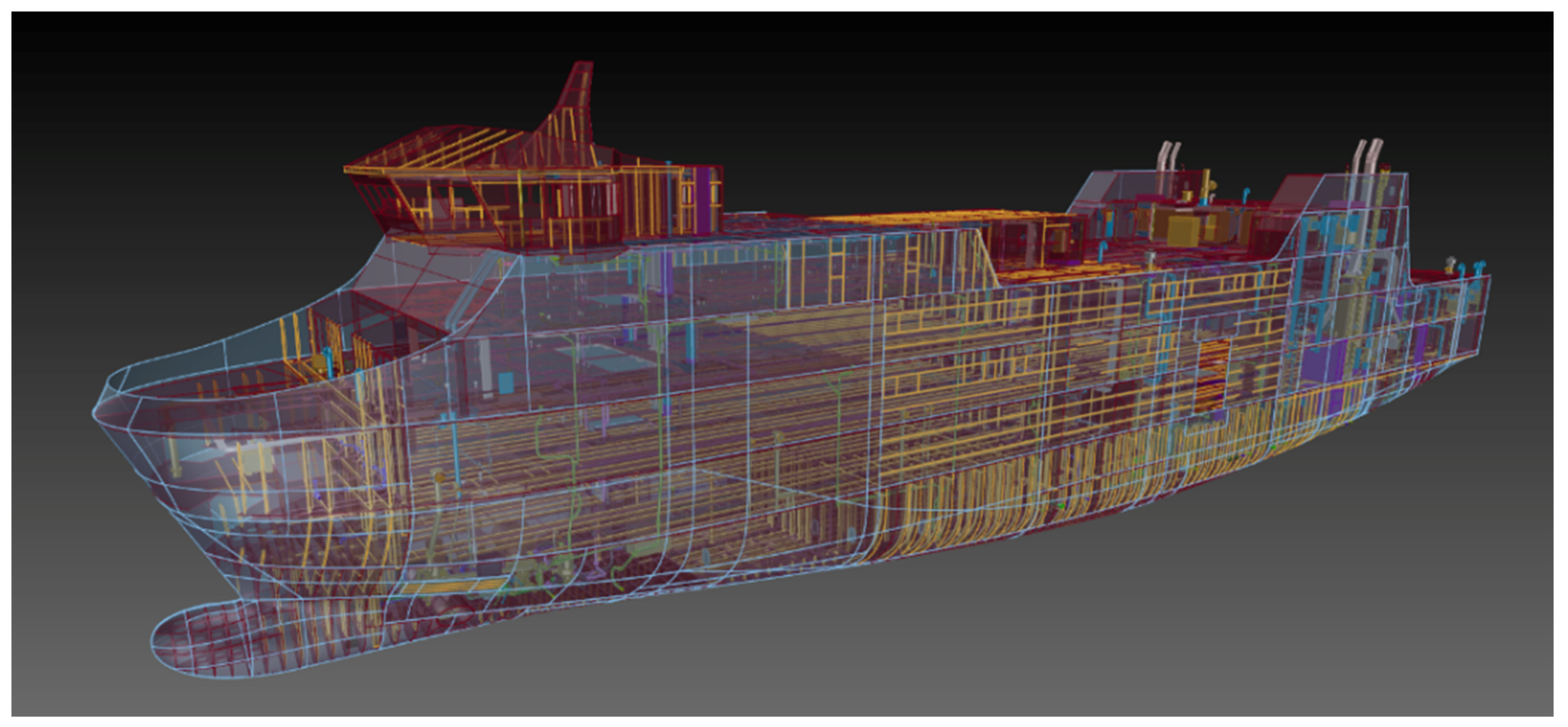
Figure 4 shows, as an illustration, a simple-design ferry produced using a CAD system’s structure module.
The main features are as follows:
Best practices are supported by the establishment of default constructive values and parameters for profiles, plates, and face bars, given the usage of the structural element concept;
Automatic portion separation based on the structural element attribute of crossing or not crossing;
High productivity tools, including split and join functions for profiles and plates, one-click plate definition, and minimization of auxiliary geometry;
The definition of plates, face bars, and profiles using a high-performance topological definition language based on XML;
Definition and automatic application of standard or free-form holes to the impacted plates;
Profile and face bars definition using parametric web and flange end cuts, parametric cutouts, and standard profile cross-sections;
Insertion of cutouts automatically for plates and profiles.The inclusion of high productivity commands (split, multicopy, and multiedit) for both plates and profiles in distinct or the same sections’ structural parts.
4.4. Main Equipment Positioning
Following the definition of the structure over the hull forms, the disciplines of outfitting and electrical work are required. The most important step is to arrange all of the components of the primary equipment, such as the main engines, reduction gear, and propeller shaft, as indicated in
Figure 5.
Other equipment components with large volumes and/or surfaces are also a part of the fundamental design. Initial stability estimates may be used to position outfitting equipment like large water ballast systems or electrical equipment such as transformers and auto generators.
4.5. 3D Model Output Generation
The next sections outline the definite results of the 3D model of the hull structure early deployment, such as drawings, reports, and models for the analysis and computation tools. Given the availability of a 3D model increases the effectiveness of the tasks involved in the fundamental design, they become another significant advantage of this approach.
4.5.1. Class Approval Drawings
The strategy outlined in this article is more generic, but any enhancements to the basic design process must consider the fact that the classification drawings for approval are the primary output of the hull structure’s basic design stage. Currently, the potential of 3D models for class approval is being considered and includes efforts from shipbuilders, designers, and class societies. However, some authors believe that there are still challenges concerning integration and visualisation [
15]. Classification drawings are symbolic images and can include the following:
Typical planar sections;
Shell and deck drawings;
Other detail drawings.
Typically, a single module in a CAD system is in charge of overseeing the output drawings from all design disciplines (hull structure, general, outfitting accommodation and electrical). Since the final considerations of the drawings rely on the operator’s needs, the drawing creation is entirely user configurable. Additionally, there is a continuous update of the model on the most recent version, and the 2D entities are linked to the 3D components that represent the product model. Furthermore, the system converts the 3D product model into usable drawings. For modelled elements, a symbolic representation is conceivable, and there are manifold visualisation techniques accessible.
A feature from the drawing generation module allows for the reprocessing of the visual output following model changes while maintaining any manual adjustments made by the user.
Additionally, there are possibilities for automated dimensioning and labelling using user-customizable formats and templates that reflect various aspects of the chosen items (identification, end-cuts, profile cross-section scantling, and others). The components of the product model are also connected to these entities. The created drawings can also be used with the majority of common drawing formats.
4.5.2. Other Outputs
Given the entire product model is maintained on an absolute source of information, one of the benefits of 3D application integration is the ease of data extraction, and this is further facilitated by the fact that reports created using a CAD application can be customised and exported to the majority of common formats including Excel, HTML, and ASCII.
Depending on the user’s chosen query requirements, fixed contents reports such as adjustable bills of materials and steel orders (profiles and plates) can be received. The degree of project definition determines the contents of the report.
In a typical CAD system, the following reports, among others, may be obtained:
5. Finite Element Implementation
An essential stage of the basic engineering of any vessel concerns the structural analysis. To confirm the viability and improve the structural design of the ship, the aforementioned engineering analysis is performed using the finite elements method (FEM). Creating a proper model for computation, applying loads and constraints, processing, meshing, postprocessing, and analysing the outputs are all challenging tasks that must be completed in practice.
Despite the inclusion of 3D CAD models in standard formats for direct import in the majority of finite element programmes, given how complicated ship models have become, they cannot be used with models from the shipbuilding sector. The analysis process is significantly slowed down by using a calculation-oriented approach to effectively replicate the model instead of using the more labour-intensive manual simplification of the model.
The early phases of design performance can be optimised by using a ship model that has already been developed in a 3D CAD for FEM analysis. This requires an effective connection between the two programmes so that a ship model that is condensed and customised for each kind of computation may be exported straight from CAD.
A recent development which blends creative techniques to the CAD/CAM shipbuilding applications tackles this challenge to produce the desired outcomes: a link that enables the export of a simpler ship model by using its topological properties, as illustrated below (
Figure 6). To ensure the quality of the model transferred, functional algorithms in a generic CAD should enable the production of an intelligent model by streamlining, filtering, and removing extraneous data.
The user can select from a variety of features, including the following:
Whether the plates are translated by surfaces with the moulded line or the neutral axis;
The scantling automated colour assignment to each profile and material;
Whether the visual of curves or surfaces are used for the profiles;
The smallest region that can be discarded after transferring brackets and holes.
All structural entities can be exposed to an idealisation procedure that follows the criteria shown below and seeks the simplification of the 3D model:
Elimination of notches, scallops, fillets, and chamfers from the outside contour for plates;
Elimination of profile extensions, scallops, notches, end-cuts, and macro-holes from profiles (through surfaces or curves);
Topological extension of surfaces defined as plates or profiles to the moulded line/neutral axis of the surface that is applicable to the plate or profile definition of the surfaces intersecting lines;
Extension of plate limits to the defined surface boundaries;
Surface sewing on the joint line of surfaces that originate from a split and allocating planar faces to flanged and corrugated plates;
Web and flange sewing when a surface defines a profile, with an underlying plate surface sewing of the resulting web surface profile;
Separation of plates by means of marking lines in distinct surfaces.
Additionally, some research suggests that by using a single 3D product model, the initial planning process for structural optimisation could be streamlined and result in the standardisation and automation of time-consuming tasks, for example, by having the time to undertake the strength evaluation and weight estimation of the midship structure be significantly reduced [
16].
6. Detail Design Transition
An essential feature of any software system that aims to deliver a comprehensive solution for ship design and production is to enable an effortless transition that avoids rework between any design stage and, therefore, reduces the risk of delays. Consequently, CAD offers tools for dividing and joining plates and profiles as a logical extension of the basic design. In addition, attributes that are not relevant during the basic design stages, such as part definition, construction margins, bevelling, and shrinkage factor, can be included and will be required during detailed design.
The transition from the original, conceptual, and abstract design to the fundamental, comprehensive design is likewise the transition to the concrete and manufacturable design. In utilising all the data supplied during the conceptual stages, large conceptual pieces that are valuable for analysis, such as structural behaviour and weight, need to be transformed into manufacturable components by adding details as needed.
In this transition, the concept of splitting is fundamental, with cases such as manufacturable profile sections resulting from the splitting of large longitudinal layouts inheriting the design characteristics and having the appropriate splitting qualities based on end-cuts. From bulkhead shapes to curved hull plates, the split idea is used for every type of element.
The degree of detail (as seen in
Figure 7) includes both attributes and geometry. When designing in detail, part properties that were unnecessary in the conceptual stages become crucial. Tools to alter, inspect, and copy properties of sizable groups of components are offered in order to ensure a seamless transition.
Block subdivision between design steps of the ship configuration is probably one of the most significant considerations. Although split and refinement tools are available to complete an automated recalculation of portions when the block butts are updated, certain particular tools are also offered. By using a powerful graphical selection tool, components may be assigned to units at any moment (i.e.,
Figure 8).
Lastly, this is the stage where the detail design is completed. This is achieved by defining the sections that are not pertinent during the basic design phase.
7. Benefits in Area of Improvement
The advantages of the discussed strategy are as follows:
It offers a swifter evaluation of various design options and automated recalculation in the event of upper-level changes emanating from the high level of topology.
Creating a 3D model early in the design process enables us to make decisions based on facts rather than educated guesses, such as in early material and weight estimation, including painting and welding.
There is a reduced likelihood of discrepancies compared to the two-dimensional methodology, where each view is independent of the others and has no relationship to them. Instead, the 3D technique combines the user’s graphical verification with the implicit intelligence associated with the model through specific qualities (continuity, watertightness), resulting in a higher quality design.
An easier integration, achieved through a common 3D model with calculation and analysis tools to be handled in the FEM/FEA modules for further calculations, undergoes an idealisation process. The majority of these calculations are conducted in the initial stages of the basic design.
The most important elements of the ship, as well as the weights and centres of gravity, may be established quickly, owing to the most significant equipment’s positioning.
The model is developed incrementally as the design progresses, resulting in a smooth transition to detailed design based on data reuse that shortens design time and streamlines the procedure as a whole.
Due to the usage of a 3D tool, the design is more precise.
Easier cooperation across disciplines is possible since the hull structure and different outfitting disciplines are modelled using the same base product. This improves the outfitting design in terms of the overall arrangement definition and important compartment layout and has apparent benefits in terms of interference or collision inspections.
Early design phases of the 3D model enable virtual reality viewers to navigate around it. This is a significant benefit for marketing initiatives or for intuitively managing the design process.
The areas for development identified are the following:
The creation of the 3D model itself is clearer since more advantages would be realised there. There are significant opportunities for development, such as reducing and streamlining the model’s generation.
The solution must be adaptable and simple to use. Those involved in conceptual and basic design work mostly use 2D tools since they are so user-friendly, and having a really helpful tool is essential.
8. Conclusions
CAD systems increase the accuracy of designs, lower the likelihood of discrepancies, and improve overall design quality [
17,
18].
In addition to the effective integration with finite element analysis tools, further benefits include the quick examination of various design and the preliminary determination of weight, welds, painting and other coatings, and materials. Additionally, it makes it easier to define outfitting (overall layout and arrangement of crucial compartments) and enhances disciplinary coordination. In short, the easy transition to detailed design and information reuse are the main features.
The integration between product lifecycle management (PLM) tools and different CAD systems is another recent breakthrough. PLM can handle challenges such as traceability, which can be dependent on all processes: process management, configuration, and the control and release lifecycle. Moreover, there is continuous work being done towards reducing what is known as “island solutions” [
19,
20].
When the continuation of the detailed design is taken into consideration and/or the scope of work includes the outfitting design, it is anticipated that this significant innovation in the basic design development will become the standard practice in the coming years. When the continuation of the detailed design is taken into consideration and/or the outfitting design is included in the scope of work, it is anticipated that this significant change in the development of the basic design stage, which is now required and being implemented, will become the standard way of working in the coming years.
Additionally, the required computational power to manage the increasingly detailed models is enabling the efficient introduction of these solutions. State-of-the-art hardware progressively incorporates new processors that enable enhanced graphics. On the software side, operating systems are being developed especially adapted for such devices (such as Android or IOS), allowing interfacing with improved functionalities.
The vast majority of a ship’s costs are known to be spent during the initial design stages. The proposed solution provides tangible benefits because it optimises the process by reducing the time spent on design and, as a result, the cost [
21]. Furthermore, it will benefit the procurement logistics stage of the process and favour material optimization in accordance with sustainable policies, specifically the Sustainable Development Goals included in the 2030 Agenda for Sustainable Development.


