Article

Multi-Scale Analysis for Assessing the Impact of Material Composition and Weave on the Ultimate Strength of GFRP Stiffened Panels

1
Key Laboratory of High Performance Ship Technology (Wuhan University of Technology), Ministry of Education, Wuhan 430063, China
2
Green & Smart River-Sea-Going Ship, Cruise and Yacht Research Centre, Wuhan University of Technology, Wuhan 430063, China
3
School of Naval Architecture, Ocean and Energy Power Engineering, Wuhan University of Technology, Wuhan 430063, China
4
Centre for Marine Technology and Ocean Engineering (CENTEC), Instituto Superior Técnico, Universidade de Lisboa, 1049-001 Lisboa, Portugal
*
Author to whom correspondence should be addressed.
J. Mar. Sci. Eng. 2023, 11(1), 108; https://doi.org/10.3390/jmse11010108
Submission received: 5 December 2022 / Revised: 30 December 2022 / Accepted: 1 January 2023 / Published: 5 January 2023

Abstract

:
A micro-meso-macro analysis framework based on the multi-scale method was employed to analyse the mechanical behaviour of marine GFRP stiffened panels. The study aims to establish a procedure for assessing the impact of material composition and weave on the ultimate strength of GFRP stiffened panels. The ultimate strength assessment was an essential step in the design process, and the investigation of construction materials has a great benefit to the lightweight design of marine composite structures. The micro- and meso-scale RVE models of components used in GFRP materials are established, and their failure criteria and stiffness degradation models are created using the user-defined material subroutine VUMAT in ABAQUS. The equivalent material properties at the micro-scale (meso-scale) obtained by a homogenisation method are used to define the meso-scale (macro-scale) mechanical properties in the finite element analyses. The multi-scale method assesses the macro-mechanics of composites, and it is shown that the ultimate strength of GFRP stiffened panels is mainly determined by the failure of CSM fibre bundles and WR yarns. Parametric study of the meso-mechanics of composite materials can provide an analysis tool to obtain the optimal macro ultimate strength of the composite stiffened panel.

1. Introduction

Glass-fibre reinforced polymer (GFRP) stiffened panels have been widely used for various kinds of structures in marine engineering, especially for the hull of special service crafts [1,2]. The GFRP stiffened panel has been also used in the superstructure of high-speed ships and large passenger ships. The GFRP materials are often fabricated by the chopped strand mat (CSM) and woven roving (WR) laminates. The damage mechanics of composite materials are complicated, involving anisotropy, inhomogeneity, failure mode, etc. These characteristics affect the strength of composite structures, and their analyses provide the method for assessing the complex material design on the strength of composite stiffened structures of ships and offshore platforms.
The ultimate strength of the GFRP stiffened panel is the fundamental aspect in the structural assessment of ship hull girder strength, but the sensitivity of material parameters on the structural strength is unknown. The macro-scale material properties of composites are relevant to the micro- and meso-mechanics of their components. A multi-scale method can establish the relationship among the micro-, meso-, and macro-scale models for composite structures [3,4].
In the GFRP composite plates, CSM laminates are made of fibre-reinforced composites, and WR laminates are made of braided composites. These are the two main composite models to design composite laminates.
The fibre-reinforced composites combine two materials, and the reinforcing phase, i.e., fibres, is embedded in the matrix phase. Their failure behaviours at the micro-, meso- and macro-scale have been investigated by the multi-scale finite element analysis using representative volume element (RVE) models [5,6,7,8,9,10]. The reasonable progressive damage model has to be established to obtain accurate results in the multi-scale analysis [11,12,13,14,15].
Ivancevic and Smojver [16] compared the accuracy of various failure criteria for evaluating the ultimate strength of laminated composite structures. Li et al. [17] proposed a multi-scale failure criterion to determine the fibre and matrix failure modes at the microscopic level, establishing stress transfer, damage determination, and evolution methods. To generate random fibre distribution for unidirectional fibre-reinforced composites, Liu et al. [18] conveniently created the microstructures with different fibre volume fractions by distributing every fibre with inter-fibre distance arrangement.
The braided composites are produced by interweaving two or more fibre yarns with a certain braiding angle. To better simulate the mechanical behaviour of braided composites, a reasonable multi-scale model has to be developed [19,20,21]. The accuracy of the multi-scale model relies on the correct establishment of the meso-scale model. Zhang et al. [22] used an RVE model considering yarn contact and interference, combined with periodic boundary conditions, to simulate the progressive damage behaviour of a 3D woven composite. Shen and Gong [23] developed a meso-scale numerical modelling approach to analyse the material’s macroscopic properties based on the braiding process and force analysis of yarn.
Based on the mechanical analysis, the influence of material parameters such as braiding angle, fibre volume fraction and pore size on mechanical properties was studied [24,25,26,27]. In addition, Smilauer et al. [28] used concurrent multi-scale analysis to predict the fracture energy and adequate length of the fracture zone of two-dimensional three-way woven composites. Zhao et al. [29] established a multi-scale simulation framework for micro-, meso- and macro-scale unit cell models to analyse the impact failure behaviour of triaxial woven composites. The framework was used to determine the equivalent properties of fibre bundles, predict the equivalent properties of the unit cell, and simulate the impact failure behaviour of woven composites. Based on multi-scale analysis, the effect of pore defects on mechanical properties of 3D braided composites was studied [30,31,32,33].
Although the multi-scale method of composite materials has been widely applied to analyse the aerospace structures, it is rarely applied in marine engineering. The load and structural types are different between aerospace and marine structures. Establishing the procedure to analyse marine structures is essential since improving the strength of composite vessels relies on the composite material design method. The present work aims to establish the multi-scale analysis procedure for assessing the effect of material composition and weave on the ultimate strength of marine GFRP stiffened panels. It is focused on the numerical method for analysing the micro-meso-macro mechanics in marine composite structures and the way is open for testing future materials. The investigation is beneficial to the lightweight design of marine composite structures. The micro- and meso-scale RVE models of components used in GFRP materials are established. Their failure criteria and stiffness degradation models are created using the user-defined material subroutine VUMAT in ABAQUS. The homogenisation method is used to obtain the equivalent material properties at the micro- and meso-scale, defining the mechanical properties in the meso- and macro-scale finite element analyses. Parametric analysis of the meso-mechanics of CSM and WR composite components is carried out to evaluate the effect of processing technology of composite materials on the ultimate structural strength.

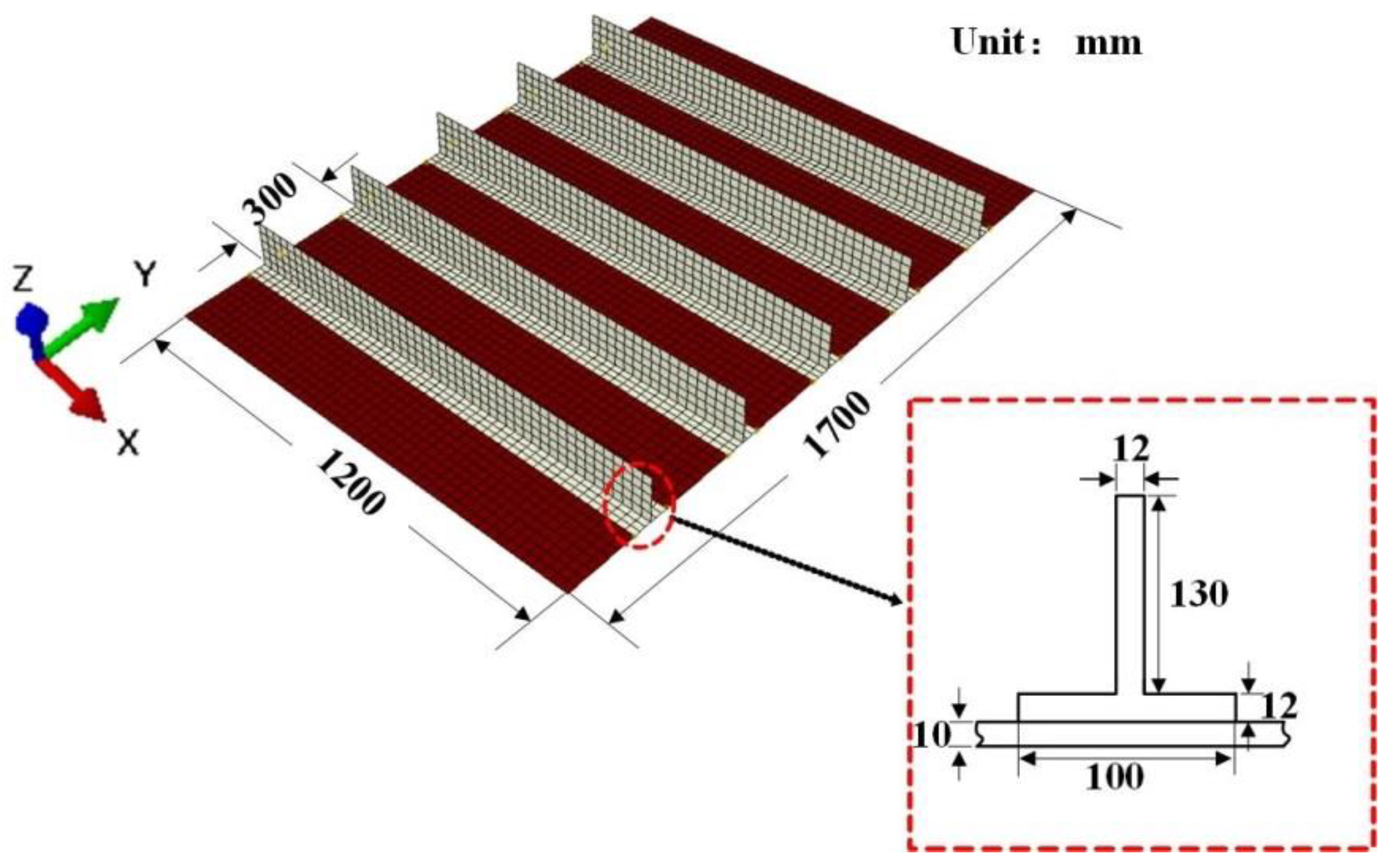
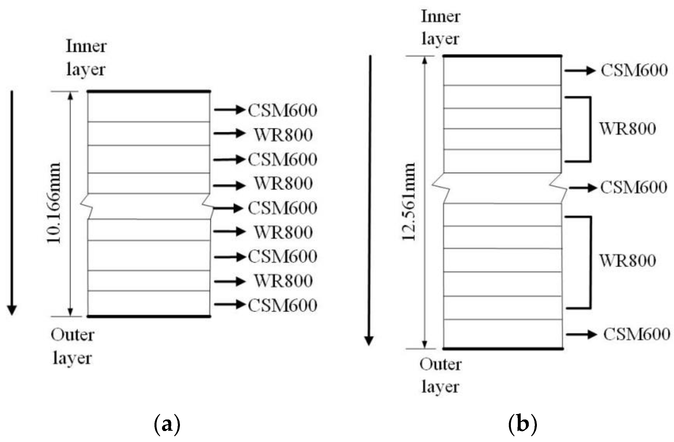
2. Description of the GFRP Stiffened Plate

The GFRP stiffened plate is often used in the deck structure of high-speed ships. Here, the selected stiffened plate dimensions are shown in Figure 1. The longitudinal length of the plate is 1200 mm (frame spacing), the transverse width is 1700 mm, and the plate thickness is 10 mm. The stiffeners are T-bar 130 × 12/100 × 12 mm, and the stiffener spacing is 300 mm c/c. The composite laminates are designed according to the LR rules [1].
The GFRP composite plates are fabricated using the CSM and WR laminates (see Figure 2), and their thicknesses are 1.250 and 0.979 mm, respectively. The weights of CSM and WR are 600 and 800 g/m2, respectively. The mechanical properties of CSM and WR laminates given in LR [2] are summarised in Table 1.

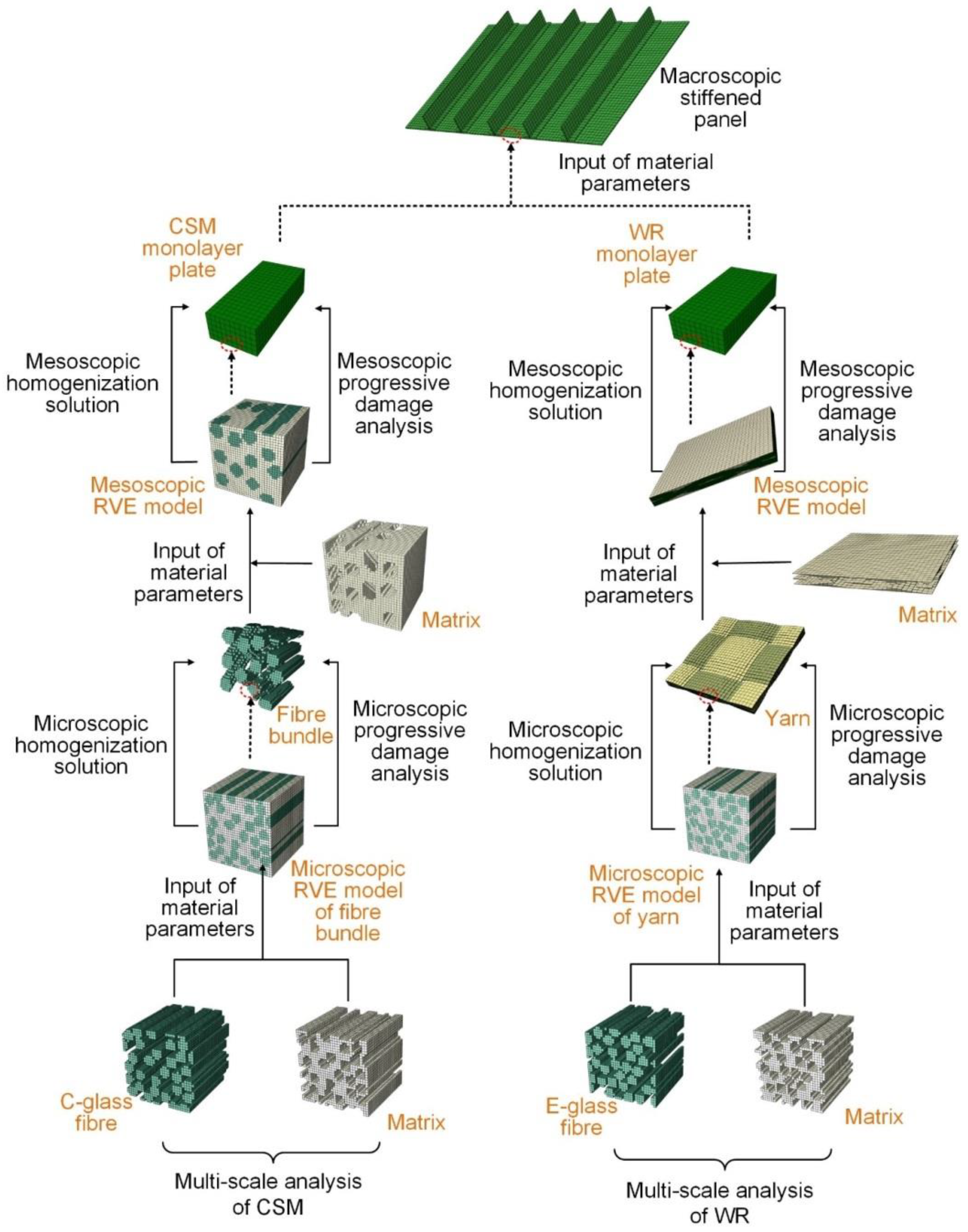
3. Multi-Scale Analysis

The multi-scale analysis procedure was established to assess the mechanical behaviour of GFRP composite stiffened plates, as shown in Figure 3. The finite element method based on the RVE model was used to analyse the micro- and meso-mechanics of CSM and WR composite materials. The micro-scale RVE models defining material micromechanical properties were used to predict the equivalent mechanical properties of the fibre bundle in the CSM and the yarn in the WR laminate by a homogenisation method proposed by Omairey et al. [34]. Afterwards, these equivalent mechanical properties were applied in the meso-scale RVE models to estimate the equivalent mechanical properties of the CSM and WR laminates, respectively, by the homogenisation method. Finally, these analysed properties were used as inputs for structural analysis of GFRP stiffened plates at the macro-scale. The multi-scale methodology is described in the following sections in detail.

3.1. Micro- and Meso-Scale RVE Models

In the multi-scale analysis, the RVE models must be appropriately selected to build the structural form of composite materials. The material components with respective dimensions and mechanical parameters should be well defined to describe the mechanical behaviour in the RVE models.
At the micro-scale, the RVE models of the fibre bundle in the CSM and the yarn in the WR laminate are idealised using the solid unidirectional circular fibre composites with a specific fibre volume fraction [35]. The micro-scale RVE model of the fibre bundle in the CSM laminate consists of C-glass fibre and polyester resin matrix, and the micro-scale RVE model of yarn in the WR laminate consists of E-glass fibre and polyester resin matrix. The fibre is assumed to be transversely isotropic, and the matrix is isotropic [36]. Moreover, it is assumed that the fibres are perfectly bonded to the matrix, not considering voids and micro-cracks.
The meso-scale RVE model of CSM laminates consists of C-glass fibre bundles and polyester resin matrix, and the fibre bundles are distributed randomly in the XY plane. The diameter of fibre bundles is 0.188 mm, and the fibre volume fraction is 0.33. This RVE model is generated by the random sequential adsorption (RSA) technique [37].
The meso-scale RVE model of WR laminates consists of E-glass fibre yarns and polyester resin matrix, and the warp and weft yarns are mutually orthogonal to form the woven structure [36]. The yarn width, thickness, and spacing are 1.88, 0.15, and 2.0 mm, respectively, and the fibre volume fraction is 0.5.
In the micro- and meso-scale RVE models, unified periodical boundary conditions proposed by Xia et al. [38] are applied. Each RVE in the composite has the same deformation mode, and there is no separation or overlap between the neighbouring RVEs. It is defined using the EQUATION keyword in ABAQUS. The voxel meshing model adequately creates the periodical mesh.

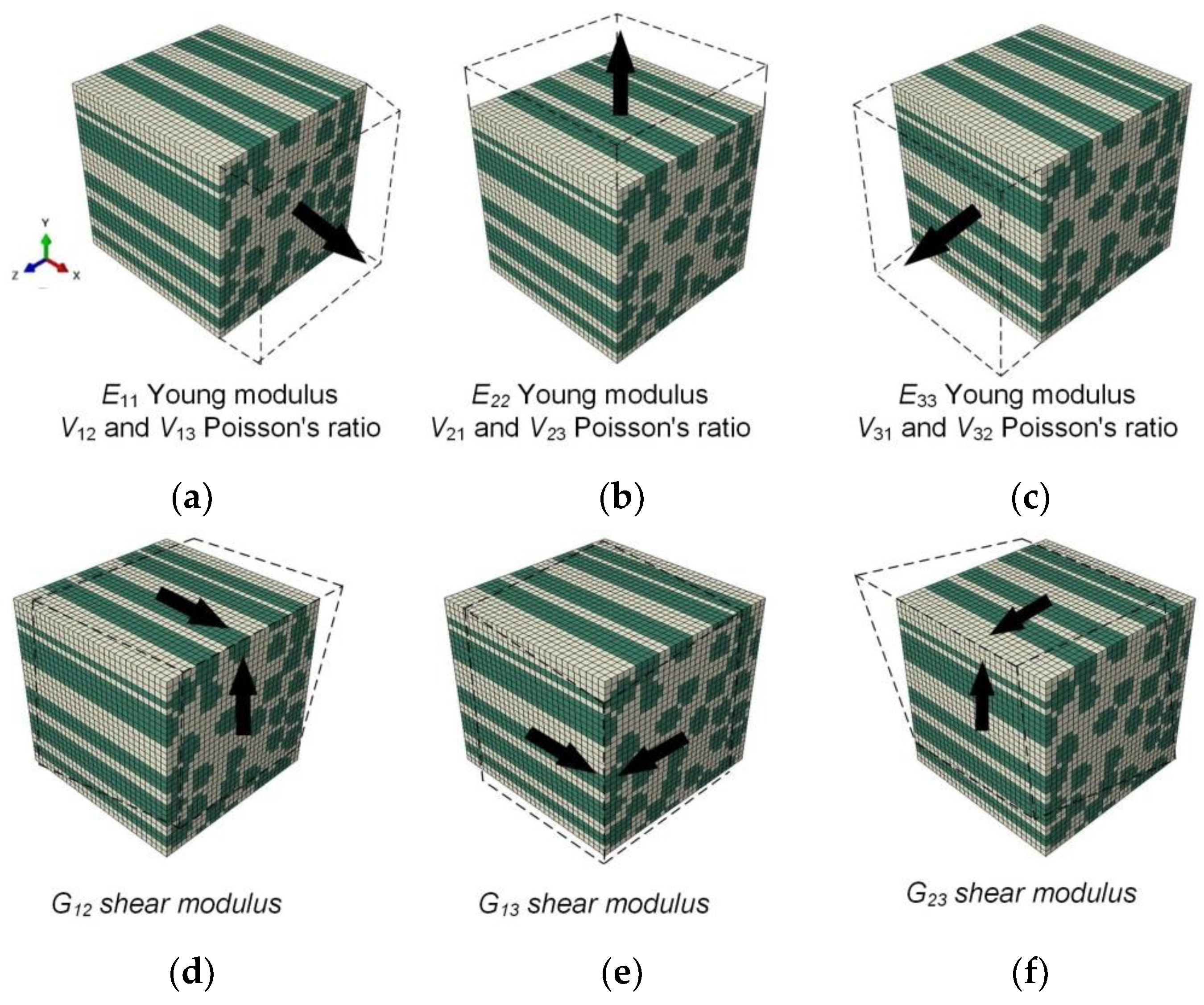
3.2. Elastic Properties of Composites

For the constitutive model of fibre-reinforced composites, it is necessary to determine nine elastic constants. These constants can be calculated by the finite element method based on the RVE model by applying the simple stress/strain states.
The micro-scale RVE model of CSM material defines the micromechanical properties of C-glass fibre and polyester resin matrix. For WR material, E-glass fibre and matrix properties are defined (see Table 2). The basis material parameters are supplied by the manufacturer. The micro-scale finite element analyses, combined with the analytical homogenisation method, are used to predict the material elastic properties of the fibre bundle in CSM and the yarn in WR laminates, respectively.
The RVE models with six sets of different loads and constraints are developed to predict the Young’s moduli (E11, E22, E33), Poisson’s ratios (V12, V13, V23), and shear moduli (G12, G13, G23) under uniaxial loading and corresponding constraints, respectively (see Figure 4). The elastic parameters are calculated by:
E 11 = F 1 L Δ 1 H W ,   E 22 = F 2 H Δ 2 L W ,   E 33 = F 3 W Δ 3 H L
V 12 = Δ 2 L Δ 1 H ,   V 13 = Δ 3 L Δ 1 W ,   V 23 = Δ 3 H Δ 2 W
G 12 = F S 1 W L × 1 Δ S 1 H + Δ S 2 L ,   G 13 = F S 2 H L × 1 Δ S 1 W + Δ S 3 L ,   G 23 = F S 3 H L × 1 Δ S 2 W + Δ S 3 H
where the lengths of the RVEs in X, Y, and Z directions are L, H, and W, respectively; F1, F2, and F3 represent the corresponding forces caused by the applied uniaxial displacements Δ1, Δ2, and Δ3 in X, Y, and Z directions, respectively; FS1, FS2, and FS3 represent the corresponding forces caused by the applied shear displacements ΔS1, ΔS2, and ΔS3.
The homogenised micro-scale material properties are used to define the fibre bundle in CSM and the yarn in WR laminates for the meso-scale finite element analyses, respectively. The same homogenisation method is used to analyse the homogenised meso-scale material properties.

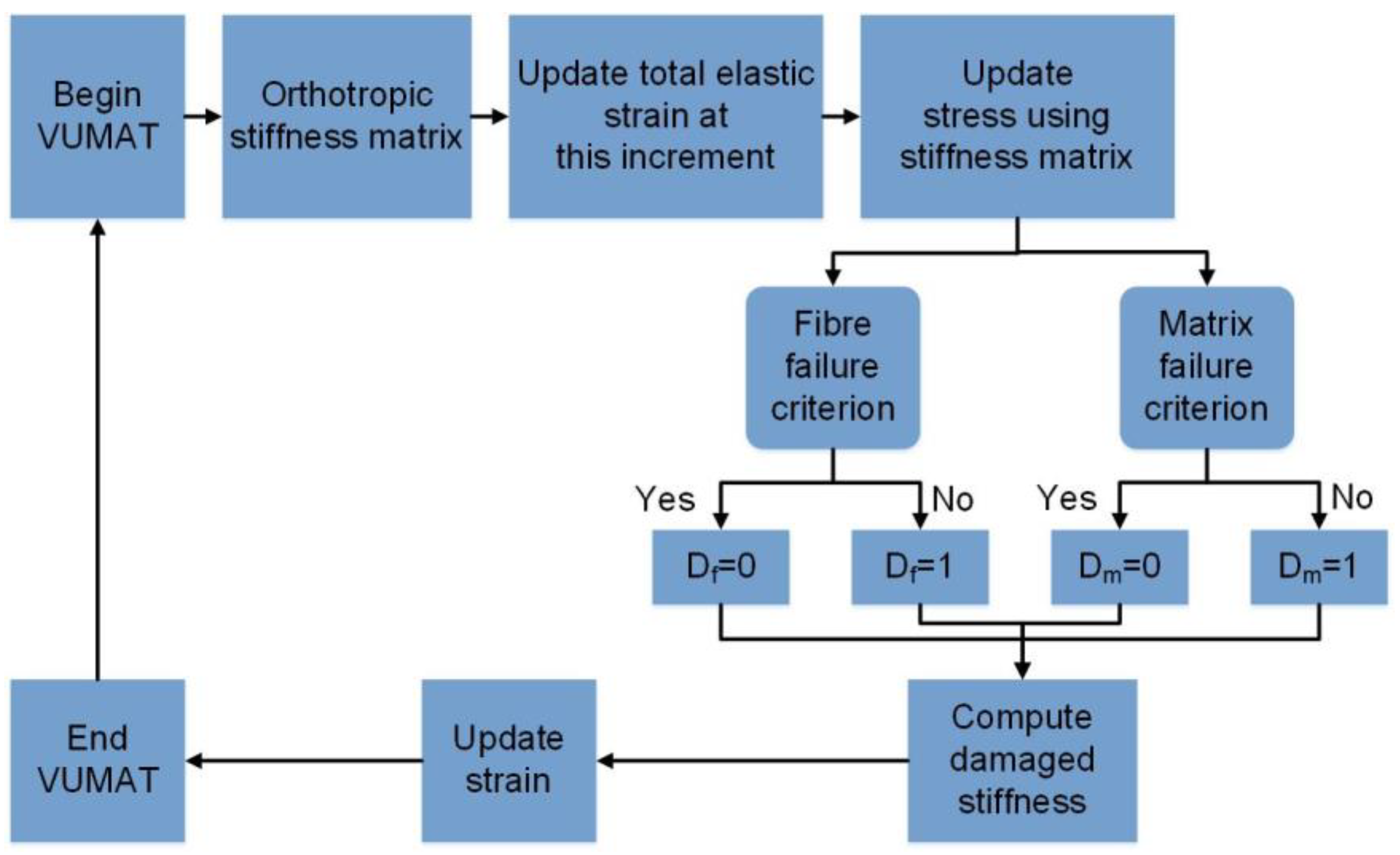
3.3. Failure Criterion and Stiffness Degradation Model

It is essential to select the appropriate failure criteria for assessing the material failures in the micro- and meso-scale. The stiffness degradation of material components is realised through the damage evolution model. The stiffness degradation model should be selected appropriately based on the fibre characteristics to realise the progressive damage process of the RVE model.
The failure criterion and the stiffness degradation model of the micro- and meso-scale components are coded and implemented as a user-defined material subroutine VUMAT for Abaqus/Explicit (Figure 5). The VUMAT subroutine can be used to define the mechanical constitutive behaviour of a material and to update solution-dependent state variables. For example, in the subroutine for defining the fibre bundle of the meso-scale RVE model of CSM, 19 basic material parameters, including elastic moduli and strengths, are input in the GUI (graphical user interface). The variables are judged, calculated, and updated in the VUMAT subroutine, and the updated variables are returned to the main program for computation. The steps to judge the element stress state and calculate and update the damage parameters are the most important to realise the failure criterion and progressive damage evolution in the VUMAT subroutine.

3.3.1. Fibre Failure

In the micro-scale RVE models, a maximum stress criterion is used to describe the failure of fibres. Fibre failure occurs when one of the three principal stresses reaches the ultimate strength.
max σ 1 X , σ 2 Y , σ 3 Z = 1
where σ1, σ2, and σ3 are the principal stresses; X, Y, and Z take the ultimate tensile or compressive strength.
In the meso-scale RVE models, the three-dimensional Hashin criterion captures the damage of fibre bundles and yarns. The material failure is classified into four damage modes.
Fibre tension failure:
σ 1 X T 2 + τ 12 2 + τ 13 2 S 12 2 2 = 1   for   σ 1 0
Fibre compression failure:
σ 1 X C 2 = 1   for   σ 1 < 0
Matrix tension failure:
σ 2 + σ 3 Y T 2 + τ 23 2 σ 2 σ 3 S 23 2 + τ 12 2 + τ 13 2 S 12 2 = 1   for   σ 2 + σ 3 0
Matrix compression failure:
Y C 2 S 23 2 1 σ 2 + σ 3 Y C + σ 2 + σ 3 2 S 23 2 + τ 23 2 σ 2 σ 3 S 23 2 + τ 12 2 + τ 13 2 S 12 2 = 1   for   σ 2 + σ 3 < 0
where σ1, σ2, and σ3 are the principal stresses; τ12, τ13, and τ23 are the shear stresses; XT and YT are the axial and transverse tensile strengths, respectively; XC and YC are the axial and transverse compressive strengths, respectively; S12 and S23 are the in-plane and out-of-plane shear strengths, respectively.

3.3.2. Matrix Failure

In the micro- and meso-scale RVE models, a von Mises criterion is used to describe the failure of the pure matrix.
σ eq σ eq cr n p + I 1 I 1 cr = 1
where σ eq is the equivalent von Mises stress; I1 is the first stress invariant; σ eq cr and I 1 cr are the material constants calculated from the ultimate tensile and compressive strength, respectively; and the exponent n p is taken as 1.0.

3.3.3. Stiffness Degradation

Stiffness is degraded in the process of progressive damage of the RVE model. The material degradation model assumes that the stress–strain relation is linear before the damage, and the stress is degraded instantaneously once the damage occurs.
In the micro-scale RVE model, the reduction factor used in the maximum stress criterion is taken as 0.1. When the fibre failure occurs, the elastic modulus E11 and the Poisson’s ratio V12 are degraded; when the matrix failure occurs, the elastic modulus E22 and the Poisson’s ratio V12 are degraded; when the shear failure occurs, the shear modulus G12 is degraded.
In the meso-scale RVE model, the reduction factor used in the Hashin criterion is taken as 1. When the fibre failure occurs, the elastic modulus E11, shear modulus G12 and Poisson’s ratio V12 are degraded; when the matrix failure occurs, the elastic modulus E22, shear modulus G12 and Poisson’s ratio V12 are degraded; when the shear failure occurs the elastic modulus E11 and E22, shear modulus G12 and Poisson’s ratio V12 are degraded.

4. Micro- and Meso-Scale Analysis Results

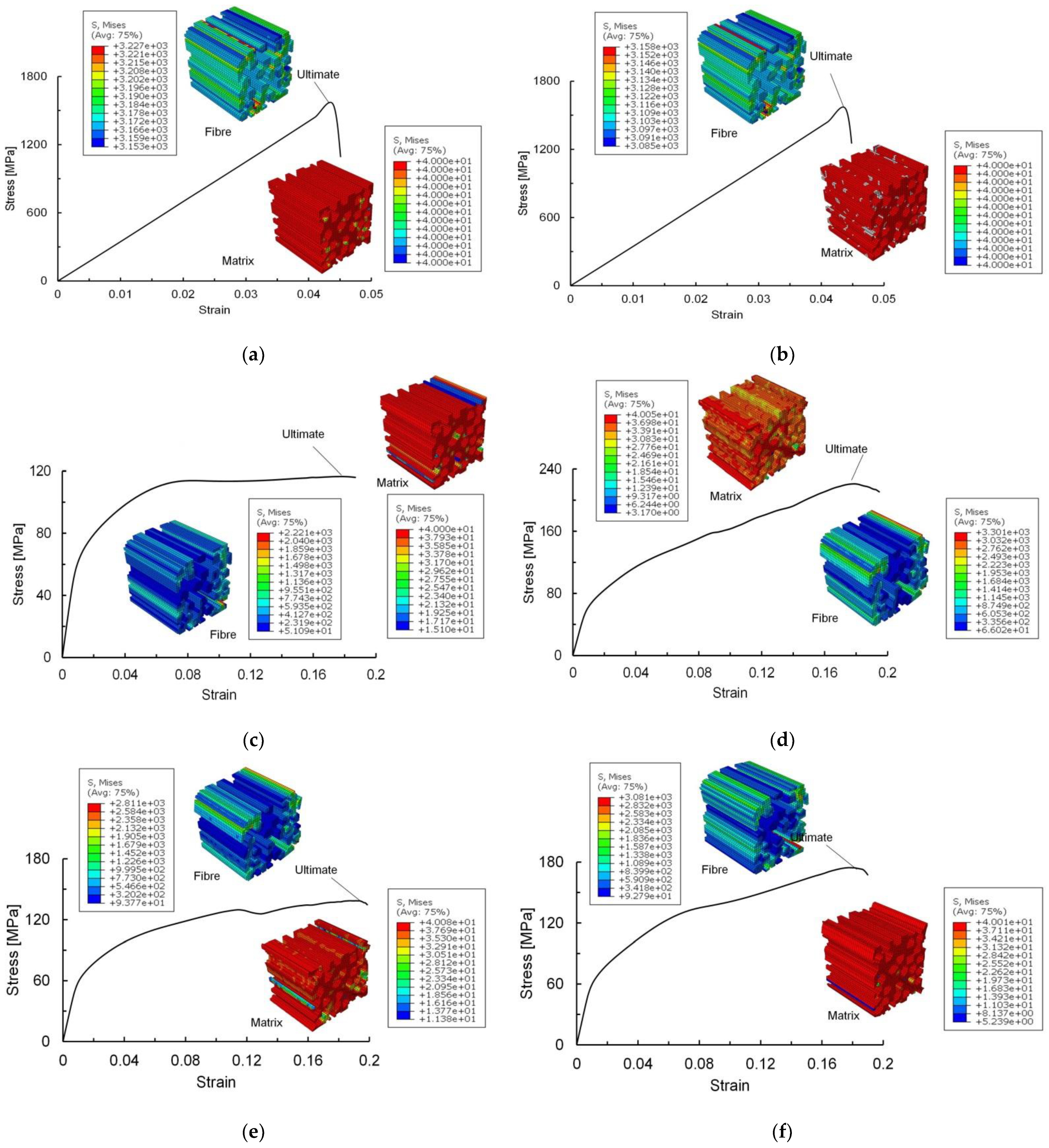
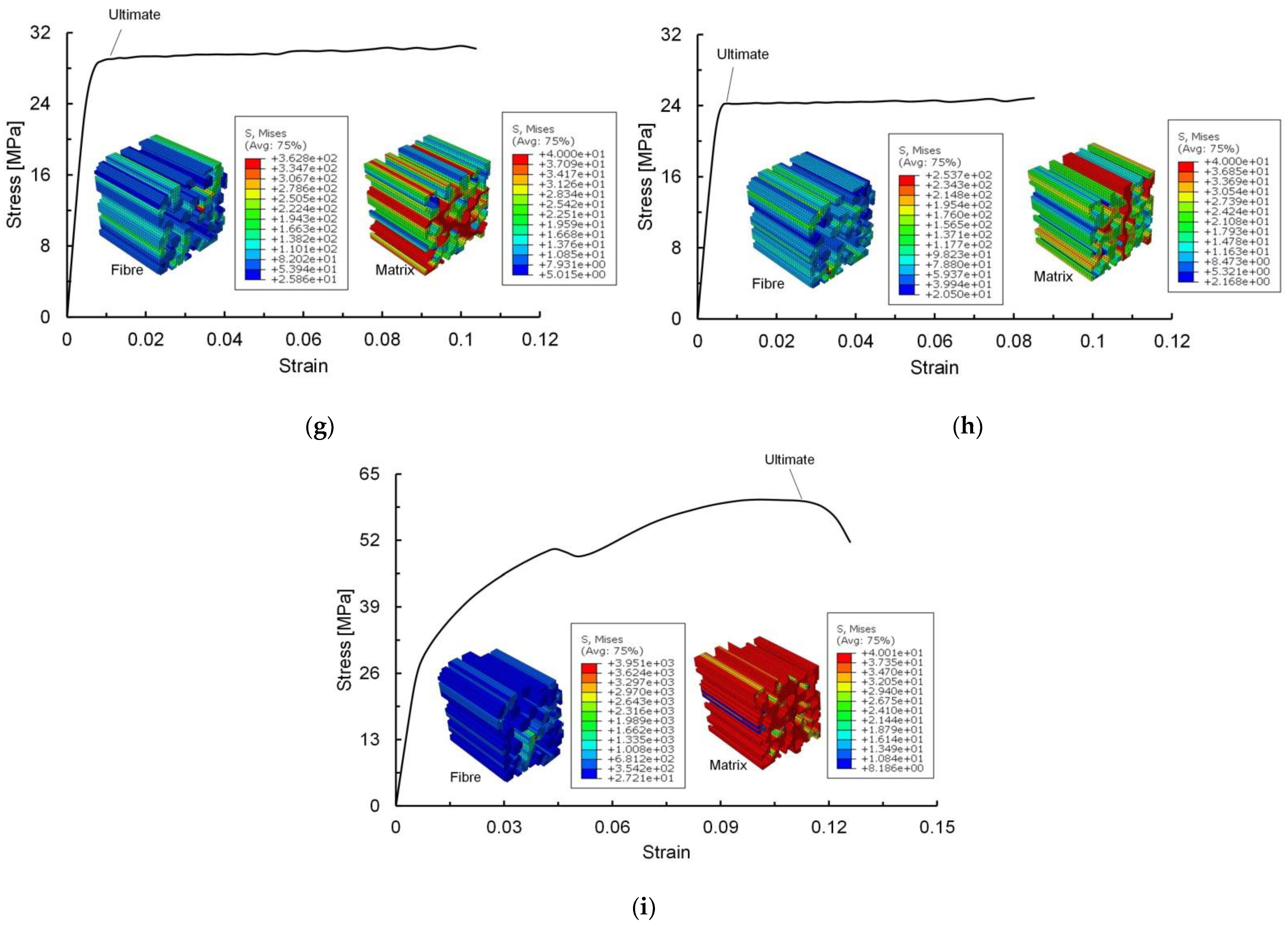
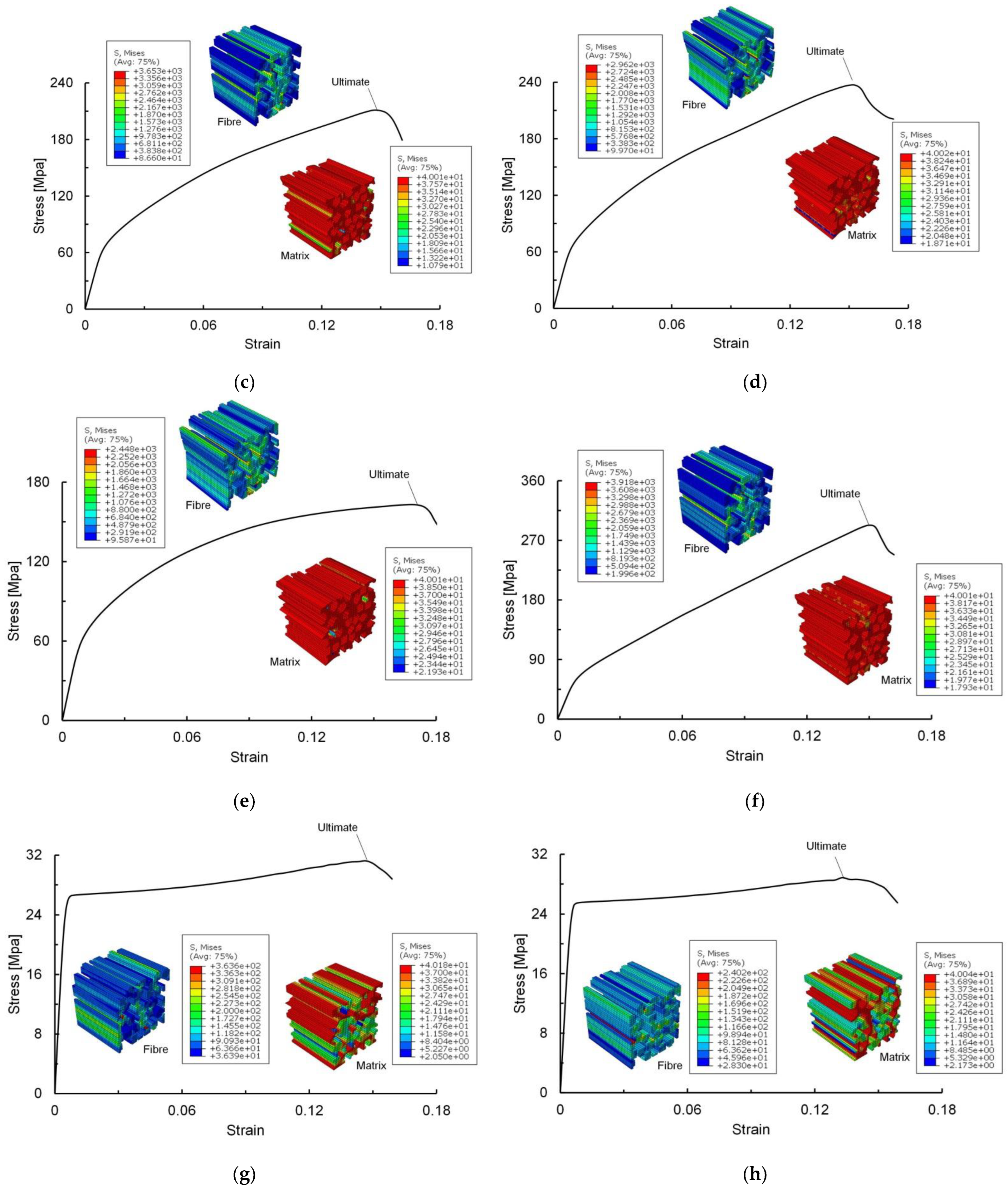
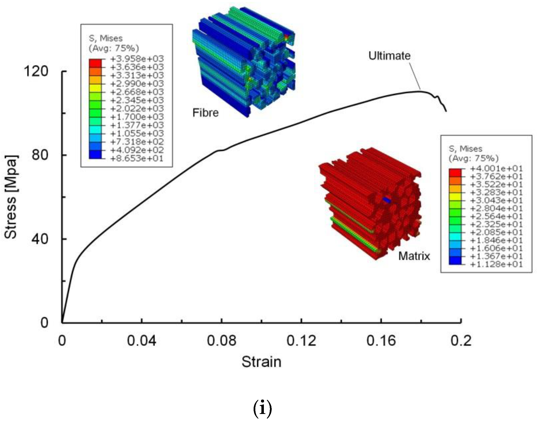
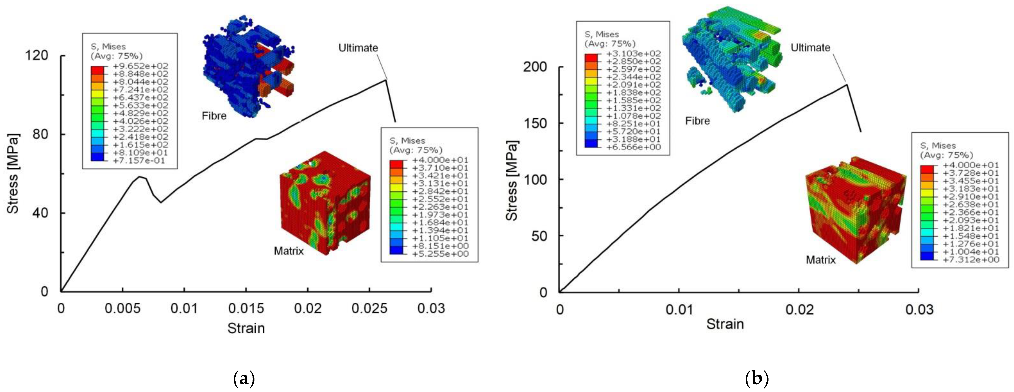
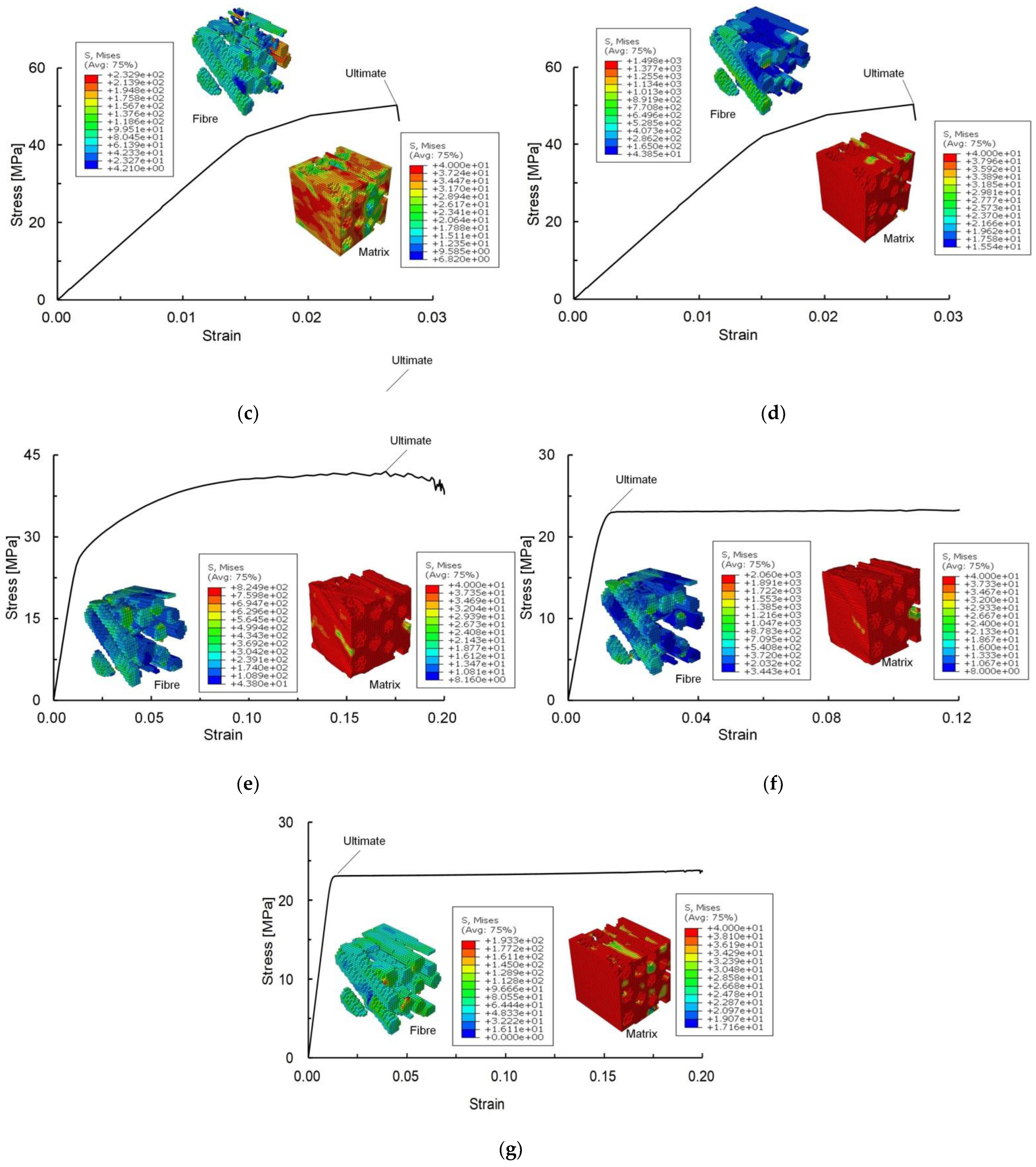
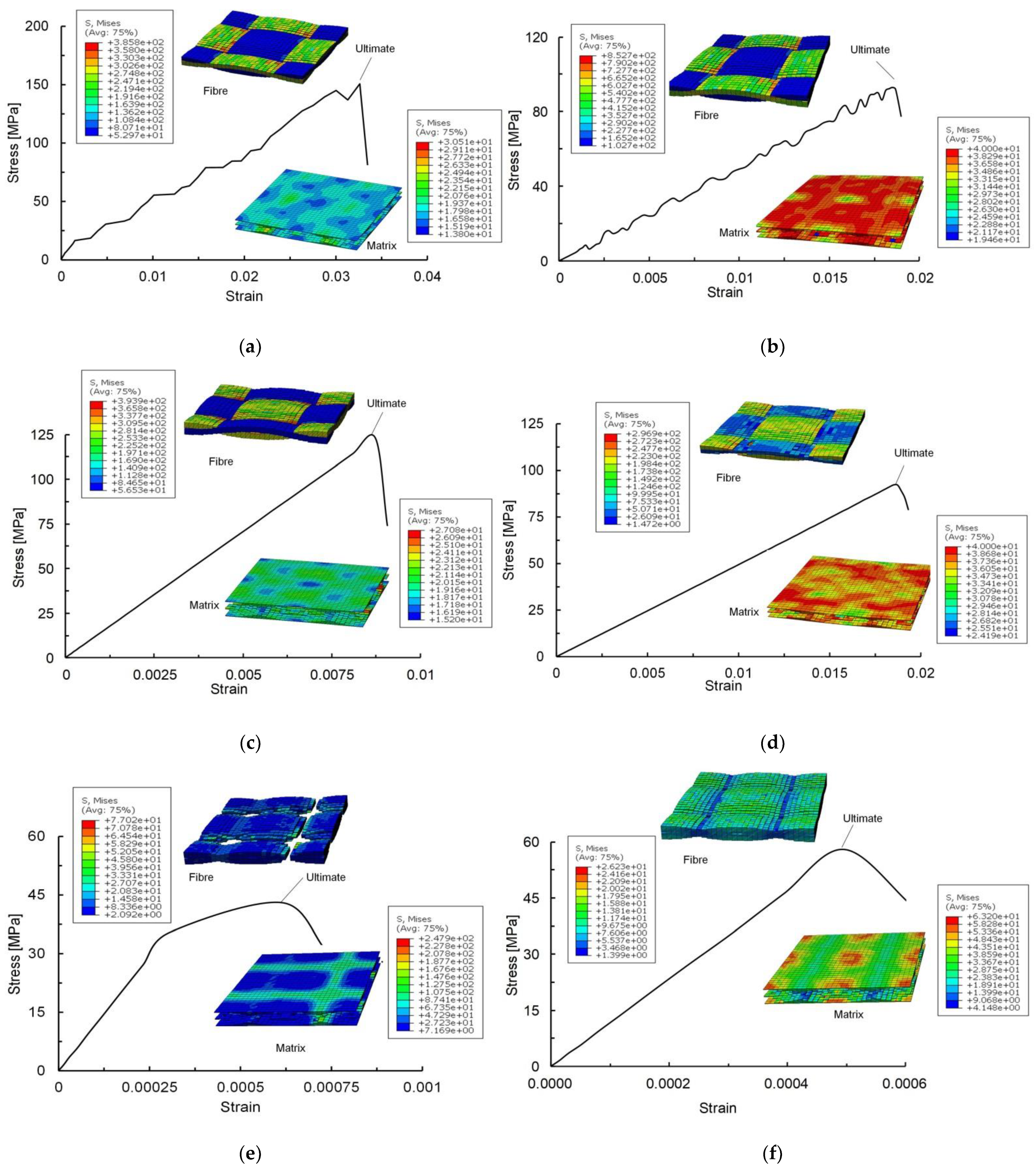
4.1. Micro-Scale Results

The homogenised micro-scale material properties are summarised in Table 3 and Table 4. The equivalent stress-strain curves of micro-scale RVE models of the fibre bundle in CSM under various loads are plotted in Figure 6. The tensile, compressive and shear loads at three directions are applied to the RVE models, respectively. Their von Mises stress plots of fibre and matrix at the limit state are also given in Figure 6. The X-axis is along the fibre direction (axial direction), and Y- and Z-axis are the direction perpendicular to the fibre direction (transverse and vertical direction).
In the CSM fibre bundle under X-tension (Figure 6a), the matrix elements fail first, and the damage volume increases with the tensile load. Subsequently, the fibre elements begin to fail, and the initial damage of fibres occurs mainly at the fibre surface or the lower tensile strength of fibres. When a fibre element is damaged, the load will be carried by its adjacent fibre elements, and it causes the stress in these elements to be larger than the stress in other fibre elements. When the stress reaches a critical condition, the fibre damage will extend in this direction. When the fibre damage propagates through the whole fibre bundle, it causes the complete failure of the RVE model. The ultimate tensile strength of the fibre bundle mainly depends on the fibre’s yield strength.
In the CSM fibre bundle under X-compression (Figure 6b), extensive damage to the matrix occurs when the equivalent strain reaches 0.02. Afterwards, the fibre starts to fail when the equivalent strain reaches 0.05. The break of fibres leads to the loss of the load-carrying capacity of the RVE model, and the fibre damage causes the ultimate compressive strength of the fibre bundle.
In the CSM fibre bundle under Y-tension (Figure 6c), the damage is mainly located at the stress concentration zone caused by the transverse tension. When the matrix between the fibres fails, the fibres and the matrix are separated. Currently, the RVE model is transversely damaged and cannot withstand transverse loads. The fibre bundle is essentially undamaged during the transverse tension, and the matrix damage on the fracture surface causes damage to the fibre bundle.
The matrix damage is randomly distributed in the CSM fibre bundle under Y-compression (Figure 6d) but mainly occurs near the compressive fracture surface. Afterwards, extensive damage occurs at the matrix, and the fibres are almost undamaged under transverse compression. The damage accumulation in the matrix causes eventual damage to the fibre bundle.
The RVE model under Z-tension (Figure 6e) shows a similar damage mode to the one under Y-tension (Figure 6c), and the RVE model under Z-compression (Figure 6f) shows a similar damage mode to the one under Y-compression (Figure 6d).
Similar stress-strain curves and damage modes are obtained in the CSM fibre bundle under XY-shear and XZ-shear (Figure 6g,h). The matrix damage occurs first, followed by the extension of matrix damage in the shear plane, resulting in a nonlinear stress-strain relationship. When the equivalent strain reaches 0.01, the matrix fails at the fracture zone, and the interface cannot carry the force transmission between the fibres and the matrix. It results in permanent damage and the separation of the fibres from the matrix. The permanent shear damage of the fibre bundle is mainly due to the matrix damage on the fracture surface.
The matrix damage €s mainly located at the shear surface in the CSM fibre bundle under YZ-shear (Figure 6i). The equivalent stress drops abruptly when the matrix between the fibres fails on the shear surface. It indicates that the matrix damage strongly affects the stress-strain relationship. With the increase in matrix damage, the fibres and the matrix separate, determining the shear damage. The structure cannot continue to withstand the shear loading. The fibre bundle is essentially undamaged under YZ-shear. The shear damage of the fibre bundle is caused by the matrix damage at the fracture surface and the separation of the fibres and matrix.
For the micro-scale RVE models of yarn in WR under various loads, the equivalent stress-strain curves and damage modes of micro-scale RVE models are plotted in Figure 7. Their characteristics are very similar to the ones in CSM, and thus they are not described here.

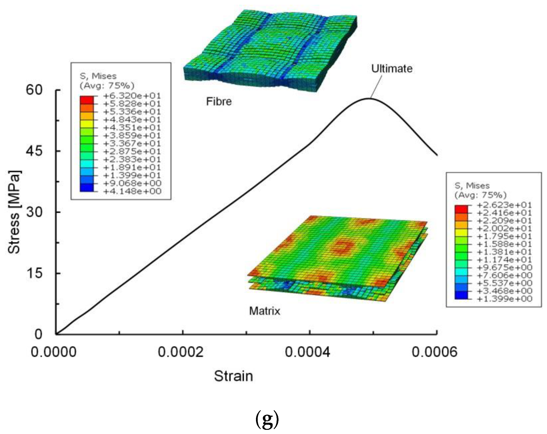
4.2. Meso-Scale Results

The homogenised meso-scale material properties are given in Table 3 and Table 4. The analysed equivalent stress-strain curves of meso-scale RVE models under axial tension, axial compression, transverse tension, transverse compression, in-plane shear, and out-of-plane shear loadings for CSM and WR laminates are shown in Figure 8 and Figure 9, respectively. In all of the stress plots of CSM and WR materials, the stresses are mainly concentrated around the fibre bundles, i.e., the fibre bundles are the principal load-carrying component. Their von Mises stresses at the ultimate loading are also plotted in Figure 8 and Figure 9.

4.2.1. CSM Material

In the RVE model of CSM material under X-tension (Figure 8a), the pure matrix does not suffer any failure at the initial stage. A decrease in equivalent stress is observed at the equivalent strain of 0.006 due to matrix tensile failure in the fibre bundles. As the stress increases, the pure matrix fails, and the fibre bundles show fibre tensile failure, causing material stiffness degradation. Finally, permanent damage to composite material occurs, indicating the ultimate tensile strength. The damaged evolution of fibre bundles and pure matrix leads to a decrease in load-carrying capacity.
In the RVE model of CSM material under X-compression (Figure 8b), only a small amount of matrix compression damage occurs in the fibre bundle at the initial stage, which does not affect the global equivalent stress. The ultimate compressive load is reached because extensive matrix compression damage occurs in the fibre bundles.
In the CSM material under Y-tension (Figure 8c), only a tiny amount of damage occurs initially at the pure matrix, slightly affecting the global equivalent stiffness. When the equivalent strain reaches 0.019, the stiffness decreases due to extensive damage at the pure matrix. With the increase in the equivalent strain reaching 0.027, the tensile damage of the matrix occurs in the fibre bundles, and the ultimate tensile load is reached. The damage evolution of the fibre bundles and pure matrix leads to the reduction of structural load-carrying capacity.
The pure matrix suffers compressive damage in the CSM material under Y-compression (Figure 8d). When the equivalent strain reaches 0.02, the compressive damage of the matrix occurs in the fibre bundles decreasing the material stiffness. The compressive matrix damage in the fibre bundles expands with the increase in equivalent strain, and the RVE model loses its load-carrying capacity when the equivalent strain reaches 0.027. The evolution of matrix compression damage in the fibre bundles leads to the reduction of load-carrying capacity.
In the CSM material under XY-shear and XZ-shear (Figure 8e,f), the damage occurs at the pure matrix first, mainly concentrated around the shear fracture plane. When the mean strain reaches 0.012, the pure matrix between fibre bundles fails on the shear fracture plane leading to the stiffness reduction. As the pure matrix damage increases, the fibre bundles and pure matrix separate, determining the RVE model’s shear failure. The damage mode under YZ-shear (Figure 8g) is similar to that under XZ-shear (Figure 8f).

4.2.2. WR Material

In the RVE model of WR material under X-tension (Figure 9a), the stress-strain relationship is strongly nonlinear due to the random distribution of pure matrix damage. When the equivalent strain reaches 0.0075, the pure matrix continues to damage, resulting in stiffness reduction. When the equivalent strain reaches 0.008, the matrix tensile damage occurs at the yarns in the fibre bundle direction and permanent damage to the RVE model occurs. The permanent damage is located at the cross of the warp and weft yarns.
The pure matrix damage distribution is random in the WR material under X-compression (Figure 9b). When the equivalent strain reaches 0.009, the matrix compression damage occurs in the warp yarns parallel to the X-direction. With the increase in equivalent stress, the matrix compression damage of the warp yarns extends to the weft yarns. The permanent damage of the RVE model occurs at the cross of warp and weft yarns.
The RVE model under Y-tension (Figure 9c) shows a similar damage mode to the one under X-tension (Figure 9a), and the RVE model under Y-compression (Figure 9d) shows a similar damage mode to the one under X-compression (Figure 9b).
In the WR material under XY-shear (Figure 9e), the initial damage occurs in the pure matrix. An abrupt change in stiffness occurs at the equivalent strain of 0.00023, and the stress is mainly concentrated in the yarns. With the increase in equivalent stress, fibre shear damage occurs in the yarns, and the stress is mainly concentrated at the cross of the warp and weft yarns. When the equivalent strain reaches 0.00062, the RVE model suffers shear damage and cannot withstand the shear load.
In the WR material under XZ-shear (Figure 9f), when the equivalent strain reaches 0.0004, the stresses are concentrated at the yarns, and the stiffness changes abruptly. Afterward, the yarn damage increases, leading to the complete shear damage of the RVE model when the equivalent strain reaches 0.0005. The damage mode under YZ-shear (Figure 9g) is similar to that under XZ-shear (Figure 9f).

4.2.3. Mean Material Properties for Macro-Scale Analysis

In the macro-scale CSM materials, the fibre bundles are distributed randomly in the XY- plane, and the CSM material is regarded as a quasi-isotropic material in the macro-scale. The macro-scale WR materials with 0/90° braiding are transversely isotropic. CSM and WR materials can be considered the same elastic constants, tensile, and compressive strength in X and Y directions. In addition, it is considered the same shear strength in XZ and YZ directions. Thus, the macro-scale material properties of CSM and WR materials (Table 5 and Table 6) can be obtained by averaging the corresponding meso-scale analysis results (Table 3 and Table 4).
The mean material properties (Table 5 and Table 6) define the macro-mechanical properties of the CSM and WR materials in the GFRP stiffened plates. The macro-mechanical strengths of CSM and WR materials obtained from the meso-scale analysis follow LR’s material properties [2]. The rules require that the calculated values of material properties cannot be larger than the given values. This requirement is satisfied when comparing the values from the meso-scale analysis (Table 5 and Table 6) with the rule values (Table 1). It proves the accuracy of the multi-scale analysis method.

5. Macro-Scale Analysis of GFRP Stiffened Panel

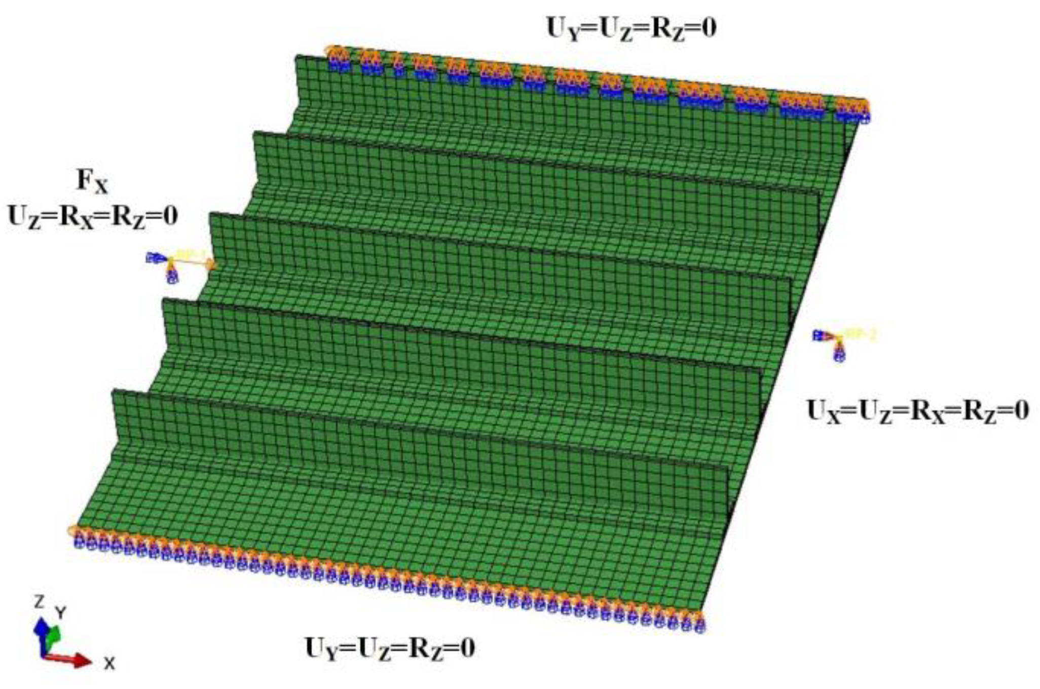
5.1. Numerical Modelling

The finite element model is generated using rectangular four-node shell elements (S4R) selected from the ABAQUS element library. The element size is selected at about 25 mm, and this mesh density is sufficient to accurately capture the global and local buckling of plates and stiffeners. The finite element model consists of 6811 nodes and 6384 shell elements.
The mean mechanical properties of CSM and WR materials (Table 5 and Table 6) are used as the input parameters for the finite element analysis of the ultimate strength of the GFRP stiffened panel. Quads criterion is used to judge the interface debonding failure, and the two-dimensional Hashin criterion is used to judge the fibre and matrix failure. Bonding between the stiffener and the plate is simulated using cohesive elements, and the properties of cohesive elements are shown in Table 7. The energy-dependent damage evolution model is also defined, and the defined values are given in Table 8. The authors validate the way to define material properties by comparing experimental results given in Ref. [39] with an error of 8% in ultimate strength prediction.
The definitions of boundary conditions are shown in Figure 10. For the loaded edge, the Z-displacement and X- and Z-rotation are constrained, and for the reactive edge, the X- and Z-displacement and X- and Z-rotation are constrained. The Y- and Z-displacement and Z-rotation are constrained at all the nodes along the unloaded edges. A uniaxial load is applied at all the nodes along the loading edge, and the ultimate load of the stiffened panel is determined from the peak value of the uniaxial load. This boundary condition is widely used in the ultimate compressive analysis of stiffened panels [40,41,42,43].

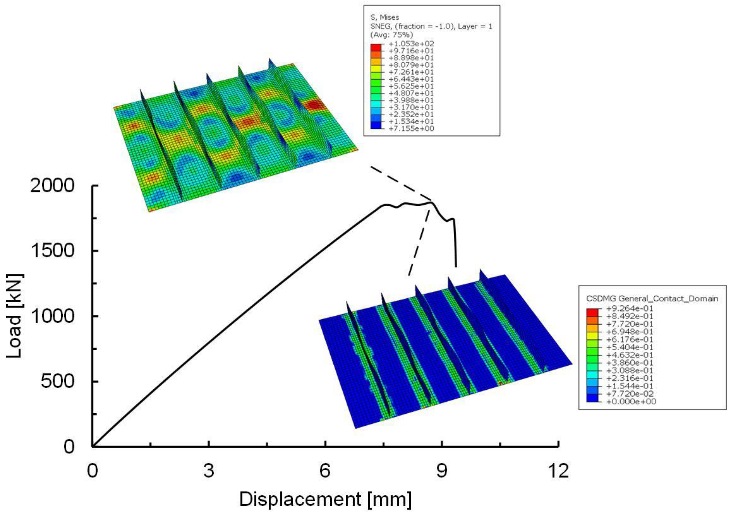
5.2. Numerical Results

The load-displacement curve of the GFRP stiffened plate is shown in Figure 11. The plots of the von Mises stresses and the complete debonding failure of the bonding layer at the ultimate load are also given in Figure 11.
The stiffened panel collapses due to global buckling and local damage. The stiffened panel loses its carrying capacity when reaching the peak force. It is shown that the bonding layer of the stiffeners and plate is the weakest region, and the damage process involves matrix damage, fibre damage and debonding failure. Fibre damage is the most important factor leading to stiffened panel collapsing.

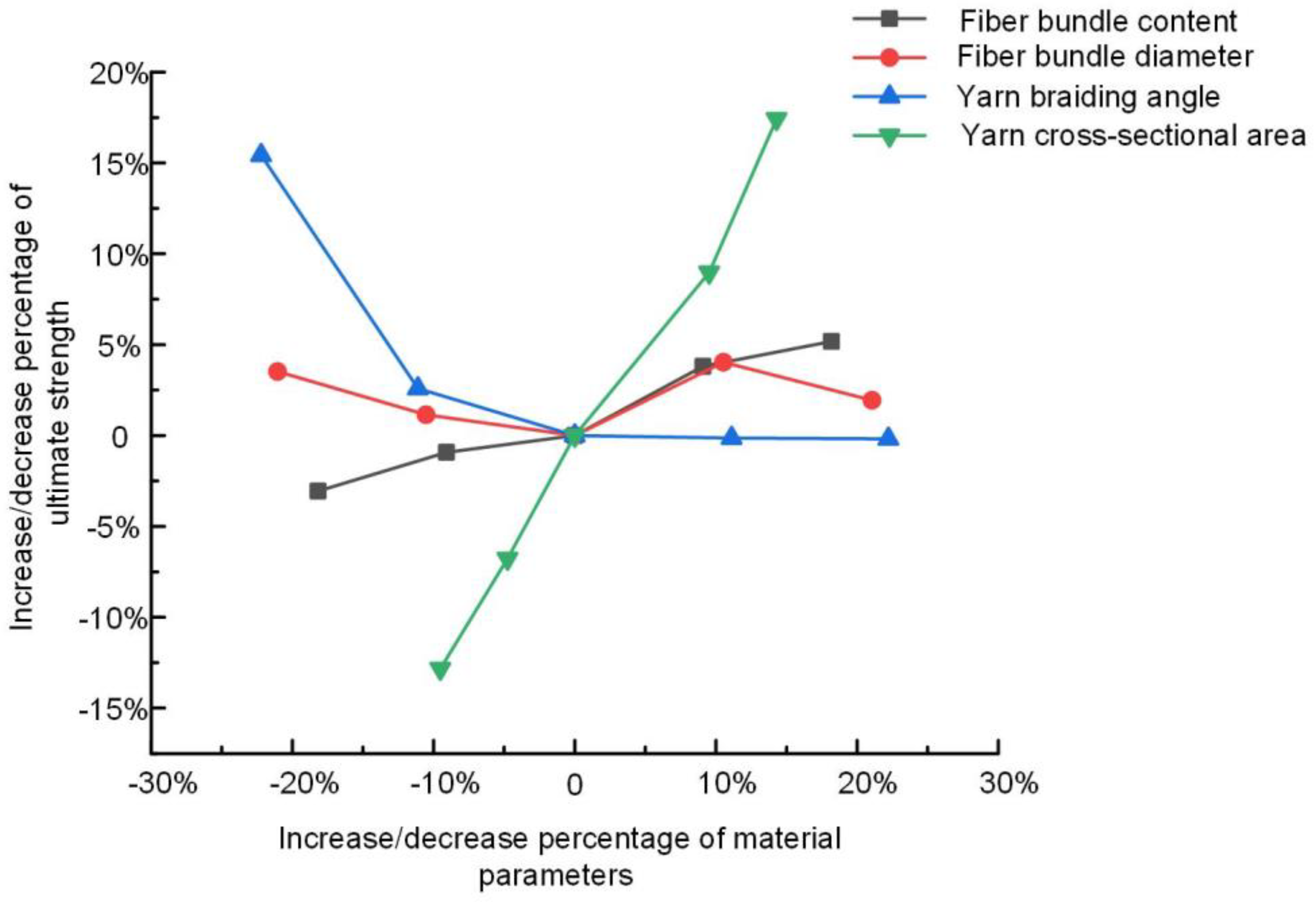
6. Parametric Analysis

Material parameters of meso-scale components strongly affect the ultimate strength of macro-scale composite stiffened panels. Twenty sets of meso-scale RVE models are analysed with different volume fractions and diameters of the fibre bundle in CSM, braiding angle and cross-sectional area of yarn in WR. The material parameters of meso-scale components are given in Table 9. The effect of meso-scale material parameters on macro-stiffened panels’ ultimate strength is shown in Figure 12.
It can be seen that the ultimate macro strength increases with the volume fraction of the fibre bundle in CSM since the damage of fibre bundles mainly causes the ultimate strength of the macro stiffened panel (black line in Figure 12). However, it is not easy to achieve the high-volume fraction of fibre bundles in the fabrication due to the reduction of matrix proportion. If the matrix cannot be well bonded in the fabrication, the load transmission of the matrix will be reduced in the composite materials.
The larger diameter of fibre bundles in CSM implies the higher load-carrying capacity of the macro stiffened panel (read line in Figure 12). However, when the volume fraction of the fibre bundle is fixed, the larger diameter of fibre bundles implies a smaller number of fibre bundles. It causes a decrease in the ultimate macro strength. Therefore, a reasonable fibre bundle diameter (0.21 mm) should be selected to obtain the optimal macro ultimate strength in the current study.
In WR materials, warp and weft yarns are interwoven at a certain angle to form a woven structure. For the macro-scale stiffened plate under compression, the braiding angle affects the angle of the yarn with the compressive direction. The yarns are easier to collapse under the combined compressive and shear load, and it reduces the material load-carrying capacity decreasing the ultimate macro strength (blue line in Figure 12). However, the economic cost of small-angle braiding is high, and a reasonable braiding angle needs to be selected, keeping the balance of economic cost and mechanical property.
When the number of yarns is the same for WR materials, the larger cross-sectional area of yarns leads to higher macro ultimate strength, and the relationship is almost linear (green line in Figure 12). Nevertheless, it reduces the effect of bonding and load transfer of the matrix.

7. Conclusions

The multi-scale analysis of composite materials has been carried out to assess the ultimate strength of GFRP stiffened panels, and the effect of material composition and weave on the ultimate strength of marine GFRP stiffened panels has been investigated. The investigation is beneficial to the lightweight design of marine composite structures by selecting the optimal construction materials.
The micro-meso progressive damage model can be used to evaluate the micro-meso mechanical response and damage evolution process. The fibres are the primary load carrying material, and the matrix plays the role of stress transfer. The damage of fibre bundles mainly causes the macro composite stiffened plate damage.
To analyse the effect of meso-scale material parameters on the macro ultimate strength of composite structures, four sensitive parameters have been assessed: the volume fraction and the diameter of the fibre bundle in CSM, the braided angle, and cross-sectional area of yarn in WR. The parametric analysis can be used to select the optimal macro ultimate strength of the composite stiffened panel fabricated by rational material processing technology. Furthermore, the established analysis procedure can be applied to propose the composite material design method to improve the ultimate strength of GFRP panel structures in composite vessels.

Author Contributions

Conceptualisation, B.L. and X.Z.; methodology, B.L. and X.Z.; formal analysis, X.Z.; writing—original draft preparation, B.L. and X.Z.; writing—review and editing, B.L. and Y.G.; supervision, B.L.; funding acquisition, B.L. All authors have read and agreed to the published version of the manuscript.

Funding

This research was funded by the National Natural Science Foundation of China, grant number 52271326 and the Fundamental Research Funds for the Central Universities, grant number WUT: 2021III023JC; WUT: 2021III011XZ.

Institutional Review Board Statement

Not applicable.

Informed Consent Statement

Not applicable.

Data Availability Statement

Data presented in this article are available on request from the corresponding author.

Conflicts of Interest

The authors declare no conflict of interest.

References

  1. L.R. (Lloyd’s Register). Rules and Regulations for the Classification of Special Service Craft; Lloyd’s Register: London, UK, 2020. [Google Scholar]
  2. L.R. (Lloyd’s Register). Rules for the Manufacture, Testing and Certification of Materials; Lloyd’s Register: London, UK, 2020. [Google Scholar]
  3. Zhou, X.Y.; Qian, S.Y.; Wang, N.W.; Xiong, W.; Wu, W.Q. A review on stochastic multi-scale analysis for FRP composite structures. Compos. Struct. 2022, 284, 115132. [Google Scholar] [CrossRef]
  4. Gao, Z.; Chen, L. A review of multi-scale numerical modeling of three-dimensional woven fabric. Compos. Struct. 2021, 263, 113685. [Google Scholar] [CrossRef]
  5. Luan, S.F.; Li, H.Z.; Jia, Y.X.; An, L.J.; Han, Y.C.; Xiang, Q.; Zhao, J.; Li, J.X.; Han, C.C. Analysis of micro-failure behaviors in hybrid fiber model composites. Polymer 2006, 47, 6218–6225. [Google Scholar] [CrossRef]
  6. Zhang, B.M.; Yang, Z.; Sun, X.Y.; Tang, Z.W. A virtual experimental approach to estimate composite mechanical properties: Modeling with an explicit finite element method. Comput. Mater. Sci. 2010, 49, 645–651. [Google Scholar] [CrossRef]
  7. Kurnatowski, B.; Matzenmiller, A. Coupled two scale analysis of fiber reinforced composite structures with microscopic damage evolution. Int. J. Solids Struct. 2012, 49, 2404–2417. [Google Scholar] [CrossRef] [Green Version]
  8. Zhao, L.; Zhang, B.M.; Qing, X.L.; Xie, H.M. In-plane shear properties and damage process of composites based on unit cell analytic model. Acta Mater. Compos. Sin. 2013, 30, 153–157. [Google Scholar] [CrossRef]
  9. Qi, L.H.; Tian, W.L.; Zhou, J.M. Numerical evaluation of effective elastic properties of composites reinforced by spatially randomly distributed short fibers with certain aspect ratio. Compos. Struct. 2015, 131, 843–851. [Google Scholar] [CrossRef]
  10. Chen, Z.X.; Huang, T.Y.; Shao, Y.M.; Li, Y.; Xu, H.Y.; Avery, K.; Zeng, D.; Chen, W.; Su, X.M. Multi-scale finite element modeling of sheet moulding compound (SMC) composite structure based on stochastic mesostructure reconstruction. Compos. Struct. 2018, 188, 25–38. [Google Scholar] [CrossRef]
  11. Turon, A.; Costa, J.; Maim, P.; Trias, D.; Mayugo, J.A. A progressive damage model for unidirectional fibre-reinforced composites based on fibre fragmentation. Part I: Formulation. Compos. Sci. Technol. 2005, 65, 2039–2048. [Google Scholar] [CrossRef]
  12. Li, Y.Y.; Long, S.Y.; Cui, J.Z. Finite element computation for mechanics parameters of composite material with randomly distributed multi-scale grains. Eng. Anal. Bound. Elem. 2008, 32, 290–298. [Google Scholar] [CrossRef]
  13. Lee, H.K.; Kim, B.R. Elastoplastic modeling of circular fiber-reinforced ductile matrix composites considering a finite RVE. Int. J. Solids Struct. 2010, 47, 827–836. [Google Scholar] [CrossRef] [Green Version]
  14. Tian, W.L.; Qi, L.H.; Zhou, J.M.; Liang, J.H.; Ma, Y.Q. Representative volume element for composites reinforced by spatially randomly distributed discontinuous fibers and its applications. Compos. Struct. 2015, 131, 366–373. [Google Scholar] [CrossRef]
  15. Ivancevic, D.; Smojver, I. Explicit multi-scale modelling of impact damage on laminated composites–part II: Multi-scale analyses. Compos. Struct. 2016, 145, 259–268. [Google Scholar] [CrossRef]
  16. Ivancevic, D.; Smojver, I. Micromechanical damage modelling using a two-scale method for laminated composite structures. Compos. Struct. 2014, 108, 223–233. [Google Scholar] [CrossRef]
  17. Li, X.; Guan, Z.D.; Li, Z.S.; Liu, L. A new stress-based multi-scale failure criterion of composites and its validation in open hole tension tests. Chin. J. Aeronaut. 2014, 6, 1430–1441. [Google Scholar] [CrossRef] [Green Version]
  18. Liu, Z.; Zhu, C.; Zhu, P. Generation of random fiber distribution for unidirectional fiber reinforced composites based on particle swarm optimiser. Polym. Compos. 2019, 40, 1643–1653. [Google Scholar] [CrossRef]
  19. Jiao, Z.W.; Zhou, C. Multi-scale mechanical analysis of tridimensional woven composite pipe. Acta Mater. Compos. Sin. 2010, 27, 122–128. Available online: https://fhclxb.buaa.edu.cn/en/article/id/10246 (accessed on 1 May 2010).
  20. Dinh, T.D.; Rezaei, A.; Daelemans, L.; Mollaert, M.; Van Hemelrijck, D.; Van Paepegem, W. A hybrid micro-meso-scale unit cell model for homogenisation of the nonlinear orthotropic material behavior of coated fabrics used in tensioned membrane structures. Compos. Struct. 2017, 162, 271–279. [Google Scholar] [CrossRef]
  21. Zhou, L.C.; Chen, M.W.; Liu, C.; Wu, H.A. A multi-scale stochastic fracture model for characterising the tensile behavior of 2D woven composites. Compos. Struct. 2018, 204, 536–547. [Google Scholar] [CrossRef]
  22. Zhang, C.; Xu, X.W.; Mao, C.J. Progressive damage simulation and strength prediction of 3D braided composites. Acta Mater. Compos. Sin. 2011, 28, 222–230. Available online: https://fhclxb.buaa.edu.cn/en/article/id/10523 (accessed on 1 February 2011).
  23. Shen, X.L.; Gong, L.D. Numerical modeling of braided composites using energy method. In Proceedings of the ASME 2014 International Mechanical Engineering Congress and Exposition, Montreal, QC, Canada, 14–20 November 2014. [Google Scholar]
  24. Yu, X.G.; Cui, J.Z. The prediction on mechanical properties of 4-step braided composites via two-scale method. Compos. Sci. Technol. 2008, 67, 471–480. [Google Scholar] [CrossRef]
  25. Lu, Z.X.; Xia, B.; Wang, C.Y. Progressive damage simulation and strength prediction of three-dimensional and six-directional braided composites. Acta Mater. Compos. Sin. 2013, 30, 166–173. Available online: https://fhclxb.buaa.edu.cn/en/article/id/11976 (accessed on 1 May 2013).
  26. Liang, B.; Zhang, W.; Fenner, J.S.; Gao, J.; Shi, Y.; Zeng, D.; Su, X.; Liu, W.; Cao, J. Multi-scale modeling of mechanical behavior of cured woven textile composites accounting for the influence of yarn angle variation. Compos. Part A Appl. Sci. Manuf. 2019, 124, 105460. [Google Scholar] [CrossRef]
  27. Zhang, Y.F.; Guo, Q.W.; Chen, X.M.; Xie, J.B.; Chen, L. Effect of apertures on tensile property of warp-reinforced 2.5D woven composites notched plates. . Compos. Struct. 2020, 252, 112693. [Google Scholar] [CrossRef]
  28. Smilauer, V.; Hoover, C.G.; Bazant, Z.P. Multi-scale simulation of fracture of braided composites via repetitive unit cells. Eng. Fract. Mech. 2011, 78, 901–918. [Google Scholar] [CrossRef]
  29. Zhao, Z.Q.; Dang, H.Y.; Zhang, C.; Yun, G.J.; Li, Y.L. A multi-scale modeling framework for impact damage simulation of triaxially braided composites. Compos. Part A Appl. Sci. Manuf. 2018, 110, 113–125. [Google Scholar] [CrossRef]
  30. Gao, X.; Yuan, L.; Fu, Y.; Yao, X.; Yang, H. Prediction of mechanical properties on 3D braided composites with void defects. Compos. Part B Eng. 2020, 197, 108164. [Google Scholar] [CrossRef]
  31. Fu, Y.; Yao, X.; Gao, X. Micro-mesoscopic prediction of void defect in 3D braided composites. Compos. Part A Appl. Sci. Manuf. 2021, 147, 106450. [Google Scholar] [CrossRef]
  32. Ge, L.; Li, H.; Zhong, J.; Zhang, C.; Fang, D. Micro-CT based trans-scale damage analysis of 3D braided composites with pore defects. Compos. Sci. Technol. 2021, 211, 108830. [Google Scholar] [CrossRef]
  33. Ge, L.; Li, H.; Gao, Y.; Lou, R.; Liu, K.; Zhong, J.; Fang, D. Parametric analyses on multi-scale elastic behavior of 3D braided composites with pore defects. Compos. Struct. 2022, 287, 115332. [Google Scholar] [CrossRef]
  34. Omairey, S.L.; Dunning, P.D.; Sriramula, S. Development of an ABAQUS plugin tool for periodic RVE homogenisation. Eng. Comput. 2019, 35, 567–577. [Google Scholar] [CrossRef] [Green Version]
  35. Chen, Z.; Huang, D.; Dou, B.Q.; Cui, S. Research on Microscopic Damage of GFRP Tensile Properties. Appl. Mech. Mater. 2015, 723, 489–493. [Google Scholar] [CrossRef]
  36. Zhou, Q.S. Research on Mechanical Properties of 2d Woven Ceramic Matrix Composites Based on Multi-Scale Method. Master’s Thesis, Harbin Institute of Technology, Harbin, China, 2020. [Google Scholar]
  37. Pan, Y.; Iorga, L.; Pelegri, A.A. Numerical generation of a random chopped fiber composite RVE and its elastic properties. Compos. Sci. Technol. 2008, 68, 2792–2798. [Google Scholar] [CrossRef]
  38. Xia, Z.H.; Zhang, Y.F.; Ellyin, F. A unified periodical boundary conditions for representative volume elements of composites and applications. Int. J. Solids Struct. 2003, 40, 1907–1921. [Google Scholar] [CrossRef]
  39. Priyadharshani, S.A.; Prasad, A.M.; Sundaravadivelu, R. Analysis of GFRP stiffened composite plates with rectangular cut-out. Compos. Struct. 2017, 169, 42–51. [Google Scholar] [CrossRef]
  40. Doan, V.T.; Liu, B.; Garbatov, Y.; Wu, W.; Guedes Soares, C. Strength assessment of aluminium and steel stiffened panels with openings on longitudinal girders. Ocean Eng. 2020, 200, 107047. [Google Scholar] [CrossRef]
  41. Liu, B.; Doan, V.T.; Garbatov, Y.; Wu, W.; Guedes Soares, C. Study on ultimate compressive strength of aluminium-alloy plates and stiffened panels. J. Mar. Sci. Appl. 2020, 19, 534–552. [Google Scholar] [CrossRef]
  42. Liu, B.; Yao, X.; Lin, Y.; Wu, W.; Guedes Soares, C. Experimental and numerical analysis of ultimate compressive strength of long-span stiffened panels. Ocean Eng. 2021, 237, 109633. [Google Scholar] [CrossRef]
  43. Liu, B.; Gao, L.; Ao, L.; Wu, W. Experimental and numerical analysis of ultimate compressive strength of stiffened panel with openings. Ocean Eng. 2021, 220, 108453. [Google Scholar] [CrossRef]
Figure 1. Scantlings of the GFRP stiffened panel in ship deck.
Jmse 11 00108 g001
Figure 2. Composite plates with (a) 10 mm and (b) 12 mm thickness.
Jmse 11 00108 g002
Figure 3. Analysis procedure of multi-scale method.
Jmse 11 00108 g003
Figure 4. Boundary conditions of the calculations of equivalent elastic constants.
Jmse 11 00108 g004
Figure 5. Implementation of the damage evolution model using VUMAT subroutine in ABAQUS.
Jmse 11 00108 g005
Figure 6. Equivalent stress-strain curves and von Mises stress plots of micro-scale RVE model of the fibre bundle in CSM under (a) X-tension, (b) X-compression, (c) Y-tension, (d) Y-compression, (e) Z-tension, (f) Z-compression, (g) XY-shear, (h) XZ-shear, and (i) YZ-shear.
Jmse 11 00108 g006aJmse 11 00108 g006b
Figure 7. Equivalent stress-strain curves and von Mises stress plots of micro-scale RVE model of yarn in WR under (a) X-tension, (b) X-compression, (c) Y-tension, (d) Y-compression, (e) Z-tension, (f) Z-compression, (g) XY-shear, (h) XZ-shear, and (i) YZ-shear.
Jmse 11 00108 g007aJmse 11 00108 g007bJmse 11 00108 g007c
Figure 8. Equivalent stress-strain curves and von Mises stress plots of meso-scale RVE model of CSM laminate under (a) X-tension, (b) X-compression, (c) Y-tension, (d) Y-compression, (e) XY-shear, (f) XZ-shear, and (g) YZ-shear.
Jmse 11 00108 g008aJmse 11 00108 g008b
Figure 9. Equivalent stress-strain curves and von Mises stress plots of meso-scale RVE model of WR laminate under (a) X-tension, (b) X-compression, (c) Y-tension, (d) Y-compression, (e) XY-shear, (f) XZ-shear, and (g) YZ-shear.
Jmse 11 00108 g009aJmse 11 00108 g009b
Figure 10. Boundary conditions of the macro-scale stiffened panel.
Jmse 11 00108 g010
Figure 11. Load-displacement curve and von Mises stress plot at the ultimate load.
Jmse 11 00108 g011
Figure 12. Effect of meso-scale material parameters on the ultimate strength of macro-scale stiffened panels.
Jmse 11 00108 g012
Table 1. Material properties of different composite materials [2].
Material PropertiesCSM600, fc = 0.33WR800, fc = 0.5
Ultimate tensile strength [MPa]91190
Tensile modulus [MPa]695014,500
Ultimate compressive strength [MPa]122147
Compressive modulus [MPa]720014,000
Ultimate shear strength [MPa]6478
Shear modulus [MPa]28013090
Poisson’s ratio0.240.3
Thickness [mm]1.2500.979
Angle [o]-0/90
Ultimate elongation-2.0%
Table 2. Material parameters in the micro-scale RVE models.
ParameterC-Glass Fibre
in CSM
E-Glass Fibre
in WR
Polyester Resin Matrix
in CSM and WR
Density [kg/m3]252025801300
Young’s modulus [MPa]69,00072,0002000
Poisson’s ratio0.20.220.35
Yield strength [Mpa]3300340040
Fibre diameter [μm]14.514.5-
Fibre volume fraction0.710.8-
Table 3. Micro- and meso-scale elastic properties in CSM and WR materials.
Material PropertyE11
[MPa]
E22
[MPa]
E33
[MPa]
G12
[MPa]
G13
[MPa]
G23
[MPa]
V12V13V23
MicroCSM Fibre bundle 34,343743467053376291525850.250.260.42
Yarn in WR37,257779474453376302225540.260.260.37
MesoCSM laminate9722333732261355115410780.350.290.43
WR laminate14,25714,20050832055151115110.120.380.38
Table 4. Micro- and meso-scale strengths in CSM and WR materials.
Material PropertyMicroMeso
Fibre Bundle in CSMYarn in WRCSM LaminateWR Laminate
X-tensile strength (MPa)15231650108151
X-compressive strength (MPa)1547168618492
Y-tensile strength (MPa)11721150123
Y-compressive strength (MPa)2212375192
Z-tensile strength (MPa)139163--
Z-compressive strength (MPa)175293--
XY-shear strength (MPa)33314243
XZ-shear strength (MPa)27292457
YZ-shear strength (MPa)611072458
Table 5. Mean macro-scale elastic properties of CSM and WR laminates.
Equivalent PropertyE11
[MPa]
E22
[MPa]
E33
[MPa]
G12
[MPa]
G13
[MPa]
G23
[MPa]
V12V13V23
CSM laminate6530653032261355111611160.350.360.36
WR laminate14,22914,22950832055151115110.120.380.38
Table 6. Mean macro-scale strengths of CSM and WR laminates.
Equivalent PropertyCSM LaminateWR Laminate
X-tensile strength [MPa]79137
X-compressive strength [MPa]11892
Y-tensile strength [MPa]79137
Y-compressive strength [MPa]11892
XY-shear strength [MPa]4243
XZ-shear strength [MPa]2457.5
YZ- shear strength [MPa]2457.5
Table 7. Properties of cohesive elements.
Material PropertyUnitValue
KnnMPa/mm100,000
KssMPa/mm100,000
KttMPa/mm100,000
Friction coefficient-0.2
Stress, normal onlyMPa60
Stress, shear-1 onlyMPa80
Stress, shear-2 onlyMPa80
Total displacementmm0.352
Table 8. Parameters defined in the material damage evolution model.
ParameterLongitudinal Tensile Fracture Energy [N/mm]Longitudinal Compressive Fracture Energy [N/mm]Transverse Tensile
Fracture Energy [N/mm]
Transverse Compressive Fracture Energy [N/mm]
Value 45400.1650.8
Table 9. Parametric modelling parameters.
ParameterFibre Bundle Content [%]Diameter of Fibre Bundle [mm]Braided Angle of Yarn [°]Cross-Sectional Area of Yarn [sq. mm]
Value27, 30, 33, 36, 390.15, 0.17, 0.19,0.21, 0.2335, 40, 45, 50, 550.19, 0.2, 0.21, 0.22, 0.23
Disclaimer/Publisher’s Note: The statements, opinions and data contained in all publications are solely those of the individual author(s) and contributor(s) and not of MDPI and/or the editor(s). MDPI and/or the editor(s) disclaim responsibility for any injury to people or property resulting from any ideas, methods, instructions or products referred to in the content.

