1. Introduction
Submarines have traditionally been constructed of metallic materials and used by navies for military purposes. This has had a profound influence on their design—the crew is confined within the submarine hull having no direct visual contact with the surroundings. Such a design decision is reasonable since military submarines operate at ocean depths much greater than 200 m by which more than 99% of sunlight is absorbed [
1].
When a submarine is built for tourist purposes, one of the main goals is to provide passengers with a view of the underwater world. Thus, the hull must be fitted with openings allowing as broad and as clear view as possible since unobstructed views from a manned submersible is a major selling point for any non-military application. This means that two major challenges must be overcome. The first is related to assessing and taking care of the hull stiffness lost by the openings and the second one is related to selecting a material that combines good visibility and sufficient strength, among other properties.
The first successful submarine concept with hull openings was that of Auguste Piccard in the 1960s. He constructed and used a conical frustum window made of acrylic plastic [
2]. Due to the window’s shape, external pressure is distributed more favourably along the window’s connection with the hull structure and, as a result, this type of window is still widely used and investigated, especially for the greatest of ocean depths. Two recent examples are a study on failure modes of acrylic conical frustum windows of the Jialong, a Chinese submersible intended for hadal zones [
3], and a study of Pranesh et al. [
4] on design of conical frustum fillets to prevent stress concentration.
The problem with the window in the context of a tourist submarine is, however, that its thickness increases rapidly with an increase in the diameter, even at a moderate depth [
2], which limits the size of the opening. To solve this problem, a spherical window has been proposed [
2]. It allows for greater diameters while preserving good visibility. However, this produces only a hull with “peepholes” rather than offering a panoramic view from the hull interior. To achieve that, the hull itself must be made of a transparent material.
The appropriate material for this purpose is polymethyl methacrylate (PMMA) or acrylic plastic, which has been proved in a monumental study of Jerry Stachiw and his co-workers [
2]. The first submersibles having the entire hull made of acrylic plastics and intended for tourist purposes seems to be those of Hyco Technologies of Vancouver, Canada. They developed two concepts in the mid-to-late 1980s [
5]. The first, named Gemini, represented a submersible that comprised three acrylic spheres embedded into the framework made of stainless steel [
5]. Although the spheres provide an unobstructed view of almost 360°, the concept has some serious drawbacks, especially if the vessel is intended for a much larger number of people. The potential capacity is low since the size of an acrylic sphere is limited (due to manufacturing reasons [
2]). Furthermore, it has poor hydrodynamical properties and difficult communication between the spheres (in the case of the Gemini, communication was possible by means of “transfer tunnels” fitted between the spheres [
5]).
The second concept of Hyco Technologies, called Aries [
5], emerged in the 1980s and was patented in 1990 [
6]. It is based on the conventional, cylindrical submarine hull shape but since building the entire hull of acrylic is technologically challenging [
2], a solution to the problem was found by fitting the cylindrical acrylic sections between supporting steel rings connected to an external steel structure (the exo-structure). Thus, the steel structure can take most of the load while the acrylic cylinders can provide the unobstructed view of the surroundings. The first submersible of this concept, called Seabus, was built in 1992 and was classed by the American Bureau of Shipping (ABS). To the best of our knowledge, there has been only one more submersible of this concept built so far, called Deepview.
Submersibles of the “Seabus concept”, as it will be referred to here, bring several advantages compared with other similar submarines. They offer an almost unobstructed view from the hull interior. Compared with the spherical type of submersibles, the communication between all parts of the hull is seamless. The modular concept of their hull offers great flexibility in terms of their size and, consequently, number of passengers. The innovative structural arrangement of the Seabus concept, however, brings many design challenges in assessing the structural behaviour of the submarine. In this regard, classification societies rules can be considered. About 2/3 of manned submersibles are classed by three major classification societies, ABS (21%), Det Norske Veritas (DNV) (13%), and Lloyd’d Register (LR) (31%) [
7]. ABS is the only one of the three that has rules dedicated to civilian submersibles called Rules for Building and Classing Underwater Vehicles, Systems, and Hyperbaric Facilities [
8]. The rules are concerned with the assessment of the metallic parts of a submersible’s structure while the acrylic parts are assessed according to ASME’s code on pressure vessels for human occupancy. Other classification societies offer naval rules that focus on military submarines and thus tend to have more conservative criteria resulting in heavier structures [
9].
Although the ABS rules are better suited than the naval rules for the submersible concept dealt with here, a structural design approach based entirely on classification societies’ rules would still include all the well-known cons of such an approach, namely, its inability to achieve an optimum design and its questionable applicability to novel vessel concepts [
10].
The limitations of such an approach can be overcome if the structural behaviour is determined by means of a direct strength analysis method (e.g., the finite element method, FEM). This allows for lower structural safety factors since the structural behaviour is assessed more accurately. In addition, the analysis can readily be incorporated into a broader design framework, often referred to as the rational-based design [
11], which, together with an optimization tool, can produce an optimum structural arrangement.
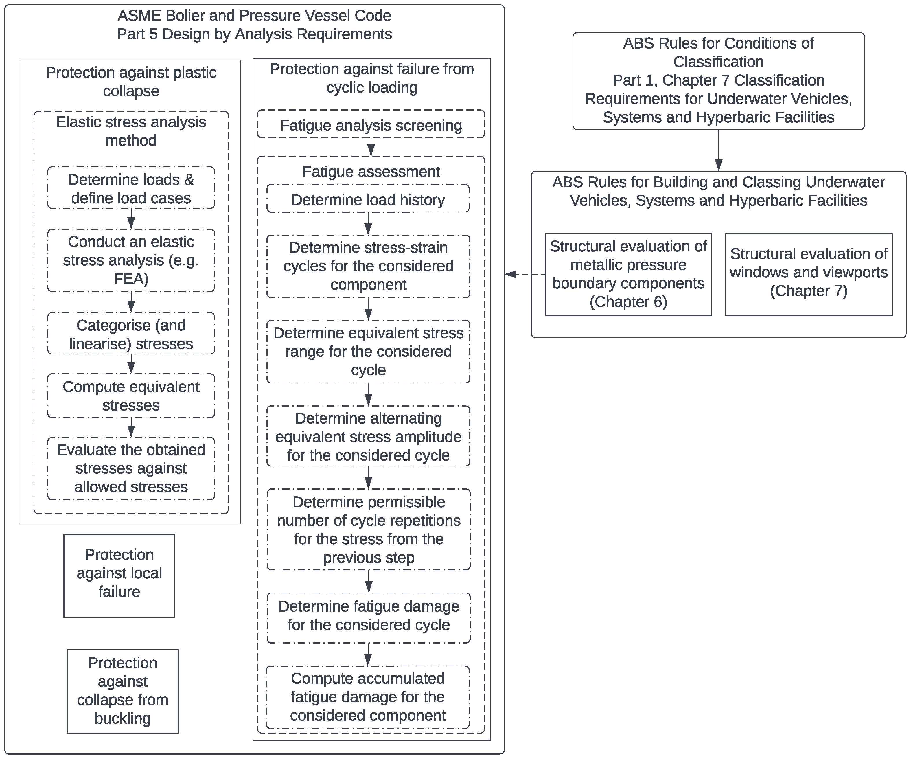
To leverage the benefits of the direct strength analysis, an approach by the American Society of Mechanical Engineers (ASME), called the design-by-analysis (DBA), is investigated in this paper. The methodology is a part of ASME’s Boiler and Pressure Vessel Code (BPVC) [
12].
The code that first appeared in the 1960s was intended for nuclear facilities. Subsequently, new parts have been added facilitating its application in a broad range of structures that need to withstand a pressure gradient directed inwards (external pressure) or outwards (internal pressure). The pressure hull of the submersible will, in this regard, be considered as a pressure vessel under the external pressure and application of the ASME’s code on the metallic part of the structure will be investigated in the following sections.
There are two ways of demonstrating that a pressure vessel fulfils the BPVC criteria [
12]. The first one is the design-by-formula (DBF) approach, which shares all the pros and cons of the approach based entirely on classification societies’ rules [
13]. The other approach called design-by-analysis (DBA), undertaken here, is based on direct strength analysis by means of FEM and can potentially result in lighter and safer structures, which has been demonstrated in many studies that deal with shore-based pressure vessels.
In their analysis of a vertical pressure vessel with skirt support, Diamantoudis and Kermanidis demonstrated [
14] that the maximum allowable pressure on the structure is as much as 40% higher for mild steel and 70% for a high-strength steel when the DBA approach is used instead of the DBF approach. An even greater difference is reported in [
15] where the allowable pressure is 2.32 times greater when the DBA approach is used for the mild steel and 2.5 times greater when the DBA approach is used for the high-strength steel compared with the results obtained by means of the DBF. The main differences between the two studies are that the elastic-plastic method of [
12] is used in [
14], while the limit state method is used in [
15] and the results are compared at different positions, which might explain the discrepancy.
Similar conclusions can be derived from studies concerned with marine structures. In [
16], the structural behaviour of high-strength steel hemispheres is determined by means of physical experiments and numerical models. The obtained critical collapse pressures are then compared with the pressures determined according to the rules of classification societies, including the Underwater Vehicles Rules of ABS [
8]. The pressures determined based on FEA differ up to 8% from the experimental results, while the critical pressures obtained by means of ABS’s rules are between 28% and 36% greater than the experimental results, which implies the margin available for potential savings when the direct strength assessment methods are used.
An analogous study [
17] on ring-stiffened steel cylinders, conducted by the same research group, showed that the collapse pressure determined based on FEA differ from the experiments by up to 14%, while the ABS rules give a conservative collapse pressure assessment of as much as 29%.
An interesting study of Pranesh et al. [
18] is concerned with structural design and analysis of a spherical steel submersible for three persons. The authors calculate the collapse external pressure for the submersible of an internal diameter of 2100 mm and shell thickness of 25 mm. The pressure is 8.54 MPa and 11.47 MPa obtained according to the ABS’s rules and nonlinear FEM, respectively, for the same safety factor of 1.5. The potential material and weight gain can be seen more directly in the part of the study where the pressure is held constant while the required shell thickness is calculated. The required shell thickness for the collapse pressure of 7.5 MPa and the stated factor of safety is 22.15 mm according to the ABS’s rules and 17 mm according to the nonlinear FEA.
Two recent studies have used ASME’s BPVC in submarine/submersible design. Ma et al. [
19] used the DBF approach of ASME’s BPVC in the design of an innovative subsea shuttle tanker concept. The tanker, similar to the Seabus concept dealt with here, has metallic fore and aft peaks while the central portion of the hull is flooded when the tanker is submerged. The central portion comprises cargo, compensation, and other tanks that are designed according to the DBF approach. The peaks are designed according to the DNV’s naval code.
In the study of Sohn et al. [
20], ASME’s BPVC for composites is used in assessing the collapse pressure of a submarine hull made of composite materials. The results were then compared with FEA results and the design-based collapse pressure was significantly lower for all test configurations than the pressure determined based on the direct strength calculations.
Within the context of the rationally based design, the DBA of a pressure vessel can be paired with a structural optimization tool leading to significant savings in terms of structural weight and the material used. In [
21], a steel internal pressure vessel is optimized by connecting ANSYS, structural analysis software, with an optimizer in Matlab. The structural analysis is based on linear elastic FEM where the optimization problem is defined as follows. Thicknesses of the pressure vessel shell are defined as design variables that are varied to minimize structural weight while the optimization constraints are based on the ASME BPVC requirements for DBA following the same procedure that will be demonstrated in this paper. It is demonstrated that the final structure has the structural weight reduced by almost 40%.
The paper is structured as follows. After the Introduction,
Section 2 elaborates on the proposed procedure and shows its departure from the rulebook approach of ABS and presents relevant characteristics of a tourist submersible concept with emphasis on the pretension force.
Section 3 demonstrates the workings of the procedure on structural analysis of the submersible. For the sake of completeness,
Section 4 provides a brief discussion on the main aspects of non-metallic parts of the pressure hull, which are not dealt with in detail in this research. The paper ends with relevant conclusions.
DBA has been used so far in the structural design of unconventional offshore pressure vessels, while in the present paper it is used for the first time for dimensioning of structural components of the underwater vehicle. The main issue in the structural design of innovative structures is to find the right balance between applied design loads, finite element mesh size, and safety factors for different failure modes, which is consistently proposed within the DBA approach. This study may therefore be used as a guidance and incentive for future application of DBA in the development of innovative structures predominantly exposed to pressure loading.
3. FEM Structural Analysis
The elastic stress analysis is performed by employing the FEM approach with 2D shell elements. The analysed submersible was designed based on ASTM 516 Gr65 steel which, according to the ASME in
Section 2, Part D, has the maximum allowable stress of 161 MPa. Furthermore, a high tensile steel (ASTM 841 B) is used for lifting lugs which are modelled by 3D solid elements to account for high stresses which occur due to emergency lifting conditions. Therefore, for the components which are modelled by shell elements and mild steel, two allowable primary membrane stresses, depending on their location, have been conservatively established at
S = 150 MPa and
SPL = 1.5
S = 225 MPa. As described in
Section 2.1, membrane stresses are relevant in most parts of the structure while local primary membrane stresses are evaluated in the vicinity of the structural discontinuities. Steel parts are modelled using shell elements with mesh size
t ×
t (
t is the thickness of the structural element), while longitudinal rods are modelled by circular bar elements.
As the employed analysis is predominantly linear and the mesh convergence study is not a mandatory requirement in DBA, this was not performed within the scope of the present analysis. Furthermore, it is known that the stress concentration is decreasing for coarser mesh size and that the accuracy of the geometry modelling is reducing. The applied plate elements with mesh size
t ×
t are well known in the maritime industry, and it is considered as the standard for fatigue analysis of thin-walled structures [
31]. Such very fine mesh encompasses all geometry stress concentrations and finer mesh than
t ×
t is not recommended in the offshore engineering practice. An alternative to such very fine mesh of plate elements is to use solid elements with at least three elements across the plate thickness. As the plate thickness is generally relatively small (about 20 mm), such a solid element mesh is considered as rather impractical for modelling the whole submarine structure. Nevertheless, in the present study solid elements are used in model areas where credible stress distribution cannot be obtained by shell elements, such as for the lifting lugs for the considered lifting conditions.
FEM analysis is performed for individual components and hull assembly for different load cases. This is necessary to determine possible stress increase due to interactions between individual components. In most cases, loads correspond to the test depth pressure of 65 m except for fatigue assessment which is analysed for the design depth of 50 m. Boundary conditions are employed to have minimal impact on the results while restraining rigid body motion. Preliminary results of the structural analysis and some complementary considerations in addition to those given in the following subsections may be found in the conference paper [
28].
3.1. FEM Analysis of Submersible Structural Components
Individual components of transverse rings, fore and aft end cupolas, as well as battery cylinders are analysed as separate models. As previously emphasized, all employed boundary conditions are applied in such a way that they have minimal impact on the results while restraining the component rigid body motion.
Thus, the FE model of the ring is restrained in
x-direction at supports of the longitudinal rods since that location is bolted to the exo-structure. Furthermore, four additional springs are used in the mid-span of the flanges to restrain the rigid body motion of the ring for the buckling analysis. Springs in the vertical, centreline plane have negligible stiffness in the
y axis, while the same negligible stiffness is considered in the horizontal symmetrical plane in the z direction. For the component analysis of the fore and aft cupola, fixed boundary conditions are applied on the upper and lower fins since these components are bolted to the exo-structure at those locations. Finally, for the analysis of the battery cylinder, the translations in all three axes as well as rotation about the
x-axis are restrained at the fore cylinder end, while transverse and vertical motions together with
x-axis rotation are restrained at the aft cylinder end [
32].
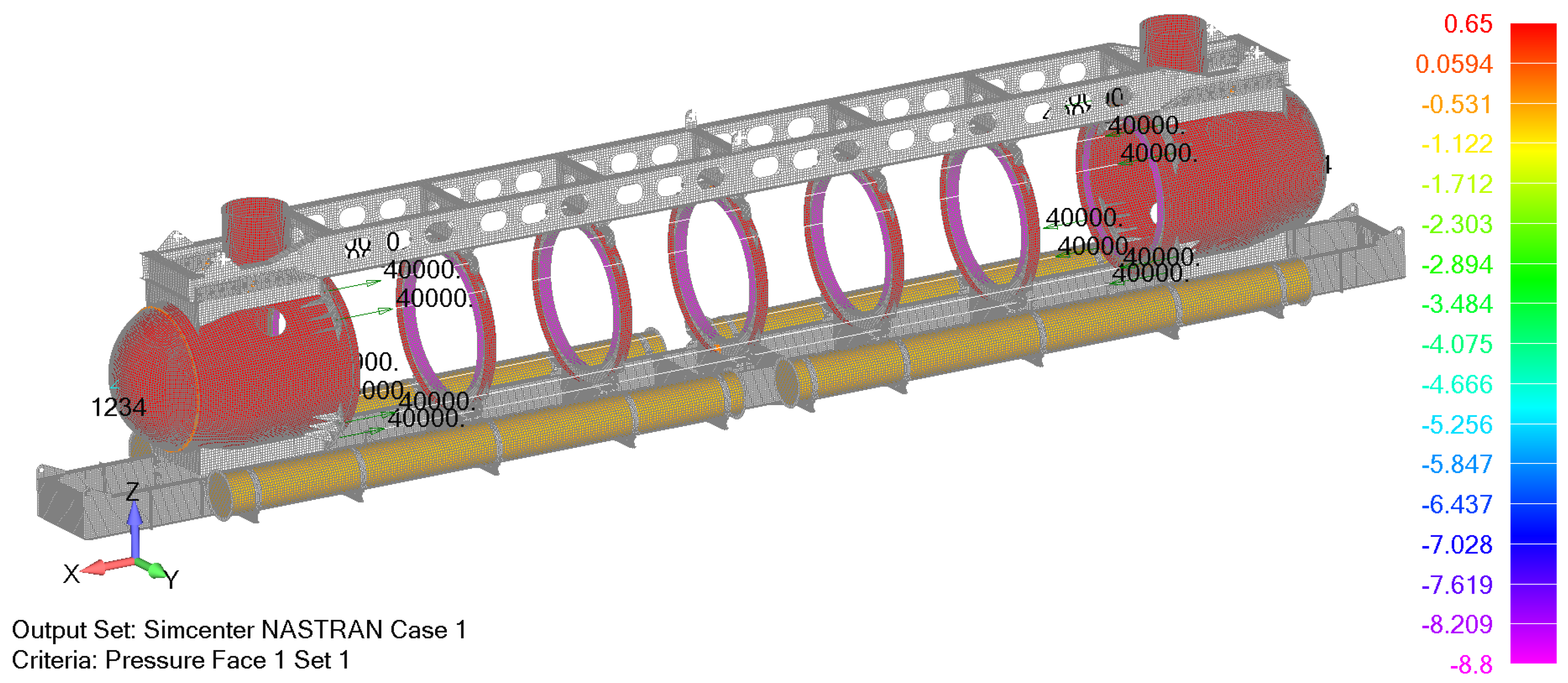
Yielding and buckling analyses are performed for the test depth of 65 m. Thus, the cylindrical battery pod is loaded with the external sea pressure of 6.5 bar (0.65 MPa) on the outside housing. In the case of transverse rings and aft and fore cupolas, an additional pressure of 8.8 MPa, which is the equivalent load, transferred from the acrylic surface of the half cylindrical section is considered. It is conservatively assumed that the whole pressure from the acrylic cylinders is transferred to the inner flange of the analysed component as presented in
Figure 4.
For the analysis of steel heads, the preload is modelled by longitudinal forces of 40 kN per bar as calculated in the previous section and the corresponding pressure of 0.277 MPa in the opposite direction on the part of the head. Thus, the equilibrium of forces acting on the head is ensured. The results of the analysed components which satisfy previously described criteria are summarized in
Table 3 while
Figure 5 shows buckling results for the cylinder batter pod.
3.2. FEM Analysis of Submersible Assembly
For the structural assembly of the submersible, the yielding failure is determined for two load cases, i.e., submerged and lifting conditions while the buckling load factor is calculated for the submerged condition only. Radial and angular deformation analysis is performed for the test submerged condition according to the safety standard for pressure vessels for human occupancy—PVHO-1 [
27]. Finally, fatigue analysis is evaluated for the design case of the submerged condition, i.e., 50 m.
The connection between the steel hull and the exo-structure is achieved by bolts which are modelled by beam elements. Nine bolts are used for the connection between one fin and the supporting structure while four bolts connect one lug of the web ring with the exo-structure.
3.2.1. Yielding Analysis
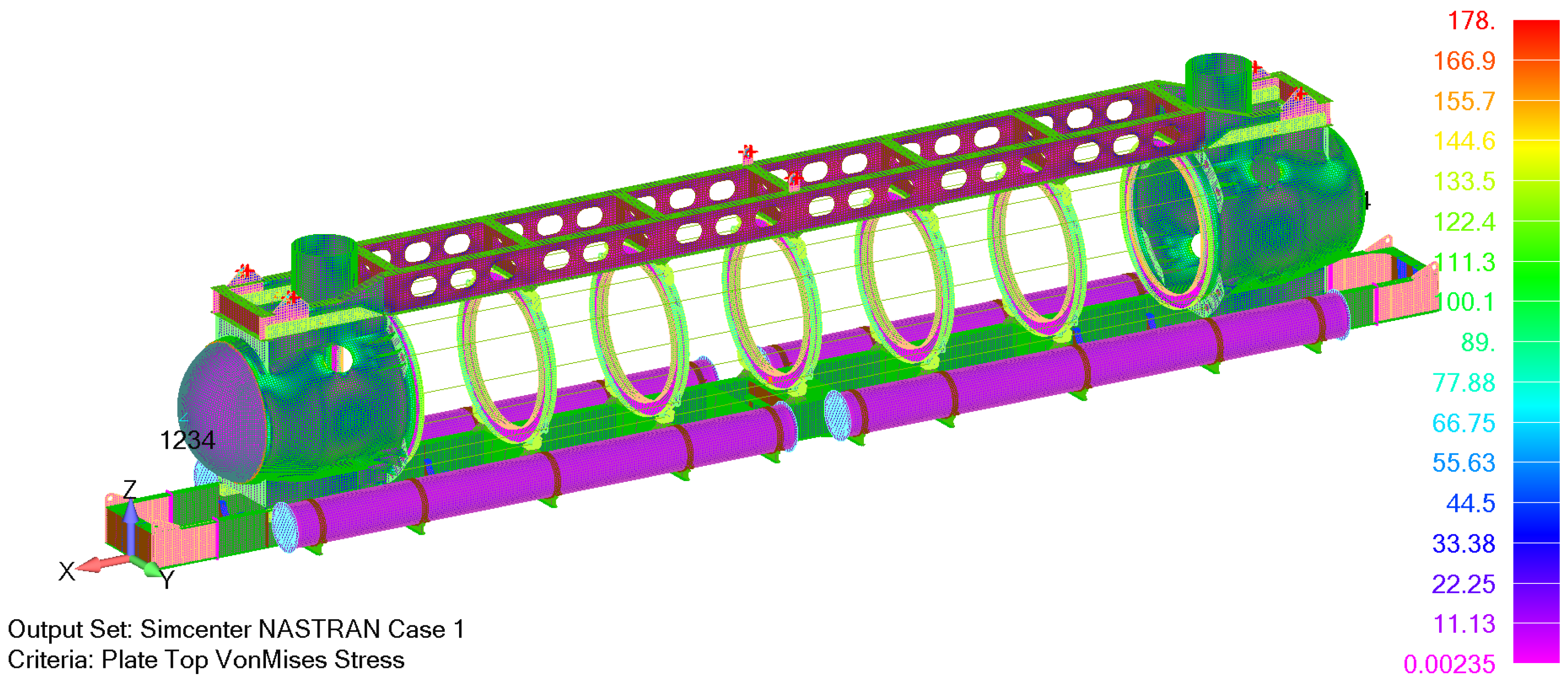
Pressure loads and preloads for the structural assembly are applied in an analogous way for the transverse rings and steel heads. As previously described, transverse rings are loaded with the external sea pressure of 6.5 bar (0.65 MPa) on the outside, exposed flange, while the inner flange is loaded with 8.8 MPa. In the case of aft and fore heads, the hydrostatic pressure load of 0.65 MPa is combined with the pressure due to preload (0.277 MPa) that acts on the web of the first ring and corresponding forces of 40 kN which acts on the longitudinal rods. The external pressure of 0.65 MPa also acts on the cylindrical battery housing as presented in
Figure 6.
Boundary conditions for the global analysis of the whole submarine are applied on the tip of the fore and aft heads. All three motions and rotation of the
x-axis are restrained at the fore end, while the transverse and vertical motions as well as the
x-axis rotation are restrained at the aft head. Loads and boundary conditions are presented in
Figure 6.
The results of the yielding analysis are similar to the component analysis results. The majority of structural elements satisfy the design requirement of maximum membrane von Mises stress of 150 MPa, while only local exceedance in the flanges of transverse rings connected to the heads are noticed. The maximum local primary von Mises stress of 178 MPa is well below permissible local value of 225 MPa. The resulting von Mises membrane stresses from the analysis of the structural assembly are presented in
Figure 7.
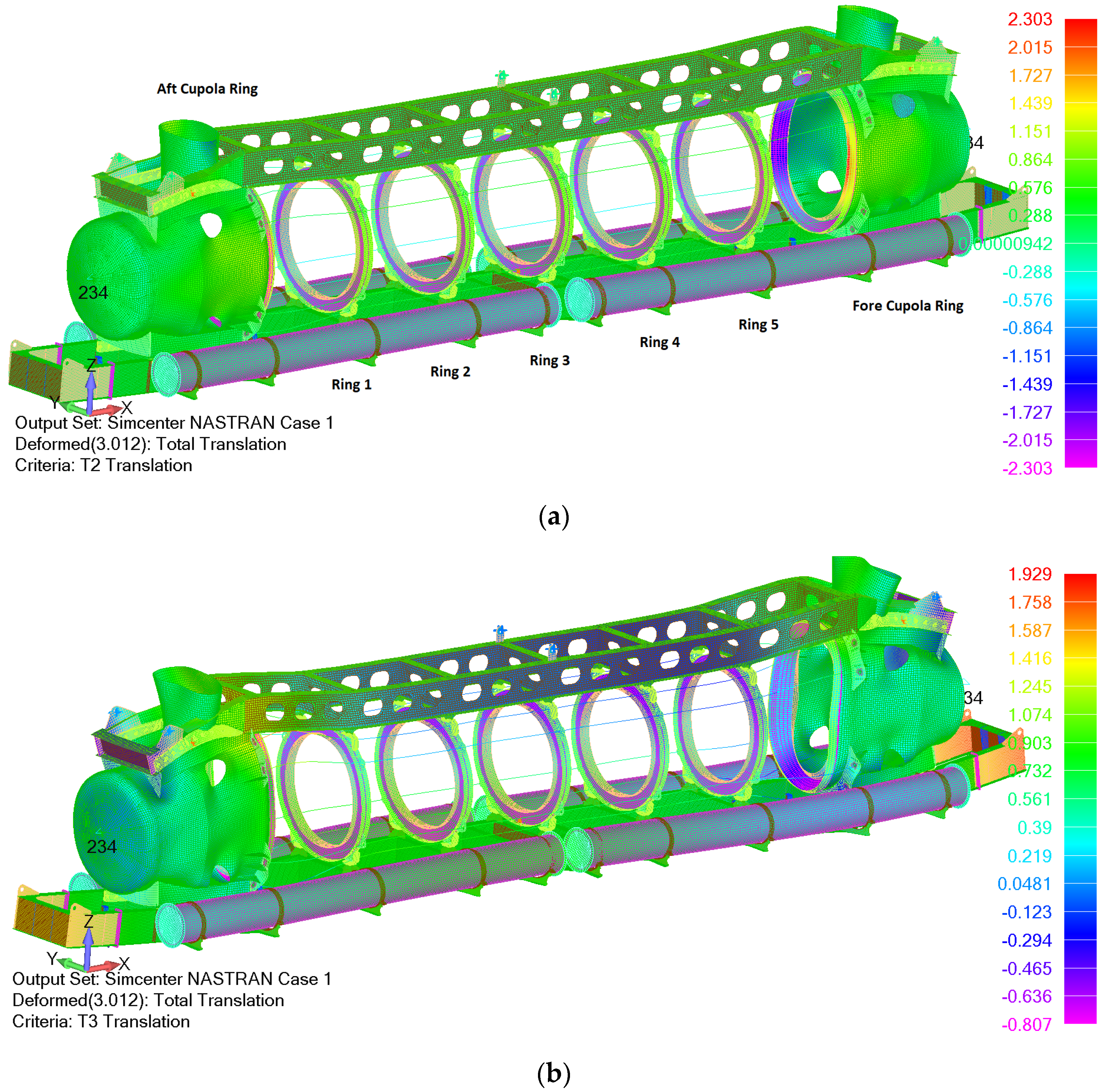
3.2.2. Radial and Angular Deformation Analysis
Radial and angular deformation analysis is performed for large openings according to safety standards for pressure vessels for human occupancy [
27]. Based on the PVHO-1 requirements for large openings, a maximum radial deformation
rmax of the window seat at maximum internal or external pressure must be less than 0.002·
Di, where
Di in our case reads:
In the case of angular deformation, the maximum allowable deformation should be less than 0.5°. Radial deformation can be calculated based on deformations in
y and
z directions, which are presented in
Figure 8. The results are extracted for nodes with maximum translation on the inner flange diameter of each ring. The first node represents the location with the maximum translation on the connection between the web and flange, while Node 2 represents the corresponding node on the edge of the flange (100 mm from Node 1). Based on these deformation analysis results, it can be concluded that all maximum radial deformations on each window are less than the PHVO-1 requirements. The maximum radial deformation is obtained for the central ring as expected while the maximum angular deformations are calculated for the connection with the aft and fore cupola. All deformation requirements are satisfied.
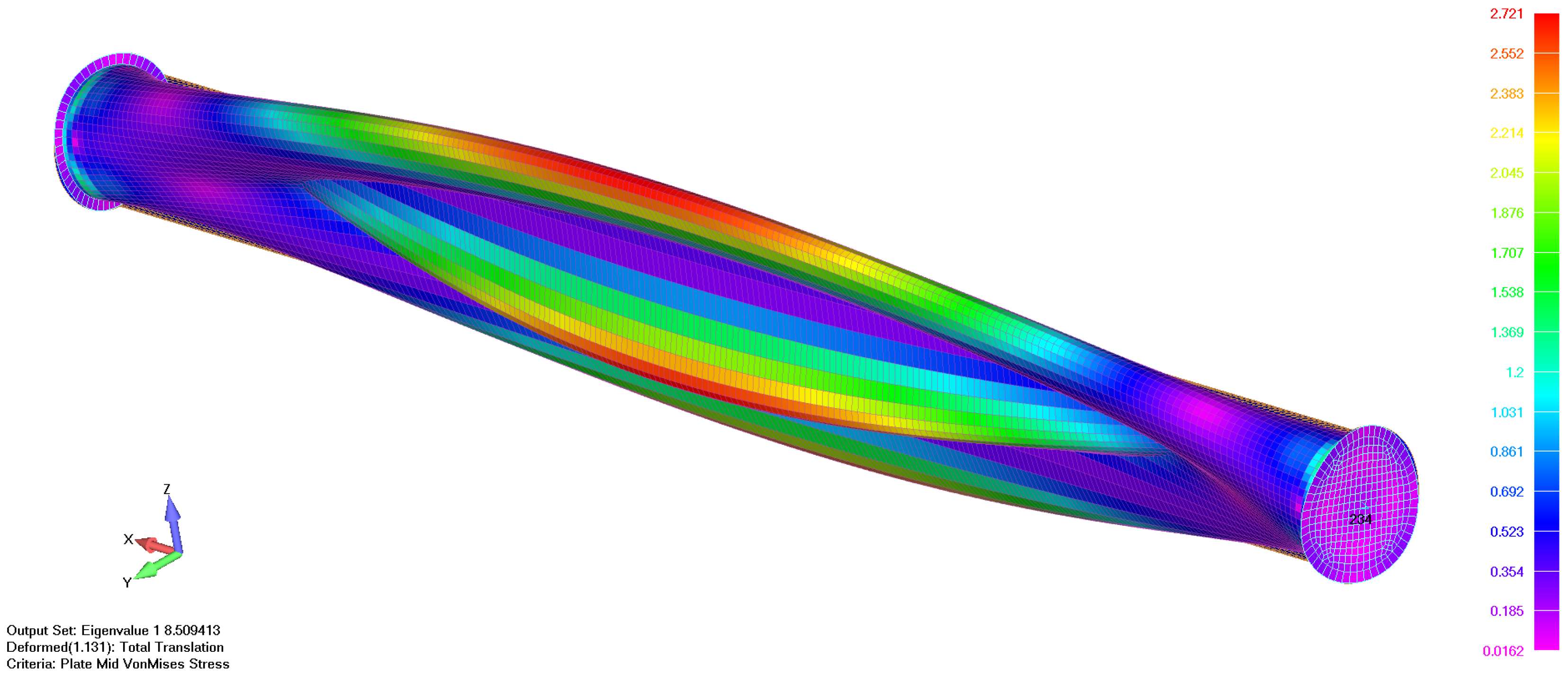
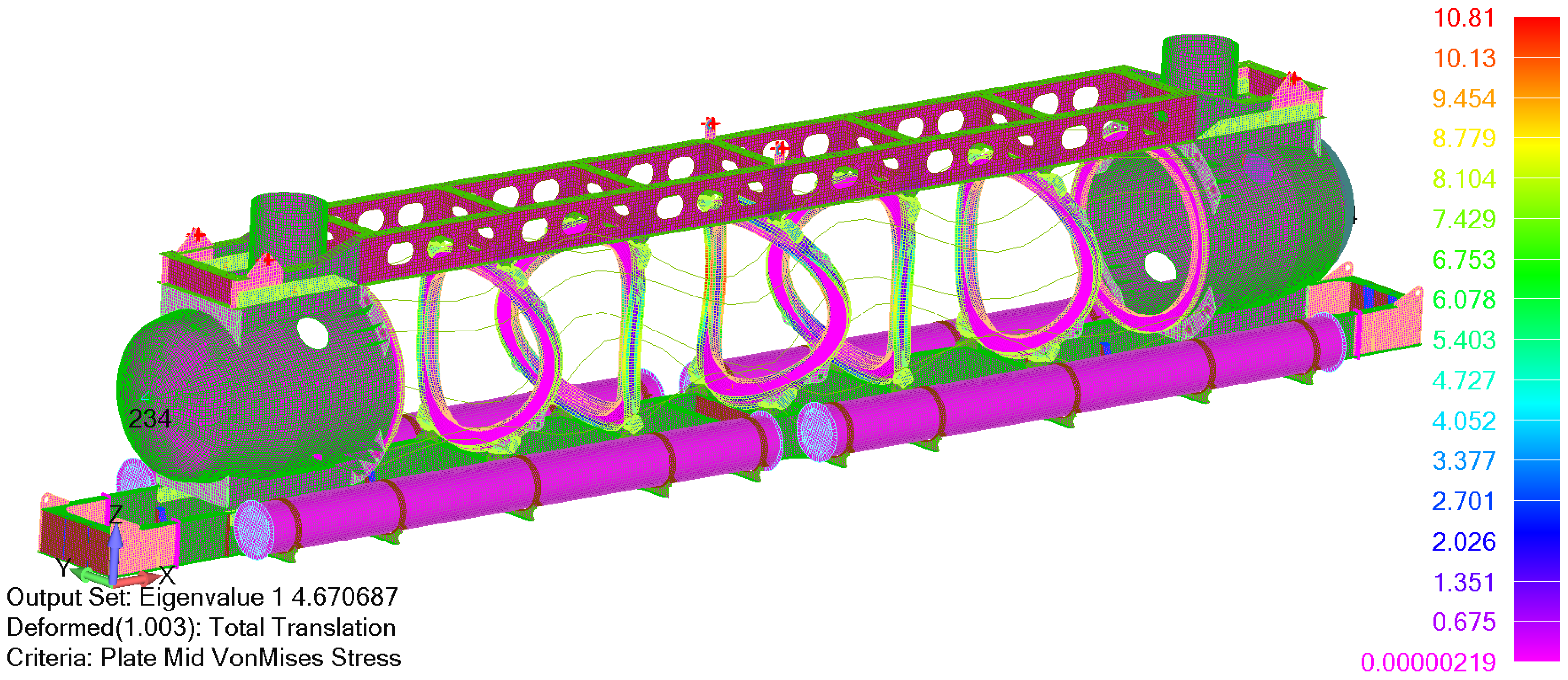
3.2.3. Buckling Analysis
The lowest global buckling failure mode of the assembled structure is shown in
Figure 9, where an adequate buckling load factor of 4.67 is achieved.
3.2.4. Fatigue Analysis
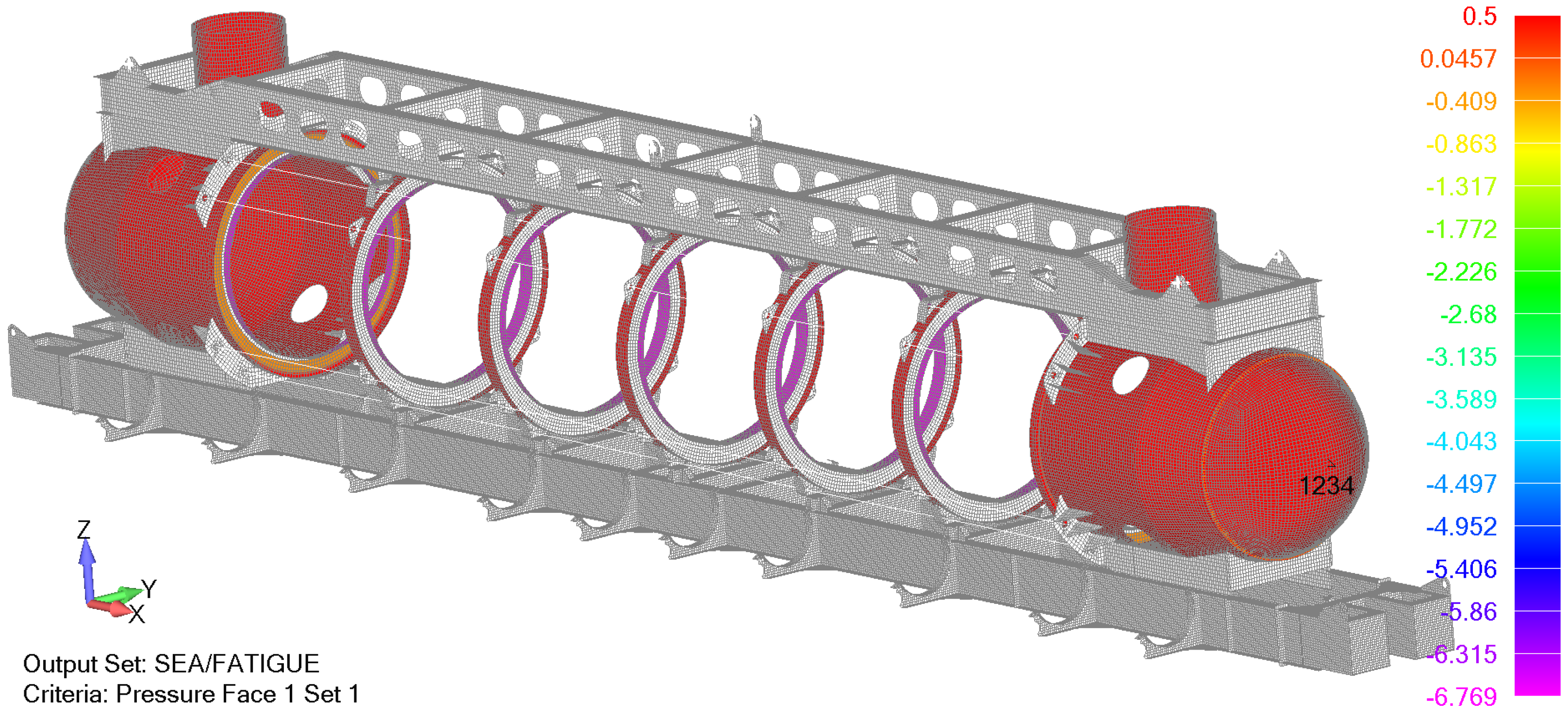
Fatigue analysis is performed for the design depth of 50 m where transverse rings are loaded with the external sea pressure of 5.0 bar (0.5 MPa) on the outside, exposed flange, while the inner flange is loaded with a pressure of 6.8 MPa, which is transferred from acrylic cylinders. Additionally, in the case of the aft and fore heads, the hydrostatic pressure load of 0.5 MPa is combined with the pressure due to the preload (0.277 MPa) that acts on the web of the first/last ring as presented in
Figure 10. The same boundary conditions are assumed for the yielding analysis at the test depth.
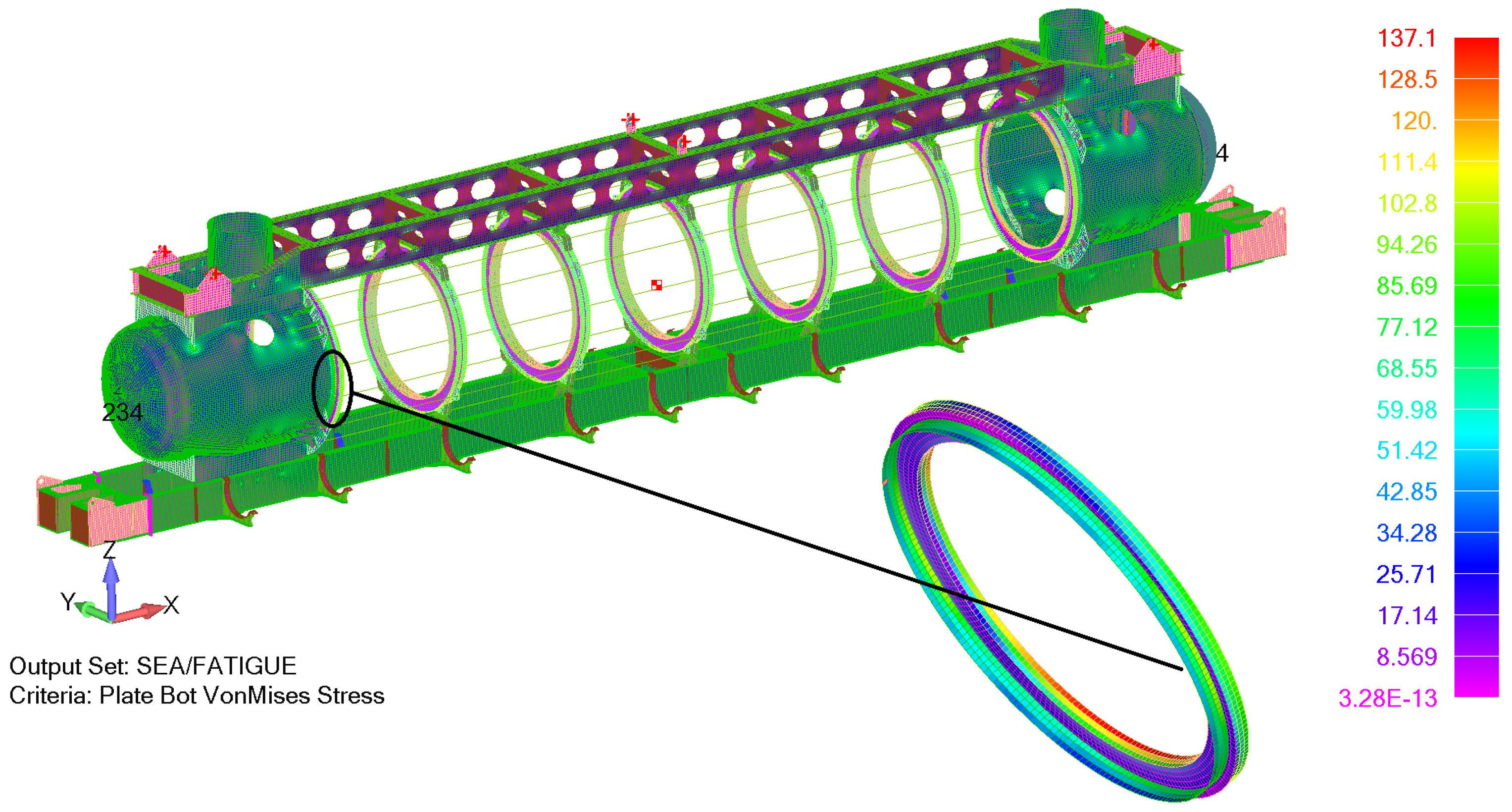
As the yielding analysis revealed potential stress concentration locations, the fatigue analysis is performed for those details as presented in
Figure 11. Two details are analysed:
The fatigue analysis is performed based on effective equivalent stress ranges considering fatigue strength reduction and fatigue penalty factor. The equivalent stress ranges are calculated based on plate bottom stress components since higher values of von Mises stress were obtained for the bottom plate compared with the top plate. The extracted plate bottom components are extrapolated by the hot spot stress approach and from extrapolated components the effective equivalent stress ranges are calculated as 57.7 MPa.
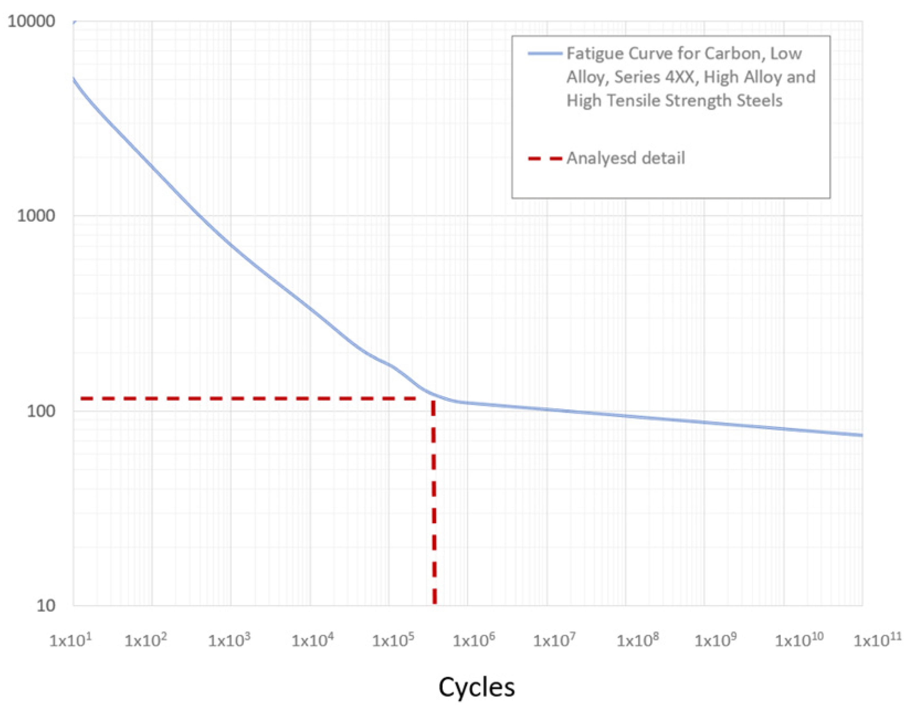
Based on the calculated effective equivalent stress ranges and effective alternating equivalent stress amplitude, the permissible cycle life based on the ASME fatigue curve of the adequate material can be determined. From
Figure 12 it can be concluded that the permissible number of cycle repetitions is slightly below 2.2 × 10
5. Since the number of cycle repetitions is 25,000, the fatigue assessment criterion (accumulated fatigue damage) according to (7) reads:
Therefore, the design of both details is safe.
3.2.5. Lifting Analysis
Following the preliminary calculations, the design with eight lugs is proposed to meet the requirements of lifting conditions. Generally, lifting conditions are analysed to ensure that:
First, a normal (static) lifting condition is analysed where a nonlinear analysis is employed since the nonlinear gap elements simulate contact between lifting cables and lifting lugs. During the iterative procedure of nonlinear analysis, the gap elements employ a large (almost infinite) stiffness in the compression condition and zero stiffness in tension. This ensures that the pulling force of the lifting cables is distributed on the nodes in the lifting ears.
Loads are simulated by a submersible weight that reads
W = 156.4 t and a gravity constant g = 9.81 m/s2. The model is restrained in the transverse direction on the tip of the aft head and in longitudinal and transversal direction on the tip of the forehead as presented in
Figure 13. Moreover, the vertical motion is restrained in the centre of the lifting ears to simulate the tension of lifting cables.
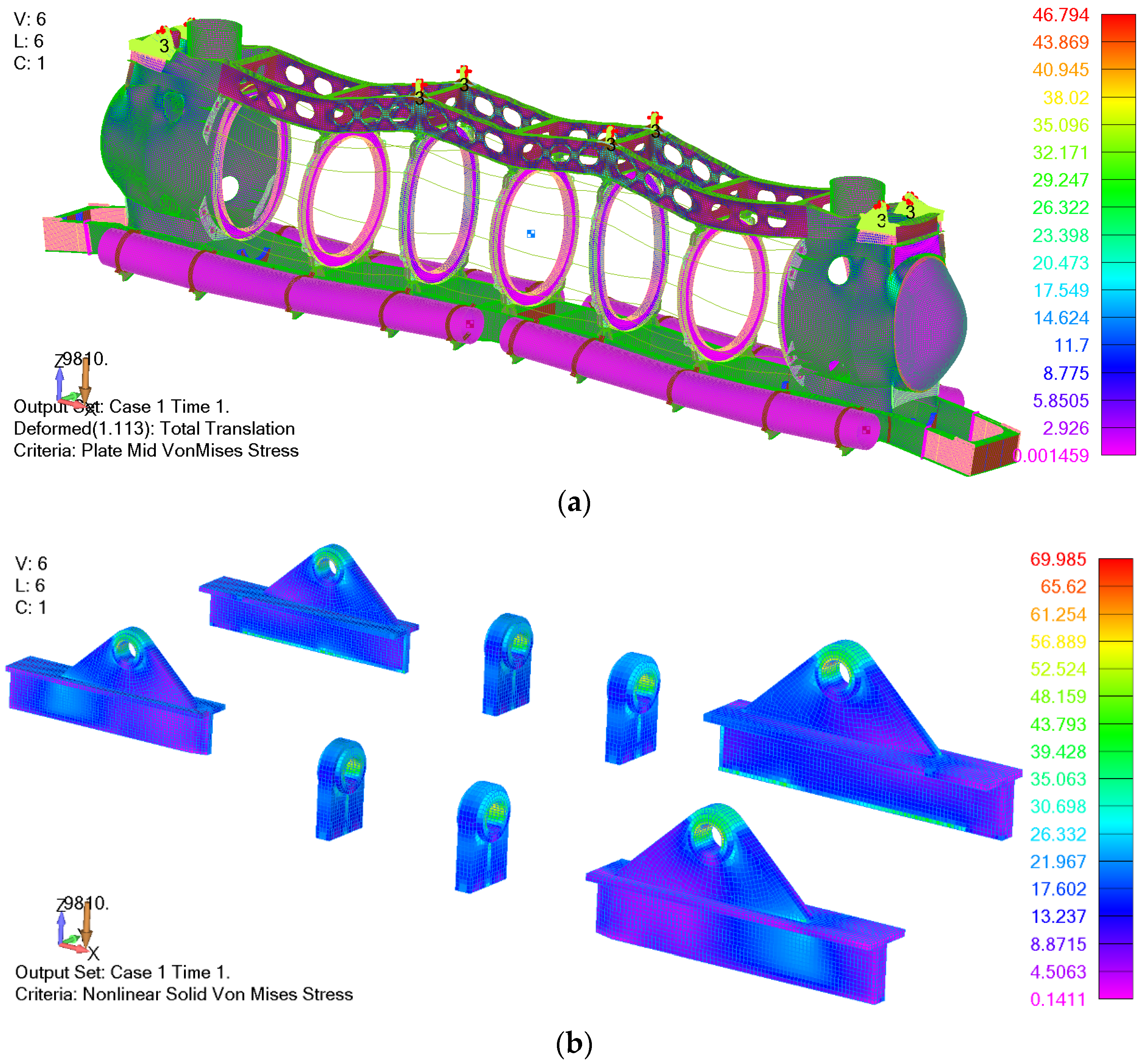
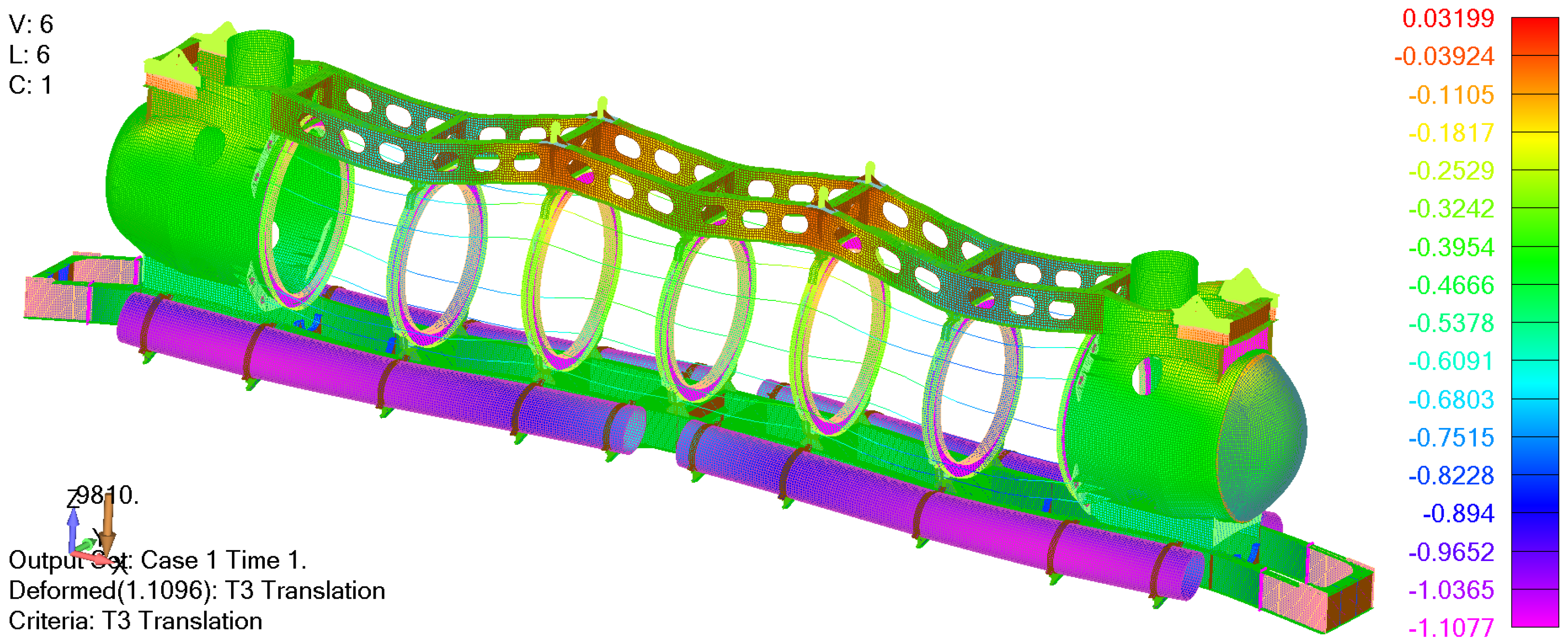
The results are presented in the following figures where
Figure 14 shows the deformed model with von Mises stresses. It can be observed that maximum stresses of 46.8 MPa in shell elements and 69.9 MPa in solid elements are well below permissible values. Furthermore, displacements during lifting of the vessel can be seen in
Figure 15. The maximum vertical displacement can be determined as 1.1 mm while relative displacements at the ends of the first cylindrical sections (between the first and second ring) are calculated to be 0.8 mm, which is found to be satisfactory by the criteria for acrylic windows. Namely, such a reasonable level of the relative displacements should assure that acrylic cylinders will not be damaged during frequent lifting operations with the submersible.
Besides lifting in the normal condition during launching, it is necessary to evaluate two additional lifting conditions according to ABS, which can be found in Section 6 of
Underwater Rules [
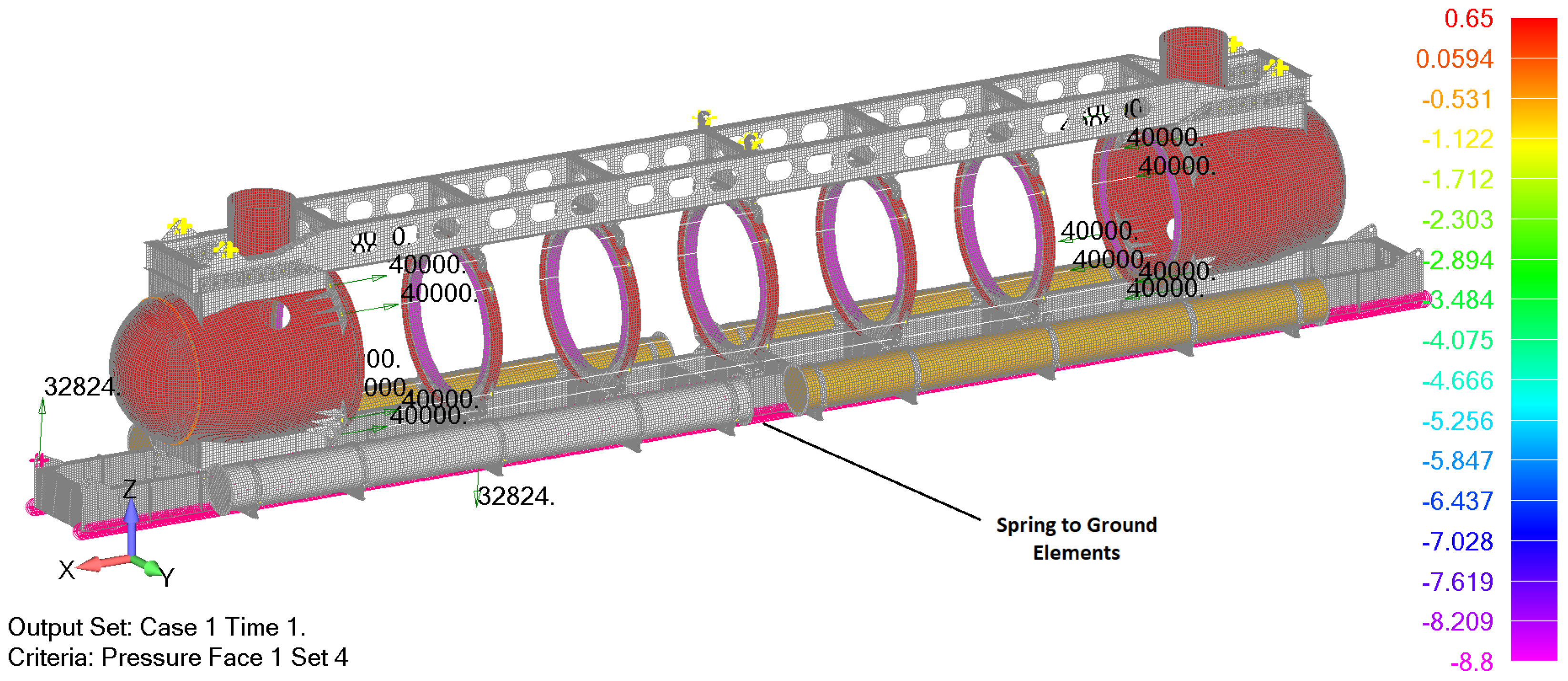
8]. The first one is the lifting condition from the seabed in the case when one of the battery pods is damaged.
The mass of the flooded battery housing reads 3346 kg which corresponds to the force of 32.8 kN. Since it is assumed that the forward battery pod on the port side is damaged, the upper and lower lifting lugs in the fore part of the submersible are analysed. In the first case, the lifting force due to the damaged battery pod acts on the upper, port side lug, while in the second case, the same force acts on the lower, starboard lifting lug. In both cases, the external pressure of 0.65 MPa on the test depth is considered as well. Boundary conditions for this lifting condition are simulated using spring to ground elements with very low stiffness of 1 N/mm to prevent rigid body motion. The loads when lifting force acts on the lower starboard lug are presented in
Figure 16.
Results from the nonlinear analysis are presented in
Figure 17 where mid-plate von Mises stresses are shown when the lifting force acts on the lower starboard lug. The maximum stress of 174 MPa is in same range and below permissible values as the one obtained in the global strength analysis for the test depth presented in
Figure 7. Moreover, von Mises stresses around the loaded lifting lug are well below permissible values. Comparable results are obtained in the case when the lifting force acts on the upper portside lug as well.
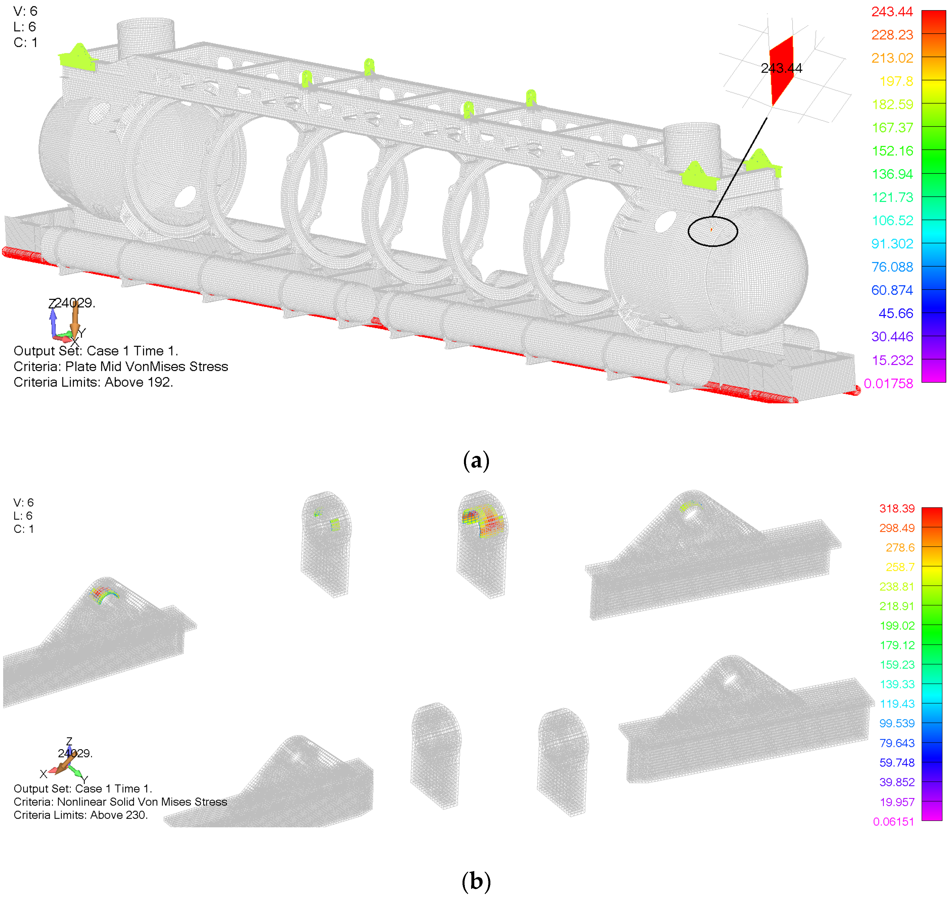
The third analysed lifting condition is the launching/recovering condition at rough seas where the primary lifting lugs and lifting attachments must be analysed for forces of at least 2 g vertical (1 g static plus 1 g dynamic), 1 g transverse, and 1 g longitudinal, acting simultaneously under the most severe loading condition [
8]. Thus, the resultant acceleration for the emergency lifting condition reads 25.03 m/s
2.
The results from the nonlinear analysis are presented in
Figure 18 and
Figure 19 where a deformed model with von Mises stresses is shown. The maximum mid-plate von Mises stress of 243 MPa is recorded as may be seen in
Figure 18a. Based on these results, designers reinforced the critical areas with high-tensile steel with permissible values of 332 MPa (80% of yield strength).
Figure 18b shows von Mises stresses for lifting lugs, which are modelled by solid elements and high-tensile steel. Based on the ABS Rules [
8] for the allowable stress of contact problem, 100% of the yield strength of the material (415 MPa) can be used as the limit value. Thus, according to the results in
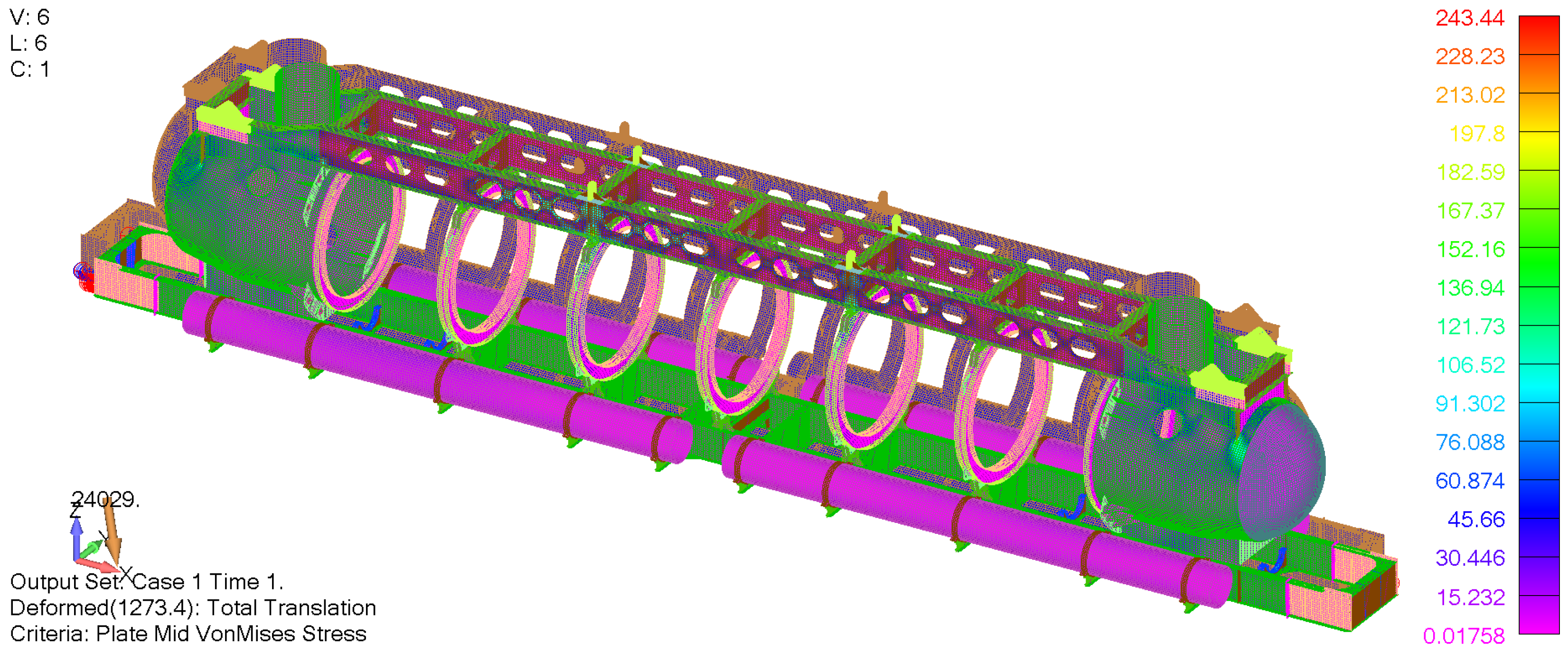
Figure 18b, all solid elements satisfy the given criteria. Furthermore, the total translation can be seen in
Figure 19, where it can be concluded that the model rotates around the
x axis.
4. Discussion about Non-Metallic Parts of the Pressure Hull
There are two major non-metallic structural groups: the acrylic cylinders and parts of the exo-structure such as soft ballast tanks. The latter parts are not subjected to differential pressures and thus are not required to be included in the pressure hull design. Acrylic cylinders, however, are designed as per the PVHO-1 design standard which does not allow for direct structural assessment of windows [
27]. As the stiffness of the acrylic material is almost negligible compared with the steel, the influence of the acrylic cylinders on the structural strength of the pressure hull is rather small. For that reason, acrylic cylinders can be omitted from the analysis of the steel pressure hull without affecting the accuracy of the analysis. Since this paper deals with the analysis of metallic parts of the submersible’s structure, only basic aspects of design and analysis of polymeric parts will be given here. Due to the importance of acrylic cylinders, these aspects must be considered even when the designer is concerned only with the metallic part of the structure and it can be assessed by means of simple formulae and diagrams, at least as a preliminary assessment.
Acrylic cylindrical hull sections are fitted between supporting rings (
Figure 2). Due to the structural arrangement where the exo-structure with the fore and aft ends takes most of the loads, the acrylic cylinders are loaded only locally, i.e., external hydrostatic pressure that acts on them is transmitted to the steel rings which are rigidly connected with the exo-structure. Thus, the pressure causes the cylinders to bend between the rings. Since the cylinders are not free to expand in the longitudinal direction, this will typically cause axial stress [
2].
The analysis of the problem can be simplified by observing that cylinders, the loads, and the supports are axisymmetric. This means that the problem can be analysed as an axisymmetric problem instead of as a 3D problem. Not only does this facilitate a potential thorough analysis, but it also enables the use of simple analytical formulae that can be found in many engineering handbooks [
33].
Besides bending, the cylinders will exhibit significant thermal deformations too. This is a consequence of the thermal properties of acrylic plastic. For example, the coefficient of linear thermal expansion will increase as much as 16% from 4 °C to 27 °C based on data from [
27]. This will lead to a variation in the length of the cylinders of a couple of millimetres. If unaccounted for, significant axial forces will arise, which can lead to fatigue failure [
2].
Fatigue can also arise due to axial force variation [
2]. In the submersible design proposed and analysed in this paper, the exo-structure ideally takes all global loads, which also includes axial force that arises due to hydrostatic pressure that acts on the fore and aft ends of the submarine. Since the ends are fixed to the exo-structure and very stiff, maximum horizontal deformation at the connection with the cylinders is 0.53 mm, which can be obtained from the structural analysis demonstrated in
Section 3.2.1 and adjusted for the operational depth of 50 m. This is very close to the thermal deformation obtained in [
9] and should be accounted for by the deformation of the side gasket. Structural analysis of a joint between the steel ring and the cylinder is a complex problem that will be dealt with in a separate paper.
The third potential failure mode of the acrylic cylinders is buckling [
2]. The cylinders under external pressure are much less susceptible to buckling failure than cylinders under internal pressure [
2]. To assess the critical external pressure that causes buckling, Stachiw proposes a set of diagrams giving the critical pressure as a function of thickness to diameter and length to diameter ratios [
2]. Based on the diagrams, the critical pressure for a cylinder with dimensions specified in
Table 2 is well above the hydrostatic pressure at the design depth.
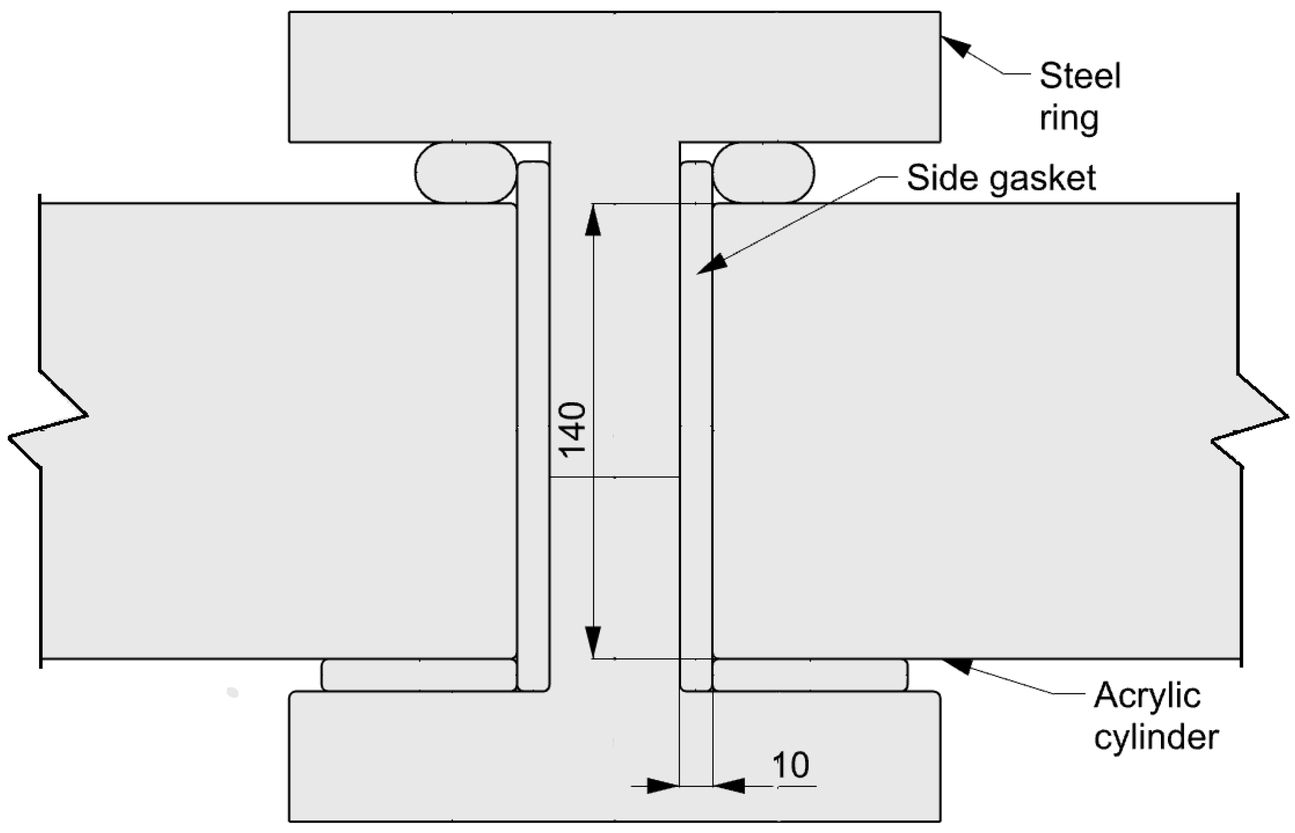
The second non-metallic critical part, i.e., the joint between the cylinders and the steel rings, as shown in
Figure 3, is composed of a seal and three gaskets. Following a joint design proposed in [
2], the seal is made of nitrile butadiene rubber (NBR) and the gaskets are made of chloroprene rubber (CR). Both materials are elastomers, polymeric materials that can undergo large elastic deformations. Their behaviour is hyperelastic and viscoelastic [
28] and can be analysed only by means of numerical methods that can account for large deformations, finite strains, and geometrical and material nonlinearity.
Although the material behaviour is, in general, non-linear elastic, both materials show an almost linear elastic behaviour up to an engineering strain of about 0.2 for CR and about 0.3 for NBR for a strain state relevant in this analysis [
29] with a modulus of elasticity of about 6.5 MPa. This approximation can be used for simple, preliminary assessments of their structural behaviour as demonstrated in a simple calculation of tensile force in the tie rods. Limitations and underlying assumptions of such an analysis are given in
Section 2.2 and should always be observed. Additionally, the seal joint between the cylinders and the steel rings are planned to be experimentally tested to obtain material multi-axial mechanical properties.
5. Conclusions
This paper describes and demonstrates the procedure based on the ASME design-by-analysis approach for the structural design of metallic pressure hull elements of the tourist submersible. Design-by-analysis is a recently introduced approach in structural design practice for pressure vessels, while the application for underwater vehicles described in the present paper is a novelty and main contribution of the study. Based on the proposed approach, a novel touristic submersible, with a capacity of 48 passengers at nominal diving depth of 50 m, was analysed. Furthermore, insight into the analysis of non-metallic parts of the pressure hull as well as preliminary pretension force calculation were given. As the stiffness of the non-metallic parts of the submarine is almost negligible compared with the steel, the influence of the acrylic cylinders on the structural strength of the pressure hull is not considered.
According to the design-by-analysis approach, the pressure vessel component should be evaluated for different failure modes, i.e., plastic collapse, local failure, buckling, and cyclic loading. These failure modes were investigated for the individual components and for the structural assembly as well. Radial and angular deformation analyses were performed for connections of acrylic cylinders according to safety standards for pressure vessels for human occupancy. Finally, important lifting conditions were investigated to optimize the location and size of the lifting lugs. As the lifting analysis revealed the location of high-stress concentration, the lifting ears were reinforced using high-tensile steel. All calculations for operational and design depth were performed using pretension force in tensioned rods that enable safe fastening of the acrylic cylinders with thermal variations and diving depth.
The results of the finite element method revealed that protection against plastic collapse of the pressure hull design is satisfactory, as the primary membrane von Mises stresses were always below 150 MPa, while local membrane stresses satisfy the criteria of 225 MPa. Buckling factors for all relevant metallic structures, i.e., transverse web ring, battery cylinder pod, and fore and aft cupola were above minimum design values. Next, the fatigue life for operational depth and 25,000 cycles was found to be adequate according to the relevant S-N curve where the connection between the aft/fore head and aft/fore cupola ring were analysed as the most dangerous locations for potential fatigue failure. Finally, it was shown that the lifting operations can be performed safely since stresses and deformation for various lifting cases are at satisfactory low levels after reinforcing the lifting ears.
As demonstrated in the study, the design-by-analysis procedure can be recommended for the design of metallic parts of innovative underwater vehicles and other structures exposed predominantly to the pressure loading.


