Review

Shipping Decarbonization: An Overview of the Different Stern Hydrodynamic Energy Saving Devices

by
Flaminia Spinelli
1,
Simone Mancini
2,*,
Luigi Vitiello
1,
Rasul Niazmand Bilandi
3 and
Maria De Carlini
4
1
Department of Industrial Engineering, Università Degli Studi di Napoli “Federico II”, 80125 Napoli, Italy
2
Università Degli Studi “Giustino Fortunato”, 82100 Benevento, Italy
3
Estonian Maritime Academy, Tallinn University of Technology, 11712 Tallinn, Estonia
4
Eurisco Consulting SRL, R&D Company, 80059 Torre del Greco, Italy
*
Author to whom correspondence should be addressed.
J. Mar. Sci. Eng. 2022, 10(5), 574; https://doi.org/10.3390/jmse10050574
Submission received: 1 April 2022 / Revised: 20 April 2022 / Accepted: 21 April 2022 / Published: 23 April 2022
(This article belongs to the Special Issue Energy Saving Devices for Ships)

Abstract

:
In recent years, research into ships has focused on reducing emissions, consuming less energy, and being more efficient. As a result, the maritime industry has been continuing in a green and sustainable direction. Improving the fuel efficiency of ships and the decarbonization of shipping are important issues to reduce fuel consumption and emitted Greenhouse Gas (GHG) amounts. Decarbonization in the shipping industry could be achieved through technical and operational strategies such as Energy Saving Devices (ESDs) to reduce the fuel consumption of new and existing ships. According to the makers, ESDs can optimize fuel efficiency by up to 15%. This paper reviews the current literature on stern hydrodynamic ESDs, which are mainly used on typical merchant vessels, i.e., bulkers, tankers, and carriers. A comprehensive review is carried out analysing the different available solutions for stern hydrodynamic ESDs, the working principles, the methods used for the design, optimization, and evaluation of the performance improvements, and the relevant issues of these specific ESDs.

1. Introduction

The average global temperature has increased by 0.8 degrees Celsius this century, which can be linked to air pollutants and Greenhouse Gases (GHGs) released into the atmosphere. In this regard, the international shipping industry has an important contribution to the production of GHGs, such as carbon dioxide (CO2), methane (CH4) and nitrogen oxide (NOx), black carbon, sulphate particles, etc. According to the International Maritime Organization (IMO) GHG study, international shipping emitted 1000 million tons of CO2 and 816 million tons of other GHGs annually between 2007 and 2012. The maritime industry is receiving increasing attention because it is responsible for 2.2% of Greenhouse Gas emissions, and this share is expected to increase in the future [1]. As it is defined as “hard-to-abate”, because the decarbonization process would require huge investments in terms of money and time, in the Paris agreement of 2015, there was still no context for tightening measures over the maritime industry.
However, the EU Regulation 2015/757 represented a crucial turning point in the approach to environmental issues and climate change in the shipping world. It aimed to reduce GHG emissions to at least 55% below 1990 levels by 2030 and at least 80–95% below 1990 levels by 2050, a significant increase from the previous 40% target [2]. In this context, a Monitoring, Reporting and Verification (MRV) system was introduced in 2017 [3] to collect the emissions data from ships entering and leaving EU ports. These data were collected on more than 11,500 ships and they were verified daily by the EU Commission and the European Maritime Safety Agency (EMSA).
In the same direction in April 2018, the International Maritime Organization (IMO) defined the initial strategy to reduce GHG emissions from shipping by at least 50% by 2050 compared with a 2008 baseline.
Hence, the long-term reduction of emissions implies a growing interest in sustainability. For shipping companies, this means optimizing the fuel consumption of ships. Of course, this issue is not only relevant for the environmental impact, but fuel costs are a major part of the operating costs of ships. Therefore, the development of core technologies to reduce GHG from ships and optimize fuel consumption today is a target of the shipbuilding industry. An interesting and comprehensive overview of decarbonization solutions in the shipping industry was recently carried out by Mallouppas and Yfantis [4].
As shown by the Marginal Abatement Cost (MAC) curves [1], whose function is to illustrate GHG emission reductions from design standards, retrofit technologies, and operational measures that improve ship energy efficiency relative to their costs, optimization water flow reduction potential is claimed above 20% for five major ships (bulk carriers, tankers, general cargo ships, containers) and 10% for passenger ships only.
Regarding new ship-building, since 2013, there has been in force the Energy Efficiency Design Index (EEDI) defined by the Marine Environment Protection Committee (MEPC), an IMO committee, that prescribes a reduction of exhaust GHG for all vessels over 400 gross tonnes (GT) [5]. This is a measure that helps the industry, during the design phase, to decide which technologies should be installed on a specific ship. However, as every vessel is characterized by having a long lifespan (up to thirty years), the replacement of engines will only happen in the long run. As ship-owners are interested in minimizing the downtime of their vessels, fitting highly efficient propellers and rudders and/or equipping them with stationary flow-directing devices, generally called Energy Saving Devices (ESDs), can represent one of the most cost-effective solutions to meet the regulations and improve the ship efficiency.
These regulations do not apply only to new ship-building; recently (June 2021), there has been issued by MEPC the new ship energy efficiency index, i.e., Energy Efficiency Existing Ships Index (EEXI) [6], which covers all the existing vessels above 400 GT. In more detail, ships whose current attained EEXI does not comply with the reference value shall undergo any measure to improve their efficiency. On average, bulk carriers, tankers and container ships notably operate between 11 knots and 14 knots, or between 38% to 50% of their Maximum Continuous Rating (MCR). This is well below the engine loads that would be allowable under the EEXI, which range from 65% to 77% MCR [7]. In this operative rating, the Specific Fuel Consumption of Diesel Engine is far from its optimum; as a consequence, the fuel consumption and emission are very high.
To efficiently reduce ship speed or CO2, thus giving a heavy impact, the EEXI should be able to codify current operational efficiency gains due to slow steaming, rather than further reducing ship speed [8]. Introducing an EPL (Engine Power Limitation) can easily limit the maximum engine power to an optimal range, without any invasive intervention. Another option to comply with the EEXI requirement is to apply ESD, obtaining an increase in the reference speed (Vref) at the same power level, where Vref is the reference speed estimated at reference engine power (generally 75% of MCR) and a certain draught of the vessel (scantling draught) [6]. The advantages of the implementation of ESD on the attained EEXI value are mainly related to the compliance of the IMO rules without applying EPL or even reducing the EPL applied on the main engine with undebatable commercial advantages for the “charter-ability” of the vessels.
In general, with the expression ESDs, a broad spectrum of devices can be included, but the purpose of the present analysis is to investigate the typical hydrodynamic ESDs applied on commercial vessels. These ESDs are mainly focused on reducing the amount of propeller energy losses in the water flow i.e., rotational, or axial losses. The consequence is an equal amount of thrust for the lower engine power, thus yielding lower fuel consumption, and consequently lowering the carbon dioxide emissions. Various types of ESDs have been developed since the energy crisis in the late 1970s and can be applied to existing vessels by means of refitting or can be applied from the early design stages of new vessels.
The ESD, which may also be referred to as stationary flow directing devices, are usually located near the propeller. They vary in position and may be located behind the propeller, on the propeller, or on the rudder. The objective of designing these devices is to improve losses in the ship’s wake and rotational losses in the slipstream. These goals can be achieved by the duct and fins. The history of ESD is explained in more detail in the text.
This article is organized as follows. In Section 2, the background of the problem is presented to explain the targeted ships, propulsive coefficients, and the procedure for selecting the correct ESD. Typical ESD features and installation locations to minimize energy losses are described in Section 3. Section 4 analyses the scale effect on wake. Section 5 analyses CFD’s methods for performing simulations on the ESD application and performance evaluation. The methods and procedures for optimizing ESD are presented in Section 6. Finally, the conclusions are presented in Section 7.

2. Background

2.1. Target Ships

Before going into the details of the review of the energy-saving devices, a brief explanation of the targeted ships is necessary. Notably, the typical commercial vessels (mainly bulkers, oil/chemical/product tankers, and gas carriers) are characterized as full-blocked ships. This feature implies that the flow coming from the bottom of the ship is unable to follow the strong curvature around the bilge, so the fluid elements which were close to the hull tend to leave the near-zone of the boundary layer, and the separated zone is then filled with water flowing from above. The width of the boundary layer is strongly affected by the full blocked hull’s stern, which is rather blunt, and may lead to the onset of separation. The flow leaves the surface proximity due to the adverse pressure gradient and drains energy by adding further resistance. The separation resistance is revealed by a pattern of eddies behind the stern (Figure 1).
Many full-blocked ships belong to the single-screw type, whose inward-directed tangential velocity of the inflow is predominant and can negatively affect the thrust of the working right-hand propeller. By following the same rotation, the wake tangential velocity reduces the propeller rotation rate resulting in a so-called propeller slip loss, lowering its thrust and increasing the inhomogeneity of the accelerated flow behind.

2.2. Propulsive Coefficients

An overview of the different stern hydrodynamic ESD solutions requires a summary of the interactions between the ship propeller and the hull to define the sources of losses and at the same time identify the potential “area” of optimization. Traditionally, the hull required power PD is evaluated as follows:
P D = P E η H · η 0 · η R
where P E is the effective power, η H is the hull efficiency, η 0 is the propeller open water efficiency, and η R is the rotative relative efficiency. The three efficiencies can be combined in one coefficient, called propulsive efficiency ( η D ):
η D = P E P D
Each efficiency shown in Equation (1) represents a key point from the design making perspective, according to which of the three goals must be achieved: enhancement of propeller-hull interaction, enhancement of propulsor efficiency, or overall improvement, as schematized in the below table (Table 1).
The propeller open water efficiency has been extensively investigated in several studies (e.g., Olsen [9]). As highlighted by Terwisga [10], the open water efficiency of a real propeller includes a sum of viscous and rotational losses, besides axial losses, but the latter remains the major part of kinetic energy lost to heat because of the non-uniformity in the wake (Equation (3)).
η 0 = 1 a x i a l   l o s s e s P D   v i s c o u s   l o s s e s P D r o t a t i o n a l   l o s s e s P D
The propeller hull interaction can be defined through the propulsive coefficients. The details about the propulsive coefficients are below depicted.
According to momentum/actuator disk theory, when the propeller is active, it creates a low-pressure field upstream, while increasing the pressure downstream of the propeller. The low-pressure field will depend on the shape of the stern, resulting in additional pressure resistance. Additionally, the acceleration of the flow induced by the propeller increases friction at the stern, which also adds up to the negative force in a longitudinal direction. Therefore, it follows this expression:
R T = T ( 1 t )
where R T is the resistance of the ship in a towed condition, T is the required thrust force in a propelled condition, i.e., the resistance including the suction of the propeller, and t is the thrust deduction factor.
The wake factor w is the difference in ship speed and the axial velocity component; it is commonly known as the “wake fraction”:
w = 1 ( V A V S )
where VA is the axial velocity and VS is the ship speed.
Together with the relative rotative efficiency, the wake fraction and thrust deduction factor provides a set of so-called “interaction factors” or “propulsive coefficients”.
With the introduction of energy-saving devices, the conventional approach of the interaction factors has been stretched over the limits of its validity, thus triggering a misrepresentation of interaction phenomena [11].

2.3. How to Find the Correct ESD?

Once the need for hull performances improvement is raised, a question arises, how to find the correct ESD?
To answer this question, it might be worth considering the energy losses that occur in the wake of a self-propelled ship as their assessment could lead to a major capacity to recover them by the use of ESD. There are three areas of influential losses around the rotating propeller: the inflow, the propeller itself, and the resulting slipstream.
About the inflow, assessing the quality of the wake flow is a pivotal process in the ESD design procedure. Model tests are deemed the most effective way of determining the detailed characteristics of the wake field. However, there might be several issues with wake scaling and propeller interaction, as will be depicted in Paragraph 4.
In conjunction with the wake field, it is well known that the best possibilities for improvements occur when the thrust coefficient of propeller CT is high and the ship speed relatively low [12]:
C T = T 1 2 ρ V A 2 D 2 π 4
where T is the propeller thrust, D is the propeller diameter and V A is the advanced velocity. So that if V A is low, the mean wake fraction (in Equation (5)) becomes higher and the highest propeller loading C T produces the highest axial losses. So that, a correct ESD geometry could assure an improved and more homogeneous wake (reducing, for instance, the tangential component of the flow), which is effective for the reduction of axial losses.
According to De Jong et al. [13] and Schuiling et al. [14], an insight into the detailed working principles of ESDs is essential for making the best choice in retrofitting a single-screw ship. Schuiling [14] included the transverse velocity to analyse the flow speed over the disc and found that it altered circumferentially the diffusion of the propeller load. By this finding, he concluded that for constant forward speed and neglected induced speeds, the lower quadrants are the most affected by the variation of transverse speed.

3. Typical ESD Features

The ESDs can be divided by three locations of installation, according to the energy-saving device’s working principle, or to what energy losses they try to minimize. These can be positioned either ahead of the propeller fixed to the ship’s hull, or behind, fixed either to the rudder or the propeller itself. Some devices have conflicting operational functions, but these three categories are very useful to broadly group the various devices. In the present paper, devices located astern of the propeller are principally considered. These devices operate in the final stages of the growth of the hull’s boundary layer [15].
As declared by Schuiling [10], the form of each ESD should be defined only by clarifying its specific design function, i.e., its working principle and what it must do to reduce the power demand.

3.1. Pre-Swirl Stator (PSS)

The CFD analyses have shown that a set of fins astern the propeller generates a pre-swirl which positively affects the propeller efficiency. The PSS consists of blades mounted on the stern boss in front of the propeller so that the flow is redirected before entering the propeller disc.
It does not save energy on its own nor create a forward thrust; for really it increases the resistance, but its interaction with the propeller blade improves the propulsive efficiency and results in a power reduction.
Joint research by HSVA, MARIN, Wartsila, Bureau Veritas, Vicus DT, and IMAWIS [16], validated the numerical results of a bulk carrier sailing at 16 knots with and without a PSS device and found a good performance improvement.
Research works to validate the real effect of energy-saving devices are carried out as a form of Joint Industrial Project (JIP). For example, LeanShips by MARIN and Wärtsilä was the context for testing a pre-swirl stator combined with a controllable pitch propeller (CPP) on a single-screw ship [17].
Furthermore, Dang et al. [18] worked on a pre-duct with a stator, whose combination of accelerating effect (by the duct) and the swirl (by the stator) contributes to increasing the kinetic energy of the nominal wake field. In some conditions, instead of the assumed pre-swirl function, the stator in the duct may convert some rotational energy of the ship wake flow into net thrust (acting as a post-stator) [18].
Recently, Nadery et al. [19] highlighted that the application of PSS can increase the thrust and torque propeller coefficients.

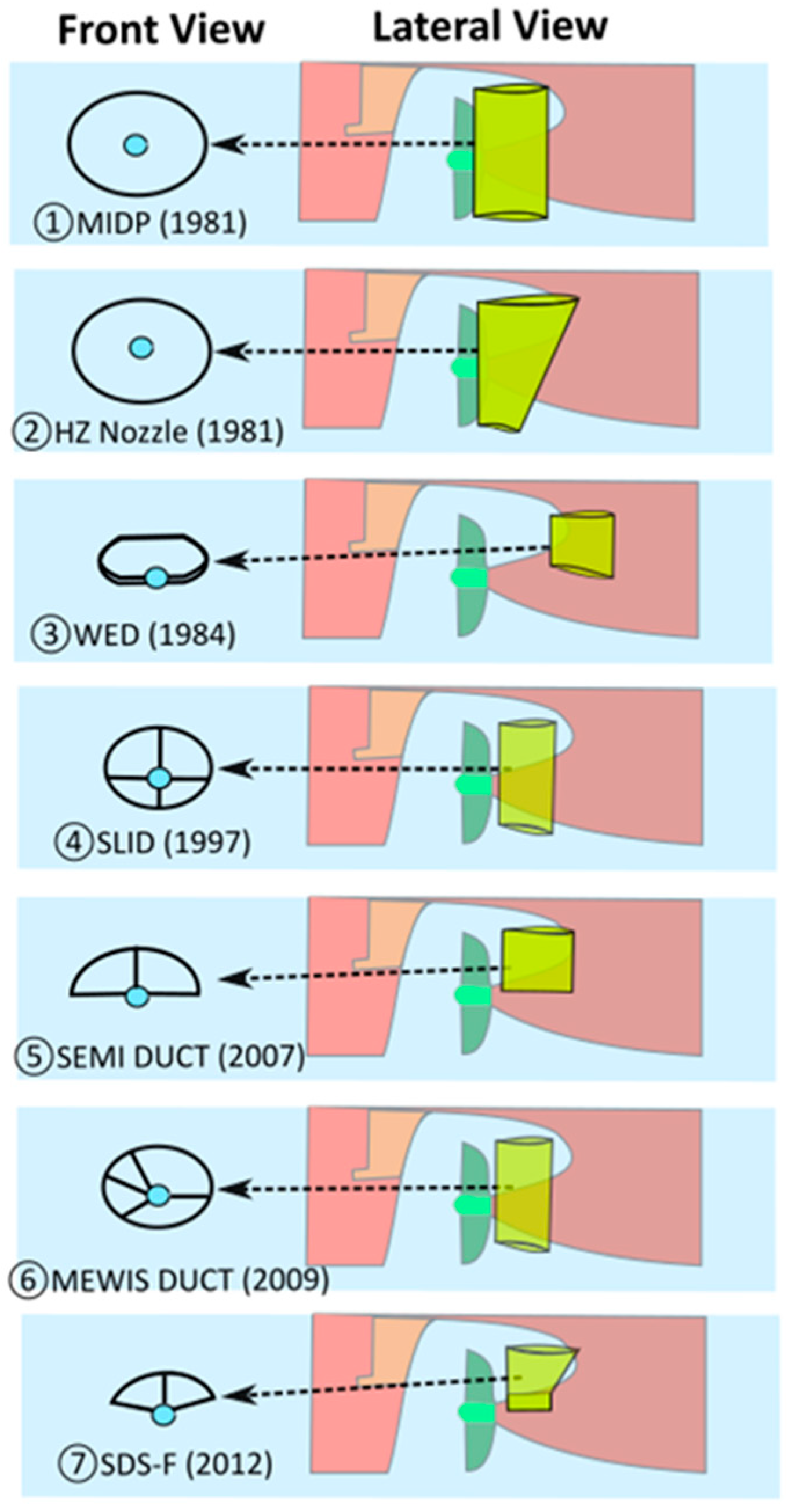
3.2. Pre-Swirl Duct (PSD)

One of the most widespread circular ducts is marketed by Becker Marine Systems GmbH & Co. (Hamburg, Germany) under the trademark Mewis duct® and consists of a wake equalizing duct combined with an integrated pre-swirl fin system, thus reflecting two operating conditions:
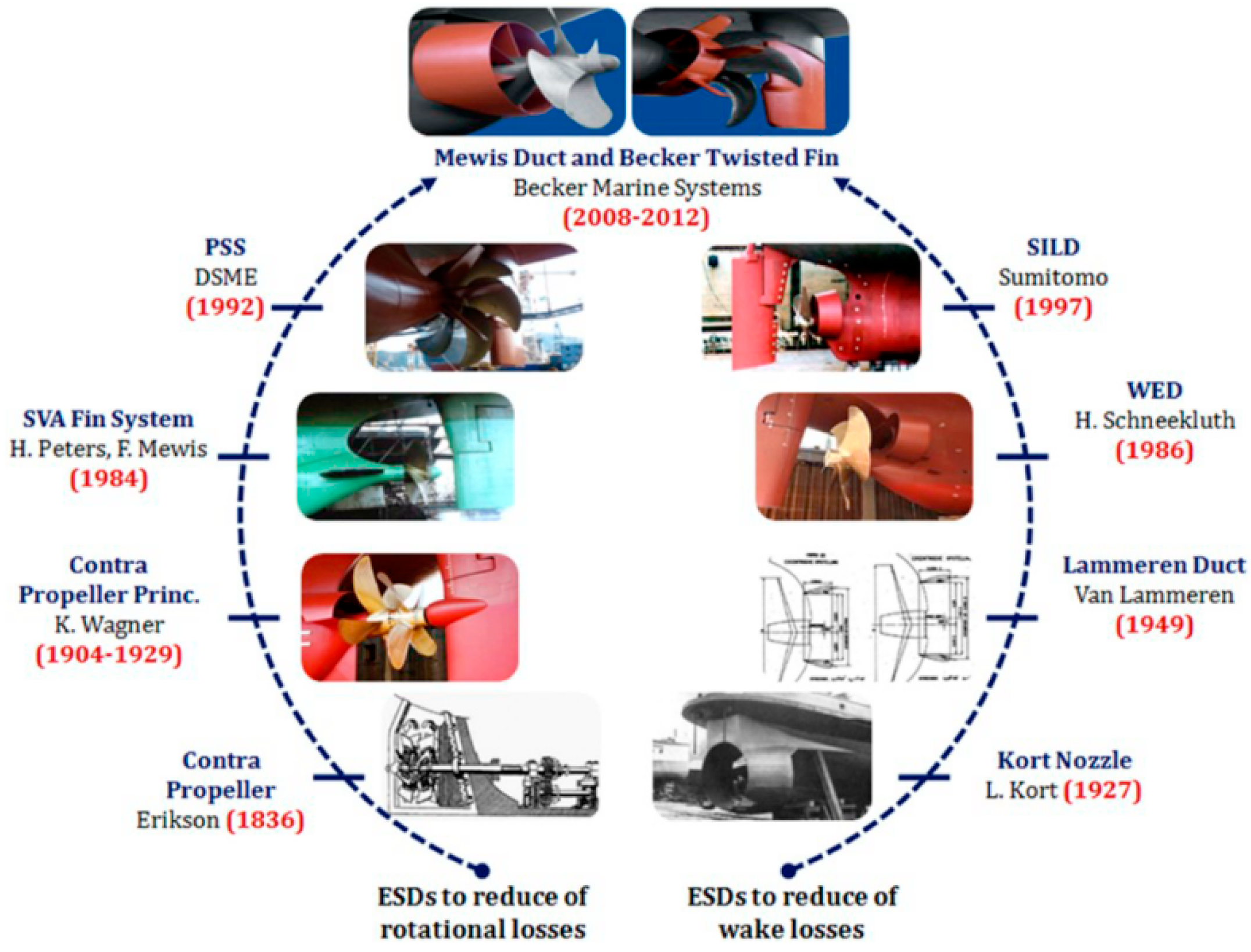
  • The first pre-duct principle, published by Van Lammeren in 1949 [20], promoted a duct ahead of the propeller, whose axis is above the shaft so that it guarantees a more equalized propeller inflow;
  • The contra-rotating propeller principle, known since 1824 [15], is based on a fin system within the duct to reduce rotational losses in the slipstream [21].
Figure 2 shows the evolution of the upstream ducted ESDs. The first commercial one is the Mitsui Integrated Duct Propeller (MDIP) by Mitsui Engineering & Shipbuilding (Tokyo, Japan) which is an annular steel nozzle, located immediately in front of the propeller and is slightly non-axisymmetric. Almost simultaneously, the Hitachi Zosen Nozzle (HZN) by Hitachi Zosen Corporation (Osaka, Japan) was developed. Its design is almost equal to the MIDP, except for a larger deviation from the axisymmetric condition [14].
Mewis Ship Hydrodynamics has developed the well-known PSD in cooperation with Becker Marine Systems GmbH & Co. Additionally, Becker Marine Systems GmbH & Co. has patented a twisted fins system, whose nozzle ring is significantly smaller than that of the Mewis duct® and has a flat profile with a much lower drag [20].
The idea of Van Lammeren was considered in 1984 by Schneekluth to invent the Schneekluth Wake Equalizing Duct (WED), and in 1997 by Sumitomo Heavy Industries to build the Sumitomo Integrated Lammeren Duct (SILD).
The WED consists of two half-ring ducts, which are fitted to the hull in front of the propeller. The SILD is geometrically similar to the MIDP, but instead of being fitted directly to the hull, it is mounted using struts and located eccentrically for the propeller shaft.
In 2007 a Semi-Circular Duct was launched by IHI Marine United, very similar to the SILD but with a semi-circular design instead of a circular one. F. Mewis and H. Peters in 1986 proposed a novel fin system (SVA Fin system) to decrease the rotational losses [22]. Daewoo Shipbuilding & Marine Engineering (DSME) has been manufacturing for decades Pre-Swirl Stator fins asymmetric and symmetric (Lee et al. [23]). The background history of Mewis duct® and Becker twisted fins® by Becker Marine Systems GmbH & Co. (Hamburg, Germany) is shown in Figure 3.
Several authors [25,26,27,28,29,30,31] have performed simulations over the JAPAN Bulk Carrier (JBC), while other researchers [32,33] have considered the general cargo carrier REGAL. Both these vessels have a U-shape hull that tends to have a relatively steep transition from the mid-ship section to the stern, and commonly suffer from the intensive bilge vortex in the wake field. Such non-uniform axial distribution of velocities generates axial losses in the flow, whose recovery is ensured by fitting a circular duct behind the stern.
Terwisga [9] tried to define the working principles of the PSDs. He first explained that to obtain a power reduction, there are essentially two options:
  • Enhancing the propeller efficiency.
  • Improving the propeller-hull interaction, to require less thrust.
Given the amount of literature about different ESDs, some researchers have been engaged in a sort of design challenge. Nowruzi et al. [24] highlighted the need for a sort of guidelines to design the geometrical parameters and position of the pre-swirl ducts independent of the inflow pattern.

3.3. Post-Swirl

The concept of a device located after a propeller assumes that the slipstream of a propeller has an annular shape. As contraction effects tend to leave an area of stagnant flow behind the hub, it is worthwhile to fill this area with a body. The post-swirl devices include several examples such as:
  • Propeller Boss Cap Fins (PBCF). The PBCF (Figure 4), originally developed by Mitsui OSK, consists of small fins attached to the boss cap fixed to the propeller. It recovers energy from the propeller hub vortex. The number of fins is the same as that of the propeller blades [34]. A study by Katayama et al. [35] included a list of typical profiles of general propeller caps and a specific propeller cap (contraction type) with fins (namely called ECO-Cap). The authors found an increase in the total efficiency due to the ECO-Cap was predicted by CFD and confirmed by the model test. The ECO-Cap prevents, as expected, the generation of the hub vortex. It is expected that this phenomenon makes the hub vortex weak, providing an overall improvement of about 1.28%. The PBCF performances are usually evaluated at the model scale.
  • Hub Vortex Vane (HVV). The HVV, jointly developed by SVA Postdam and Schottel, is a small vane propeller fixed to the tip of a cone-shaped boss cap. It may have more blades than the propeller [34,36].
  • Grim Vane Wheel. The Grime Vane Wheel is a freely rotating device located behind the propeller, and it is composed of a turbine section inside the propeller slipstream and a propeller section (vane tips) outside the propeller slipstream. It is even called “Grimsches Leitrad” and was first developed by Otto Grim. Its main function is to extract energy from the propeller slipstream in the turbine portion and convert this energy into additional thrust in the propeller portion. The vane wheel became unpopular after several reports of mechanical failures, most notably for the cruise ship Queen Elizabeth 2 in 1986. A joint project between Hyundai Heavy Industries (HHI) and Det Norske Veritas (DNV) restored its reputation by developing a modern vane wheel supported on the rudder [34,37].

4. ESD Performance Assessment: Scale Effects

According to the makers, these ESDs can guarantee fuel savings in the range of 2–8%. However, while a reliable estimate of potential fuel savings for ship owners is a necessary goal for a proper business project, these numbers were not well supported by experimental data. To certify this saving, in a retrofit project, it is necessary to compare power performance after and before the ESD installation.
The ways to estimate the ESD performance are based on the model test, sea trials, and/or CFD simulations in model and full scale. However, when evaluating the potential savings for these specific devices, the designer/shipowners must be cautious when savings are achieved by the ship model, as scale effects can occur.
About the sea trials, it is always difficult to judge the results as experimental uncertainties from sea trials measurements and the efficiency gains by the ESDs are often in the same order of magnitude [38,39]. Historically, due to a lack of accurate measuring systems/procedures, the energy-saving potential of the devices could not be verified in ship trials. It is always difficult to judge sea trial results because the efficiency gains by the ESDs are often in the same order of magnitude as the uncertainties of the sea trial measurements [13].
The authors suggest the use of advanced statistical methods to evaluate the real ESD performance, as reported in [40,41] these methods can use automatic data, acquired on board modern ships for a long period after and before ESD installation, during standard ship voyages.
The usual practice is to scale the nominal wake field from model scale to ship scale and then find the effective wake field at ship scale from the derived effective wake model. However, determining the full-scale wake from model tests is a great challenge, especially for WED. There are existing methods that are based on available model data and use CFD to compute the full-scale effect (meaning the difference in field distribution in model and full scale) to extrapolate the model measured wake values to full scale. Doubts exist about the real efficiency gains achieved by fitting ESDs because some sea trial measurements do not show any improvement directly, although large efficiency gains have been measured in the model scale. Therefore, it is necessary to tune the model wake field to a full-scale wake.
Ideally, both model-scale and full-scale resistance predictions must be carried out. The main concern is that comparison with experimental data requires the experimental uncertainty to be known, as any distortion may negatively affect the full-scale validation trials.
The scale effect is meant as the dependence of the flow field and the fluid forces on Reynolds Number (Re):
Re = V s · L W L ν
where V s is the ship speed, L W L is the wetted length of the ship, and ν is the kinematic viscosity of the water. The viscous flow around the ship is strongly influenced by Re [26,42]. The small dimensions of ESDs in model tests lead to small local Re, and consequently to a considerable exaggeration of viscosity effects, that are difficult to evaluate.
The Re for model tests are generally in the range 10 6 to 10 7 and the ships work mainly at Re around 10 9 . Therefore, even though full-scale analysis should represent the main way, the full-scale test procedures (so as the standardized correction methods) are not sufficiently accurate to reveal unequivocally the difference in required power for ESDs retrofitted ships.
The main causes of the scale effects on the ESDs under analysis are:
  • hull boundary layer, the thickness of which is greater in model scale than in ship scale. The duct is partly inside the boundary layer of the bottom;
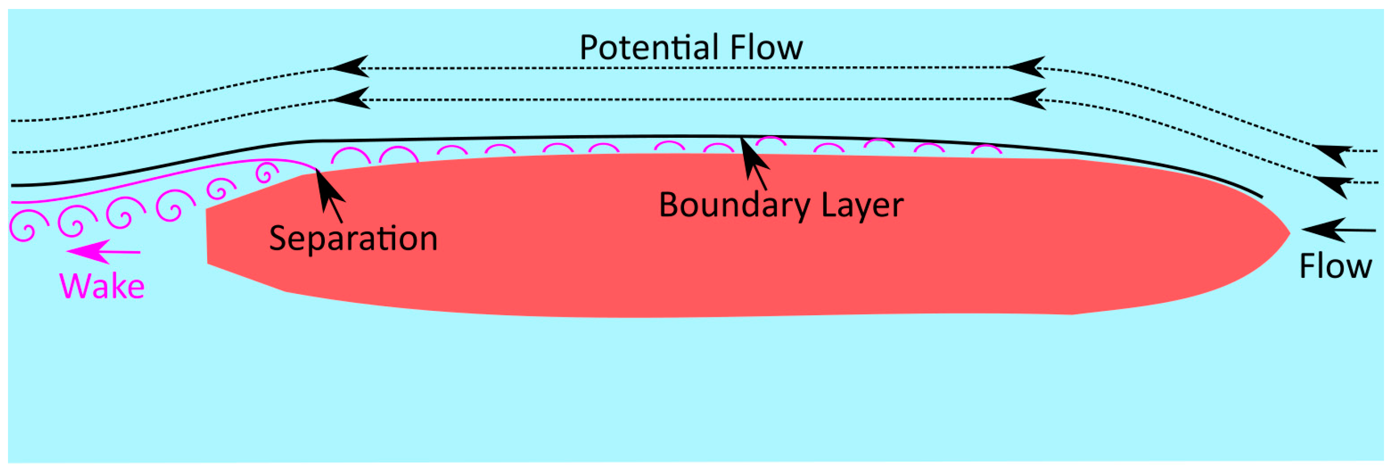
  • separation of the aft flow that occurs on the model scale may not occur at full scale. Therefore, depending on the scale, parts of the duct may or may not be within the separation area;
  • friction coefficient ( C f ), whose dependence on the Re ( C f ) is about two times larger in model scale) causes differences in the resistance between model and true size. Its effect on the propeller load can be eliminated during model tests (e.g., by means of a pulling force), but the effect on the viscous wake in the propeller position remains. If the ESD acts by changing the viscous trail, its effect should be greater in the model than in the full scale. Much less is the space between the hull and the ESD, and much more significant is the increase of local resistance [16].
Several researchers investigated this point, for instance, Friesch et al. [43] violated Froude’s scaling law by conducting tests on a single screw ship model fitted with a WED in a large cavitation tunnel at the highest possible water speed. They found that wake equalizing ducts may result in energy saving at full scale, but it was difficult to prove a similar effect by model tests at Froude number equivalent speed. On the contrary, tests performed at higher Reynolds numbers in a large cavitation tunnel indicated a different behaviour of energy-saving with the test speed.
Ok [44], by investigating the scale effect of Schneekluth duct on the propulsion performance of a ship, raised doubts about the real effectiveness of this device (and claimed by the eponymous inventor). For validation purposes, he compared his results with those calculated by Friesch et al. [43], as the ship parameters of interest were the same. Therefore, the usual scaling procedure is even less reliable as it neglects the induced axial flow portion, leading to a mismatch between results respectively for the model- and full-scale wake.
The procedure was even described by the specialist committee on the scaling of the wake field [45], which summarized all the wake survey procedures, reported the absence of appropriate wake scaling methods for ships with WED, recommended that self-propulsion tests should be performed at higher values of Re to reduce the scaling of flow separation effects.
Van et al. [46] proposed two alternative procedures for performance prediction for ships fitted with pre-swirl stators, that follow the ITTC’78 method [47]. Choi et al. [48] developed an ESD and compared quasi-propulsive efficiencies predicted by modified ITTC’78 and ITTC’99 methods. Park et al. [49] examined the existing methods ITTC’78 and ITTC’99 [50], then proposed a new wake prediction procedure for full-scale ships. The ITTC’78 and ITTC’99 formulas are shown in Equations (8) and (9), respectively.
w S = ( t + 0.04 ) + ( w M t 0.04 ) C F S + C A C F M
where w S is effective wake with a pre-swirl device (or stator, in general) in full scale, w M is effective wake without a pre-swirl device in model scale, t is thrust deduction with a pre-swirl device in model scale.
w SS = ( t MO + 0.04 ) + ( w MO t MO 0.04 ) C F S + C A C F M + ( w MS w MO )
where w S S is effective wake with a pre-swirl device in full scale, w M S is effective wake with a pre-swirl device in model scale, w M O is effective wake without a pre-swirl device in model scale, t M O is thrust deduction without a pre-swirl device in model scale. The first part of the formula is exactly the ITTC’78 and the last term is separately added because the tangential velocity by the pre-swirl stator should not be scaled. A modified version of the ITTC’99 has been proposed by Kim et al. [51] including a different scaling procedure for tangential and axial wake velocity according to the vessel type as well as the device type.
According to Schuiling [14], the higher suction values of the WED along with those of the propeller lead to an augmented thrust deduction, which absorbs partially or totally the additional thrust, so that any potential effect of the duct is set to zero.
Nevertheless, as early as 1950, there was a conviction that only the viscous part of the thrust deduction might generate additional energy losses by reducing the total pressure head along a streamline. The potential term, to which in addition a WED net thrust gain should be accounted for, could be actually a kind of internal force of the ship propulsion system and might not generate additional losses in the flow. The duct is seen as a part of the propulsion system [45].
The work by Kim et al. [51] gave an explanation based on Figure 5. As reported in case (a) the induced velocities due to the suction effect are neglected thus allowing for linearity between oncoming velocity and thrust. The angle of attack α depends on the oncoming velocity on the propeller plane (VA) and the speed of revolution (2пnr) and the rotational velocity is kept the same in the open water condition as in behind the ship condition (VA is linear to the thrust). Case (b) accounts for the presence of a Pre-Swirl device, which causes axial flow retardation (Vx) and a counter-swirl against the inflow of the propeller (Vt). The latter component is a potential term rather than viscous, hence should not be scaled. The ITTC’78 and ’99 methods are considered not directly applicable as it applies to scale to the total amount of the nominal wake, thus leading to results that are minor compared to the full-scale ones. The proposed procedure avoids scaling the tangential velocity to full scale [51].
Eventually for correcting the errors associated with the scale effects in the nominal wake field measurements of a ship model, a further model that is non-geometrically similar (Geosim procedure) to the full-scale ship but matches its wake field can be used. Its name is Smart Dummy Model (or Smart Ship Model). The SDM correction method helps to simulate the full-scale wake in model scale tests, thus offering a new pathway for correcting the errors associated with the scale effects in the nominal wake field measurements of a ship model [18].
Even the PBCF performances are affected by the scale effect. Indeed, the PBCF performances are estimated, usually, in model scale and the scaling process follows the same procedures implemented for scaling the propeller performance curves, as explained by the ITTC specialist committee on Energy Saving Devices [52] and by Xu et al. [53]. Generally, the full-scaling effect increases the PBCF performance of abt. 1% as suggested in [35,36].

5. CFD Simulations for ESD Devices

Since then, CFD has continued to evolve, and many researchers have begun to rely on it because of its ability to apply much greater Re. Thanks to the enormous computing power available today, there are increasing numbers of attempts to resolve viscous sublayers.
When possible, it is recommended to perform direct calculations of full-scale wake with numerical codes [54], and a direct comparison of full-scale CFD simulations with sea trials, for which there seems to be an ongoing effort among researchers, would be a net advantage. As underlined by Larsson [54] performing direct calculations of full-scale wake with numerical codes is the best-recommended practice. In an experiment about a pre-swirl stator with three fins, Hasselaar et al. [5] showed good agreement between results obtained in speed/power trials and CFD full-scale simulations.

5.1. Propeller Modelization

In the evaluation of the effectiveness of the ESD devices with the CFD simulations, the propeller modelization plays a not negligible role.
The most commonly used propulsion model is the body force propeller method [45] wherein a detailed propeller model is unnecessary, whereby an actuator disk allows for accurate results with less effort. Furcas et al. [26] reviewed the most utilized actuator disk by varying radially the axial load, about the JBC propeller’s circumferentially averaged inflow computed with Boundary Element Method (BEM) [26]. The actuator disk reproduces the propeller through a force distribution that integrates numerically both thrust and torque [55].
Therefore, even if the body-force method can help simulate self-propulsion more easily and quickly than a fully discretized based method could do, it can only simulate the distribution of the thrust and torque. Employing the complex geometry of the propeller (fully resolved propeller) could not be so convenient as it implies a strong computational effort. Therefore, simplified approaches are necessary to make RANSE analyses usable throughout the design process [26]. An alternative is to model the lift and drag of the blades along radius by separating them into finite elements, each having a certain foil shape and attitude to the oncoming flow. Such an approach is the so-called Blade Element Momentum Theory (BEMT) [24,56].
In recent years, viscous flow simulations around the hull coupled with potential flow-based propeller models have become a popular choice for numerical self-propulsion simulations. Usually, field methods solving the Reynolds Averaged Navier–Stokes (RANS) equations are used for the hull part, and panel methods (boundary element methods) are a common choice for the propeller calculations, as they allow for a decent representation of the flow physics while only requiring limited computational effort. Computational approaches using this combination of tools are then often referred to as RANS-BEM coupling. However, as reported by Terwisga [10] and Prins et al. [16], the RANS-BEM coupling approach is not likely to accurately account for an inclined flow or strong velocities, as it does not completely capture the effect of an ESD. The fully RANS method is more suitable to offer a better resolution, thus providing a more accurate propeller modelling, even if the smaller modelling error must be paid for by preparation and computational time. Queutey et al. [57] performed hybrid RANS-BEM self-propulsion computations on a tanker without any retrofitted device; later Schuiling et al. [14] considered the same tanker without a Blade efficiency improving Stator Duct (BSD) but by conducting unsteady RANS simulations. By a comparison, between his results and those of Queutey et al. [57], a similarity was found despite the different approaches used. However, including a stern device would lead to differences between the two simulations [14,57].

5.2. Turbulence Models

Viscous flow is an issue, especially in the case of self-propulsion. Turbulent flows are characterized by fluctuating velocity fields. Larsson et al. [54] explained that the type of turbulence model plays a crucial role in wake prediction. Maasch et al. [25] declared that it is the turbulence closure that dictates the level of detail in wake flow prediction. Outcomes from the Gothenburg 2010 Workshop support the argument that turbulence models play an important role but continue to add that the grid resolution should be sufficiently fine to capture certain details. In a choice of the turbulence model, it is necessary to consider parameters such as the physics encompassed in the flow, the established practice for a specific class of problem, the level of accuracy required, the available computational resources, and the amount of time available for the simulation. The k-ε model and the Shear Stress Transportation (SST) k-ω are two equation turbulence models that successfully managed to capture the general flow around the ship [49]. These models, however, were not fully able to predict certain wake flow characteristics, especially vortex structures. The more advanced Reynolds Stress Models (RSM) are better suited for capturing and simulating stronger bilge vortices [29] but are, however, computationally expensive, and less robust. In solving wake features, the SST k-ω is deemed more adequate for a larger set of simulations as it provides a good compromise between k-ε methods and more complex RSM models [24,58,59]. Guiard et al. [60] employed the RSM turbulence model but they agreed that the SST k-ω model is simpler and more effective as the RSM model is very time-consuming, requires a high-quality mesh, and is not straightforward if used combined with the Volume of Fluid (VoF) method.

6. ESD Optimization Methods

For each project to which an ESD is applied, an individual and optimal geometry of the device must be achieved. This can be done with the support of CFD calculations, which require the complete availability of geometry information for the hull and the propeller, as well as the most relevant self-propulsion data for the assigned design point. The optimization process, i.e., the right choice of ESD, which can ensure the highest possible power saving for the ship under consideration, is largely based on numerical simulations as it is relatively easy to extract from them almost all the flow details useful for the design process. The typical approach, summarized by De Jong et al. [13] follow the steps:
  • Select retrofit using data indicated by the owner/supplier;
  • Optimize by applying CFD and check viability;
  • Model test to validate;
  • Trial to confirm.
It is worth mentioning that any step, the procedure can be shifted. For example, if ESD has already been selected, the parameters to be studied and the comparison with the reference case will be lower.
For many studies [61,62,63,64,65], the wakefield design is the most preferred target of any optimization effort, rather than design improvement of ESD structure.
Dang et al. [38] raised a suspicion that aiming to achieve the highest ESD thrust, through better optimization of the ESD geometry during the design stage with the CFD tools, may not result in energy saving [18], as PDS and PSS do not provide demonstrable net thrust gains.
Tahara et al. [62] developed a system whose input is a desired specific wake distribution on the propeller plane, whereas the output is a hull form yielding wake distribution close to the input data.
A recurrent procedure is to improve the geometry at the model test stage [56] or the Simulation-Based Design Optimization (SBDO) approach, an automatic and iterative design process aiming to operate a change of geometric properties within the simulation itself. Furcas et al. [26] applied the SBDO in model scale, thus neglecting the scale effects that play a significant role in the performance of such devices. They encouraged a simultaneous design of the WED and the propeller to exploit the maximum from the mutual interactions: redesigning the propeller with the custom WED can exploit the maximum from the mutual interactions.
The experimental tests for the evaluation of the ESDs follow the standard approach of the towing tank tests. The main differences are related to the specific arrangement around the ESD for the forces and wake evaluation.

7. Conclusions

The interest in ship energy saving devices nowadays is constantly growing due to the regulatory GHG emission reduction targets. Indeed, the energy-saving devices represent a first and a strategic tool for the shipping decarbonization process.
The present review paper is focused on analysing the recent and relevant studies related to the hydrodynamic energy-saving devices applied on the stern part of, mainly, the full-bodied hulls, e.g., bulkers, tankers, and cargo ships. A detailed description of the energy-saving devices under analysis has been provided by dividing them into three groups based on where are located on the targeted ships: (pre-swirl stator, pre-swirl duct, and post-swirl).
The review highlighted how these three groups of stern hydrodynamic energy-saving devices can improve the hull-propeller interaction and the propulsive efficiency, acting in different physical ways.
The estimation of the performance gain of the stern hydrodynamic energy-saving devices is affected by full-scaling effects. Different methods and approaches have been developed and proposed over the last decades including even the application of CFD tools to estimate directly the full-scale performances. The CFD is nowadays largely implemented in the analysis of the energy-saving devices in the design and verification phases including the optimization process as well.
Furthermore, a not negligible point that needs to be considered with the ESD (mainly PSD and PSS) application is the effect on the propeller and, specifically, the effect on the main engine-propeller matching, because the propeller margin is influenced by the ESD installation and specific/detailed analysis is suggested for each ESD application.
The following table (Table 2), extracted from the ITTC 1999 [50] and updated including more recent results available in other overview analyses (e.g., [52]), comprise all the energy-saving devices under analysis in the present review. In the table, an expected saving range for model scale and sea trials of the different stern hydrodynamic energy saving devices has been provided. This table might be an interesting way, to sum up, the present review work.

Author Contributions

S.M. and F.S. worked for conceptualization; F.S. for methodology, investigation, resources, data curation and writing; F.S., S.M., R.N.B. and L.V. working for original-draft preparation; S.M., L.V. and R.N.B. writing—review and editing; R.N.B. working for visualization; S.M. for supervision; M.D.C. for project administration, funding acquisition and management. All authors have read and agreed to the published version of the manuscript.

Funding

This research received no external funding.

Informed Consent Statement

Not applicable.

Conflicts of Interest

The authors declare no conflict of interest.

References

  1. Tien, A. Reducing Greenhouse Gas Emissions from Ships through analysis of marginal abatement cost (MAC) curves. Glob. J. Eng. Sci. Res. 2018, 17. Available online: https://globaljournals.org/GJSFR_Volume17/3-Reducing-Greenhouse-Gas-Emissions.pdf (accessed on 31 March 2022).
  2. European Union Law. Available online: https://eur-lex.europa.eu/legal-content/EN/TXT/?uri=CELEX:52021PC0558 (accessed on 21 November 2021).
  3. International Chamber of Shipping, «EUROPEAN UNION MRV REGULATION» August 2020. Available online: https://www.ics-shipping.org/wp-content/uploads/2020/08/ics-guidance-on-eu-mrv.pdf (accessed on 13 March 2022).
  4. Mallouppas, G.; Yfantis, E. Decarbonization in Shipping Industry: A Review of Research, Technology Development, and Innovation Proposals. J. Mar. Sci. Eng. 2021, 9, 415. [Google Scholar] [CrossRef]
  5. Hasselaar, T.W.; Xing-Kaeding, Y. Evaluation of an energy-saving device via validation speed/power trials and full-scale CFD investigation. Int. Shipbuild. Prog. 2017, 63, 169–195. [Google Scholar] [CrossRef]
  6. RESOLUTION MEPC.333(76), ANNEX 7; Guidelines on the Method of Calculation of the Attained Energy Efficiency Existing Ship Index (EEXI). IMO: London, UK, 2021.
  7. BIMCO. 2020. Available online: https://bi-cd02.bimco.org/news/environment-protection/20200219-eexi-proposal-to-imo (accessed on 21 December 2021).
  8. Rutherford, D.; Mao, X.; Comer, B. Potential CO2 Reductions under the Energy Efficiency Existing Ship Index; International Council on Clean Transportation (ICCT): Washington, DC, USA, 2020. [Google Scholar]
  9. Olsen, A.S. Energy coefficients for a propeller series. Ocean Eng. 2004, 31, 401–416. [Google Scholar] [CrossRef]
  10. Terwisga, T. On the working principles of Energy Saving Devices. In Proceedings of the Third International Symposium on Marine Propulsors (SMP’13), Launceston, Australia, 5–8 May 2013. [Google Scholar]
  11. Bulten, N.W.H.; Stoltenkamp, P.W.; van Hooijdonk, J.J.A. Efficient propeller designs based on full-scale CFD simulations. In Proceedings of the International Conference on High Performance Marine Vehicles, Athens, Greece, 3–5 December 2014. [Google Scholar]
  12. Mewis, F. A novel power-saving device for full form vessels. In Proceedings of the International Symposium on Marine Propulsion, Trondheim, Norway, 22–24 June 2009. [Google Scholar]
  13. de Jong, J.H.; Zondervan, G.J.D. A Framework for Energy Saving Device (ESD) Decision Making; MARIN: Wageningen, The Netherlands, 2011. [Google Scholar]
  14. Schuiling, B.; van Terwisga, T. Hydrodynamic working principles of Energy Saving Devices in ship propulsion systems. Int. Shipbuild. Prog. 2016, 63, 255–290. [Google Scholar] [CrossRef]
  15. Carlton, J.S. Marine Propellers and Propulsion, 4th ed.; Butterworth-Heinemann: Oxford, UK, 2019. [Google Scholar]
  16. Prins, H.J.; Flikkema, M.B.; Schuiling, B.; Kaeding, Y.X.; Voermans, A.A.M.; Müller, M.; Coache, S.; Hasselaar, T.W.F.; Paboeuf, S. Green retrofitting through optimisation of hull-propulsion interaction—GRIP. In Proceedings of the 6th Transport Research Arena (TRA), Warsaw, Poland, 18–21 April 2016. [Google Scholar]
  17. Flikkema, M.; Goorden, B.; Cervicato, C.; Verhulst, M.; Schuiling, B.; Janse, G.; Voermans, A.; de Bot, B.; Terwisga, T.; Portolano, A.; et al. Design and demonstration of an Energy Saving Device for a ship with controllable pitch propeller. In Proceedings of the 8th Transport Research Arena (TRA), Helsinki, Finland, 27–30 April 2020. [Google Scholar]
  18. Dang, J.; Chen, H.; Guoxiang, D.; van der Ploeg, A.; Hallmann, R.; Mauro, F. An exploratory study on the working principles of Energy Saving Devices (ESDs). In Proceedings of the Symposium on Green Ship Technology (Greenship’11), Wuxi, China, 10–11 October 2011. [Google Scholar]
  19. Nadery, A.; Ghassemi, H.; Chybowski, L. The effect of the PSS configuration on the hydrodynamic performance of the KP505 propeller behind the KCS. Ocean Eng. 2021, 234, 109310. [Google Scholar] [CrossRef]
  20. The Maritime Executive. Available online: https://www.maritime-executive.com/corporate/New-EnergySaving-Device-The-Becker-Twisted-Fin (accessed on 16 July 2020).
  21. Force Technology. Available online: https://forcetechnology.com/en/cases/how-a-fin-and-a-duct-save-fuel (accessed on 19 July 2020).
  22. Mewis, F.; Peters, H.E. Power savings through a novel fin system. In Proceedings of the 15th SMSSH Conference, Varna, Bulgaria, 6–11 October 1986. [Google Scholar]
  23. Lee, J.T.; Kim, M.C.; Suh, J.C.; Kim, S.H.; Choi, J.K. Development of a Pre Swirl Stator Propeller System for Improvement of Propulsion Efficiency: A Symmetric Stator Propulsion System; Society of Naval Architects of Korea (SNAK): Busan, Korea, 1992. [Google Scholar]
  24. Nowruzi, H.; Najafi, A. An experimental and CFD study on the effects of different pre-swirl ducts on propulsion performance of series 60 ship. Ocean Eng. 2019, 173, 491–509. [Google Scholar] [CrossRef]
  25. Maasch, M.; Mizzi, K.; Atlar, M.; Fitzsimmons, P.; Turan, O. A generic wake analysis tool and its application to the Japan Bulk Carrier test case. Ocean Eng. 2019, 171, 575–589. [Google Scholar] [CrossRef] [Green Version]
  26. Furcas, F.; Vernengo, G.; Villa, D.; Gaggero, S. Desing of Wake Equalizing Ducts using RANSE-based SBDO. Appl. Ocean Res. 2020, 97, 102087. [Google Scholar] [CrossRef]
  27. Bekhit, A.S. Numerical simulation of the ship self-propulsion prediction using body force method and fully discretized propeller model. IOP Conf. Ser. Mater. Sci. Eng. 2018, 400, 042004. [Google Scholar] [CrossRef] [Green Version]
  28. Windén, B.; Huang, Z.; Kawamura, T. Comparative self-propulsion simulations of the JBC bulk carrier. In Proceedings of the Japan Society of Naval Architects and Marine Engineers (JASNAOE) Spring Meeting, Kobe, Japan, 25 May 2015. [Google Scholar]
  29. Andersson, J.; Hyensjö, M.; Eslamdoost, A.; Bensow, R. CFD simulations of the Japan Bulk Carrier Test case. In Proceedings of the Numerical Towing Tank Symposium, Cortona, Italy, 27–29 September 2015. [Google Scholar]
  30. Korkmaz, K.B. CFD Predictions of Resistance and Propulsion for the Japan Bulk Carrier (JBC) with and without an Energy Saving Device. Master’s Thesis, Chalmers University of Technology, Gothenburg, Sweden, 2015. [Google Scholar]
  31. Bakica, A.; Vladimir, N.; Ančić, I. Improving ship energy efficiency performance by energy-saving devices. In Proceedings of the International Conference on Smart & Green Technology for the Future of Marine Industries (SMATECH 2019), Glasgow, UK, 11–12 July 2019. [Google Scholar]
  32. Jasak, H.; Vukcevic, V.; Gatin, I.; Lalovic, I. CFD validation and grid sensitivity studies of full-scale ship self-propulsion. Int. J. Nav. Archit. Ocean Eng. 2018, 11, 33–43. [Google Scholar] [CrossRef]
  33. Vukcevic, V.; Jasak, H.; Gatin, I.; Uroic, T. Ship scale self-propulsion CFD simulation results compared to sea trials measurements. In Proceedings of the International Conference on Computational Methods in Marine Engineering, Nantes, France, 15–17 May 2017. [Google Scholar]
  34. Hochkirk, K.; Bertram, V. Options for fuel-saving for ships. In Proceedings of the Mare Forum: Maritime Transportation of Energy, Houston, TX, USA, 19 February 2010. [Google Scholar]
  35. Katayama, K.; Yoshihisa, O.; Okazaki, A. Optimization of the propeller with ECO-cap by CFD. In Proceedings of the International Symposium on Marine Propulsors (SMP’15), Austin, TX, USA, 31 May–4 June 2015. [Google Scholar]
  36. Shiffbau-Versuchsanstalt Postdam (SVA). Available online: https://www.sva-potsdam.de/en/energy-saving-devices/ (accessed on 22 March 2022).
  37. Safety4Sea. Available online: https://safety4sea.com/hhi-and-dnv-gl-take-a-fresh-look-at-grims-vane-wheel/?__cf_chl_jschl_tk__ (accessed on 25 July 2020).
  38. Dang, J.; Chen, H.; Guoxiang, D. An exploratory study on the working principles of Energy Saving Devices (ESDs)—PIV, CFD investigations and ESD design guidelines. In Proceedings of the 31st International Conference on Ocean, Offshore and Arctic Engineering (OMAE12), Rio de Janeiro, Brazil, 10–15 July 2012. [Google Scholar]
  39. Guo, C.; Wu, T.; Zhang, Q.; Luo, W.; Su, Y. Numerical simulation and experimental studies on aft hull local parameterized non-GEOSIM deformation for correcting scale effects of nominal wakefield. Brodogradnja/Shipbuilding 2017, 68, 77–96. [Google Scholar]
  40. Bocchetti, D.; Lepore, A.; Palumbo, B.; Vitiello, L. A Statistical Approach to Ship Fuel Consumption Monitoring. J. Ship Res. 2015, 59, 162–171. [Google Scholar] [CrossRef]
  41. Bocchetti, D.; Lepore, A.; Palumbo, B.; Vitiello, L. A statistical control of the ship fuel consumption. In Proceedings of the Design & Operation of Passenger Ship, London, UK, 20–21 November 2013. [Google Scholar]
  42. Heinke, H.; Hellwig-Rieck, K. Investigation of scale effects on ships with a Wake Equalizing Duct or with Vortex Generator Fins. In Proceedings of the Second International Symposium on Marine Propulsors, Hamburg, Germany, 15–17 June 2011. [Google Scholar]
  43. Friesch, J.; Johannsen, C. Propulsion optimization tests at high Reynolds numbers. In Transactions; The Society of Naval Architects and Marine Engineers (SNAME): Jersey City, NJ, USA, 1994; Volume 102, pp. 1–21. [Google Scholar]
  44. Ok, J.P. Numerical Investigation of Scale Effects of Schneekluth’s Duct; TU Hamburg-Harburg: Hamburg, Germany, 2004. [Google Scholar]
  45. Final report of the specialist committee on scaling of wakefield. In Proceedings of the International Towing Tank Conference (ITTC), Rio de Janeiro, Brazil, 28 August–3 September 2011.
  46. Van, S.H.; Kim, M.C.; Lee, J.T. Some remarks on the powering performance prediction method for a ship equipped with a pre swirl stator propeller system. In Proceedings of the International Towing Tank Conference (ITTC), Daejeon, Korea, 19–25 September 1993. [Google Scholar]
  47. 7.5-02-03-01.4; Performance, Propulsion 1978 ITTC Performance Prediction Method. ITTC: Zürich, Switzerland, 2017.
  48. Choi, J.E.; Kim, J.H.; Choi, B.J.; Lee, S.B.; Chung, S.H.; Seo, H.W. Development of energy-saving devices for a hull slow speed ship through improving propulsion performance. In Proceedings of the 12th International Symposium on Practical Design of Ships and other Floating Structures, Changwon, Korea, 20–25 October 2013. [Google Scholar]
  49. Park, S.; Oh, G.; Rhee, S.H.; Koo, B.; Lee, H. Full-scale wake prediction of an Energy Saving Device by using Computational Fluid Dynamics. Ocean Eng. 2015, 101, 254–263. [Google Scholar] [CrossRef]
  50. ITTC. Final Report of the Specialist Committee on Unconventional Propulsors; ITTC: Seoul, Korea; Shangai, China, 1999. [Google Scholar]
  51. Kim, M.C.; Shin, Y.J.; Lee, W.J.; Lee, J.H. Study on extrapolation method for self-propulsion test with pre-swirl device. In Proceedings of the International Symposium on Marine Propulsion (SMP’17), Espoo, Finland, 12–15 June 2017. [Google Scholar]
  52. ITTC. Final Report and Recommendations to the 28th ITTC—The Specialist Committee on Energy Saving Devices; ITTC: Wuxi, China, 2017. [Google Scholar]
  53. Xu, L.; Wan, D. Numerical Investigation of Scale Effect for Propeller Boss Cap Fins. In Proceedings of the Twenty-Eighth International Ocean and Polar Engineering Conference (ISOPE), Sapporo, Japan, 10–15 June 2018. [Google Scholar]
  54. Larsson, L.; Stern, F.; Bertram, V. Benchmarking of Computational Fluid Dynamics. J. Ship Res. 2003, 47, 63–81. [Google Scholar] [CrossRef]
  55. MARIN. Available online: https://www.marin.nl/jips/refit2save (accessed on 21 June 2020).
  56. Shin, H.J.; Lee, J.S.; Han, M.R.; Hur, E.B.; Shin, S.C. Numerical and experimental investigation of conventional and unconventional pre-swirl duct for VLCC. Int. J. Nav. Archit. Ocean Eng. 2013, 5, 414–430. [Google Scholar] [CrossRef] [Green Version]
  57. Queutey, P.; Gulmineau, E. A comparison between full RANSE and coupled RANSE-BEM approaches in ship propulsion performance prediction. In Proceedings of the 32nd International Conference on Ocean, Offshore and Arctic Engineering (OMAE), Nantes, France, 9–14 June 2013. [Google Scholar]
  58. Go, J.S.; Yoon, H.S.; Jung, J.H. Effects of a duct before a propeller on propulsion performance. Ocean Eng. 2017, 136, 54–66. [Google Scholar] [CrossRef]
  59. Baek, D.G.; Jung, J.H.; Yoon, H.S. Effects on the advance ratio on the evolution of propeller wake. In Proceedings of the International Conference on Environment, Energy, Ecosystems and Development (EEEAD’13), Energy, Venice, Italy, 28–30 September 2013. [Google Scholar]
  60. Guiard, T.; Leonard, S.; Mewis, F. The Becker Mewis duct challenges in full-scale design and new development for fast ships. In Proceedings of the Third International Symposium on Marine Propulsors (smp’13), Launceston, Australia, 5–8 May 2013. [Google Scholar]
  61. Ichinose, Y.; Tahara, Y. A wakefield design system utilizing a database analysis to enhance the performance of energy-saving devices and propellers. J. Mar. Sci. Technol. 2018, 24, 1119–1133. [Google Scholar] [CrossRef]
  62. Tahara, Y.; Ichinose, Y.; Kaneko, A.; Kasahara, Y. Variable decomposition approach applied to multi-objective optimization for minimum powering of commercial ships. J. Mar. Sci. Technol. 2018, 24, 260–283. [Google Scholar] [CrossRef]
  63. van der Ploeg, A.; Raven, H.C. CFD based optimization for minimal power and wakefield quality. In Proceedings of the International Symposium on practical design of ships and other floating structures, Rio de Janeiro, Brazil, 19–24 September 2010. [Google Scholar]
  64. Chen, P.F.; Huang, C.H. An inverse hull design problem in optimizing the desidered wake of a ship. J. Ship Res. 2002, 46, 138–147. [Google Scholar] [CrossRef]
  65. Stuck, A.; Kroger, J.; Rung, T. Adjoint based hull design for wake optimization. Ship Technol. Res. 2011, 58, 34–44. [Google Scholar] [CrossRef]
Figure 1. Boundary layer for a displacement ship.
Jmse 10 00574 g001
Figure 2. Pre-swirl ducts over the years.
Jmse 10 00574 g002
Figure 3. History of Mewis duct® and Becker twisted fins® (Becker Marine Systems GmbH & Co. KG, Hamburg, Germany) [24].
Jmse 10 00574 g003
Figure 4. Post-swirl devices: PBCF [15].
Jmse 10 00574 g004
Figure 5. Change of inflow angle at the propeller blade section on account of the induced ESD velocity. Case (a) velocities and angle of attack on propeller section without ESD; Case (b) velocities and angle of attack on propeller with ESD (Pre-Swirl device).
Jmse 10 00574 g005
Table 1. Propulsive factors.
η 0 η R η H
Axial losses
Rotational losses
Viscous losses
Non-uniformity (e.g., blades, etc.)
Wake adaption (represents the swirl kinetic energy added to the wake behind the propeller.)Propeller-hull
interactions
Table 2. Energy-saving devices under analysis (PRI is Pre-Rotation to the propeller Inflow, IPI means Improve Propeller Inflow, AFS means Alleviate Flow Separation, and DEP means Decrease Eddy after Propeller Cap).
TypeName of DeviceEnergy-Saving
Mechanism
Energy-Saving Rate%
Model Test/Sea Trials
Pre-swirl statorReaction finsPRI4–6/3–9
Pre-swirl ductBecker Mewis duct®IPI, AFS6–11/8
Fan-shaped Mewis duct®IPI, AFS6–11/9
Becker twisted fins®IPI, AFS6–11/10
Schneekluth duct/WEDIPI, AFS4–11/11
WED with Grothues spoilersIPI, AFS6–11/12
Unconventional half-circular ductIPI, AFS6–11/13
IPI, AFS6–11/14
Post-swirlPropeller boss cap finsDEP2–5/2–5
Hub vortex vaneDEP2–5/2–5
Publisher’s Note: MDPI stays neutral with regard to jurisdictional claims in published maps and institutional affiliations.

