
Review of the Influence of Oceanographic and Geometric Parameters on Oscillating Water Columns

 ,
,
Abstract
:1. Introduction
2. Research Methodology
3. OWCs: Concept, Elements, and Classification
3.1. OWC Elements
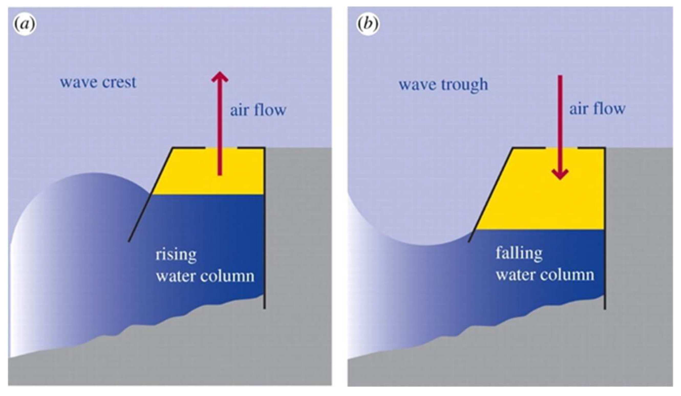
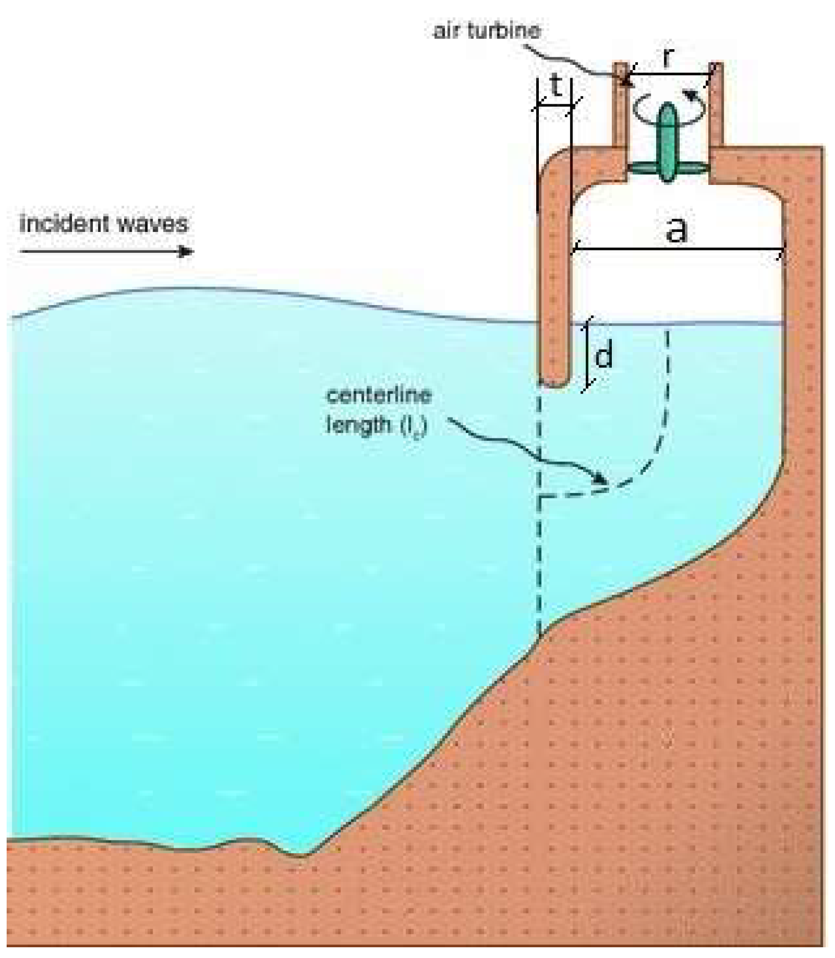
3.1.1. OWC Chamber
3.1.2. PTO Systems
Wells Turbines
Impulse Turbines
- -
- Axial-flow impulse turbines
- -
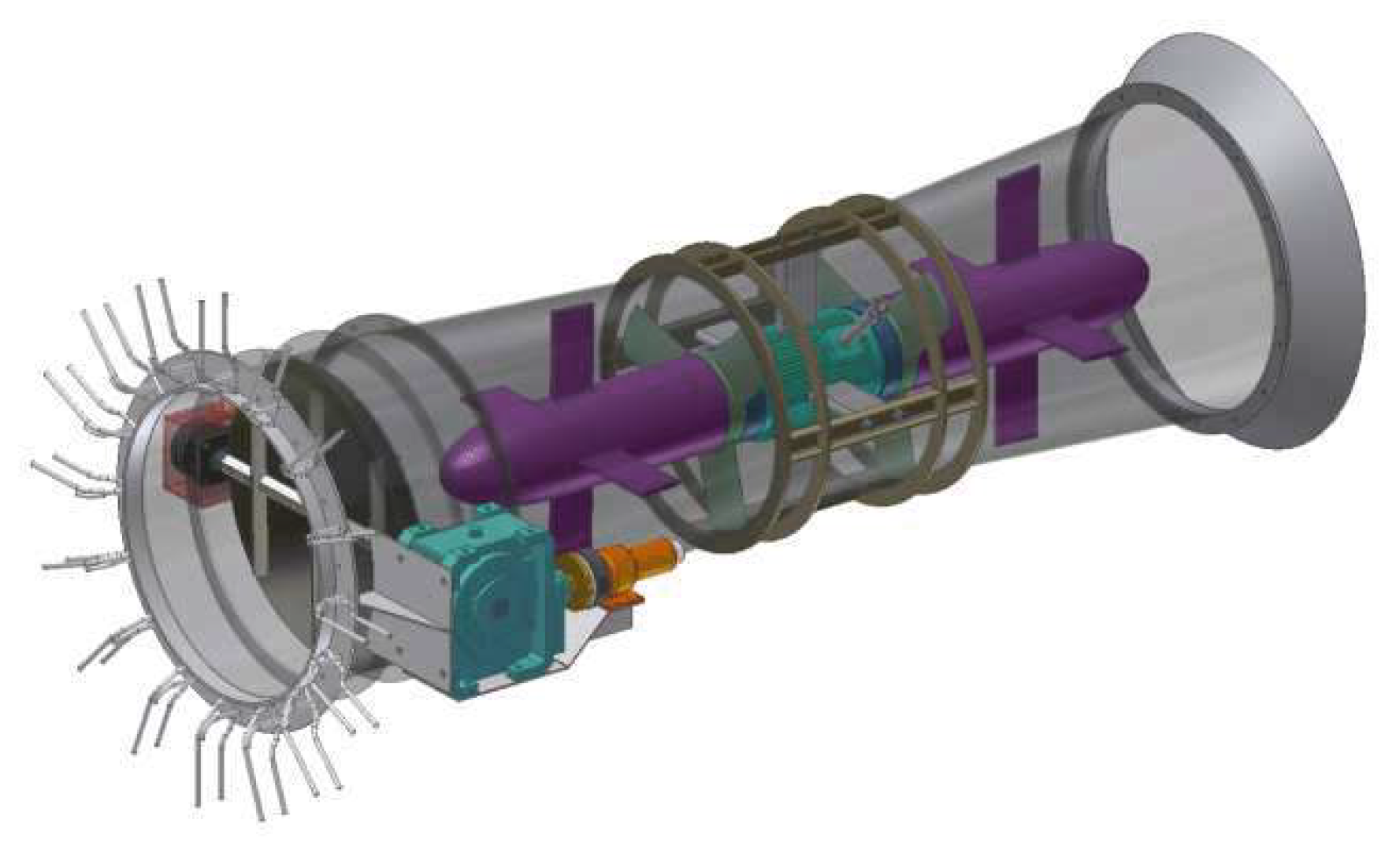
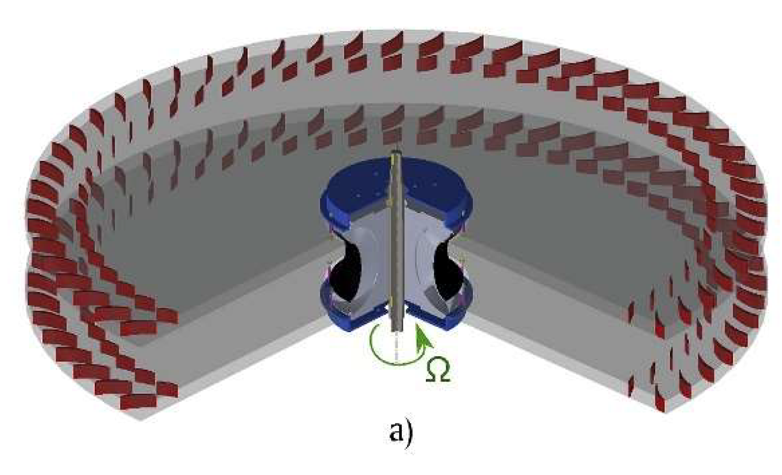
- Biradial impulse turbines (Figure 5)
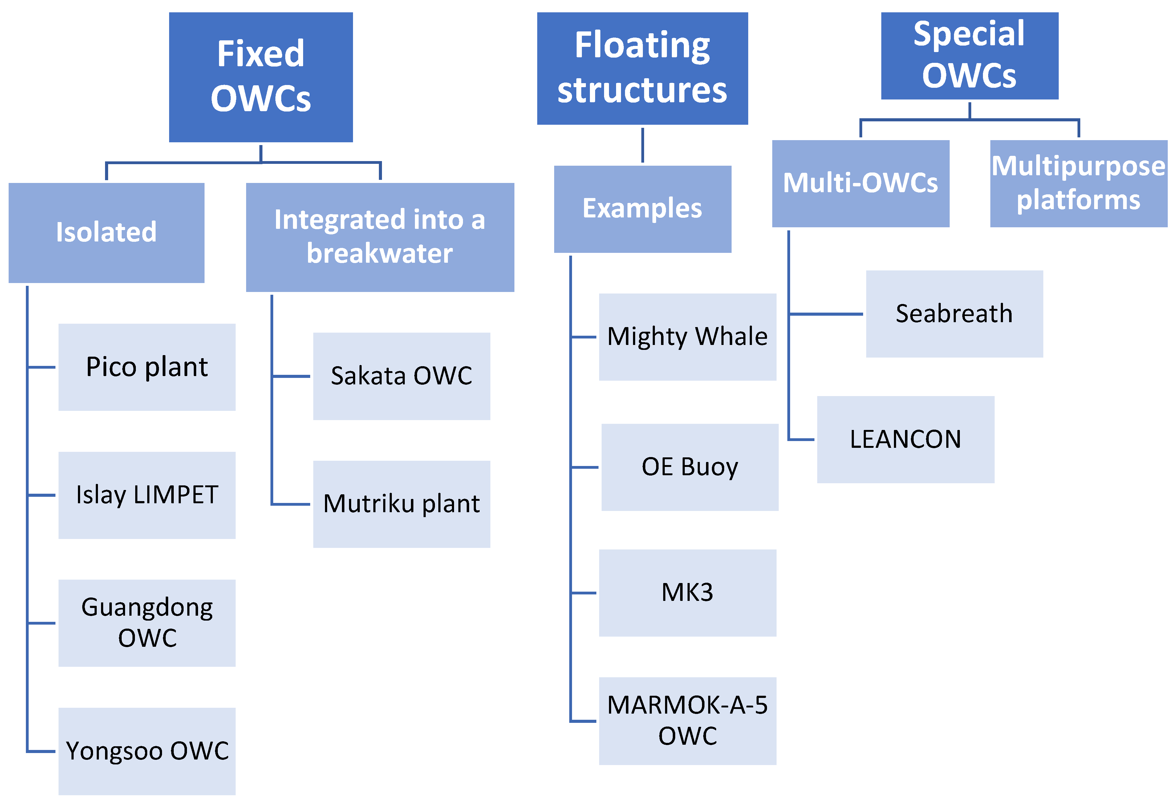
3.2. OWC Classification
- -
- Fixed structures
- ○
- Separate or isolated
- ▪
- ▪
- ○
- -
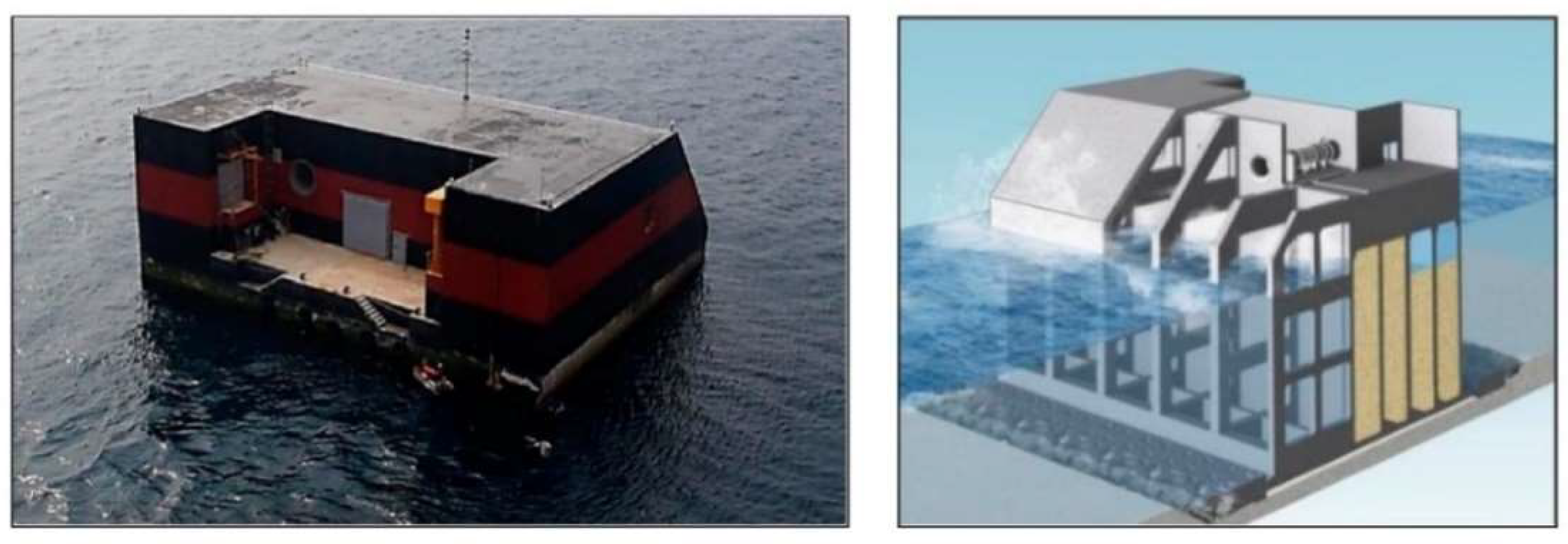
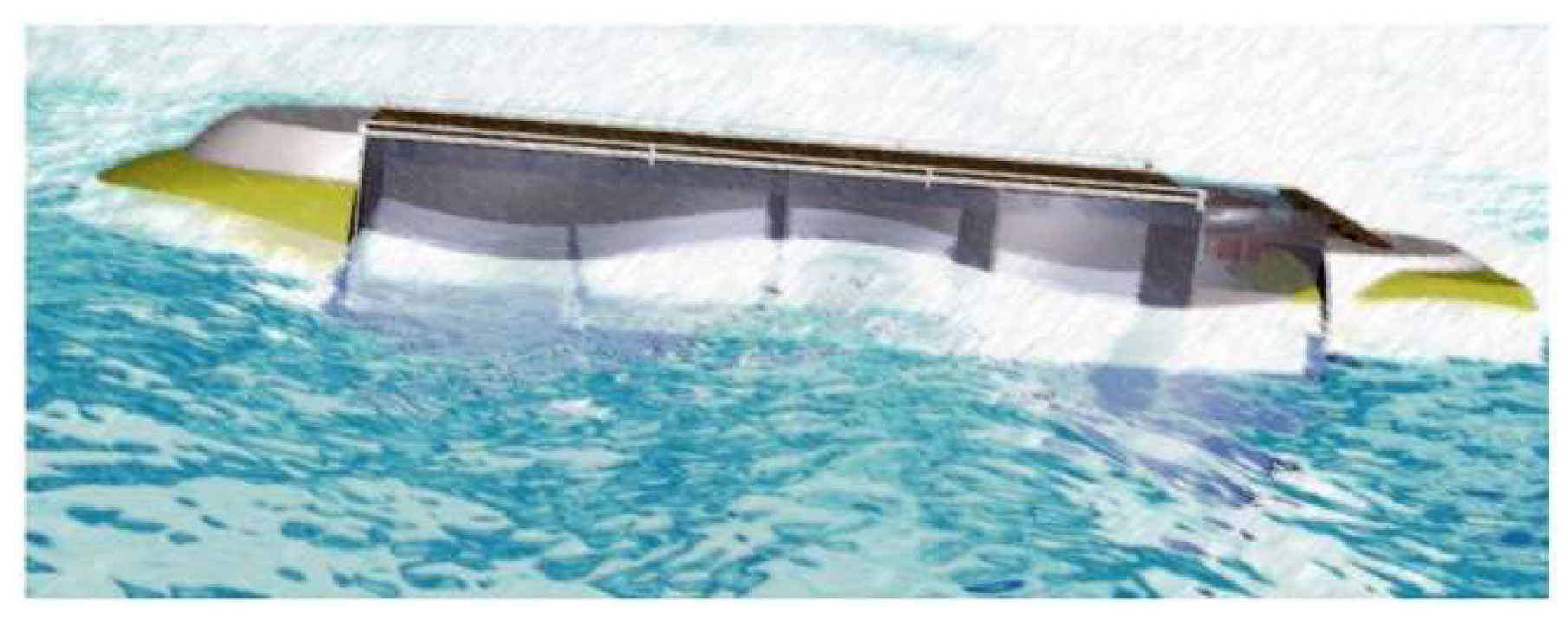
- Floating structures
- -
- Special OWCs
- ○
- Multi-OWCs
- ○
- Multipurpose platforms
- ○
- ○
- The BlueGrowthFarm, a project founded by the European Union that proposes a multifunctional platform with 10 MW wind turbines and several OWCs [41].
- ○
4. Influence of Wave Characteristics
4.1. Relative Water Depth d/L
4.2. Water Steepness H/L
4.3. Other Considerations
- ○
- The influence of H on the performance of the OWC becomes much more important near the breakpoint of the wave (at depth of 4 m in their study).
- ○
- For a better performance of the device, it is recommended to locate the OWC where it is not affected by bottom friction.
- ○
- The highest value of wave power does not necessarily correspond to the highest value of mechanical power extracted by the device. Only vertical velocity of the waves is useful and the wave power dissipated by the horizontal component of the velocity is wasted.
5. Influence of OWC Geometry
5.1. Geometric Parameters
- ○
- Effect of chamber width: The hydrodynamic efficiency increases as the chamber width increases for low frequencies, but it follows an opposite trend for high frequencies. In addition, the resonant frequency decreases as the chamber width increases, in line with Ning et al.’s results [44]).
- ○
- Effect of opening ratio: The hydrodynamic efficiency of the OWC increases with the opening ratio until reaching a maximum, and then decreases.
- ○
- Effect of relative chamber length: It is defined as the length of the chamber divided by the wavelength. As this ratio increases, the efficiency also does, until it reaches a maximum, and then decreases. It becomes more important with the period and height of the wave.
- ○
- Effect of submergence depth ratio: It is defined as the submersion depth of the OWC divided by the total depth. Its effect depends on the height and period of the wave.
- ○
- Effect of opening ratio: The results obtained were similar to the results obtained by Tsai et al. in 2018.
- ○
- Effect of nonlinearities: Nonlinear effects can significantly change the power absorption of an OWC.
- ○
- Effect of wall thickness: The efficient bandwidth of the OWC reduces as the thickness of the front wall increases.
- ○
- Effect of the bottom of the chamber: The efficiency band slightly shifts to longer periods as the bottom of the chamber becomes steeper. Therefore, for small periods it is better to use a flat bottom. The period in which resonance occurs is almost independent of the bottom geometrical configuration and it is mostly determined by the natural frequency of the water column.
5.2. U-Shaped, L-Shaped, and V-Shaped OWCs
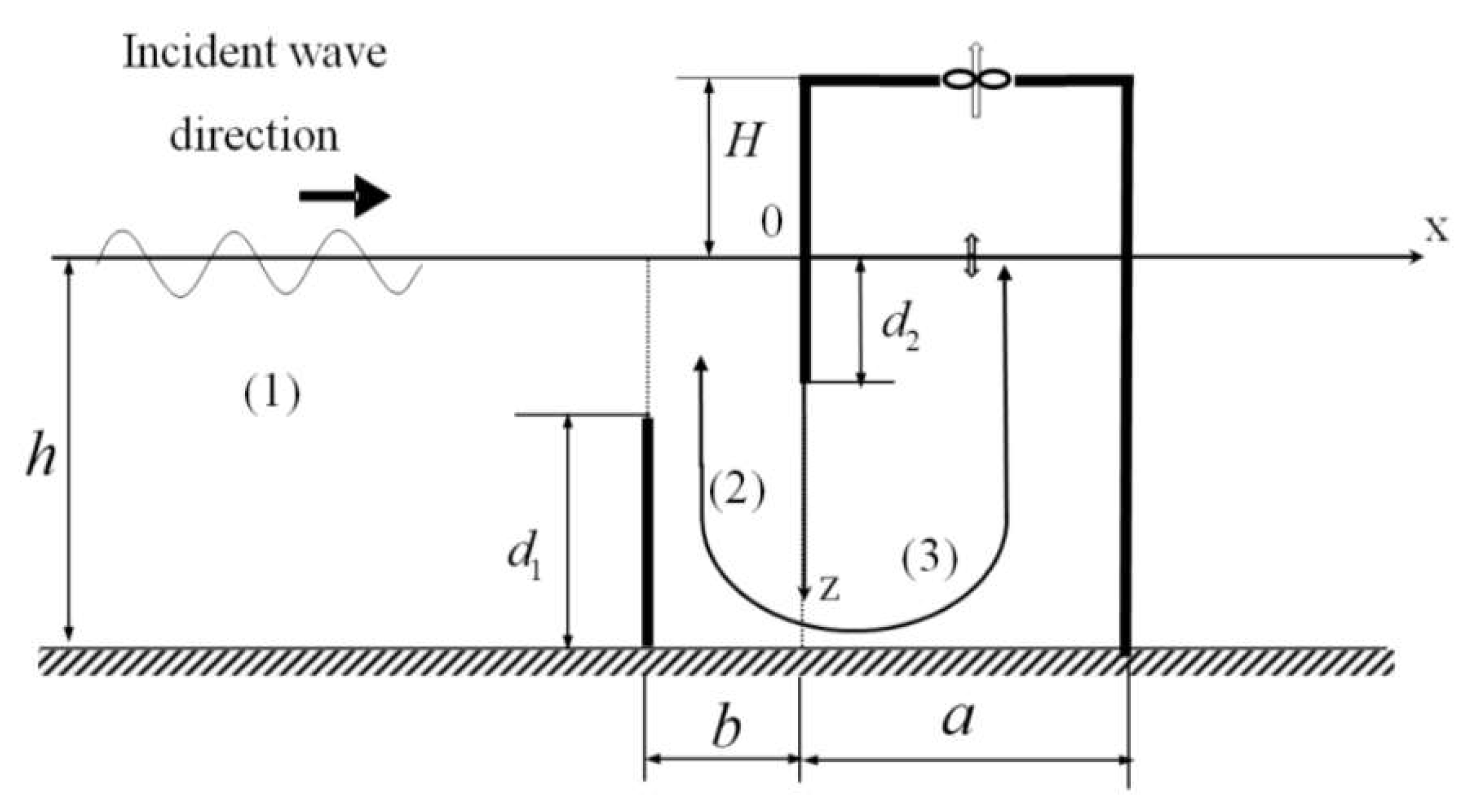
5.2.1. U-Shaped OWCs
- -
- The air pressure inside the chamber and, consequently, the hydrodynamic efficiency of the OWC increases with vertical duct height (d1 in Figure 15). In addition, the effect of the vertical duct height on the maximum pressure increases with kh increasing in relatively low frequency region.
- -
- The duct width (b in Figure 15) has also a great influence on the air pressure inside the chamber. A larger vertical duct width gives a larger hydrodynamic efficiency in a relatively low frequency domain. Moreover, the total hydrodynamic force exerted on the U-shaped water column almost increases linearly with the vertical duct width.
- -
- The wall width influences the maximum air pressure and the hydrodynamic efficiency too. The higher the wall width, the higher the maximum air pressure and efficiency.
5.2.2. L-Shaped OWCs
- -
- A wider vertical section of the chamber improves the performance of the L-shaped OWC, especially for periods different from the natural period of oscillation of the chamber.
- -
- The greater the height of the horizontal duct of the chamber, the higher the captured energy.
- -
- A shallower entrance enhances the efficiency of the OWC.
5.2.3. V-shaped OWCs
5.3. Use of Dual Chambers
- ○
- Efficiency: The results obtained in the models showed that the effective bandwidth of the dual chamber was about three times larger than in the single chamber. In addition, the peak efficiency was around 8% greater in the models (2018) and about 4% greater in the experiment setup (2019).
- ○
- Effect of submergence: A decrease in the outer chamber submergence causes an increase in both the maximum efficiency and the effective frequency bandwidth.
- ○
- Effect of chamber width: It increases the hydrodynamic performance of the device.
- ○
- Effect of the thickness of the shell: It was not very significant in the low-frequency domain, but in the high-frequency domain, thinner shells were better.
- ○
- Effect of the volume of the chamber: As it increases, the effective frequency bandwidth gets smaller, but the efficiency increases. An optimum chamber volume exists and it should be calculated for each case.
- ○
- Wave forces: They only studied the effect of horizontal forces because they are much bigger than vertical forces. The outer chamber is the chamber that suffers the highest wave loads, and these forces increase with frequency. However, forces in inner chamber increase with kh until they reach a peak, and then decrease.
- ○
- Effect of submergence: Horizontal forces in the outer chamber increase with its submergence. Increasing the curtain wall draft does not only reduce the power capture efficiency, as pointed out by Ning et al. [75,76], but also enlarges the forces on the OWC. Therefore, small curtain drafts are highly recommended.
- ○
- Effect of sub-chamber width ratio: Reducing the sub-chamber width ratio can help to reduce forces on the structure. Therefore, small sub-chamber width ratios are suggested.
5.4. Use of Arrays of OWCs
5.5. Influence of the Integration of a Breakwater in the OWC System
5.6. Use of Multifunctional Platforms
6. Influence of Air and Turbine Properties
6.1. Air Properties
6.2. Turbine Properties
- -
- The effect of the damping of the OWC CWR mainly depends on the chamber length and its relative water depth.
- -
- Near the resonant condition the effect of the optimal damping of the OWC is insensitive to the chamber geometry.
- -
- For other frequencies, higher values of optimal damping are found for decreasing chamber length.
- -
- The optimal damping is minimal for the resonant condition and increases for the remaining values of relative water depth.
- -
- Underdamping (damping coefficient lower than the optimal) reduces the device performance at a higher rate than overdamping.
7. Conclusions
- Wave characteristics
- ○
- Horizontal wave forces increase with the wave height and decrease with the wave length.
- ○
- The peak horizontal force is more than 2.5–3 times the peak vertical force.
- ○
- The maximum absorption of wave energy occurs when the relative water depth is around 0.131.
- ○
- An increase in wave steepness means an increase in the nonlinearities of the waves, which gives lower efficiencies of the OWC and larger forces.
- ○
- OWCs should be located where the bottom friction does not affect their performance.
- ○
- Neither the wave height nor the wave period may totally represent the nature of a wave; a design based on wave energy is recommended for OWCs.
- ○
- A large amount of wave energy does not always imply a good conversion efficiency.
- Geometric parameters
- ○
- Natural frequency of an OWC mainly depends on its chamber width and it is influenced by the front lip depth.
- ○
- Wider chambers should be used for longer waves and narrower chambers for shorter waves.
- ○
- For high values of the relative submergence of the lip wall, the CWR becomes narrower.
- ○
- Hydrodynamic efficiency increases as the breadth increases for low frequencies, but it follows an opposite trend for high frequencies.
- ○
- The CWR mainly depends on the bottom slope and it shifts to longer periods, as the bottom of the chamber becomes steeper. The CWR of the OWC reduces as the thickness of the front barrier wall is increased.
- ○
- As the chamber length–water depth ratio decreases, the period of maximum hydrodynamic efficiency becomes shorter.
- ○
- Circular bottom profile of the OWC is more efficient in terms of hydrodynamic performance.
- U-shaped, L-shaped, and V-shaped OWCs
- ○
- They usually perform better than conventional OWCs.
- ○
- Most studies point out the U-shaped OWC is the most efficient model. Its efficiency increases with the duct height and width and the wall width.
- Dual chambers
- ○
- They usually give higher peak efficiencies and a much larger CWR than single chambers.
- ○
- The outer shell draft should be smaller than the inner one.
- ○
- Thinner shells are recommended because they have a better performance in the high-frequency region. However, the design of a dual chamber needs a balance between strength and hydrodynamic performance.
- ○
- The seaside wall is the wall that suffers the highest forces. Therefore, it should be built with the best materials.
- ○
- A smaller sub-chamber width ratio is suggested.
- Breakwater-integrated OWCs
- ○
- These have better access for construction, and easier operation and maintenance.
- ○
- It helps to reduce wave reflection.
- ○
- The presence of the breakwater enhances the energy conversion performance of the OWC, but also amplifies the forces, which should be considered in the design process.
- ○
- It increases the CWR of the OWC.
- ○
- There are current research lines on new innovative systems.
- Multifunctional platforms
- ○
- These can reduce the investment, forces that act on the OWC and optimize its hydrodynamic efficiency.
- ○
- They are very convenient solutions.
- ○
- Research is currently being carried out in this field.
- Air and turbine properties
- ○
- Not considering air compressibility and humidity can lead to overestimating the hydrodynamic performance of the OWC.
- ○
- There is only one pair, chamber size, and corresponding damping that allows obtaining the maximum energy conversion for given wave conditions.
- ○
- The effect of the damping of the OWC CWR mainly depends on the chamber length and its relative water depth. At the resonant point it is insensitive to geometric characteristics and the value of the optimum damping is minimal.
- ○
- Overdamping is better than underdamping.
Author Contributions
Funding
Conflicts of Interest
References
- IPCC. Las Evaluaciones del IPCC de 1990 y 1992; Cambridge University Press: Cambridge, UK, 1992; p. 196. [Google Scholar]
- Falnes, J. A review of wave-energy extraction. Mar. Struct. 2007, 20, 185–201. [Google Scholar] [CrossRef]
- Czech, B.; Bauer, P. Wave Energy Converter Concepts, Design Challenge and Classification. IEEE Ind. Electron. Mag. 2012, 6, 4–16. [Google Scholar] [CrossRef]
- Centre for Renewable Energy Sources (CRES). Wave Energy Utilization in Europe; Centre for Renewable Energy Sources Publication Service: Athens, Greece, 2002; p. 32. ISBN 9608690714. [Google Scholar]
- Adebisi, N.; Balogun, A.-L.; Min, T.H.; Tella, A. Advances in estimating Sea Level Rise: A review of tide gauge, satellite altimetry and spatial data science approaches. Ocean. Coast. Manag. 2021, 208. [Google Scholar] [CrossRef]
- Heath, T.V. A review of oscillating water columns. Philos. Trans. R. Soc. 2012, 370, 235–245. [Google Scholar] [CrossRef] [PubMed] [Green Version]
- Bouali, B.; Larbi, S. Contribution to the geometry optimization of an oscillating water column wave energy converter. Energy Procedia 2013, 36, 565–573. [Google Scholar] [CrossRef] [Green Version]
- Malmo, O.; Reitan, A. Wave power absorption by an oscillating water column in a channel. J. Fluid Mech. 1985, 158, 153–175. [Google Scholar] [CrossRef]
- Raghunathan, S. The wells air turbine for wave energy conversion. Prog. Aerosp. Sci. 1995, 31, 335–386. [Google Scholar] [CrossRef]
- Todalshaug, J.H. Hydrodynamics of WECs. In Handbook of Ocean Wave Energy; Pecher, A., Kofoed, J.P., Eds.; Springer International Publishing: Berlin, Germany, 2017; pp. 139–158. [Google Scholar]
- Falcão, A.; Henriques, J. Oscillating-water-column wave energy converters and air turbines: A review. Renew. Energy 2016, 85, 1391–1424. [Google Scholar] [CrossRef]
- Brito-Melo, A.; Gato, L.M.C.; Sarmento, A. Analysis of Wells turbine design parameters by numerical simulation of the OWC performance. Ocean Eng. 2002, 29, 1463–1477. [Google Scholar] [CrossRef]
- TETHYS. Voith Hydro. Available online: https://tethys.pnnl.gov/organization/voith-hydro (accessed on 26 December 2021).
- Torre-Enciso, Y.; Ortubia, I.; Aguileta, L.I.L.D.; Marqués, J. Mutriku wave power plant: From the thinking out to the reality. In Proceedings of the 8th European Wave and Tidal Energy Conference (EWTEC 2009), Uppsala, Sweden, 10 September 2009. [Google Scholar]
- Têtu, A. Power Take-off systems for WECs. In Handbook of Ocean Wave Energy; Pecher, A., Kofoed, J.P., Eds.; Springer International Publishing: Berlin, Germany, 2017; pp. 203–220. [Google Scholar]
- Carrelhas, A.A.D.; Gato, L.M.C.; Henriques, J.C.C.; Falcão, A.F.O.; Varandas, J. Test results of a 30 kW self-rectifying biradial air turbine-generator prototype. Renew. Sustain. Energy Rev. 2019, 109, 187–198. [Google Scholar] [CrossRef]
- Henriques, J.C.C.; Portillo, J.C.C.; Gato, L.M.C.; Gomes, R.P.F.; Ferreira, D.N.; Falcão, A.F.O. Design of oscillating-water-column wave energy converters with an application to self-powered sensor buoys. Energy 2016, 112, 852–867. [Google Scholar] [CrossRef] [Green Version]
- Falcão, A.F.O.; Henriques, J.C.C.; Gato, L.M.C.; Gomes, R.P.F. Air turbine choice and optimization for floating oscillating-water-column wave energy converter. Ocean Eng. 2014, 75, 148–156. [Google Scholar] [CrossRef]
- Romolo, A.; Henriques, J.; Gato, L.M.C.; Malara, G.; Laface, V.; Gomes, R.; Portillo, J.C.C.; Falcão, A.; Arena, F. Power Take-Off Selection for a U-Shaped OWC Wave Energy Converter. Energy 2020, 215. [Google Scholar] [CrossRef]
- Moretti, G.; Malara, G.; Scialò, A.; Daniele, L.; Romolo, A.; Vertechy, R.; Fontana, M.; Arena, F. Modelling and field testing of a breakwater-integrated U-OWC wave energy converter with dielectric elastomer generator. Renew. Energy 2020, 146, 628–642. [Google Scholar] [CrossRef]
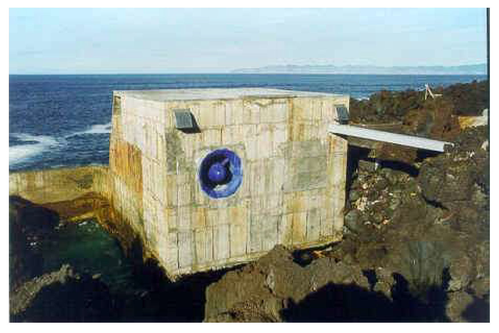
- Falcao, A. The shoreline OWC wave power plant at the Azores. In Proceedings of the 4th European Wave Energy Conference, Aalborg, Denmark, 4–6 December 2000; pp. 42–47. [Google Scholar]
- TETHYS. Pico Power Plant. Available online: https://tethys.pnnl.gov/project-sites/pico-power-plant (accessed on 24 December 2021).
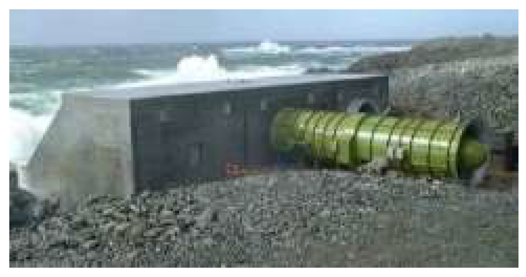
- Heath, T.V.; Whittaker, T.J.T.; Boake, C.B. The design, construction and operation of the LIMPET wave energy converter (Islay, Scotland). Renew. Energy 2016, 85, 49–50. [Google Scholar] [CrossRef]
- Sun, C.; Shang, J.; Luo, Z.; Lu, Z.; Wang, R. A Review of Wave Energy Extraction Technology. IOP Conf. Ser. Mater. Sci. Eng. 2018, 394, 042038. [Google Scholar] [CrossRef] [Green Version]
- Curto, D.; Franzitta, V.; Guercio, A. Sea Wave Energy. A Review of the Current Technologies and Perspectives. Energies 2021, 14, 6604. [Google Scholar] [CrossRef]
- Hsien, H.L.; Cheng-Han, C. Parametric Study for an Oscillating Water Column Wave Energy Conversion System Installed on a Breakwater. Energies 2020, 13, 1926. [Google Scholar] [CrossRef] [Green Version]
- Arena, F.; Romolo, A.; Malara, G.; Fiamma, V.; Laface, V. The first full operative U-OWC plants in the port of Civitavecchia. In Proceedings of the 36th International Conference on Ocean, Offshore and Arctic Engineering, Trondheim, Norway, 25–30 June 2017; p. V010T009A022. [Google Scholar]
- Bijun, W.; Meng, L.; Rukang, W.; Tianxiang, C.; Yunqiu, Z.; Yin, Y. BBDB wave energy conversion technology and perspective in China. Ocean Eng. 2018, 69, 281–291. [Google Scholar] [CrossRef]
- Falcão, A. Wave energy utilization: A review of the technologies. Renew. Sustain. Energy Rev. 2010, 14, 899–918. [Google Scholar] [CrossRef]
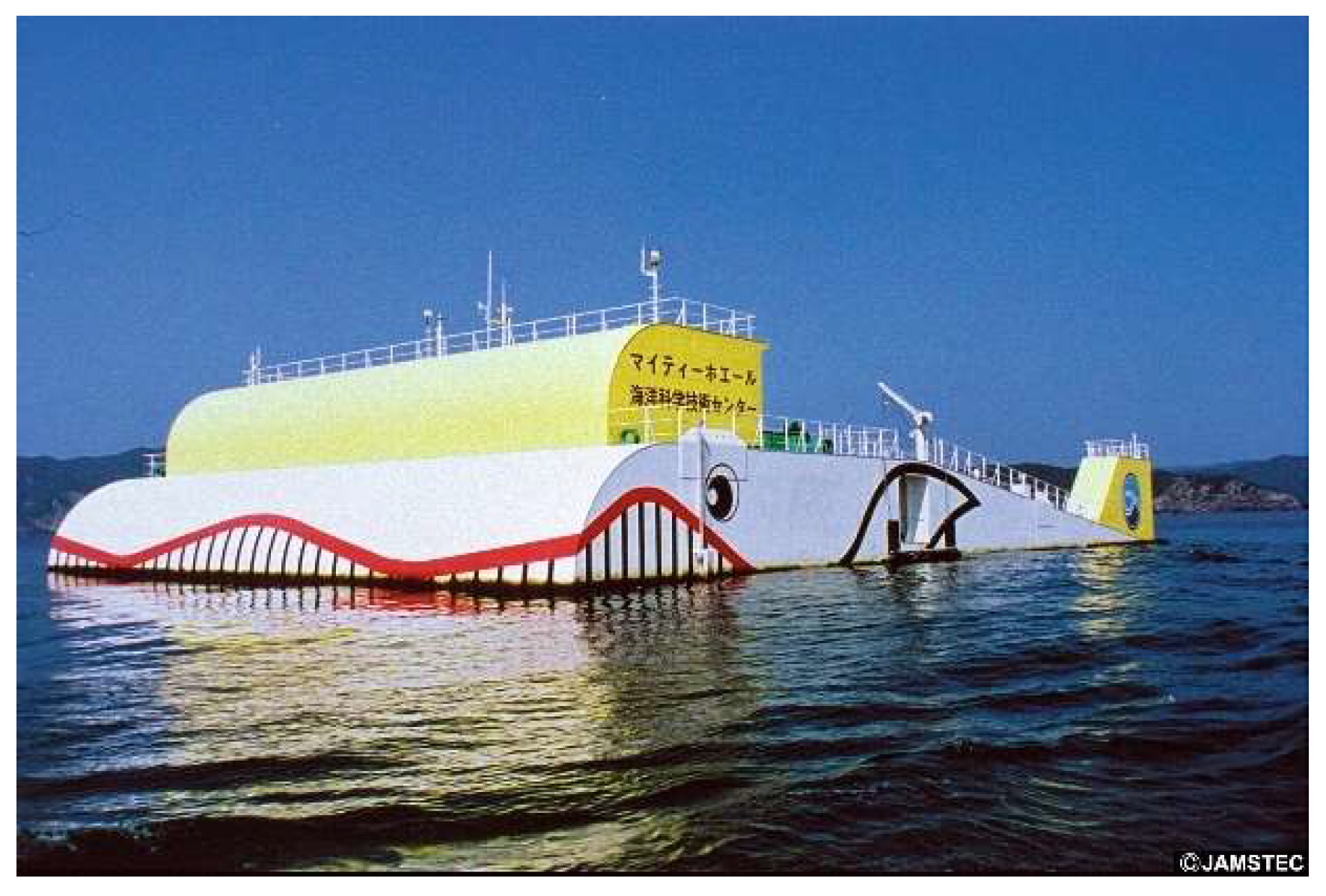
- JAMSTEC. JAMSTEC Gallery. Mighty Whale. Available online: http://www.jamstec.go.jp/gallery/j/research/system/images/system_002_l.jpg (accessed on 24 December 2021).
- McCormick, M. E Analysis of a Wave Energy Conversion Buoy. J. Hydronautics 2012, 8, 77–82. [Google Scholar] [CrossRef]
- Alcorn, R.; Bravette, A.; Healy, M.; Lewis, A. FP7 EU funded CORES wave energy project: A coordinators’ perspective on the Galway Bay sea trials. Underw. Technol. 2014, 32, 51–59. [Google Scholar] [CrossRef] [Green Version]
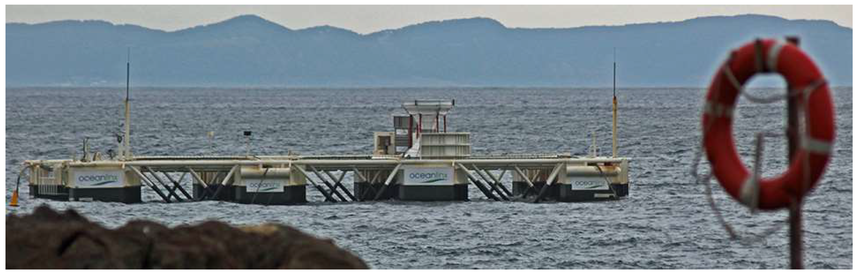
- TETHYS. Oceanlinx MK3. Available online: https://tethys.pnnl.gov/project-sites/oceanlinx-mk3 (accessed on 24 December 2021).
- Zabala, I.; Henriques, J.; Gomez, A.; Falcão, A.; Amezaga, A.; Gomes, R.; Gato, L.M.C. Assessment of a spar buoy oscillating-water-column wave energy converter including a fully dynamic model. In Proceedings of the 12th European Wave and Tidal Energy Conference, Cork, Ireland, 27 August–1 September 2017. [Google Scholar]
- Henriques, J. The (Integrated) Development of the Spar-Buoy OWC Wave Energy Converter at IST. Master in Renewable Energy in the Marine Environment. 2021. Available online: https://renovables-eurorregion.com/wp-content/uploads/MORE__The_integrated_development_spar_buoy_OWC_20210622.pdf (accessed on 30 December 2021).
- IDOM. Prototipo WEC MARMOK A-5. Available online: https://www.idom.com/en/project/wave-energy-converter-prototype-marmok-a-5-2/ (accessed on 30 December 2021).
- Martinelli, L.; Pezzutto, P.; Ruol, P. Experimentally Based Model to Size the Geometry of a New OWC Device, with Reference to the Mediterranean Sea Wave Environment. Energies 2013, 6, 4696–4720. [Google Scholar] [CrossRef]
- Sarmiento, J.; Iturrioz, A.; Ayllón, V.; Guanche, R.; Losada, I.J. Experimental modelling of a multi-use floating platform for wave and wind energy harvesting. Ocean Eng. 2019, 173, 761–773. [Google Scholar] [CrossRef]
- Perez-Collazo, C.; Pemberton, R.; Greaves, D.; Iglesias, G. Monopile-mounted wave energy converter for a hybrid wind-wave system. Energy Convers. Manag. 2019, 199, 111971. [Google Scholar] [CrossRef]
- Principle Power. WindFloat. Available online: https://www.principlepower.com/windfloat (accessed on 30 December 2021).
- Ruzzo, C.; Muggiasca, S.; Malara, G.; Taruffi, F.; Belloli, M.; Collu, M.; Li, L.; Brizzi, G.; Arena, F. Scaling strategies for multi-purpose floating structures physical modeling: State of art and new perspectives. Appl. Ocean. Res. 2021, 108, 102487. [Google Scholar] [CrossRef]
- Pérez-Collazo, C.; Greaves, D.; Iglesias, G. Proof of concept of a novel hybrid wind-wave energy converter. In Proceedings of the 37th International Conference on Ocean, Offshore and Arctic Engineering, Madrid, Spain, 17–22 June 2018; p. V010T009A019. [Google Scholar]
- Jasron, J.; Soeparmani, S.; Yuliati, L.; Darmadi, D. Experimental Study on the Effect of Ocean Wave Characteristics on Air Pressure in Oscillating Water Column Device. IOP Conf. Ser. Mater. Sci. Eng. 2019, 494. [Google Scholar] [CrossRef]
- Ning, D.Z.; Wang, R.Q.; Zou, Q.P.; Teng, B. An experimental investigation of hydrodynamics of a fixed OWC wave energy converter. Appl. Energy 2016, 168, 636–648. [Google Scholar] [CrossRef]
- Rezanejad, K.; Guedes Soares, C.; Lopez, I.; Carballo, R. Experimental and numerical investigation of the hydrodynamic performance of an oscillating water column wave energy converter. Renew. Energy 2017, 106, 1–16. [Google Scholar] [CrossRef]
- Huang, Z.; Xu, C.; Huang, S. A CFD simulation of wave loads on a pile-type oscillating-water-column device. J. Hydrodyn. 2019, 31, 41–49. [Google Scholar] [CrossRef]
- Sundar, V.; Sannasiraj, S.A.; Ashlin, J.; Jegatheeswaran, B. An experimental study of an oscillating water column with different bottom configuration. In Proceedings of the 3rd IAHR Europe Congress, Porto, Portugal, 14–16 April 2014. [Google Scholar]
- Ashlin, J.; Sannasiraj, S.; Sundar, V. Wave forces on an Oscillating Water Column Device. Procedia Eng. 2015, 116, 1019–1026. [Google Scholar] [CrossRef] [Green Version]
- Thiruvenkatasamy, K.; Neelamani, S. On the efficiency of wave energy caisson in array. Appl. Ocean. Res. 1997, 19, 61–72. [Google Scholar] [CrossRef]
- Zhou, Y.; Ning, D.; Shi, W.; Johanning, L.; Liang, D. Hydrodynamic investigation on an OWC wave energy converter integrated into an offshore wind turbine monopile. Coast. Eng. 2020, 162, 103731. [Google Scholar] [CrossRef]
- D’Aquino, C.; Cataldo, C.; Casagrande, L. Evaluation of the energy extraction of a small-scale wave energy converter. Braz. J. Water Resour. 2019, 24, e13. [Google Scholar] [CrossRef] [Green Version]
- Zheng, W. Experimental Research and Parameters Optimization of a Prototype OWC Wave Power Device; American Society of Civil Engineers: Reston, VA, USA, 1989; pp. 43–50. [Google Scholar]
- Evans, D.V.; Porter, R. Hydrodynamic characteristics of an oscillating water column device. Appl. Ocean. Res. 1995, 17, 155–164. [Google Scholar] [CrossRef]
- Morris-Thomas, M.T.; Irvin, R.J.; Thiagarajan, K.P. An Investigation into the Hydrodynamic Efficiency of an Oscillating Water Column. J. Offshore Mech. Arct. Eng. 2007, 129, 273–278. [Google Scholar] [CrossRef]
- Simonetti, I.; Cappietti, L.; Elsafti, H.; Oumeraci, H. Optimization of the geometry and the turbine induced damping for fixed detached and asymmetric OWC devices: A numerical study. Energy 2017, 139, 1197–1209. [Google Scholar] [CrossRef]
- Tsai, C.; Chun-Han, K.; Ying-Chi, C. Investigation on Performance of a Modified Breakwater-Integrated OWC Wave Energy Converter. Sustainability 2018, 10, 643. [Google Scholar] [CrossRef] [Green Version]
- Medina, A.; Blanco, J.M.; Silva, R.; Izquierdo, U. The Influence of the Chamber Configuration on the Hydrodynamic Efficiency of Oscillating Water Column Devices. J. Mar. Sci. Eng. 2020, 8, 751. [Google Scholar] [CrossRef]
- Koley, S.; Trivedi, K. Mathematical modeling of oscillating water column wave energy converter devices over the undulated sea bed. Eng. Anal. Bound. Elem. 2020, 117, 26–40. [Google Scholar] [CrossRef]
- Rezanejad, K.; Bhattacharjee, J.; Guedes Soares, C. Stepped sea bottom effects on the efficiency of nearshore oscillating water column device. Ocean Eng. 2013, 70, 25–38. [Google Scholar] [CrossRef]
- Chen, J.; Wen, H.; Wang, Y.; Wang, G. A correlation study of optimal chamber width with the relative front wall draught of onshore OWC device. Energy 2021, 225, 120307. [Google Scholar] [CrossRef]
- Guo, B.; Ning, D.; Wang, R.; Ding, B. Hydrodynamics of an oscillating water column WEC—Breakwater integrated system with a pitching front-wall. Renew. Energy 2021, 176, 67–80. [Google Scholar] [CrossRef]
- Fox, B.N.; Gomes, R.P.F.; Gato, L.M.C. Analysis of oscillating-water-column wave energy converter configurations for integration into caisson breakwaters. Appl. Energy 2021, 295. [Google Scholar] [CrossRef]
- Boccotti, P. Comparison between a U-OWC and a conventional OWC. Ocean Eng. 2007, 34, 799–805. [Google Scholar] [CrossRef]
- Malara, G.; Arena, F. Analytical modelling of an U-Oscillating Water Column and performance in random waves. Renew. Energy 2013, 60, 116–126. [Google Scholar] [CrossRef]
- Vyzikas, T.; Deshoulieres, S.; Barton, M.; Giroux, O.; Greaves, D.; Simmonds, D. Experimental investigation of different geometries of fixed oscillating water column devices. Renew. Energy 2017, 104, 248–258. [Google Scholar] [CrossRef] [Green Version]
- Lopez, I.; Carballo, R.; Fouz, D.M.; Iglesias, G. Design Selection and Geometry in OWC Wave Energy Converters for Performance. Energies 2021, 14, 1707. [Google Scholar] [CrossRef]
- Ning, D.; Guo, B.; Wang, R.; Vyzikas, T.; Greaves, D. Geometrical investigation of a U-shaped oscillating water column wave energy device. Appl. Ocean. Res. 2020, 97. [Google Scholar] [CrossRef]
- George, A.; Cho, I.-H.; Kim, M.-H. Optimal Design of a U-Shaped Oscillating Water Column Device Using an Artificial Neural Network Model. Processes 2021, 9, 1338. [Google Scholar] [CrossRef]
- Rezanejad, K.; Souto-Iglesias, A.; Guedes Soares, C. Experimental investigation on the hydrodynamic performance of an L-shaped duct oscillating water column wave energy converter. Ocean Eng. 2019, 173, 388–398. [Google Scholar] [CrossRef]
- Samak, M.M.; Elgamal, H.; Nagib Elmekawy, A.M. The contribution of L-shaped front wall in the improvement of the oscillating water column wave energy converter performance. Energy 2021, 226, 120421. [Google Scholar] [CrossRef]
- Kofoed, J.; Frigaard, P. Hydraulic Evaluation of the LEANCON Wave Energy Converter; DCE Technical Reports No. 45; Department of Civil Engineering, Aalborg University: Aalborg, Denmark, 2008. [Google Scholar]
- Kelly, T.; Dooley, T.; Campbell, J.; Ringwood, J.V. Comparison of the Experimental and Numerical Results of Modelling a 32-Oscillating Water Column (OWC), V-Shaped Floating Wave Energy Converter. Energies 2013, 6, 4045–4077. [Google Scholar] [CrossRef] [Green Version]
- Rezanejad, K.; Bhattacharjee, J.; Soares, C.G. Analytical and numerical study of dual chamber oscillating water columns on stepped bottom. Renew. Energy 2015, 75, 272–282. [Google Scholar] [CrossRef]
- Elhanafi, A.; Macfarlane, G.; Ning, D. Hydrodynamic performance of single-chamber and dual-chamber offshore-stationary Oscillating Water Column devices using CFD. Appl. Energy 2018, 228, 82–96. [Google Scholar] [CrossRef]
- Ning, D.; Zhou, Y.; Mayon, R.; Johanning, L. Experimental investigation on the hydrodynamic performance of a cylindrical dual-chamber Oscillating Water Column device. Appl. Energy 2020, 260. [Google Scholar] [CrossRef]
- Zhao, X.L.; Ning, D.Z.; Zou, Q.P.; Qiao, D.S.; Cai, S.Q. Hybrid floating breakwater-WEC system: A review. Ocean Eng. 2019, 186, 106–126. [Google Scholar] [CrossRef]
- Ning, D.; Zhou, Y.; Zhang, C. Hydrodynamic modeling of a novel dual-chamber OWC wave energy converter. Ocean. Res. 2018, 78, 180–191. [Google Scholar] [CrossRef]
- Wang, R.; Ning, D.; Zou, Q. Wave loads on a land-based dual-chamber Oscillating Water Column wave energy device. Coast. Eng. 2020, 160. [Google Scholar] [CrossRef]
- Hsieh, M.F.; Dorrel, D.G.; Lin, C.C. A Multichamber Oscillating Water Column using Cascaded Savonius Turbines. IEEE Trans. Ind. Appl. 2010, 46, 2372–2380. [Google Scholar] [CrossRef]
- Tseng, R.S.; Wu, R.H.; Huang, C.C. Model study of a shoreline wave-power system. Ocean Eng. 2000, 27, 801–821. [Google Scholar] [CrossRef]
- Atan, R.; Finnegan, W.; Nash, S.; Goggins, J. The effect of arrays of wave energy converters on the nearshore wave climate. Ocean Eng. 2019, 172, 373–384. [Google Scholar] [CrossRef]
- Jasron, J.; Soeparmani, S.; Yuliati, L.; Darmadi, D. Comparison of the performance of oscillating water column devices based on arrangements of water columns. J. Mech. Eng. Sci. 2020, 14, 7082–7093. [Google Scholar] [CrossRef]
- Zhao, X.L.; Ning, D.Z.; Liang, D.F. Experimental investigation on hydrodynamic performance of a breakwater integrated WEC system. Ocean Eng. 2019, 171, 25–31. [Google Scholar] [CrossRef]
- Wan, C.; Yang, C.; Fang, Q.; You, Z.; Geng, J.; Wang, Y. Hydrodynamic Investigation of a Dual-Cylindrical OWC Wave Energy Converter Integrated into a Fixed Caisson Breakwater. Energies 2020, 13, 896. [Google Scholar] [CrossRef] [Green Version]
- Viviano, A.; Naty, S.; Foti, E.; Bruce, T.; Allsop, W.; Vicinanza, D. Large-scale experiments on the behaviour of a generalised Oscillating Water Column under random waves. Renew. Energy 2016, 29, 875–887. [Google Scholar] [CrossRef] [Green Version]
- Reabroy, R.; Zheng, X.; Zhang, L.; Zang, J.; Yuan, Z.; Liu, M.; Sun, K.; Tiaple, Y. Hydrodynamic response and power efficiency analysis of heaving wave energy converter integrated with breakwater. Energy Convers. Manag. 2019, 195, 1174–1186. [Google Scholar] [CrossRef]
- Howe, D.; Nader, J.-R. OWC WEC integrated within a breakwater versus isolated: Experimental and numerical theoretical study. Int. J. Mar. Energy 2017, 20, 165–182. [Google Scholar] [CrossRef]
- Howe, D.; Nader, J.-R.; Macfarlane, G. Experimental investigation of multiple Oscillating Water Column Wave Energy Converters integrated in a floating breakwater: Energy extraction performance. Appl. Ocean. Res. 2020, 97, 102086. [Google Scholar] [CrossRef]
- Konispoliatis, D. Performance of an Array of Oscillating Water Column Devices in Front of a Fixed Vertical Breakwater. J. Mar. Sci. Eng. 2020, 8, 912. [Google Scholar] [CrossRef]
- Konispoliatis, D.; Mavrakos, S. Hydrodynamic Efficiency of a Wave Energy Converter in Front of an Orthogonal Breakwater. J. Mar. Sci. Eng. 2021, 9, 94. [Google Scholar] [CrossRef]
- Wang, C.; Zhang, Y. Hydrodynamic performance of an offshore Oscillating Water Column device mounted over an immersed horizontal plate: A numerical study. Energy 2021, 222, 119964. [Google Scholar] [CrossRef]
- Wang, C.; Ma, T.; Zhang, Y. Semi-analytical study on an integrated-system with separated heaving OWC and breakwater: Structure size optimization and gap resonance utilization. Ocean Eng. 2022, 245, 110319. [Google Scholar] [CrossRef]
- Medina-Lopez, E.; Borthwick, A.G.L.; Moñino, A. Analytical and numerical simulations of an oscillating water column with humidity in the air chamber. J. Clean. Prod. 2019, 238, 117898. [Google Scholar] [CrossRef]
- Moñino, A.; Quirós, C.; Mengíbar, F.; Medina-Lopez, E.; Clavero, M. Thermodynamics of the OWC chamber: Experimental turbine performance under stationary flow. Renew. Energy 2020, 155, 317–329. [Google Scholar] [CrossRef]
- Thakker, A.; Dhanasekaran, T.S.; Takao, M.; Setoguchi, T. Effects of compressibility on the performance of a wave-energy conversion device with an impulse turbine using a numerical simulation technique. Int. J. Rotating Mach. 2003, 9, 443–450. [Google Scholar] [CrossRef] [Green Version]
- Teixeira, P.R.F.; Davyt, D.P.; Didier, E.; Ramalhais, R. Numerical simulation of an oscillating water column device using a code based on Navier-Stokes equations. Energy 2013, 61, 513–530. [Google Scholar] [CrossRef]
- Goncalves, R.A.A.C.; Teixeira, P.R.F.; Didier, E.; Torres, F.R. Numerical analysis of the influence of air compressibility effects on an oscillating water column wave energy converter chamber. Renew. Energy 2020, 153, 1183–1193. [Google Scholar] [CrossRef]
- Pereiras, B.; Lopez, I.; Castro, F.; Iglesias, G. Non-dimensional analysis for matching an impulse turbine to an OWC (oscillating water column) with an optimum energy transfer. Energy 2015, 87, 481–489. [Google Scholar] [CrossRef]
- López, I.; Pereiras, B.; Castro, F.; Iglesias, G. Optimisation of turbine-induced damping for an OWC wave energy converter using a RANS–VOF numerical model. Appl. Energy 2014, 127, 105–114. [Google Scholar] [CrossRef]
- López, I.; Pereiras, B.; Castro, F.; Iglesias, G. Holistic performance analysis and turbine-induced damping for an OWC wave energy converter. Renew. Energy 2016, 85, 1155–1163. [Google Scholar] [CrossRef]
- Bouali, B.; Larbi, S. Sequential optimization and performance prediction of an oscillating water column wave energy converter. Ocean Eng. 2017, 131, 162–173. [Google Scholar] [CrossRef]


| Forces | Efficiency | Comments | |
|---|---|---|---|
| Wave period T | Less sensitive | - | |
| Wave Height H | Positive relationship | Positive relationship | More important near the breaking point |
| Wave Length L | Negative relationship | Positive relationship | Better to not be affected by bottom friction |
| Wave Steepness H/L | Positive relationship | Negative relationship | Increases nonlinearities |
| Relative depth d/L | Increases until 0.16 and decreases | Maximum around 0.131 | |
| Comments | Peak horizontal force is 2.5-3 times the peak vertical force | Only vertical velocity is useful, the horizontal component is wasted |
| Efficiency | Frequency Bandwidth | Resonant Frequency | Comments | |
|---|---|---|---|---|
| Relative Chamber Width (Divided by water depth) | Positive for low frequencies and long waves Negative for high frequencies and short waves | Negative Relationship | Positive relationship for long waves Negative relationship for short waves | Optimum value 0.8–1 |
| Relative Chamber Length (Divided by wavelength) | Follows an U-inverted shape | Follows a concave parabolic shape | Negative relationship | More important for great values of periods and heights |
| Relative submergence (Divided by water depth) | Better behavior at resonant frequency for low values | Negative relationship | Negative relationship | Optimum value 0.3–80.44 depends on the height and period of the wave |
| Opening ratio | Follows an U-inverted shape | - | - | Significantly influenced by wave height |
| Thickness of the wall | Indifferent | Negative relationship | - | - |
| Wave Forces | Efficiency | Frequency Bandwidth | Resonant Frequency | Comments | |
|---|---|---|---|---|---|
| Inner chamber draft | Positive relationship | Negative relationship | Positive relationship | Negative relationship | Must be bigger than the outer draft |
| Outer chamber draft | Positive relationship | Negative relationship | Negative relationship | Negative relationship | Must be smaller than the inner draft |
| Chamber breadth | - | Positive relationship | - | - | |
| Thickness of the wall | - | Negative relationship for high frequencies | - | - | - |
| Volume of the chamber | Negative relationship | Positive relationship | Negative relationship | - | - |
Publisher’s Note: MDPI stays neutral with regard to jurisdictional claims in published maps and institutional affiliations. |
© 2022 by the authors. Licensee MDPI, Basel, Switzerland. This article is an open access article distributed under the terms and conditions of the Creative Commons Attribution (CC BY) license (https://creativecommons.org/licenses/by/4.0/).
Share and Cite
Portillo Juan, N.; Negro Valdecantos, V.; Esteban, M.D.; López Gutiérrez, J.S. Review of the Influence of Oceanographic and Geometric Parameters on Oscillating Water Columns. J. Mar. Sci. Eng. 2022, 10, 226. https://doi.org/10.3390/jmse10020226
Portillo Juan N, Negro Valdecantos V, Esteban MD, López Gutiérrez JS. Review of the Influence of Oceanographic and Geometric Parameters on Oscillating Water Columns. Journal of Marine Science and Engineering. 2022; 10(2):226. https://doi.org/10.3390/jmse10020226
Chicago/Turabian StylePortillo Juan, Nerea, Vicente Negro Valdecantos, M. Dolores Esteban, and José Santos López Gutiérrez. 2022. "Review of the Influence of Oceanographic and Geometric Parameters on Oscillating Water Columns" Journal of Marine Science and Engineering 10, no. 2: 226. https://doi.org/10.3390/jmse10020226