1. Introduction
On the drill floor of a mobile offshore drilling facility, many types of large and heavy equipment move at the same time, and they often work together. In general, a deep-sea offshore drilling rig has two well centers, each with two operators working together in a drilling control station. Each operator can utilize the equipment individually. Many machines perform a given task while moving along the railed paths. Therefore, even when working manually, several devices can move at the same time. Movements usually occur in a simple horizontal or vertical direction, but some equipment involves rotation. If a collision occurs, fatalities may occur, and property may be damaged due to the nature of heavy machines on the drilling rig. This includes loss due to damaged equipment, personal injuries, and the resulting delay in the process. In order to prevent these problems, a system is installed that can prevent collisions by forcibly stopping the equipment when the equipment approaches within a certain distance. This usually is referred to as an anti-collision system (ACS).
Simulation technology is used to experience the operation of drilling rigs in advance or to improve the drilling process. It is used for checking the logic related to the actual control of the equipment and for applying the logic directly to the actual process. The simulator considers the specifications of the equipment installed on the drilling vessel. In modern times, it has expanded from a simple simulator to a digital twin. The concept of digital twins was first introduced by NASA and DARPA’s Apollo project [
1]. Since it first appeared in NASA’s draft in 2010 [
2], the name “digital twin” has been used extensively in many industrial sectors [
3]. Digital twins generally are defined as ‘virtual twins operating logically in a computer with respect to physical objects operating in real time’. In this case, the physical object is a concept that includes all products, parts, processes, and systems, depending on the object that is being utilized. Tao et al. summarized the history and issues such as key components, current development, and application in industry [
4].
As the safety requirements increase over time, the concept of digital twins can be applied to analyze in advance the likely effects and problems that could occur when a new system is applied as well as analyze any accidents that actually occur. The methods of designing digital twins can be divided into two main categories [
5,
6]. The first category is data-based, and the second one is system-based. A data-based digital twin means to structure the data of a physical object according to some criteria, and a system-based digital twin is a method that focuses on real objects. In the case of the ACS, a digital twin design method for a physical object is a better choice because modelling is performed to imitate real equipment and software (SW). The main objective of this paper is to apply digital twin technology to visualize the ACS of an offshore drilling system and to analyze situations about events related to collisions.
There are two main reasons for using the concept of digital twins to improve the ACS. First, it should be possible to analyze past data while they are being replayed. Second, for system improvement and optimization, updating the ACS should be possible irrespective of whether the actual system is operating. In general, information related to incidents that involve safety is analyzed using the visual information of the closed-circuit television (CCTV), and/or the stored data of corresponding machines are recycled using an ACS-related system. However, the CCTV system has blind spots due to the complicated working environment and the limited viewing angles. In the case of the method using stored data, it is difficult to analyze raw data, and separate SW is often required. To resolve these problems, the development direction can be set by dividing this into three areas by function, i.e., visualization, reflecting floater’s movement, and generating virtual input. In terms of visualization, the concept of digital twins can be utilized for analyzing accidents and improving the system. While reconstructing the environment in which the accident occurred, it is necessary to display as much information as possible to enable a comprehensive investigation. To visualize past data, it should be possible to store real-time information and reproduce a specific point in time. Most of the deep-sea drilling units are drill ships or semi-submersible rigs, and this means that the motions of the floaters have six degrees of freedom. The digital twin of the ACS must be able to reflect the movement of the floating body. In order to apply and optimize a new method or system, it must be possible to create a virtual input and observe the system’s response, and it must be possible to apply new changes directly to the existing system.
In order to construct a system model-based digital twin, all the technical information necessary for the visualization of the collision avoidance system must be organized.
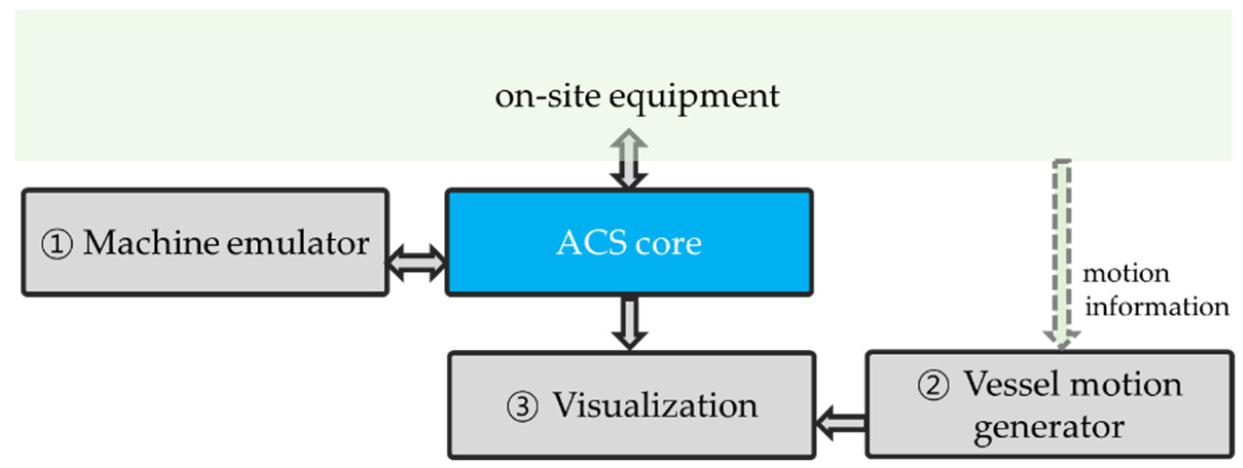
Figure 1 shows the overall structure that includes the aforementioned three development directions. The ACS core is a central module that monitors the possibility of a collision involving equipment on the drill floor, and it stops the operation of the equipment when an event occurs that satisfies the specified conditions. After receiving information about the movement of equipment from the ACS emulator, collisions between equipment are checked by the core. The result is sent to the visualization module so that the moving status of the equipment and the collision status can be observed.
A machine emulator is a device that can operate drilling-related equipment. It is a module that can manipulate real equipment and can create motion for virtual equipment that appears on the screen of the digital twin. The input device of the simulator can move drilling equipment and change parameters related to the ACS. The digital twin system should allow changes made in the virtual twin to be applied directly to the running object in real time. Therefore, it should be possible to optimize parameters by operating a virtual system in a condition where the real system is being operated. For this purpose, an input system is required that is separate from the operating devices in charge of controlling the actual system, and this must be implemented in the ACS simulator.
The vessel motion generator is a device that generates the motion of a floating body and sends it to the visualization module. The module can receive and transmit the motion of an actual floating body, or it can generate a virtual motion. This module is included for the offshore environment, which is one of the most important factors in relation to the working environment of offshore drilling units. It expresses the posture of a floating body in real time based on sensor data. Sometimes, it is necessary to make the motion virtually.
The visualization module is a display device that shows the status of the equipment on the drill floor. It is possible to display three-dimensional (3D) models of actual equipment or to express equipment that moves according to a manipulation signal generated by a machine emulator. The visualization module can be composed largely of a database part that stores data and a display part that searches and reproduces data.
In this paper, we first derive the digital twin element technologies that are necessary for visualization of the ACS, and then we present the overall structure of the data flow. How to implement each element technology is explained, and the overall framework of visualization is designed.
2. Design of the Anti-Collision System
2.1. Collision Check with Hierarchy
Collision in 3D modelling can be treated as a problem of interference and intersection between bodies [
7]. In general, to handle collisions successfully, first, they must be detected, and then appropriate responses must be implemented [
8]. Collision detection is to determine whether a collision has occurred, and collision response involves the implementation of changes in appearance or movement due to the collision. Collision detection is related to the study of the computation of the intersection between objects, and collision response is related to physics-based modelling [
9].
In general, for fast computation, broad-phase collision detection is performed first, and then narrow-phase collision detection is implemented. Broad-phase collision detection is to identify possible collisions, and this is executed to shorten the computation time required for collision detection by making narrow-phase collision detection be performed only when there is a possibility of a collision.
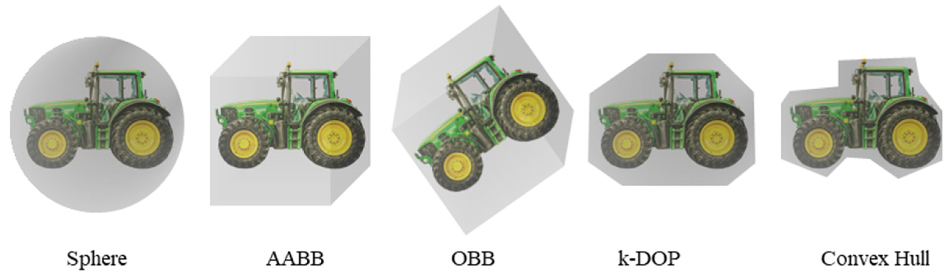
The most common form of broad-phase collision detection is to use a bounding volume to surround an object and to determine whether there is an overlap between the bounding volumes. The collision between machines in a drilling system is to determine if there is an overlap of encased 2D or 3D figures. Shapes are subdivided into spheres, boxes, convex hulls, and other forms according to the way the objects are wrapped. The most intuitive and simple calculation process is to use spheres. It is the simplest to implement (just counting the distance between two devices to determine a collision), but it contains too much unnecessary space. There is a risk that a collision determination may occur even if there is a sufficient distance in the case of a specific part.
In most cases, it is sufficient to apply the box-type bounding volume. There are two main types of bounding boxes, i.e., the axis-aligned bounding box (AABB) method, which considers only the straight movement of a cuboid, and the oriented bound box (OBB) method, which considers rotation as well. When an AABB is simply applied to n boxes, it checks whether O(2) intersects object pairs. If one aligns all of the x, y, and z axes and applies the method of checking whether the projection sections on each axis overlap, O() is required to align, and O() is required to check. For some objects, there may be a disadvantage in that the size of the box becomes too large when a simple AABB is applied. In particular, when the object’s local coordinate system rotates with respect to the global coordinate system, and the object has an elongated shape in the axial direction of the local coordinate system, such a disadvantage becomes greater. In this case, the minimum cuboid surrounding the object is the oriented bounding box.
A convex hull can cover the object very tightly, but it requires too many calculations. Among the bounding volumes, the most intuitive form is the bounding box, and the improved k-discrete orientation polytope (k-DOP) method is also used extensively. This is a method of cutting out unnecessary parts at each corner in a diagonal direction along with the
x,
y, and
z axes of the existing AABB. In 2D, 8-dop is used to store the maximum and minimum values in four directions, and 14-dop is used in 3D. Collision checking is almost identical to the AABB but in a more extended form. That is, the overlap of each section is checked not only on the existing
x,
y, and
z axes but also on the diagonal axis. Collision is checked by a separating axis theorem.
Figure 2 shows an example of applying the five types of bounding volumes described above to a tractor.
Multiple bounding boxes may be used for one machine. That is, instead of setting only one bounding volume surrounding an object, the bounding volume is set for each internal part of the object. The arrangement of the bounding volumes is stored in the form of a family tree. This kind of subdivision has two main advantages. First, it minimizes the invalid space that inevitably occurs when encasing the machine with only one box. In addition, the efficiency increases because it gradually uses a smaller bounding volume as it descends to the terminal node of the tree. Since the spacing is close between the boxes in the same family tree, overlap can occur frequently. To avoid this, a hierarchy must be configured through the family tree, and the bounding box in the same equipment must not be checked for collision. The ACS communicates with programmable logic controllers (PLCs) or the control room on the drilling network.
Table 1 shows the hierarchy of the machines under the supervision of the ACS. The movement of the lower systems of each piece of equipment is limited by the kinematic constraints of the upper unit. In this paper, it is assumed that six machines consisting of four different types are operated. There is one top drive, one catwalk, two tongs, and two racking devices. The overall equipment layout and collision detection algorithm are the same as those proposed by Nguyen et al. [
11]. The approximate role of each piece of equipment in relation to the pipe-handling process is as follows. The top drive moves up and down and receives pipes through an elevator that rotates about a pivot. A catwalk is a device that receives tubulars from the pipe storage area using a crane, and it moves them horizontally to the drill floor. A racker is a machine that has a column which rotates 360° on a trolley that moves along a rail from side to side, and three robotic arms are attached to the column. A tong is used to grip drill strings and apply torque when making up or breaking out drill pipes.
2.2. Core Module and Bypass Mode
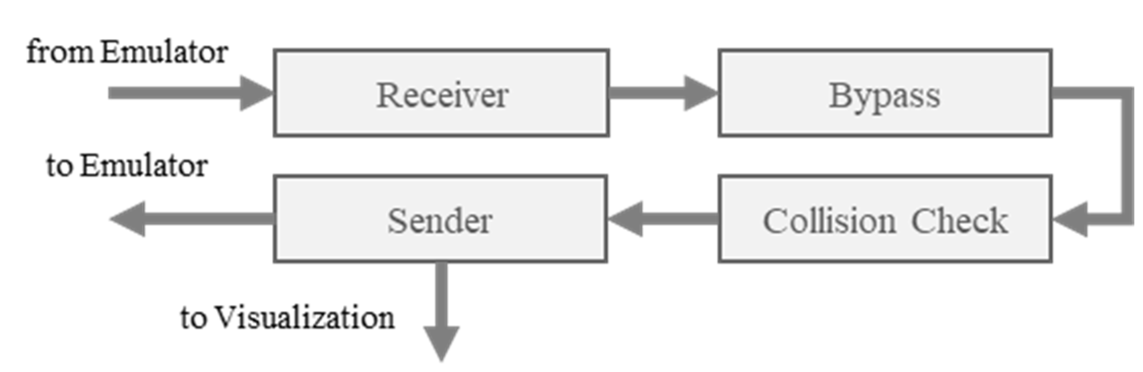
Figure 3 shows the data flow of the ACS core mentioned in
Figure 1. The ACS receives information about the location of the equipment from the network related to drilling control, but in the case of the digital twin, the emulator is configured separately to enable simulation. The ACS core module receives information related to the movement of equipment from this emulator. Bypass control input is checked first, and then it is reflected in the collision check.
Bypass control is used when it is necessary to stop and move the application of collision avoidance logic to equipment when the machine is stopped by a signal sent from the collision avoidance system. This includes cases in which equipment is moved to a specific area for maintenance or other reasons or when two pieces of equipment need to be separated in a collision situation. In relation to the collision avoidance system of drilling-related equipment, it generally can be divided into two cases, i.e., ignore and release. These bypass functions are implemented in the form of a switch box in the smart machine integration system. Since the switch is turned on in the standby state, the function is activated. Because it is a very important function, it is usually operated only by senior officers. The ‘Ignore’ signal is a function that allows certain equipment to continue operating in a ‘sensor signal unstable’ condition in the drilling yard. The objective is to prevent unnecessary stop signals from being generated due to incorrect location information. It has the effect of making the equipment invisible to other equipment in the work area. When the ignore switch of a certain device is turned on, the collision avoidance system ignores the location information received from the corresponding device and does not notify other devices of the risk of a collision. Therefore, even if several pieces of equipment, including the corresponding equipment, are located in the area where a potential collision may occur, a stop signal is not sent to the other equipment. A release signal is what makes the equipment unresponsive to a stop signal with any other equipment generated by the collision avoidance system.
The result of the collision check performed in the ACS core is sent to the emulator and visualization modules. The signal sent to the emulator module contains information that allows the bypass situation and the collision result to be reflected in the emulator. The visualization module sends signals to display the bypass situation, including the position and attitude of the equipment.
3. Design of the Display System
3.1. Machine Emulator
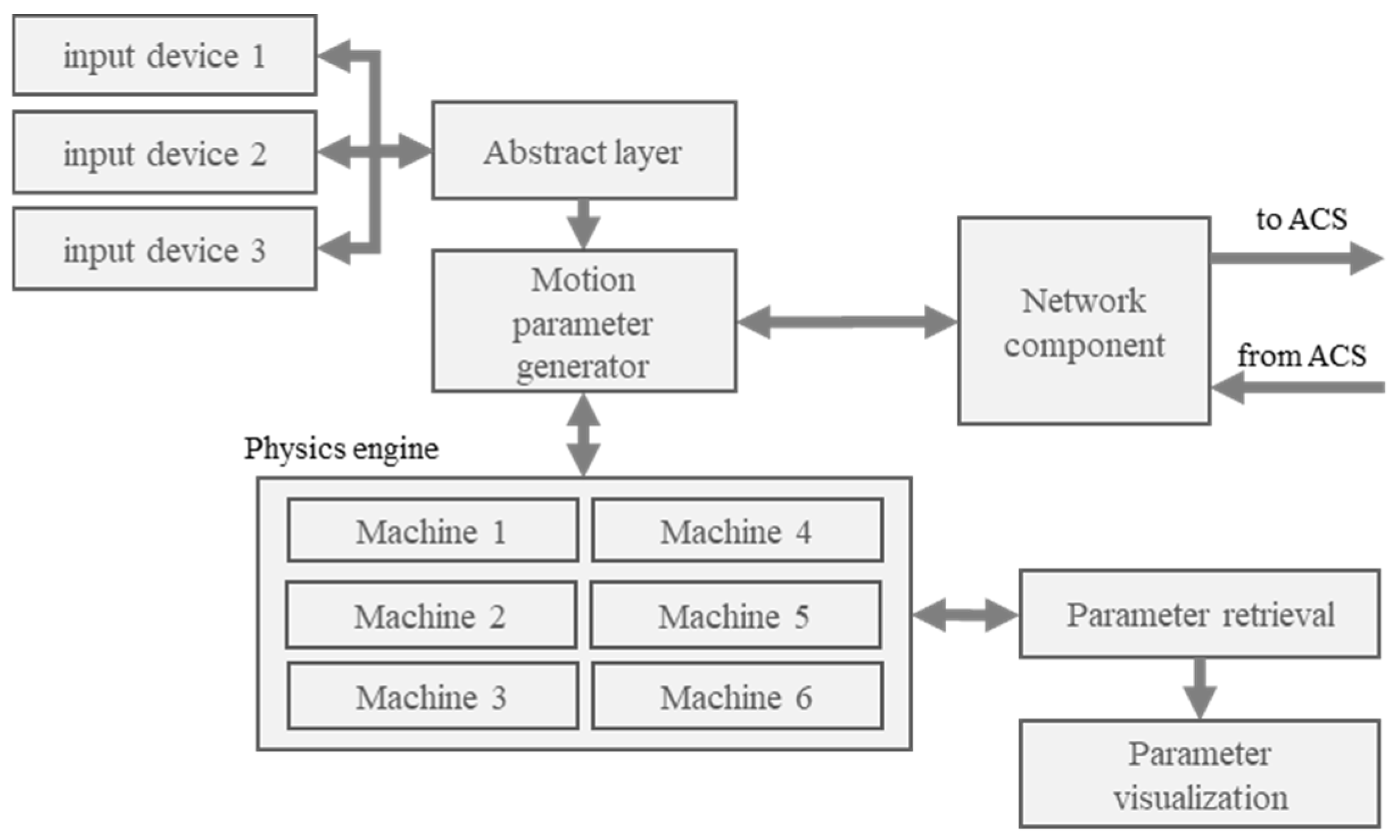
The machine emulator is a module that generates commands to operate equipment for the logic check of the ACS and processes motion control according to signals received from the ACS. The overall structure of the emulator module is shown in
Figure 4. Input devices refer to various methods such as joystick, keyboard, mouse, and touch screen. Those devices allow individual machines to be selected and operated for manipulating the drilling works. Signals generated by input devices are converted into basic commands related to movement through an abstract layer. The basic command sets the minimum value to −1 and the maximum value to 1, and the input signal is converted to a value between the two extreme values. This is to ensure that standardized commands are generated for signals from different input devices. A list of operating equipment and basic commands for the motion of the equipment are generated and sent to the motion parameter generator in this process. The motion parameter generator produces actual motion commands by matching the basic commands generated in the abstract layer to the physical specifications of the equipment in the configuration file. The motion commands such as the velocity, acceleration, angular velocity, and angular acceleration are determined at the level of the subsystem that is being manipulated by the input devices. Subsystems may be connected to each other through the hierarchy. For example, a racker has a column installed on the trolley, and three robotic arms are operated individually. Therefore, the final position and posture are calculated by using the velocity and acceleration information from the physics engine to which the dynamic and kinematic constraint is applied so that they can move together by checking the dependency related to the movement. The motion parameter generator sends these positions and attitudes to the ACS core to perform the collision check. Meanwhile, motion parameters and system parameters related to the current operation of the equipment can be checked through parameter visualization. The parameters used in the emulator are summarized in
Table 2.
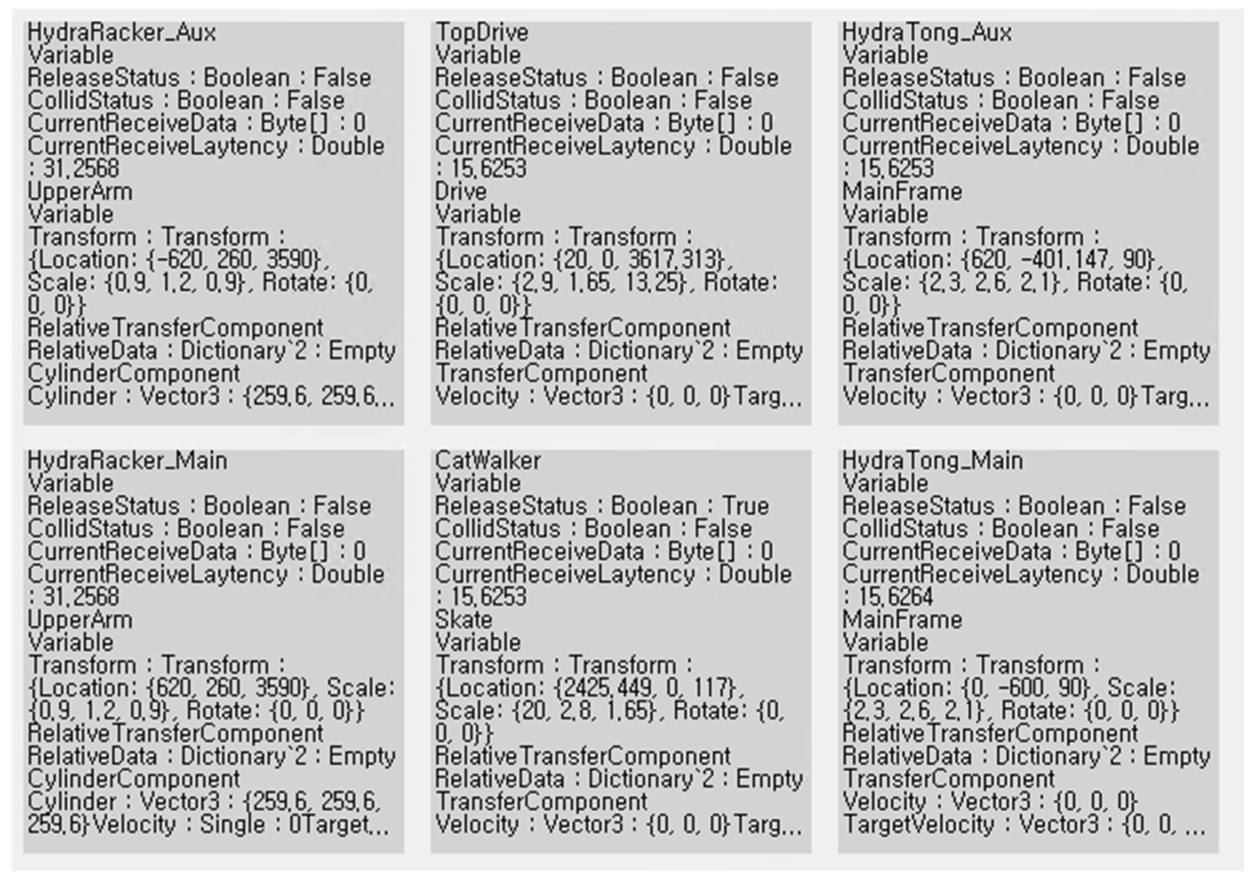
In the retrieval unit, parameters are organized into machine name, refreshRate (visualization period), simEvent (event related to simulation such as bypass), and machineEvent (information related to equipment). System parameters include latency indicating communication speed, collision status indicating collision situation, and release state indicating the bypass mode of the device. This organized information is sent to the parameter visualization component and displayed so that the status can be checked by the operator.
Figure 5 is an example showing the values of the parameters that the operator can check in the emulator.
3.2. Vessel Motion
When analyzing incidents in the visualized ACS, information related to the movement of the floating body is also required. In relation to the real-time motion data of a ship, it is necessary to display attitude information from the sensor. Motion data may include the speed and acceleration of the floating body. In addition, a module that generates the motion required for simulation is installed to make the motion of the twin model of the floater. For this purpose, STR’s Deskpilot, a commercial simulator, is connected to the system [
12]. Deskpilot is a simulator based on the motion analysis program of Korea research institutes of ships and ocean engineering (KRISO). Various environmental factors, such as waves, winds, and currents, can be changed freely for various types of ships. As used in the actual ship’s automatic identification system (AIS), various sets of sensor information are created according to the NMEA-0183 protocol, which is a protocol defined by the national marine electronics association (NMEA) in the United States since the 1980s, and it is an interface and data communication protocol between marine equipment. Although NMEA 2000 has been distributed, many devices are still communicating based on NMEA-0183, and since it can be applied to NMEA 2000 through a separate converter, the 0183 protocol is applied [
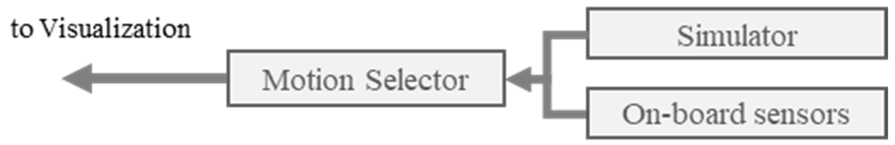
13]. The motion selector allows selection between the data from the ship motion simulator and the data from the navigation-related sensors installed on the actual ship. Then, the data are sent to the visualization module and used as information to describe the work condition more precisely.
Figure 6 shows the basic function of the motion generator module.
3.3. Database for Retrieval and Display
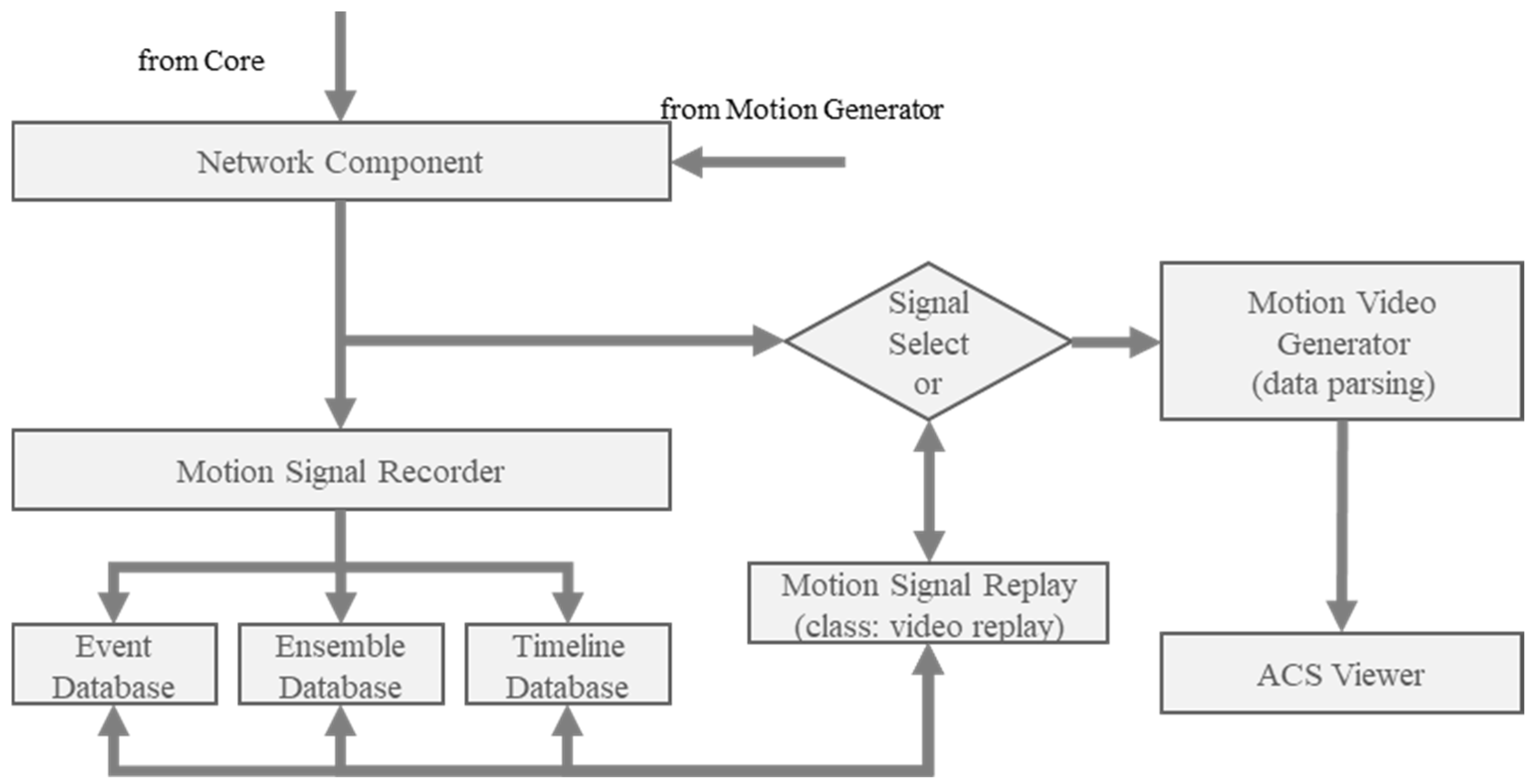
All information, including the ship motion information and equipment status, is sent to the visualization module.
Figure 7 shows the components and data flow of the module. Signals received from the core and motion generator modules are simultaneously sent to the database and the signal selector, and mongoDB is selected as the default database. As one of the non-relational database management systems, mongoDB has the advantage of faster processing speed compared to a relational database management system (RDBMS), such as My structured query language (MySQL) [
14]. This method is used considering the characteristics of the ACS that needs to process a lot of video information. The database consists of three collections, i.e., ensemble, event, and timeline. The ensemble collection stores all information transmitted from all of the machines to the ACS. The event collection is used to save the time and contents when an ACS detects an unusual event. The timeline collection is a space that stores all data for every minute. It is used to quickly access a specific point in time.
In the case of the replay mode, there are two main ways to access the database, i.e., returning to a specific point in time or returning to the time of the event. When returning to a specific point in time, information is reproduced by accessing a location that matches the first visual information of the timeline collection. When returning to the time of the event, the display module tries to access the timeline collection after checking the time in the event collection. The module plays one minute of data before the event and one minute of data after the event for a total of 2 min. In the visualization module, a window is set for selecting real-time data and playback data. The signal selector distinguishes the real-time mode and the playback mode. In the real-time mode, the data entered into the visualization module through the network are sent directly to the visualization software. In the playback mode, the information stored in the database is sent to the visualization software.
When a special situation occurs, the occurrence time and equipment name are displayed on the screen, and when multiple events occur, they are displayed sequentially. Since it is managed in a separate list, deletion on this screen does not mean deletion from the database (DB), so it can be accessed again at any time. If the operator selects a specific event and selects ‘replay’, it will change to the ‘replaying’ mode as shown in the following screen, and the contents stored in the DB will be displayed. If the operator presses the ‘real’ button at the bottom right of the screen, it changes to real time. During playback, the operator can select the replay speed, and stopping should also be possible.
The most important thing in replay or real-time operation is that the operator can check the status of each device using a digital twin. In this research, it is implemented with Unreal Engine, where the work status can be accessed from any angle by manipulating the viewpoint. The main purpose of this approach is to facilitate the analysis of the accident situation. In addition, an interactive window that can display additional data of each device was installed to enable analysis.
A more secure system can be created through virtual operation in many cases. In this system, human factors have not been considered yet. This system is planned to be used for the purpose of deriving the requirements of a system attached to humans in conjunction with the drilling simulator and verifying the work process that can be performed safely in relation to the drilling process. The process of converting the ACS that exists as a part of the overall system into an independent system is implemented. Configuring the entire system completely at once is a very expensive and time-consuming task. It is expected that it can be used as an example of how to implement a digital twin of a lower level in each system and perform a given mission through solidarity between systems.
4. Simulation
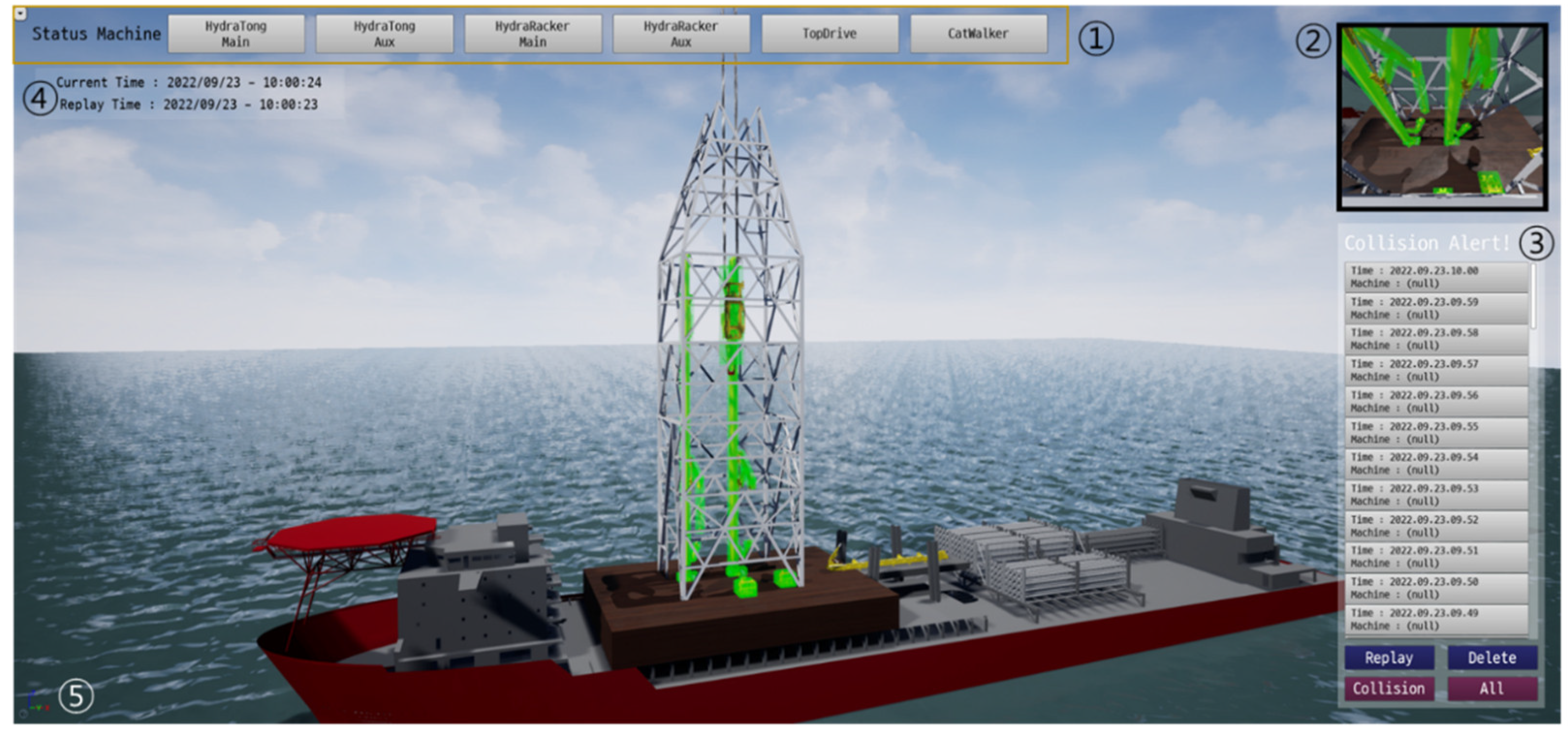
The representative screen based on the developed system is shown in the
Figure 8. The meanings of the numbers in the figure are explained as follows.
① Machine status bar: It is possible to directly check the status of the equipment used for drilling operation. If one selects a machine name, a window box showing the status of the device appears. If the operator selects ‘Vessel motion’, information related to the motion of the vessel is displayed.
② Time bar: Displays the time. Two perspectives are used in the developed system. The current system time is for work being performed in real time, and when the recorded screen is played back, the replay time is displayed separately.
③ CCTV box: It shows the line of sight of the CCTV cameras installed on the structure. It is possible to observe the working status with the position and angle installed on the actual drilling vessel.
④ Play mode bar: It displays whether the current play mode is the real-time mode or the replay mode, and it includes the play time and progress bar in the case of the replay mode. In the case of the real-time mode, a mark of ‘recording’ appears, indicating that the current status of the work on the screen is being stored in the database.
⑤ Replay selection: Includes a function to switch from the playback mode to the real-time screen, a function to select a playback speed, and a function to select a playback time.
Figure 8.
Outlook of display system developed. ① Machine status bar; ② Time bar; ③ CCTV box; ④ Play mode bar; ⑤ Replay selection.
Figure 8.
Outlook of display system developed. ① Machine status bar; ② Time bar; ③ CCTV box; ④ Play mode bar; ⑤ Replay selection.
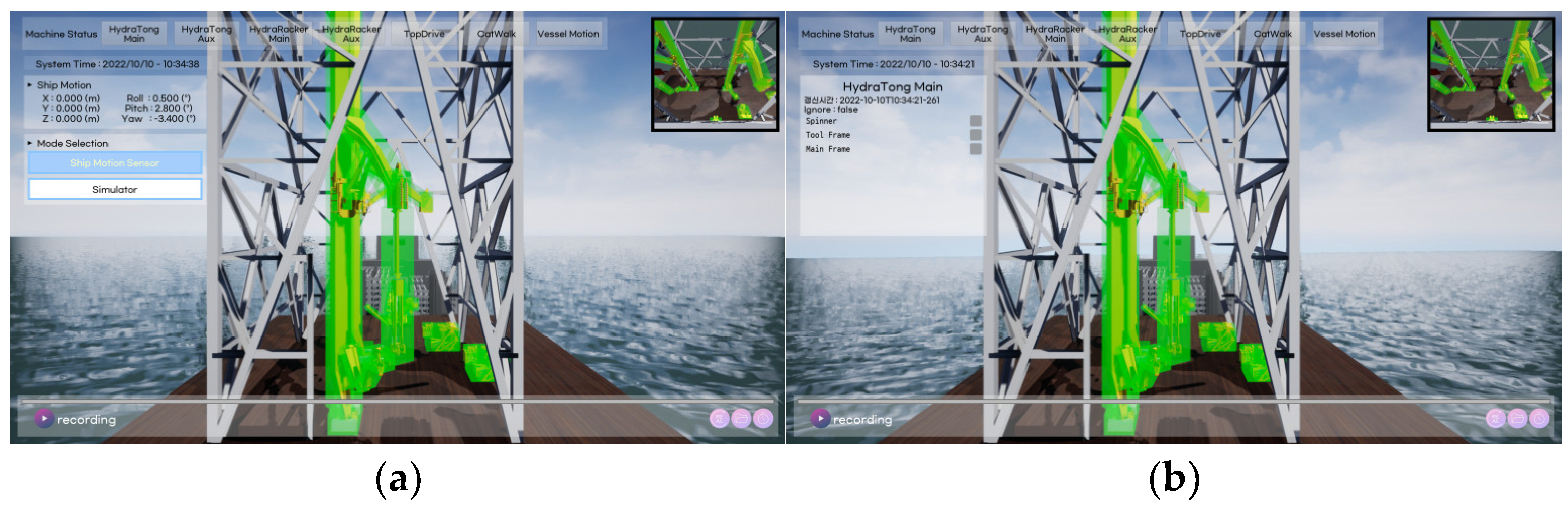
Figure 9 shows an example of using the machine status bar described in item 1 of
Figure 8. When vessel motion is selected, information from the ship motion generator is expressed. In mode selection, information from sensors and information from motion simulation can be selected. Currently, only the position and attitude information of the floating body is included, but when connected to the control system of the ship, all necessary information may be included. When the equipment is selected, the subsystems of the equipment are expressed so that it is possible to indicate where the problem occurred.
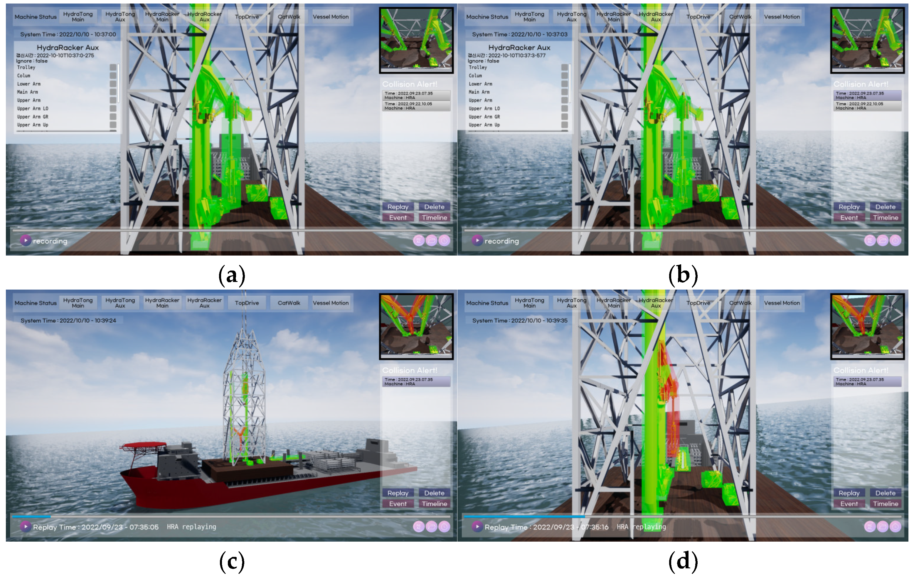
The record of when a collision occurs is displayed on the window, and the process of selecting and reproducing the event is shown in
Figure 10. If a collision-related event occurs, workers use the bypass mode in the field to resolve the situation. Separately, the event history is stored in the database. All data are designed to be displayed in the collision alert bar (a). A user using the ACS display system can select and play an event to check from among the events displayed on the collision alert bar (b). At this time, since it is still in the real-time mode, ‘recording’ is shown on the play mode bar. After selecting a playback point, the replay button is pressed to start the replay mode (c). The content of the play mode bar indicates the playback time, which is different from the current system time. By moving the viewpoint during playback, detailed observation of the event is possible (d).
The position of the camera showing the screen displayed on the CCTV window is fixed to the structure. The inspector can only zoom in or out or tilt the screen slightly. Therefore, only a limited field of view is available. Using the developed system, it is possible to show the situation in which the accident scene can be checked by rotating the screen in the desired direction in the playback mode. At this time, when the relevant equipment is selected from the machine status bar, the data of the equipment are displayed on the screen. The record displayed in the collision alert window can be deleted by using the delete button after checking the item. However, related information still remains in the event collection of the DB, and screen playback through it is always possible. Returning to the real-time mode after playback is performed by pressing the button as described above.
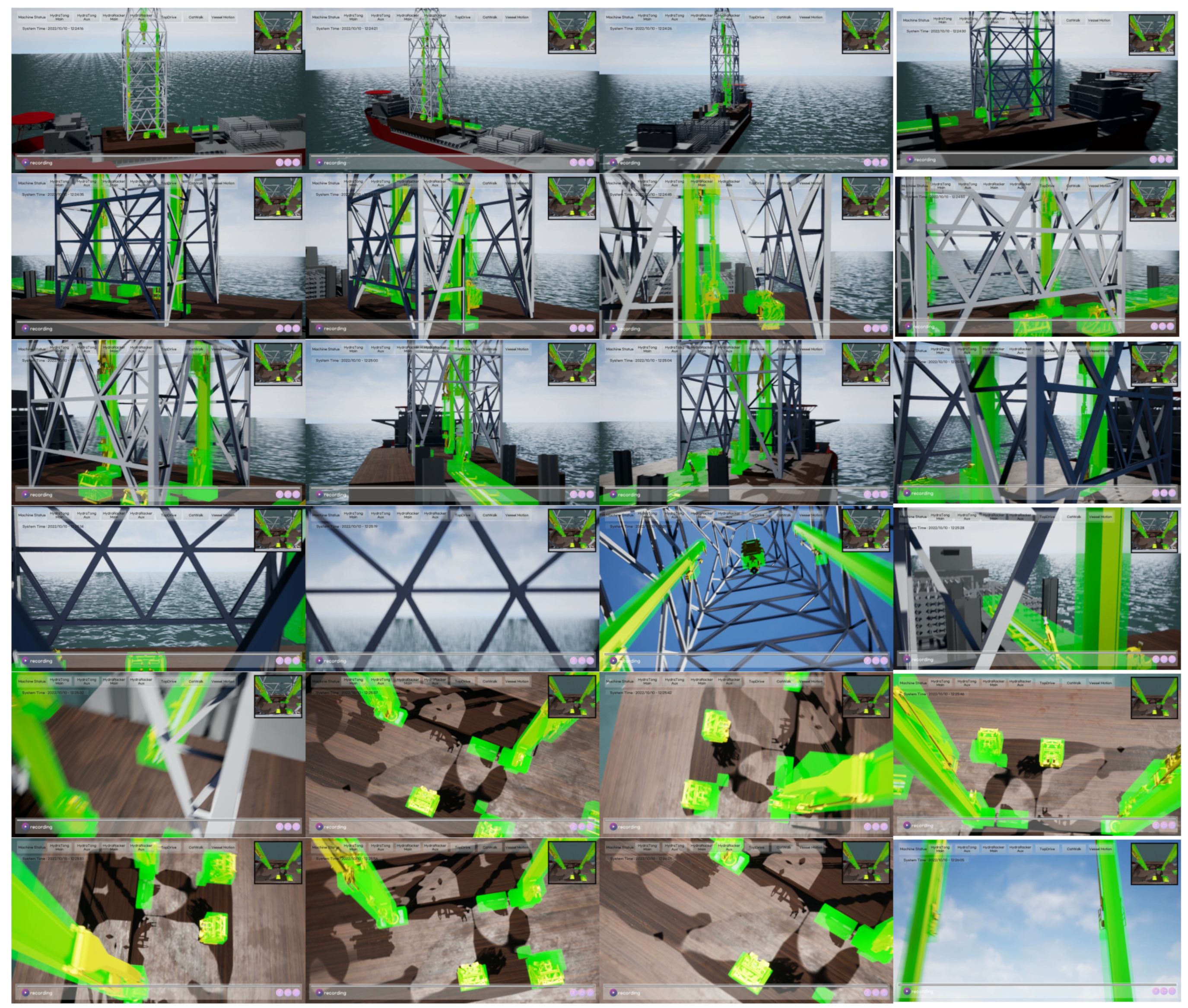
Figure 11 shows an example in which the user checks the status of equipment while continuously moving the viewpoint through manipulation in the real-time mode. While working in the real-time mode, the movement of ACS-related equipment can be checked from various angles. Since the same operation is possible in the replay mode, it is possible to make a more precise analysis when an event occurs.
5. Conclusions
A methodology for visualizing the anti-collision system of offshore drilling rigs was presented by applying the digital twin design process. By storing the data related to the operation of the ACS, it is possible to analyze dangerous situations in real time or through the replay function. In addition, the development direction of the collision avoidance system and the application field of visualization were considered. According to the system-based digital twin design method, it was configured to enable mirroring and monitoring of offshore drilling equipment. In addition, an input/output system for virtual operation was implemented through the simulation module. By storing and managing the data generated by the ACS, collision avoidance and safety analysis became possible. The data transmission/reception system was designed to be able to interoperate with other digital twin systems and ultimately became the basis of a digital twin alliance for the entire vessel.
The display is organized to show as much information as possible for collision analysis. Basic functions such as the movement of the floating body, three display modes (real time, event playback, and specific time playback), and the screen replay speed controller were implemented to facilitate event-related analysis. In the case of the movement of the floating body, the current state of the real-time operation can be displayed, or the movement occurring in the simulation vessel can be selected and linked. In the case of the playback mode, the operator can replay by selecting the data stored in minutes or by specifying a particular point in time when an anomaly related to a collision occurred. The operator can return to the real-time mode at any time. In the replay mode, the information stored in the database at that point in time is displayed. Overall, one can analyze the general situation through the movement of the viewpoint in real-time and playback modes. All of the functions of the display system were checked successfully, and the information of the equipment is well-identified.
The developed system may include human safety parts in the future. Currently, it is aimed at a system that prevents machine–machine collision, but if proper sensors are attached to a human worker’s body, it can be expanded to a system that can review and record the possibility of a human–machine collision. If the sensor is modelled and applied to the developed system, the developer will be able to check the sensor’s performance. It may also be used to detect and improve the hazardous behavior of the worker. It can be expected to be applicable to the design of an autonomous ship’s automatic berthing system by expanding the research field. In general, the prevention of collisions of ships is approached from the perspective of path planning. It is to adjust each ship’s path so that the paths of two ships do not overlap, which can be executed by applying rules such as COLREG [
15]. However, a platform for predicting collisions between ships located in close proximity and simulating control rules to prevent the collision is difficult to implement with conventional path planning methods. There are two things to consider in advance. First, in order to prevent collisions of ships at a short distance, the bounding figure should be created a little more precisely. In the case of ships of similar size, the exterior of the ship can be sufficiently covered with a 2D figure. However, in a situation where there is a height difference between ships, a 3D figure should be applied. This is because the complex shape of the fore and aft must be considered. Therefore, it is necessary to apply the k-DOP or convex hull method, and a way must be found to overcome the disadvantage of large amounts of computation being required. The second is the control of collision avoidance. Since general ships are underactuated, there are restrictions on the generation of control inputs according to collision detection. Therefore, the prediction and control of collision avoidance will be possible only when the response of the vessel to the control input and the effect of the marine environment are considered together.


