
SMURF: A Fully Autonomous Water Surface Cleaning Robot with A Novel Coverage Path Planning Method

Abstract
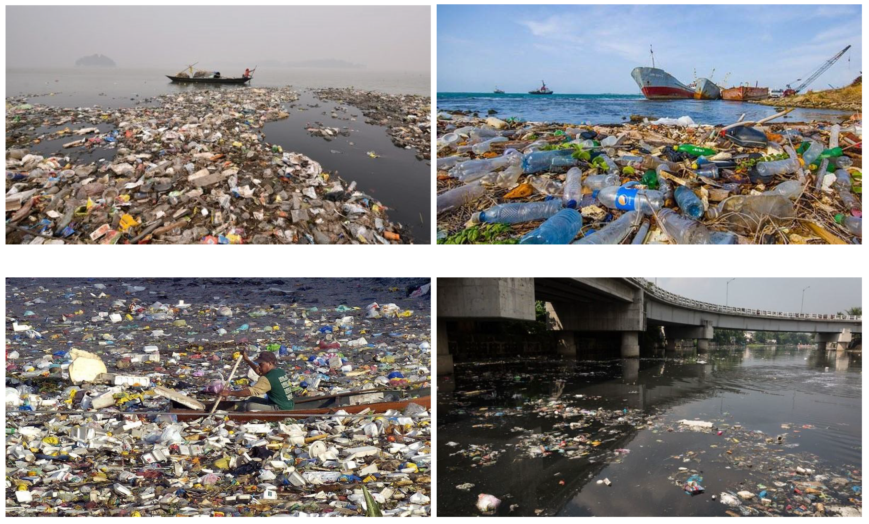
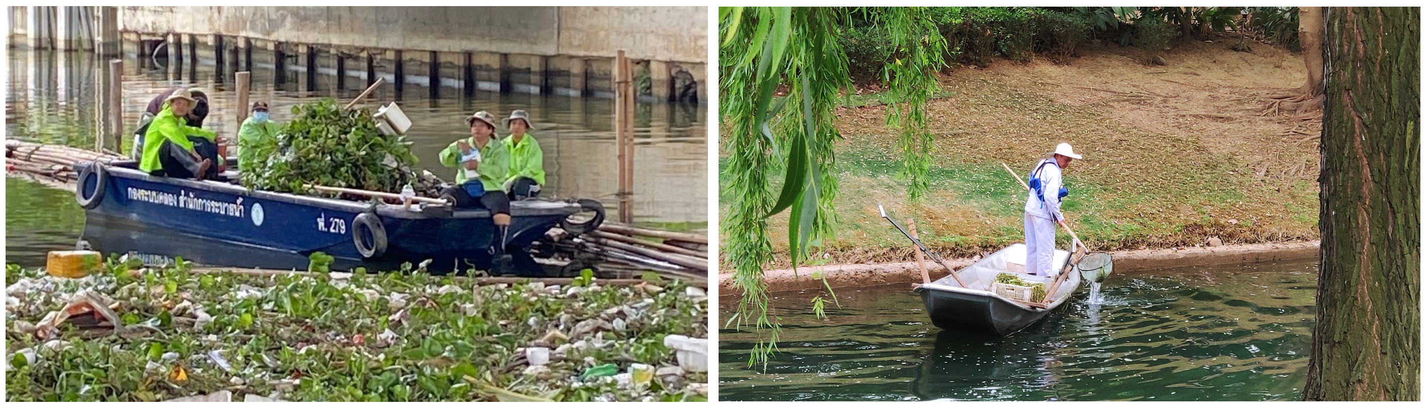
:1. Introduction
- We design a new robot that achieves fully autonomous water surface cleaning and significantly increases cleaning efficiency.
- We propose a novel CPP method for water surface cleaning and design an improved NMPC for water surface cleaning robots.
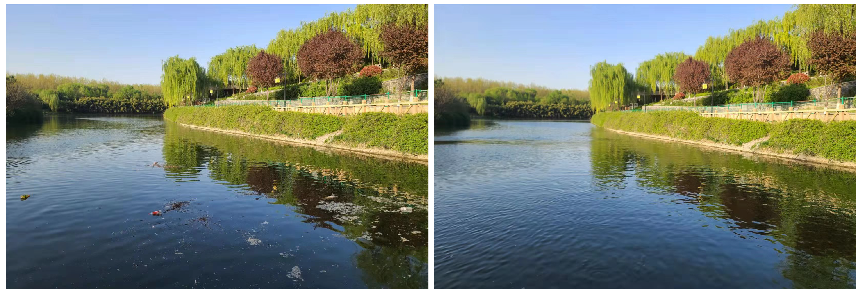
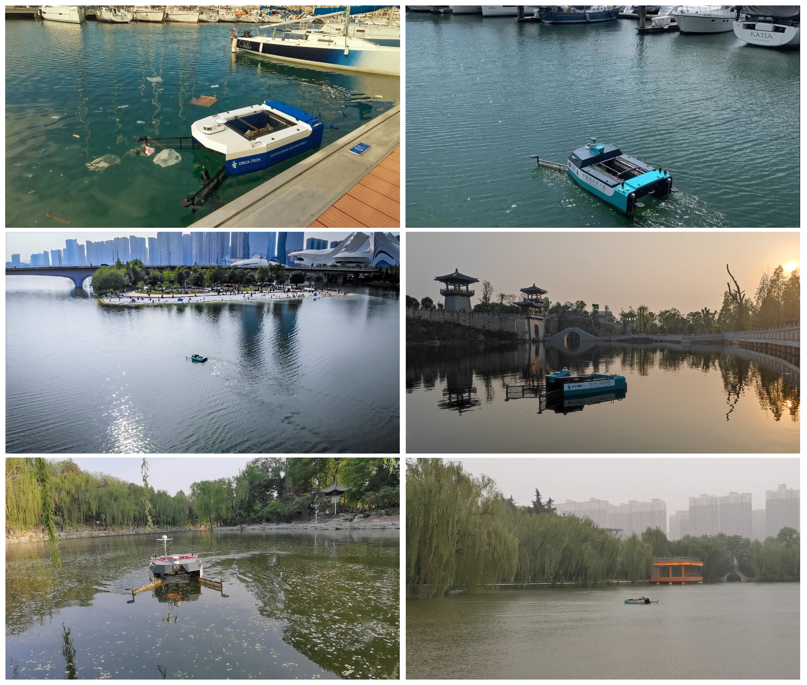
- We conduct real-world experiments in various water bodies to test the cleaning performance of SMURF.
2. Related Work
2.1. Water Surface Robot
2.2. Coverage Path Planning
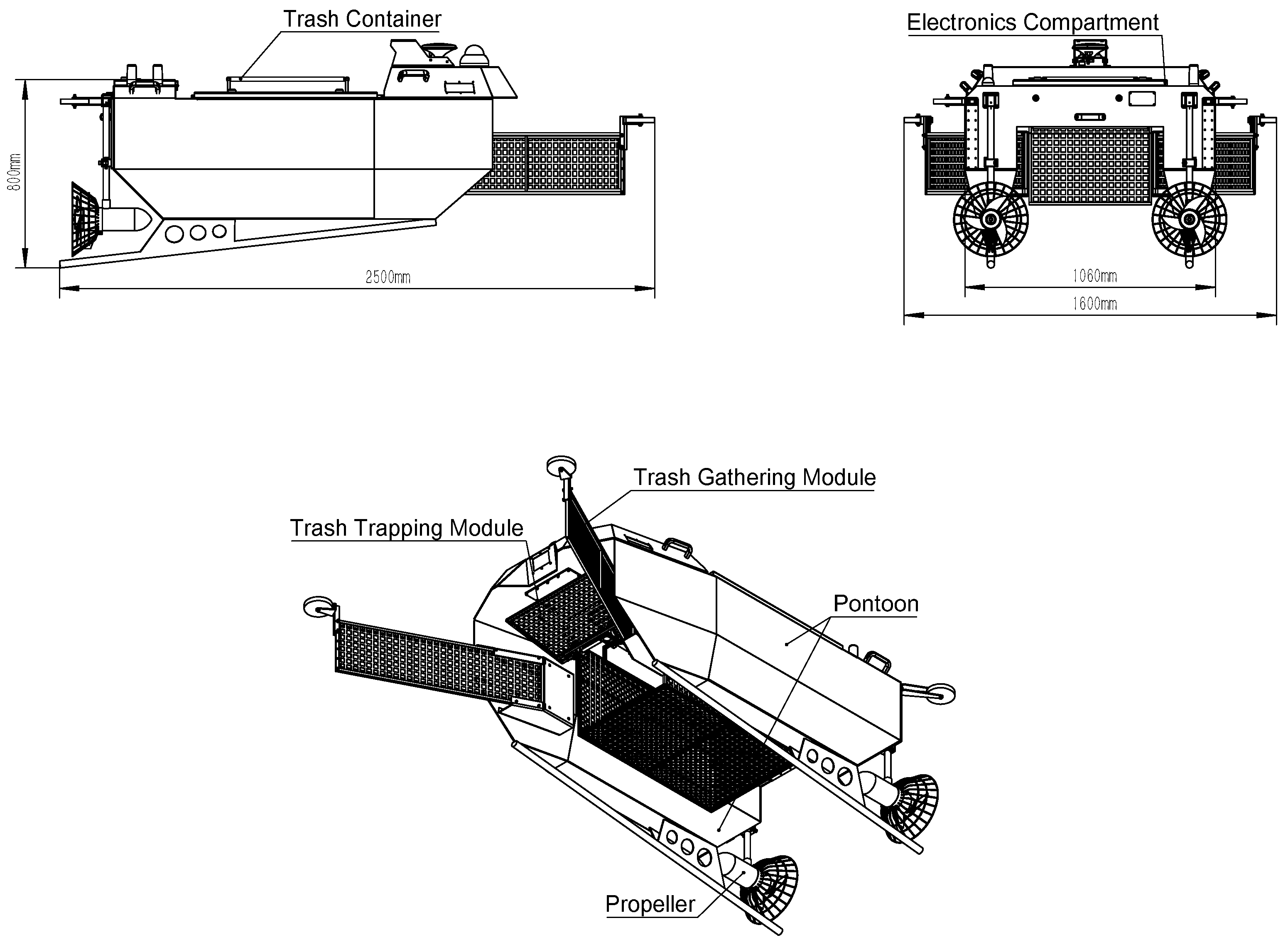
3. Water Surface Cleaning Robot Design
3.1. Hull Design
3.2. Hardware
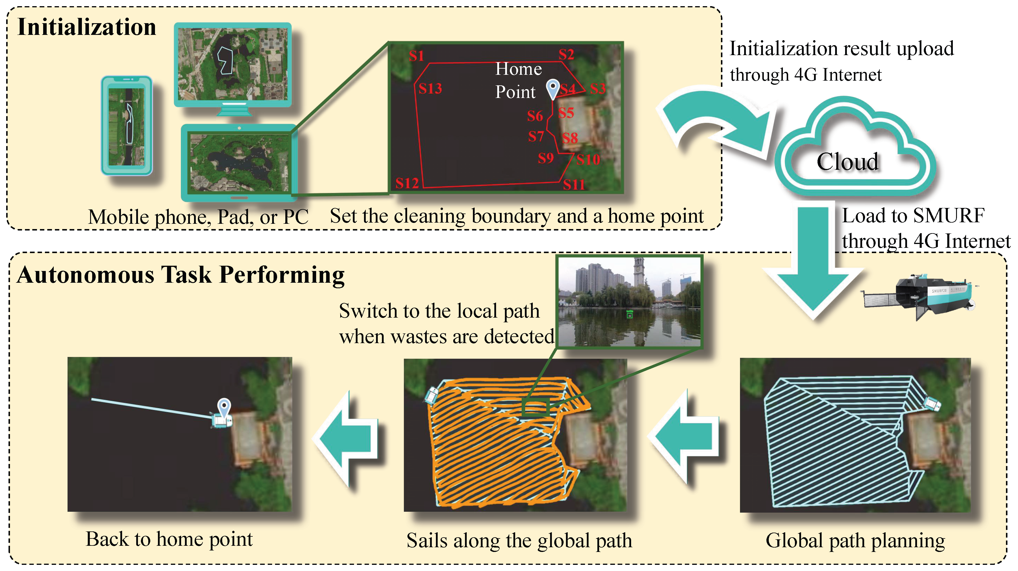
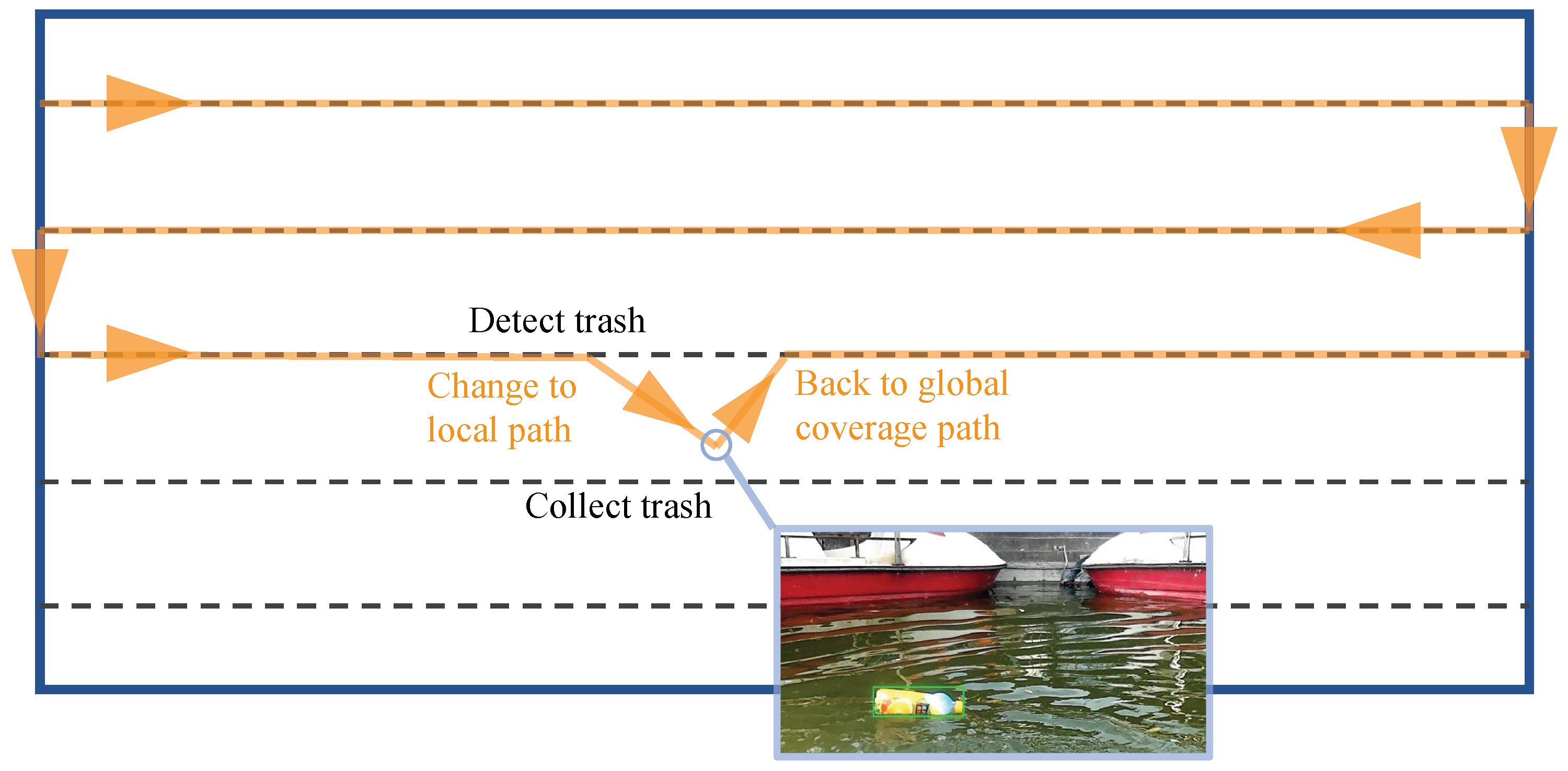
3.3. Working Procedure
4. Autonomous System
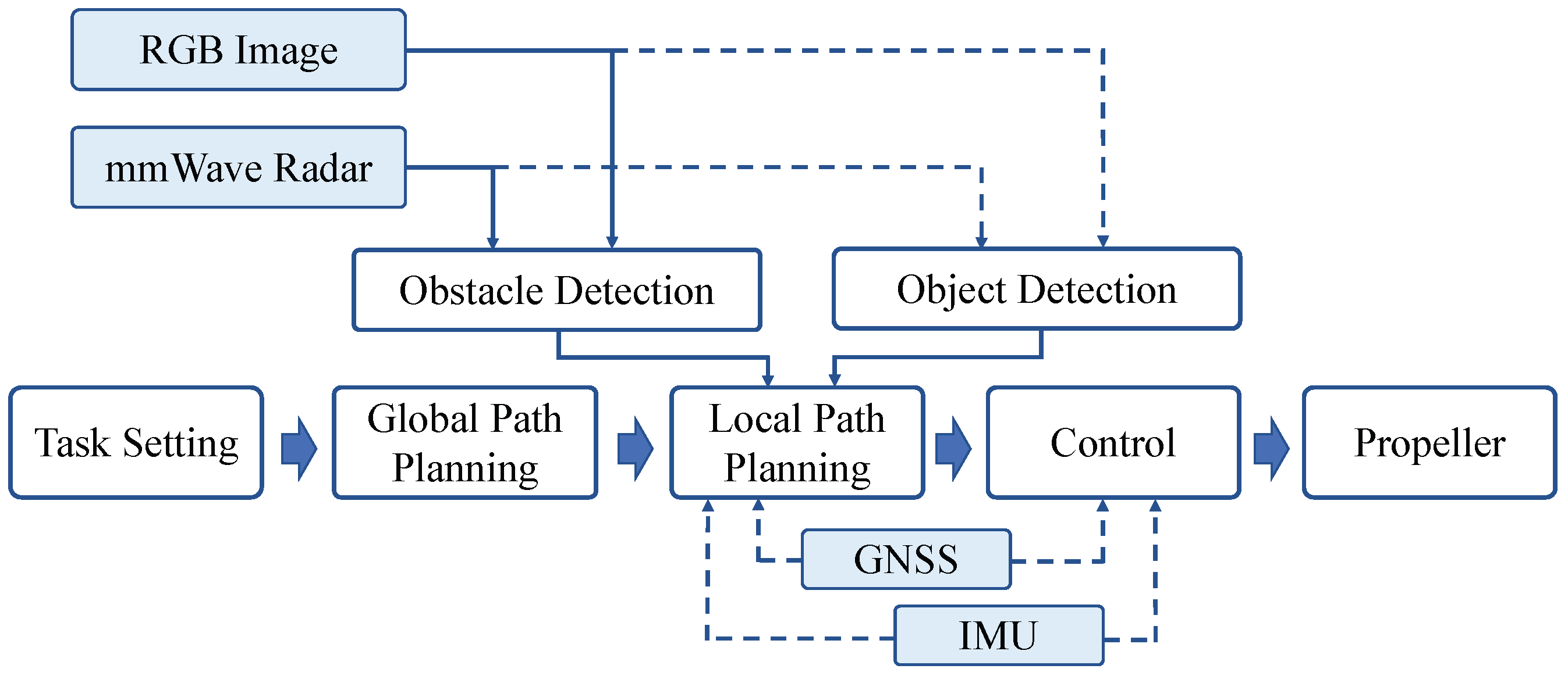
4.1. Autonomous System Framework
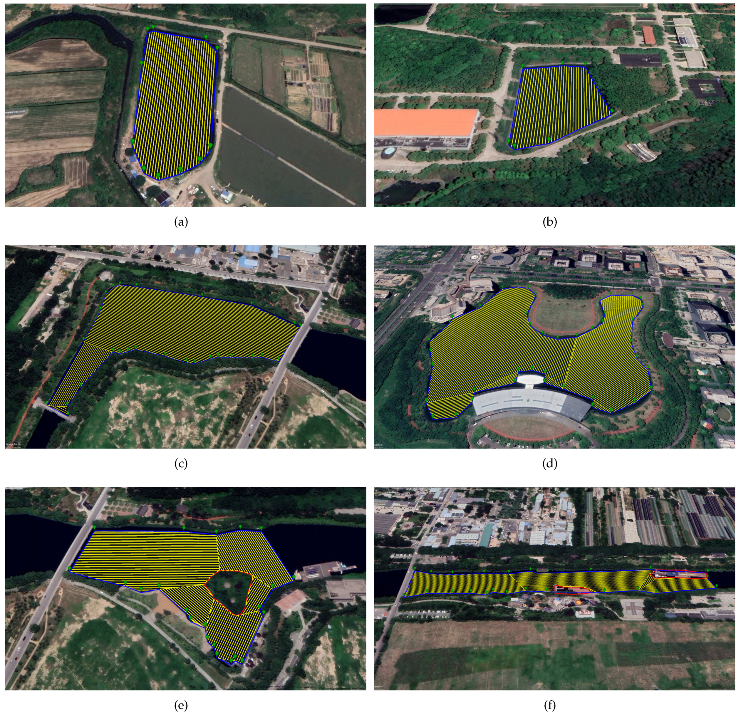
4.2. Water Surface Coverage Path Planning
| Algorithm 1 The WSCPP algorithm (for regular region). | |
| Input: Regular region with coordinates of boundary points in the region , width of single effective cleaning d | |
| Output: Optimal trajectory | |
| 1: | Define set of trajectories |
| 2: | for do |
| 3: | Compute the scan direction parallel to edge line |
| 4: | Generate multiple lines by translating line by space d until there are no more parallel line intersecting with the region edges. The generated set of lines |
| 5: | Define back-and-forth trajectory line set |
| 6: | for do |
| 7: | Calculate the intersection point set between and region edges |
| 8: | if then |
| 9: | Inverse points sequence |
| 10: | end if |
| 11: | Add into |
| 12: | end for |
| 13: | Add into W |
| 14: | end for |
| 15: | |
| Algorithm 2 The WSCPP algorithm (for irregular region). | |
| Input: Irregular region with coordinates of boundary points in the region } width of single effective cleaning d, obstacle set | |
| Output: Optimal trajectory | |
| 1: | |
| 2: | Combine the points in with points in as point set P |
| 3: | Apply triangulation to P and get triangle set [35]. Delete the triangles that are contained in the obstacles, and get the final triangle set T |
| 4: | Combine triangles in set T into multiple convex polygons, and get the sub-region set |
| 5: | Choose the sub-region that contains original boundary points and closest to the start point of the robot as the first sub-region , and . |
| 6: | while do |
| 7: | Delete from B |
| 8: | Generate coverage planning path using Algorithm 1. |
| 9: | if then |
| 10: | Define line x as the line connecting the end point of to the first point of . |
| 11: | Get all the obstacles that have intersection points with x, and sort the obstacles from the shortest to the longest according to their distances to the end point of , and obstacles set is . |
| 12: | Define the path bypassing the obstacles as u |
| 13: | for do |
| 14: | Calculate the intersection points of x and |
| 15: | Divide the boundary of into two parts by points |
| 16: | if both and are inside of the region then |
| 17: | Add the shorter one of and into u |
| 18: | else |
| 19: | Add one of and that is inside of the region into u |
| 20: | end if |
| 21: | Add u into |
| 22: | end for |
| 23: | end if |
| 24: | Add trajectory point set into |
| 25: | if there are sub-regions adjacent in B then |
| 26: | Set as the sub-region adjacent and closest to the end point of . |
| 27: | else |
| 28: | Set as the sub-region closest to the end point of . |
| 29: | end if |
| 30: | end while |
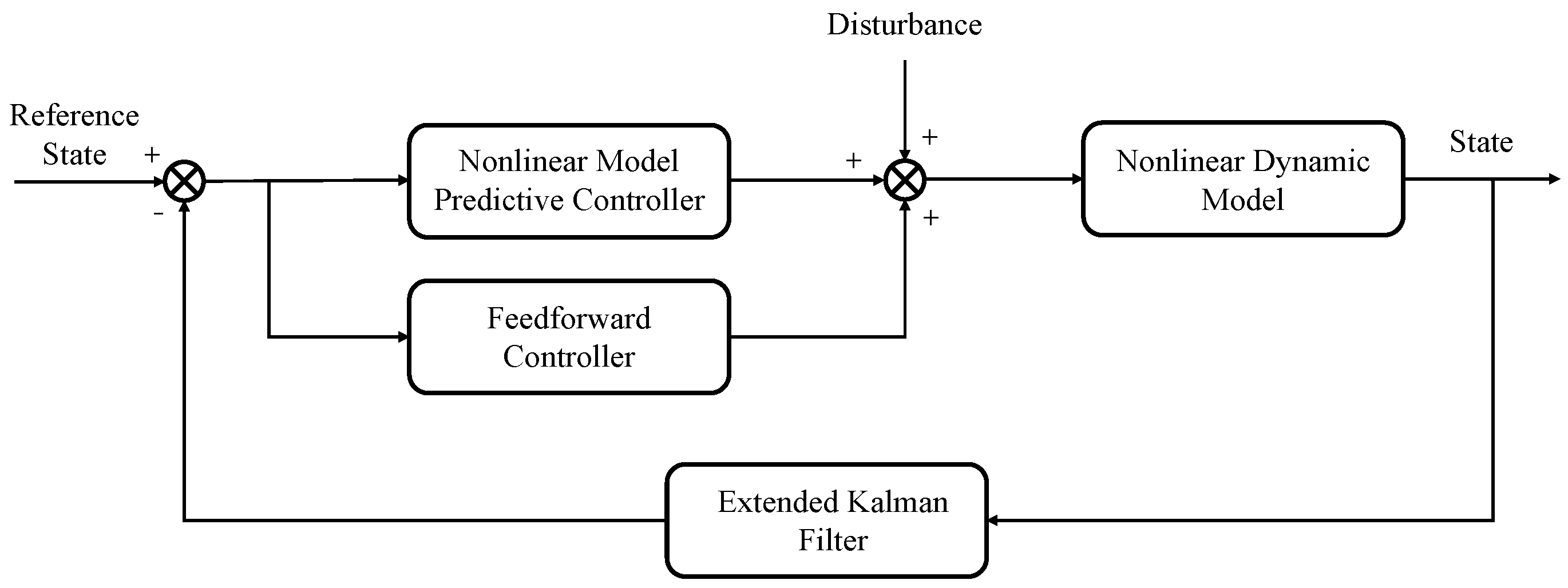
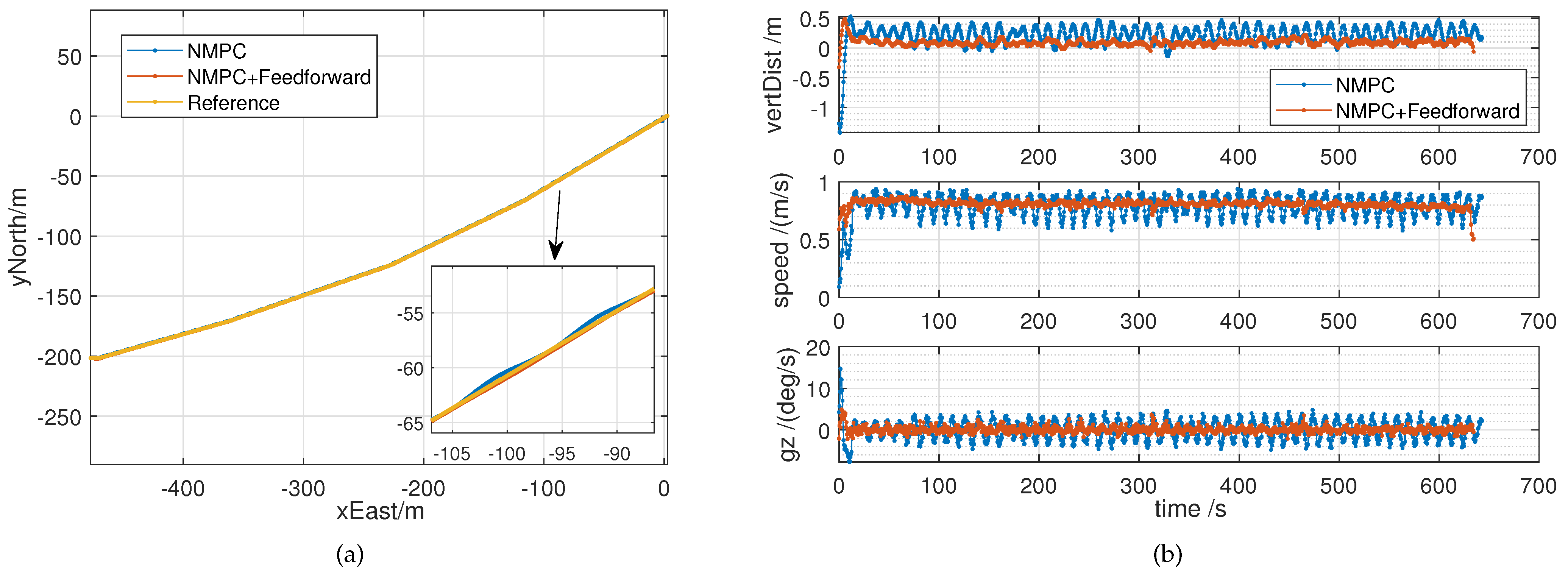
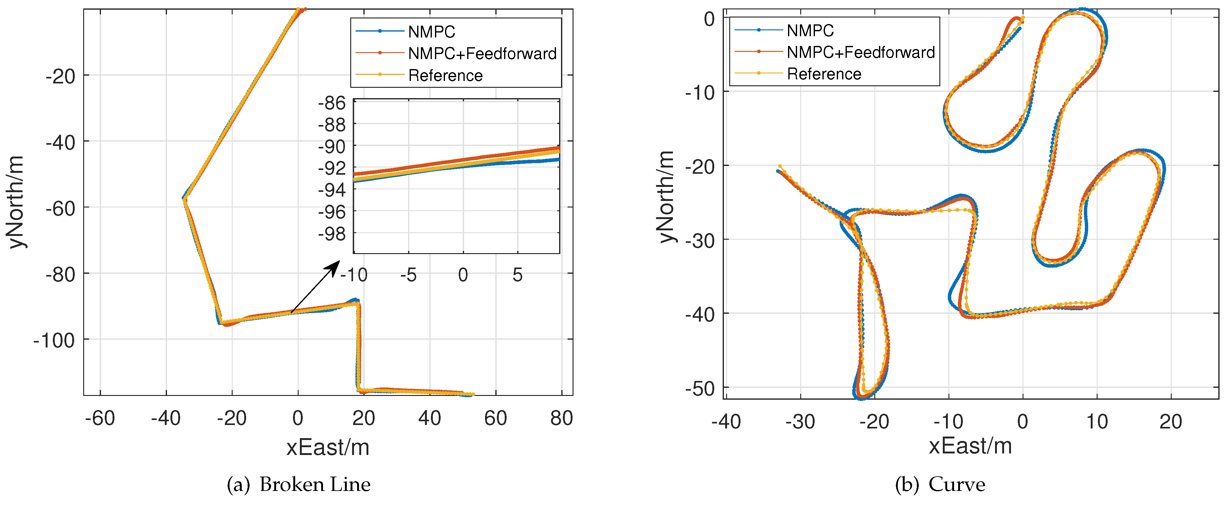
4.3. Improved NMPC
- In the process of operation, the mass of SMURF increases when collecting garbage, namely, , , , are time-varying matrix.
- In the garbage collection process, the distribution of garbage in the trash container is unknown. The nonlinear resistance matrix will change, which will cause an obvious deviation.
- Over time, the motor will age and wear out, which will result in a lower control input force .
5. Experiment and Evaluation
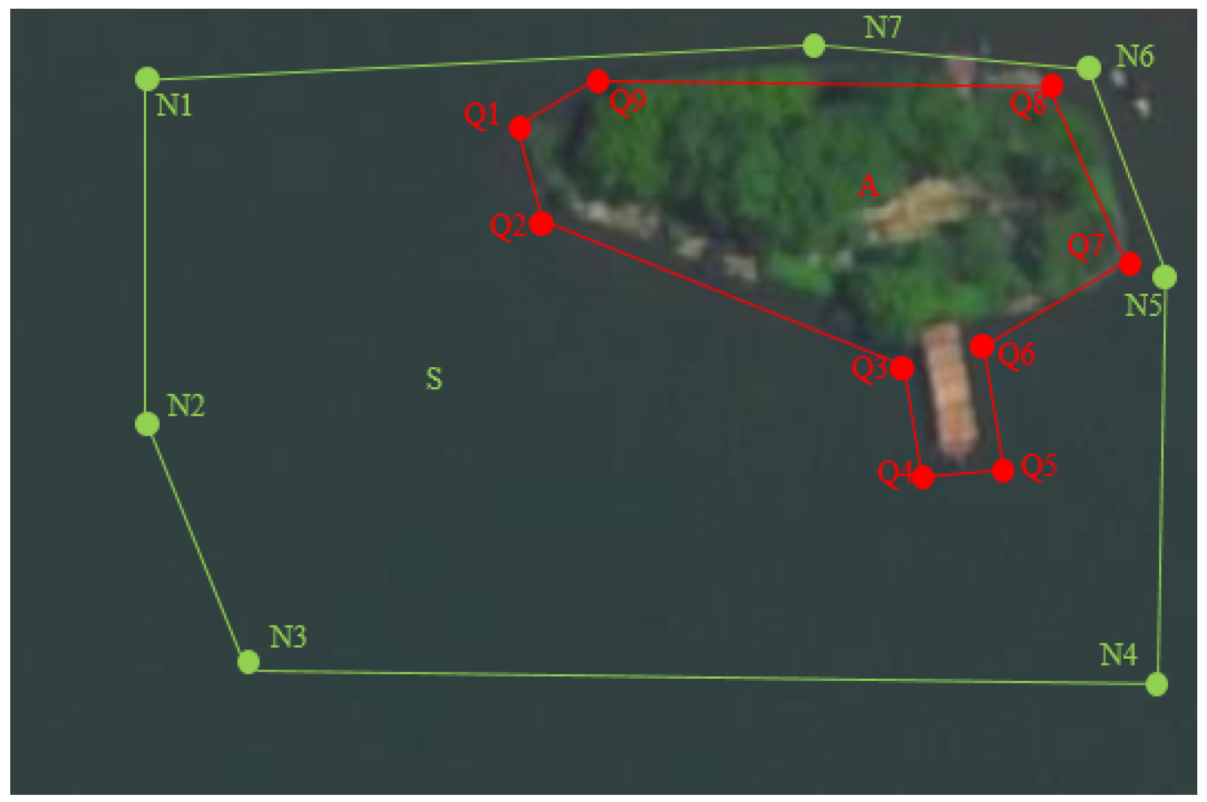
5.1. Water Surface Coverage Path Planning
5.2. Trajectory Tracking Evaluation
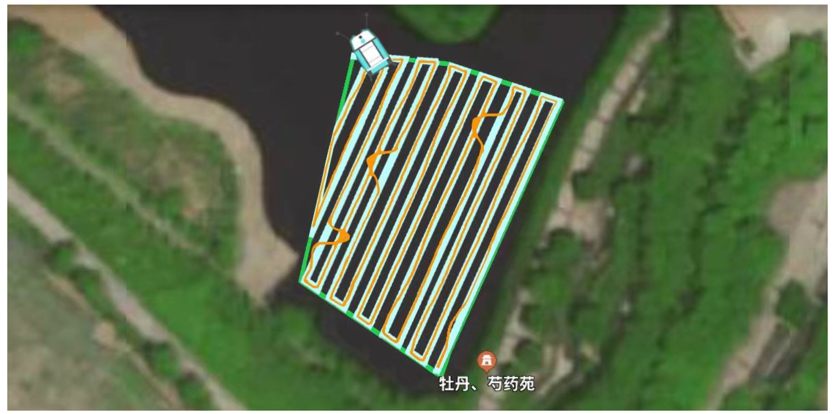
5.3. Water Surface Cleaning Performance Evaluation
6. Conclusions
Author Contributions
Funding
Institutional Review Board Statement
Informed Consent Statement
Data Availability Statement
Conflicts of Interest
Abbreviations
| CPP | Coverage Path Planning |
| GNSS | Global Navigation Satellite System |
| IMU | Inertial Measurement Unit |
| mmWave | Millimeter Wave Radar |
| NMPC | Nonlinear Model Predictive Controller |
| USV | Unmanned Surface Vehicle |
| UAV | Unmanned Aerial Vehicles |
| WSCPP | Water Surface Coverage Path Planning |
| RTK | Real-Time Kinematic |
References
- LI, W.C.; Tse, H.; Fok, L. Plastic waste in the marine environment: A review of sources, occurrence and effects. Sci. Total Environ. 2016, 566, 333–349. [Google Scholar] [CrossRef] [PubMed]
- Topouzelis, K.; Papakonstantinou, A.; Garaba, S.P. Detection of floating plastics from satellite and unmanned aerial systems (Plastic Litter Project 2018). Int. J. Appl. Earth Observ. Geoinf. 2019, 79, 175–183. [Google Scholar] [CrossRef]
- Compa, M.; March, D.; Deudero, S. Spatio-temporal monitoring of coastal floating marine debris in the Balearic Islands from sea-cleaning boats. Mar. Poll. Bull. 2019, 141, 205–214. [Google Scholar] [CrossRef] [PubMed]
- Themistocleous, K.; Papoutsa, C.; Michaelides, S.; Hadjimitsis, D. Investigating Detection of Floating Plastic Litter from Space Using Sentinel-2 Imagery. Remote Sens. 2020, 12, 2648. [Google Scholar] [CrossRef]
- Cheng, Y.; Zhu, J.; Jiang, M.; Fu, J.; Pang, C.; Wang, P.; Sankaran, K.; Onabola, O.; Liu, Y.; Liu, D.; et al. FloW: A Dataset and Benchmark for Floating Waste Detection in Inland Waters. In Proceedings of the Proceedings of the IEEE/CVF International Conference on Computer Vision, Montreal, QC, Canada, 11–17 October 2021; pp. 10953–10962. [Google Scholar]
- Jambeck, J.R.; Geyer, R.; Wilcox, C.; Siegler, T.R.; Perryman, M.; Andrady, A.; Narayan, R.; Law, K.L. Plastic waste inputs from land into the ocean. Science 2015, 347, 768–771. [Google Scholar] [CrossRef] [PubMed]
- Lebreton, L.C.; Van Der Zwet, J.; Damsteeg, J.W.; Slat, B.; Andrady, A.; Reisser, J. River plastic emissions to the world’s oceans. Nat. Commun. 2017, 8, 1–10. [Google Scholar] [CrossRef] [Green Version]
- Helinski, O.K.; Poor, C.J.; Wolfand, J.M. Ridding our rivers of plastic: A framework for plastic pollution capture device selection. Mar. Poll. Bull. 2021, 165, 112095. [Google Scholar] [CrossRef]
- Sanda, B.Y.; Ibrahim, I. Cauces, Categories and Control of Water Pollution. Int. J. Sci. Eng. Sci. 2020, 4, 84–90. [Google Scholar]
- Choset, H.; Pignon, P. Coverage path planning: The boustrophedon cellular decomposition. In Proceedings of the Field and Service Robotics; Springer: Berlin/Heidelberg, Germany, 1998; pp. 203–209. [Google Scholar]
- Huang, W.H. Optimal line-sweep-based decompositions for coverage algorithms. In Proceedings of the Proceedings 2001 ICRA. IEEE International Conference on Robotics and Automation (Cat. No. 01CH37164), Seoul, Korea, 21–26 May 2001; Volume 1, pp. 27–32. [Google Scholar]
- Wang, W.; Gheneti, B.; Mateos, L.A.; Duarte, F.; Ratti, C.; Rus, D. Roboat: An autonomous surface vehicle for urban waterways. In Proceedings of the 2019 IEEE/RSJ International Conference on Intelligent Robots and Systems (IROS), Venetian Macao, Macau, 3–8 November 2019; pp. 6340–6347. [Google Scholar]
- Peng, Y.; Yang, Y.; Cui, J.; Li, X.; Pu, H.; Gu, J.; Xie, S.; Luo, J. Development of the USV ‘JingHai-I’and sea trials in the Southern Yellow Sea. Ocean Eng. 2017, 131, 186–196. [Google Scholar] [CrossRef]
- Al Maawali, W.; Al Naabi, A.; Al Yaruubi, M.; Saleem, A.; Al Maashri, A. Design and implementation of an unmanned surface vehicle for oil spill handling. In Proceedings of the 2019 1st International Conference on Unmanned Vehicle Systems-Oman (UVS), Muscat, Oman, 5–7 February 2019; pp. 1–6. [Google Scholar]
- Shojaei, A.; Moud, H.I.; Flood, I. Proof of concept for the use of small unmanned surface vehicle in built environment management. In Proceedings of the Proceeding of Construction Research Congress, New Orleans, LA, USA, 2–4 April 2018; pp. 148–157. [Google Scholar]
- Sinha, A.; Bhardwaj, P.; Vaibhav, B.; Mohommad, N. Research and development of Ro-boat: An autonomous river cleaning robot. In Proceedings of the Intelligent Robots and Computer Vision XXXI: Algorithms and Techniques, San Francisco, CA, USA, 4–6 February 2014; Volume 9025, pp. 195–202. [Google Scholar]
- Ruangpayoongsak, N.; Sumroengrit, J.; Leanglum, M. A floating waste scooper robot on water surface. In Proceedings of the 2017 17th International Conference on Control, Automation and Systems (ICCAS), Ramada Plaza, Jeju, Korea, 18–21 October 2017; pp. 1543–1548. [Google Scholar]
- Hasany, S.N.; Zaidi, S.S.; Sohail, S.A.; Farhan, M. An autonomous robotic system for collecting garbage over small water bodies. In Proceedings of the 2021 6th International Conference on Automation, Control and Robotics Engineering (CACRE), Dalian, China, 15–17 July 2021; pp. 81–86. [Google Scholar]
- Hari, S.S.; Rahul, R.; Prabhu, H.U.; Balasubramanian, V. Android Application Controlled Water Trash Bot Using Internet Of Things. In Proceedings of the 2021 7th International Conference on Electrical Energy Systems (ICEES), Nadu, India, 11 February 2021; pp. 538–542. [Google Scholar]
- Chang, H.C.; Hsu, Y.L.; Hung, S.S.; Ou, G.R.; Wu, J.R.; Hsu, C. Autonomous Water Quality Monitoring and Water Surface Cleaning for Unmanned Surface Vehicle. Sensors 2021, 21, 1102. [Google Scholar] [CrossRef]
- Cabreira, T.M.; Brisolara, L.B.; Paulo R, F.J. Survey on coverage path planning with unmanned aerial vehicles. Drones 2019, 3, 4. [Google Scholar] [CrossRef]
- Cabreira, T.M.; Di Franco, C.; Ferreira, P.R.; Buttazzo, G.C. Energy-aware spiral coverage path planning for uav photogrammetric applications. IEEE Robot. Autom. Lett. 2018, 3, 3662–3668. [Google Scholar] [CrossRef]
- Coombes, M.; Fletcher, T.; Chen, W.H.; Liu, C. Optimal polygon decomposition for UAV survey coverage path planning in wind. Sensors 2018, 18, 2132. [Google Scholar] [CrossRef] [PubMed] [Green Version]
- Chen, J.; Du, C.; Zhang, Y.; Han, P.; Wei, W. A clustering-based coverage path planning method for autonomous heterogeneous UAVs. IEEE Trans. Intell. Transp. Syst. 2021. [Google Scholar] [CrossRef]
- Hameed, I.; Bochtis, D.; Sørensen, C.; Jensen, A.; Larsen, R. Optimized driving direction based on a three-dimensional field representation. Comput. Electron. Agric. 2013, 91, 145–153. [Google Scholar] [CrossRef]
- Yu, X.; Roppel, T.A.; Hung, J.Y. An optimization approach for planning robotic field coverage. In Proceedings of the IECON 2015-41st Annual Conference of the IEEE Industrial Electronics Society, Yokohama, Japan, 9–12 November 2015; pp. 004032–004039. [Google Scholar]
- Jeon, C.W.; Kim, H.J.; Yun, C.; Han, X.; Kim, J.H. Design and validation testing of a complete paddy field-coverage path planner for a fully autonomous tillage tractor. Biosyst. Eng. 2021, 208, 79–97. [Google Scholar] [CrossRef]
- Mao, Y.; Dou, L.; Chen, J.; Fang, H.; Zhang, H.; Cao, H. Combined complete coverage path planning for autonomous mobile robot in indoor environment. In Proceedings of the 2009 7th Asian Control Conference, Hong Kong, 27–29 August 2009; pp. 1468–1473. [Google Scholar]
- Bormann, R.; Jordan, F.; Hampp, J.; Hägele, M. Indoor coverage path planning: Survey, implementation, analysis. In Proceedings of the 2018 IEEE International Conference on Robotics and Automation (ICRA), Brisbane, Australia, 21–25 May 2018; pp. 1718–1725. [Google Scholar]
- Kyaw, P.T.; Paing, A.; Thu, T.T.; Mohan, R.E.; Le, A.V.; Veerajagadheswar, P. Coverage path planning for decomposition reconfigurable grid-maps using deep reinforcement learning based travelling salesman problem. IEEE Access 2020, 8, 225945–225956. [Google Scholar] [CrossRef]
- Xu, P.F.; Ding, Y.X.; Luo, J.C. Complete Coverage Path Planning of an Unmanned Surface Vehicle Based on a Complete Coverage Neural Network Algorithm. J. Mar. Sci. Eng. 2021, 9, 1163. [Google Scholar] [CrossRef]
- Zhang, Q.; Li, C.; Lu, X.; Huang, S. Research on complete coverage path planning for unmanned surface vessel. In Proceedings of the IOP Conference Series: Earth and Environmental Science, Moscow, Russia, 27 May–6 June 2019; Volume 300, p. 022037. [Google Scholar]
- Duchoň, F.; Babinec, A.; Kajan, M.; Beňo, P.; Florek, M.; Fico, T.; Jurišica, L. Path planning with modified a star algorithm for a mobile robot. Procedia Eng. 2014, 96, 59–69. [Google Scholar] [CrossRef] [Green Version]
- Cheng, Y.; Xu, H.; Liu, Y. Robust Small Object Detection on the Water Surface Through Fusion of Camera and Millimeter Wave Radar. In Proceedings of the IEEE/CVF International Conference on Computer Vision, Montreal, QC, Canada, 10–17 October 2021; pp. 15263–15272. [Google Scholar]
- Lee, D.T.; Schachter, B.J. Two algorithms for constructing a Delaunay triangulation. Int. J. Comput. Inf. Sci. 1980, 9, 219–242. [Google Scholar] [CrossRef]
- Fossen, T.I. A nonlinear unified state-space model for ship maneuvering and control in a seaway. Int. J. Bifurc. Chaos 2005, 15, 2717–2746. [Google Scholar] [CrossRef]


| Items | Characteristics |
|---|---|
| Length × Height × Width | 2.5 m × 1.6 m × 0.8 m |
| Weight | 100 kg |
| Trash Payload | 40 kg |
| Maximum Speed | 1.6 m/s |
| Height of Center of Gravity | 0.25 m |
| Items | Characteristics |
|---|---|
| Main processor | Nvidia Xavier NX |
| Sensor | RGB camera, mmWave radar, GNSS, IMU |
| Power Supply | 24 V 140 AH lithium battery |
| Control Mode | Automatic / 2.4 G Wireless / 4 G Network |
| Running Time | 8 h |
Publisher’s Note: MDPI stays neutral with regard to jurisdictional claims in published maps and institutional affiliations. |
© 2022 by the authors. Licensee MDPI, Basel, Switzerland. This article is an open access article distributed under the terms and conditions of the Creative Commons Attribution (CC BY) license (https://creativecommons.org/licenses/by/4.0/).
Share and Cite
Zhu, J.; Yang, Y.; Cheng, Y. SMURF: A Fully Autonomous Water Surface Cleaning Robot with A Novel Coverage Path Planning Method. J. Mar. Sci. Eng. 2022, 10, 1620. https://doi.org/10.3390/jmse10111620
Zhu J, Yang Y, Cheng Y. SMURF: A Fully Autonomous Water Surface Cleaning Robot with A Novel Coverage Path Planning Method. Journal of Marine Science and Engineering. 2022; 10(11):1620. https://doi.org/10.3390/jmse10111620
Chicago/Turabian StyleZhu, Jiannan, Yixin Yang, and Yuwei Cheng. 2022. "SMURF: A Fully Autonomous Water Surface Cleaning Robot with A Novel Coverage Path Planning Method" Journal of Marine Science and Engineering 10, no. 11: 1620. https://doi.org/10.3390/jmse10111620