
Nature-Inspired Design and Advanced Multi-Computational Investigations on the Mission Profile of a Highly Manoeuvrable Unmanned Amphibious Vehicle for Ravage Removals in Various Oceanic Environments

 , , ,
, , ,  and
and 
Abstract
:1. Introduction
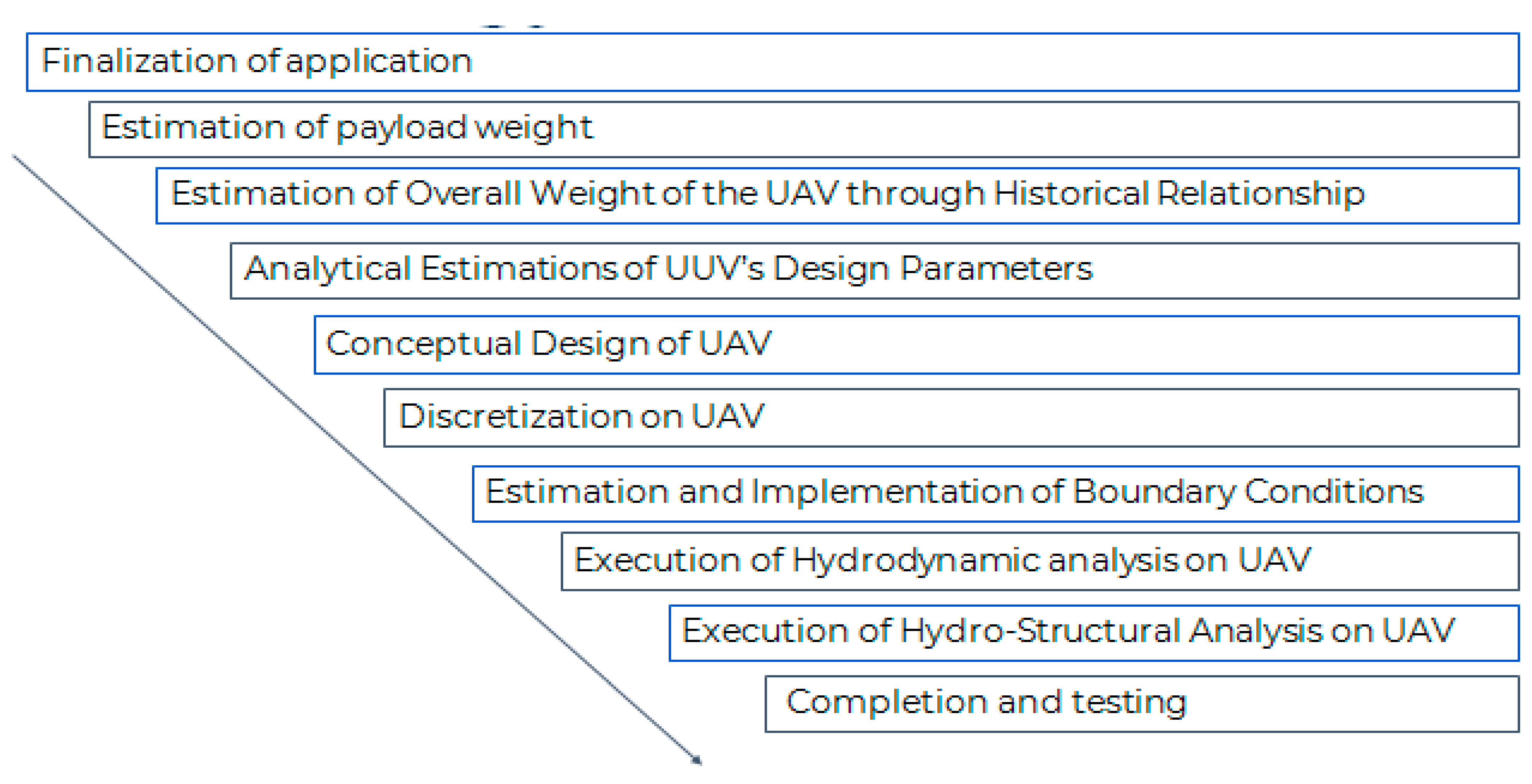
1.1. Aim
1.2. Literature Survey
1.3. Summary
1.4. Symbols and Notations
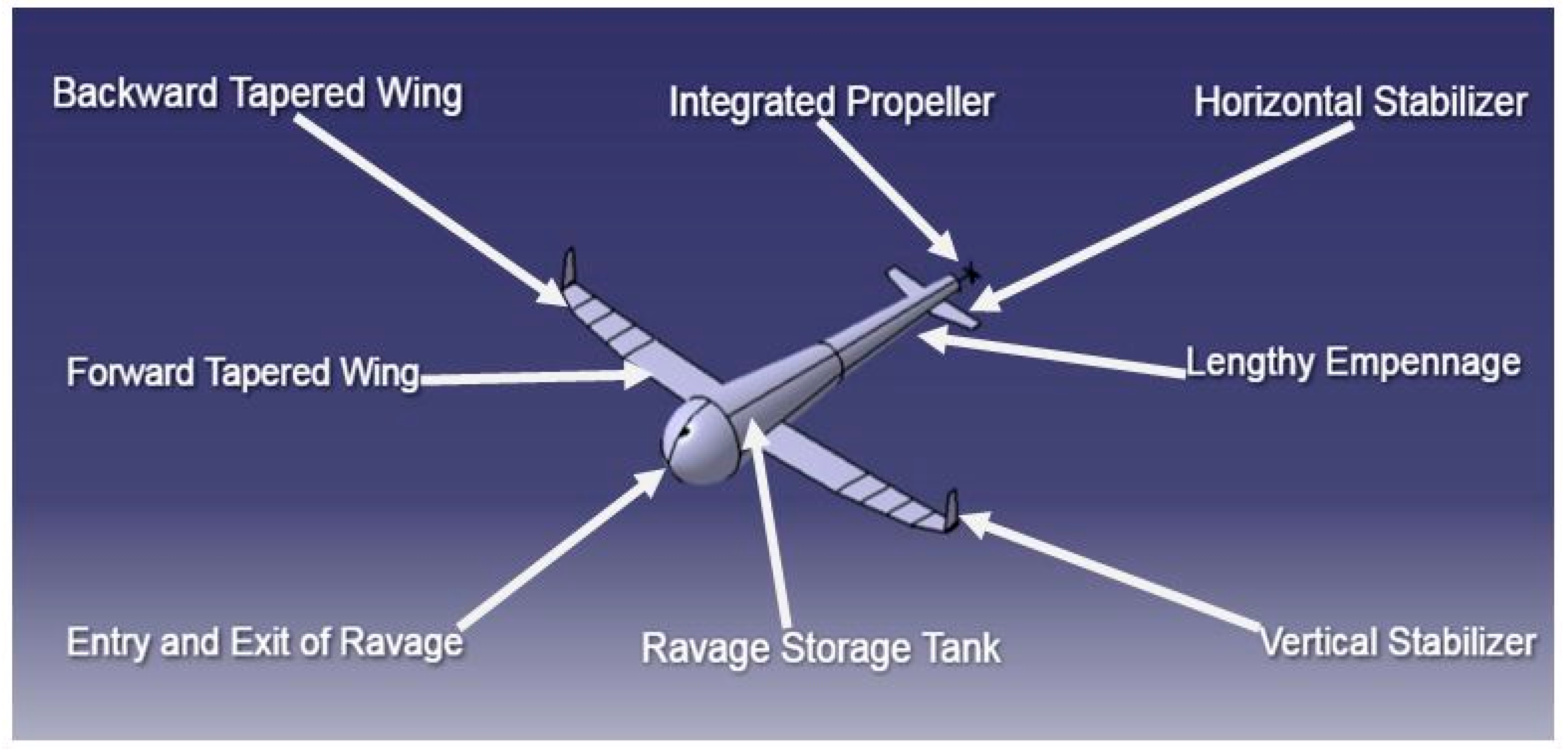
2. Proposed Design—Tropic Bird Inspired UAV
2.1. Design of UAV’s Wing at Aerodynamic Environments
2.1.1. Design of Constant-Chord Swept-Forward (CCSF) Wing
2.1.2. Design of Tapered with Backward Swept Wing
2.2. Design of Wing at Hydrodynamic Environment
Aerofoil Selection for Wing
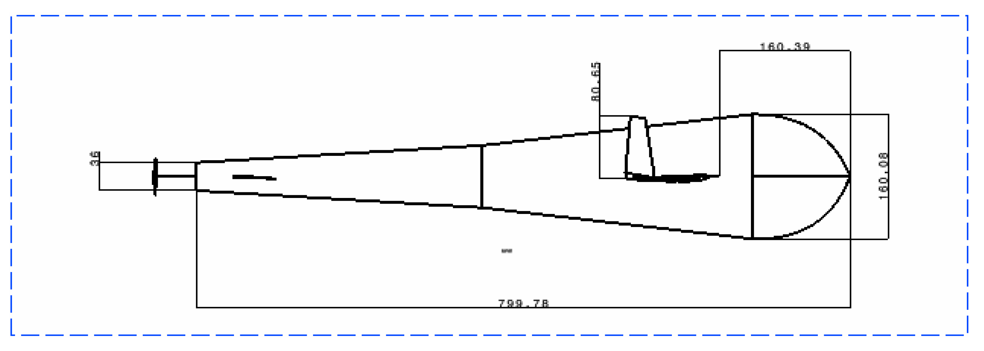
2.3. Design of Fuselage
2.4. Propulsive System Design
2.4.1. Estimation of Pitch Angle and Chord of the Propeller
2.4.2. Aerofoil Selection for Propeller
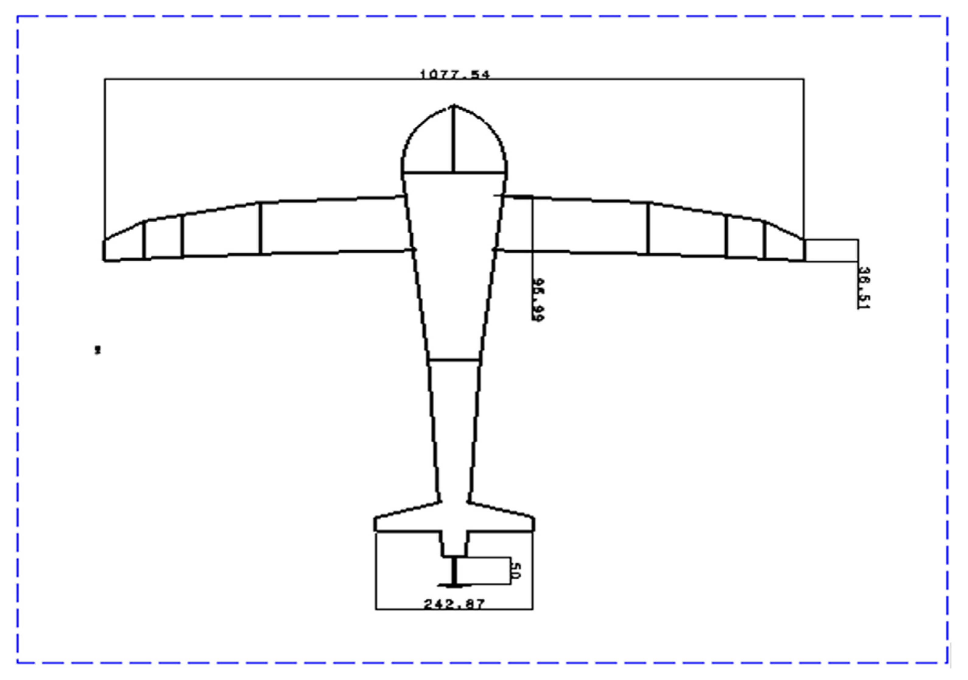
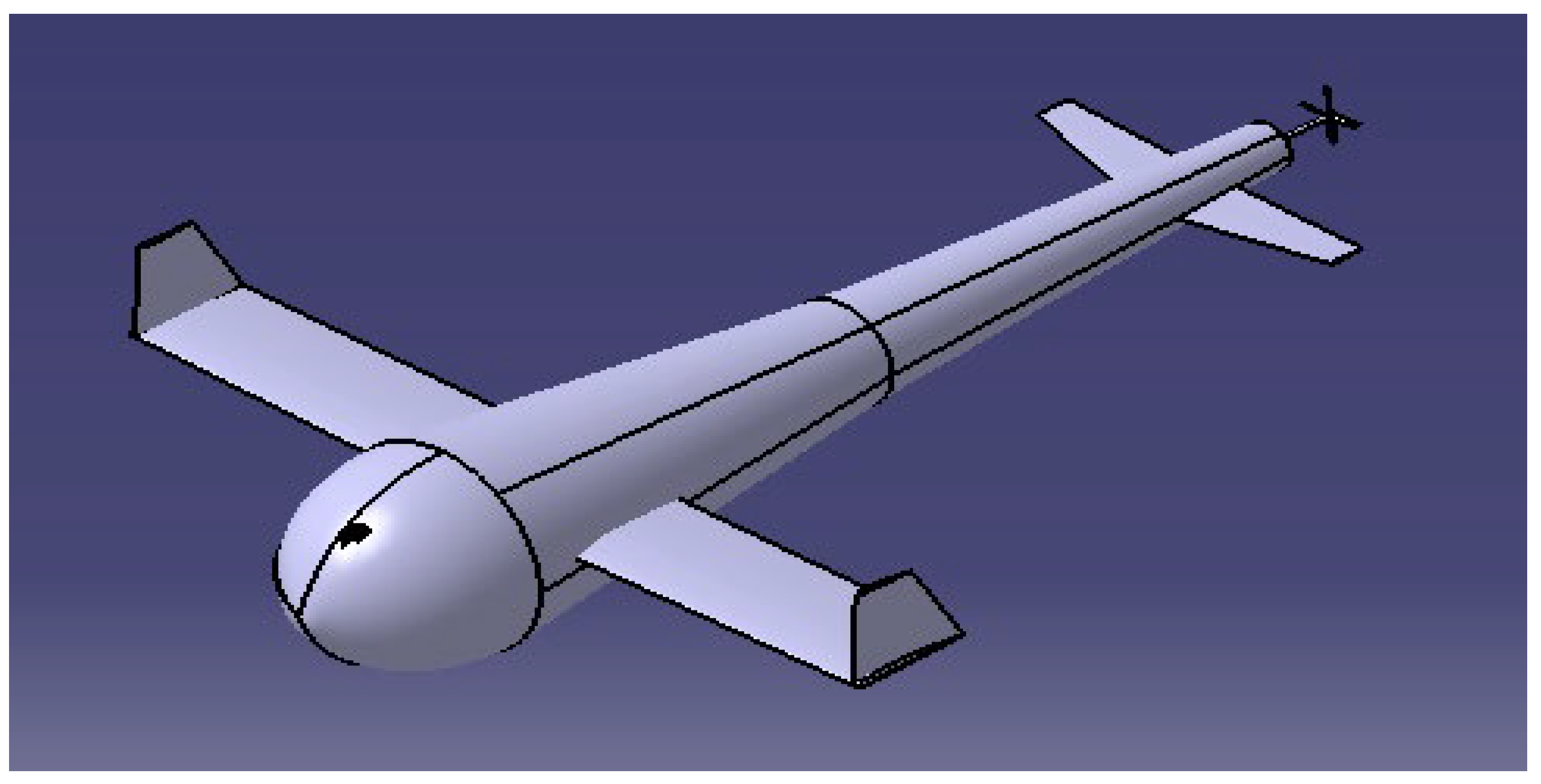
2.5. Design of UAV
3. Proposed Methodology—Advanced Computational Analysis
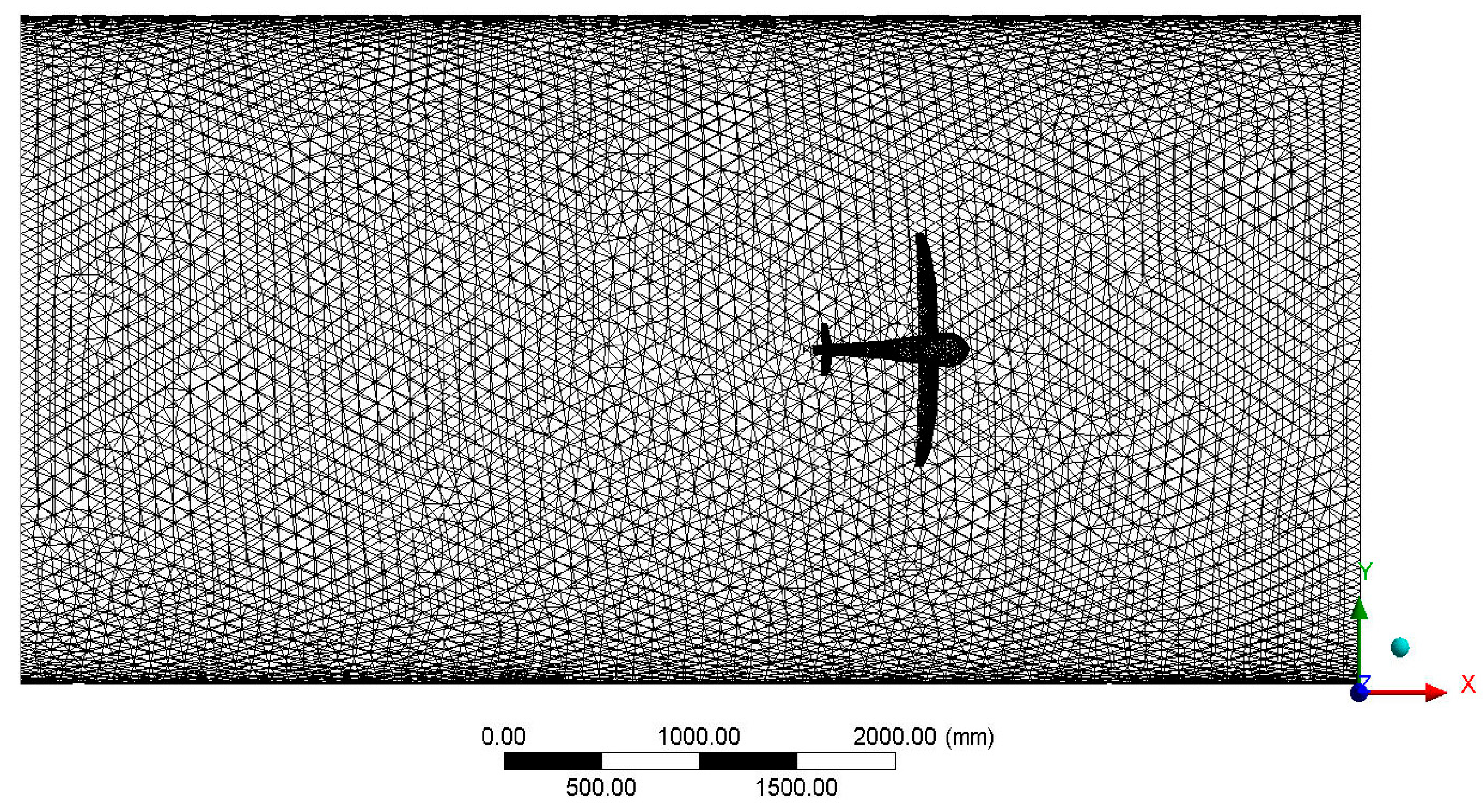
3.1. Computational Aerodynamic and Hydrodynamic Fluid Analyses
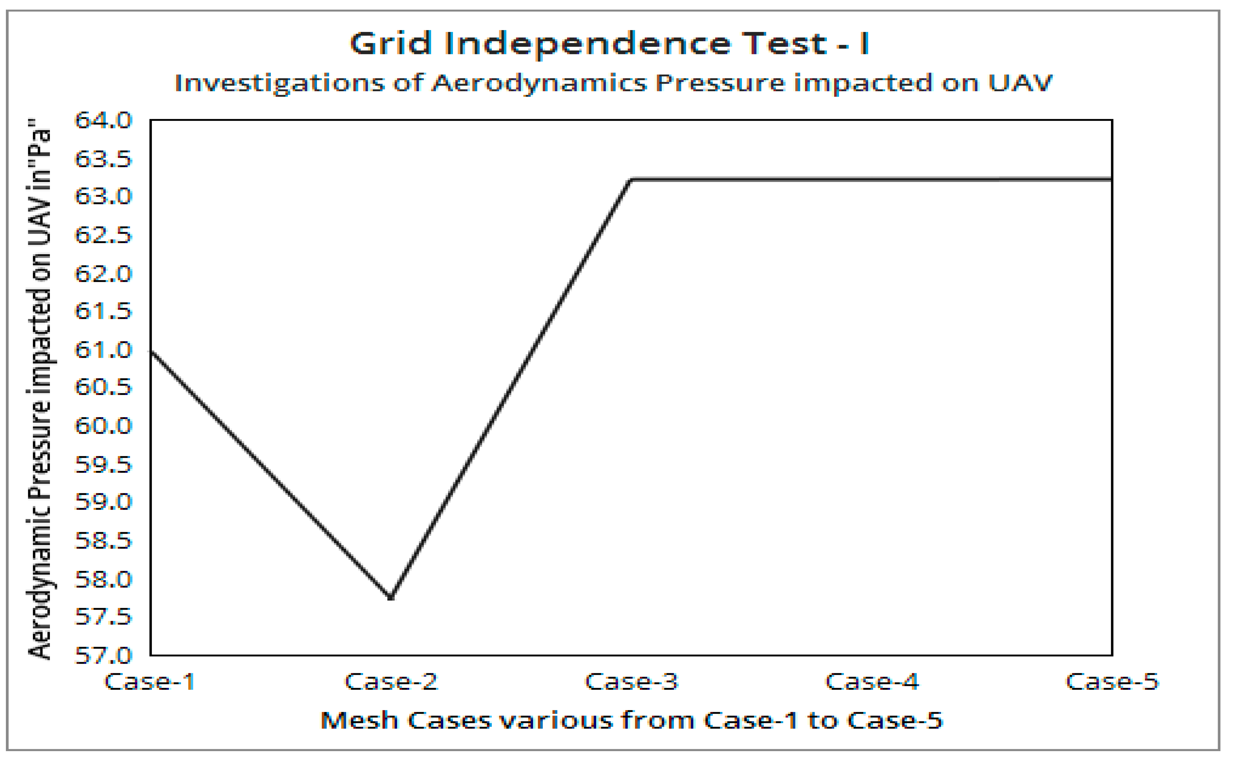
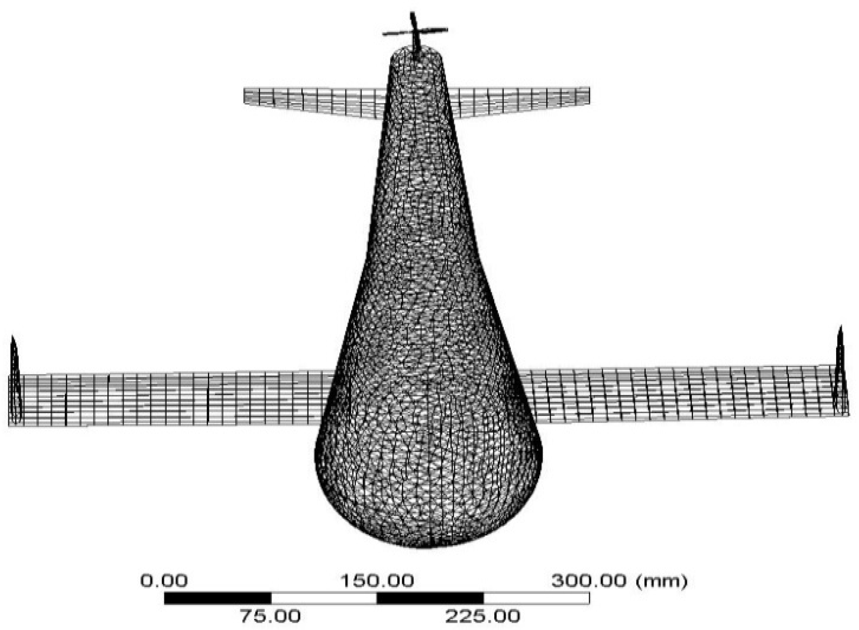
3.1.1. Grid Convergence Study—I
3.1.2. Experimental Validation
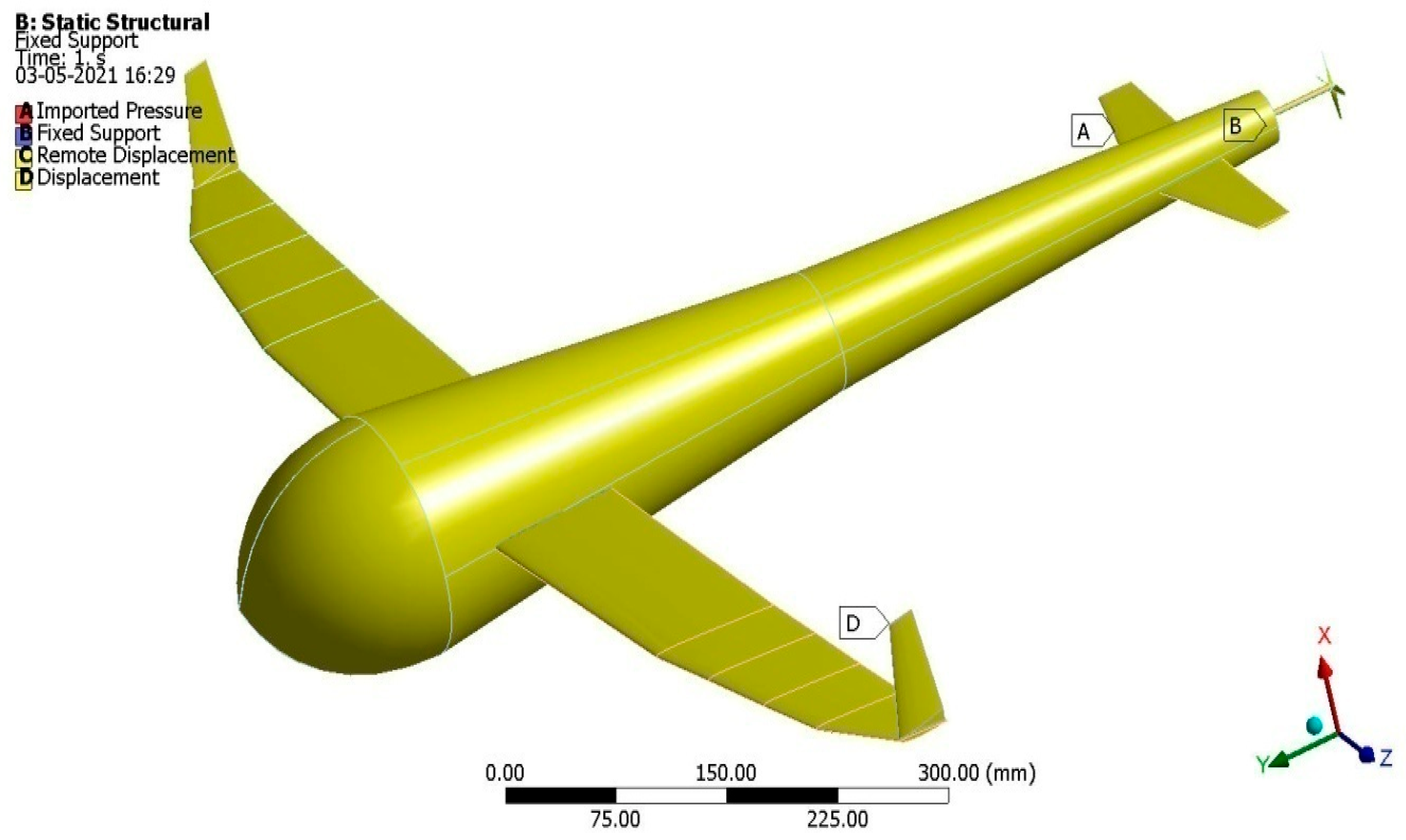
3.2. Computational Aero-Structural and Hydro-Structural Analyses
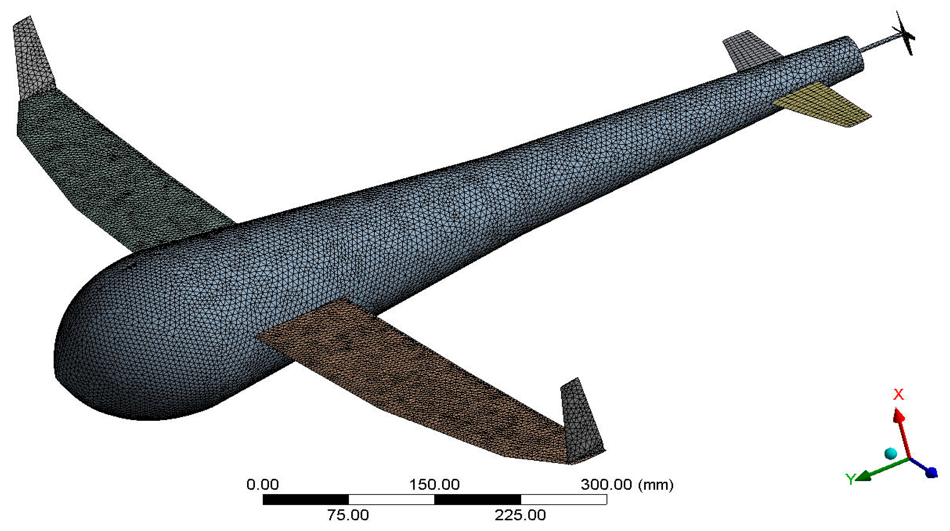
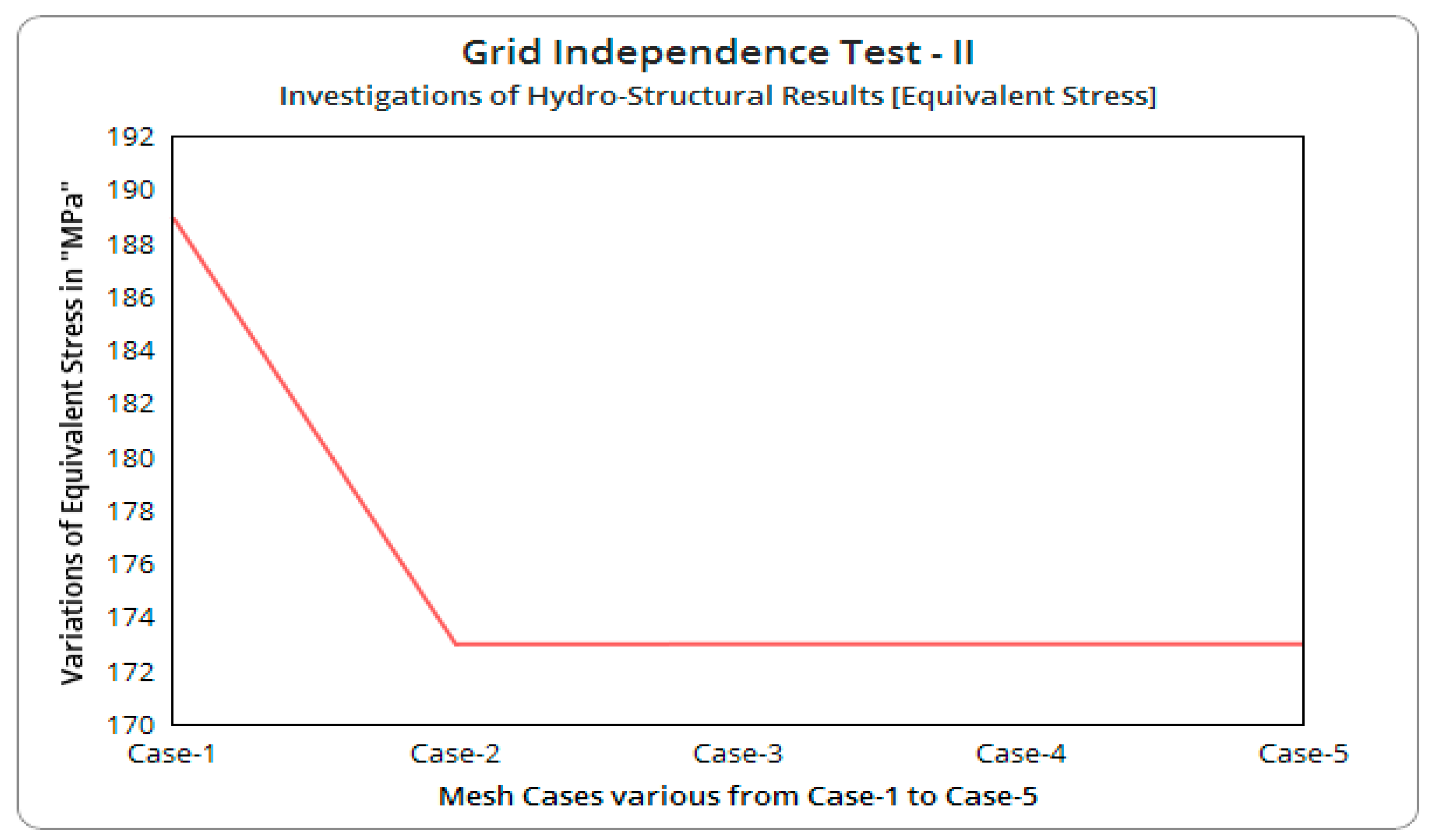
Grid Convergence Study—II
4. Results and Discussions
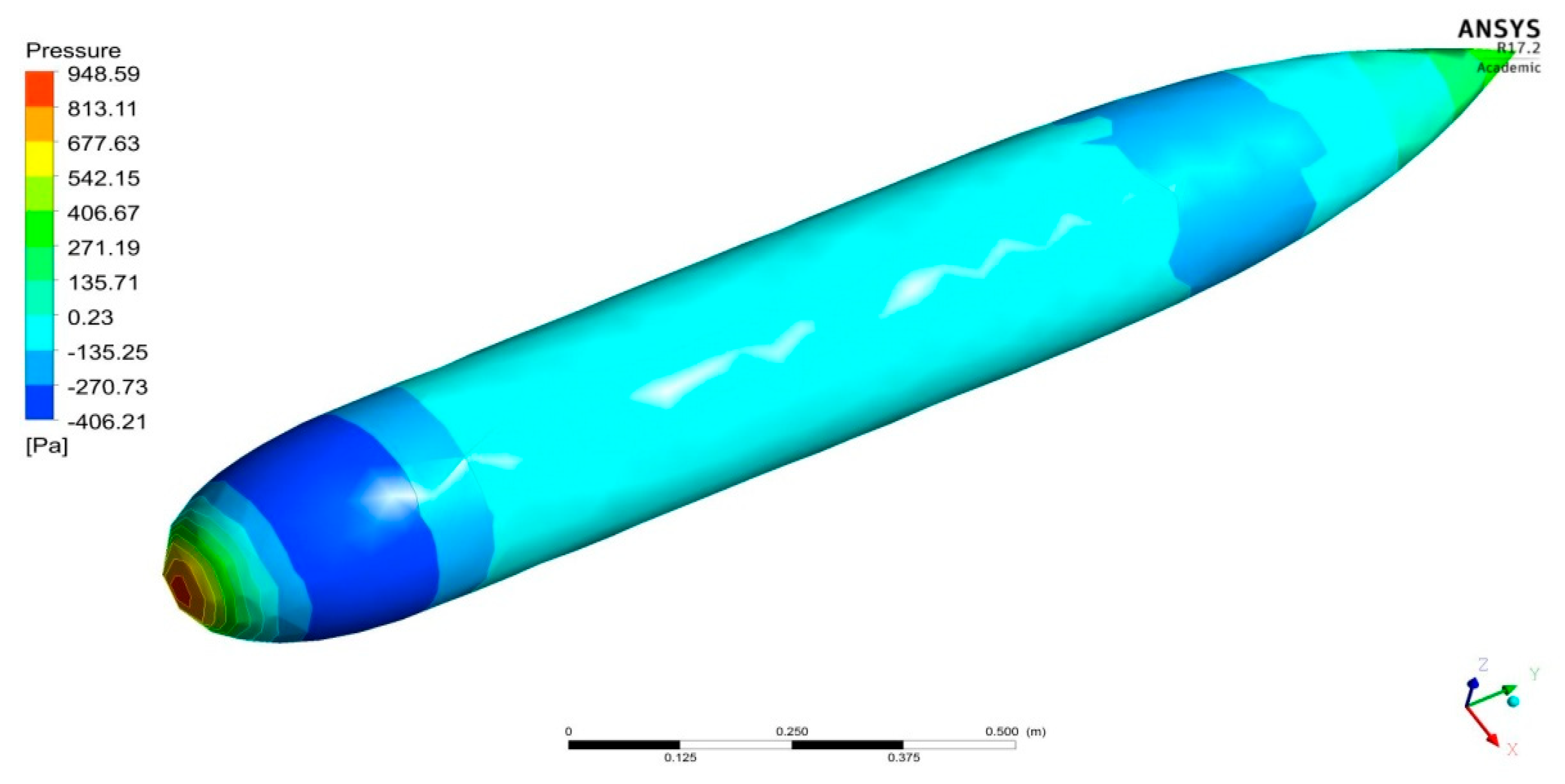
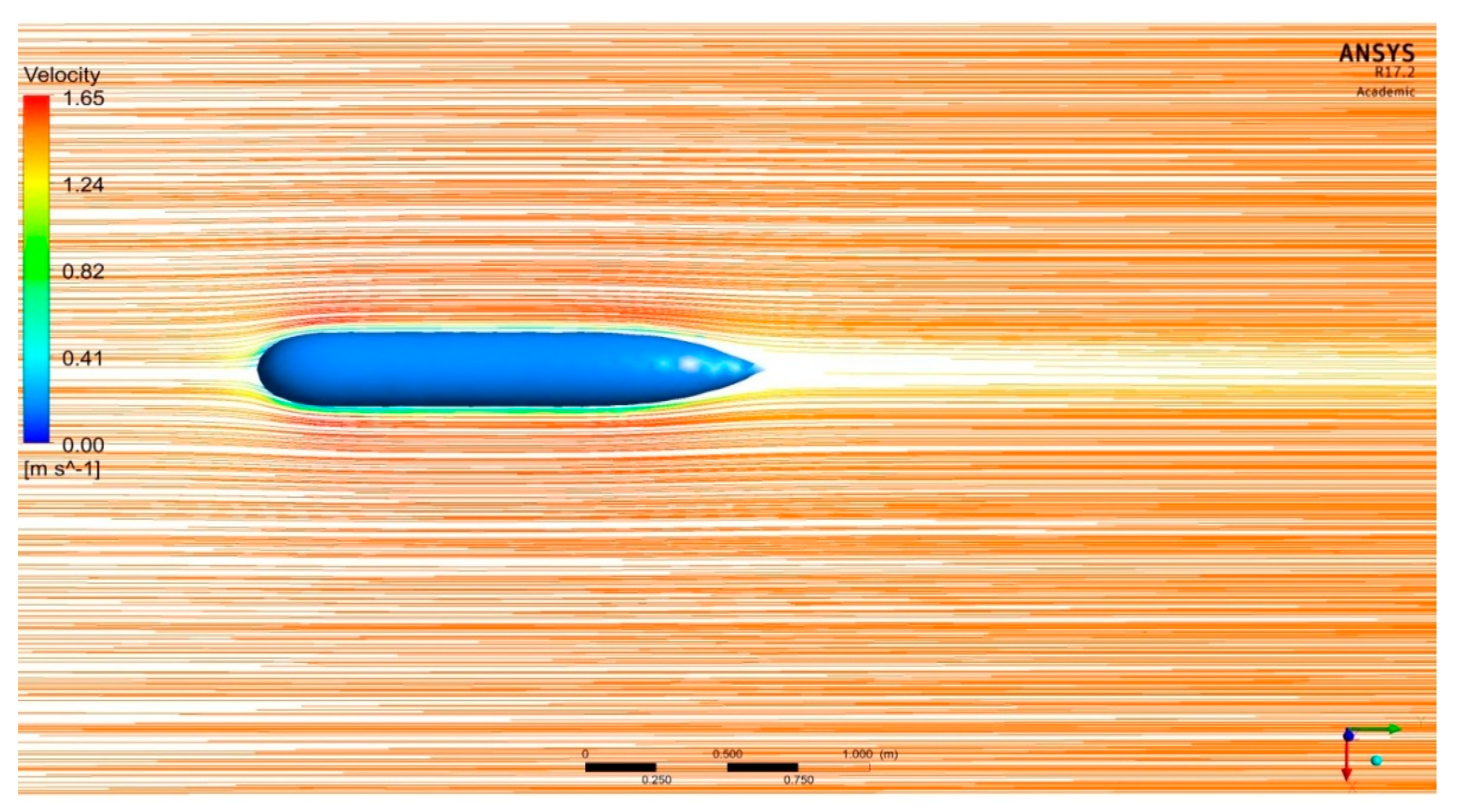
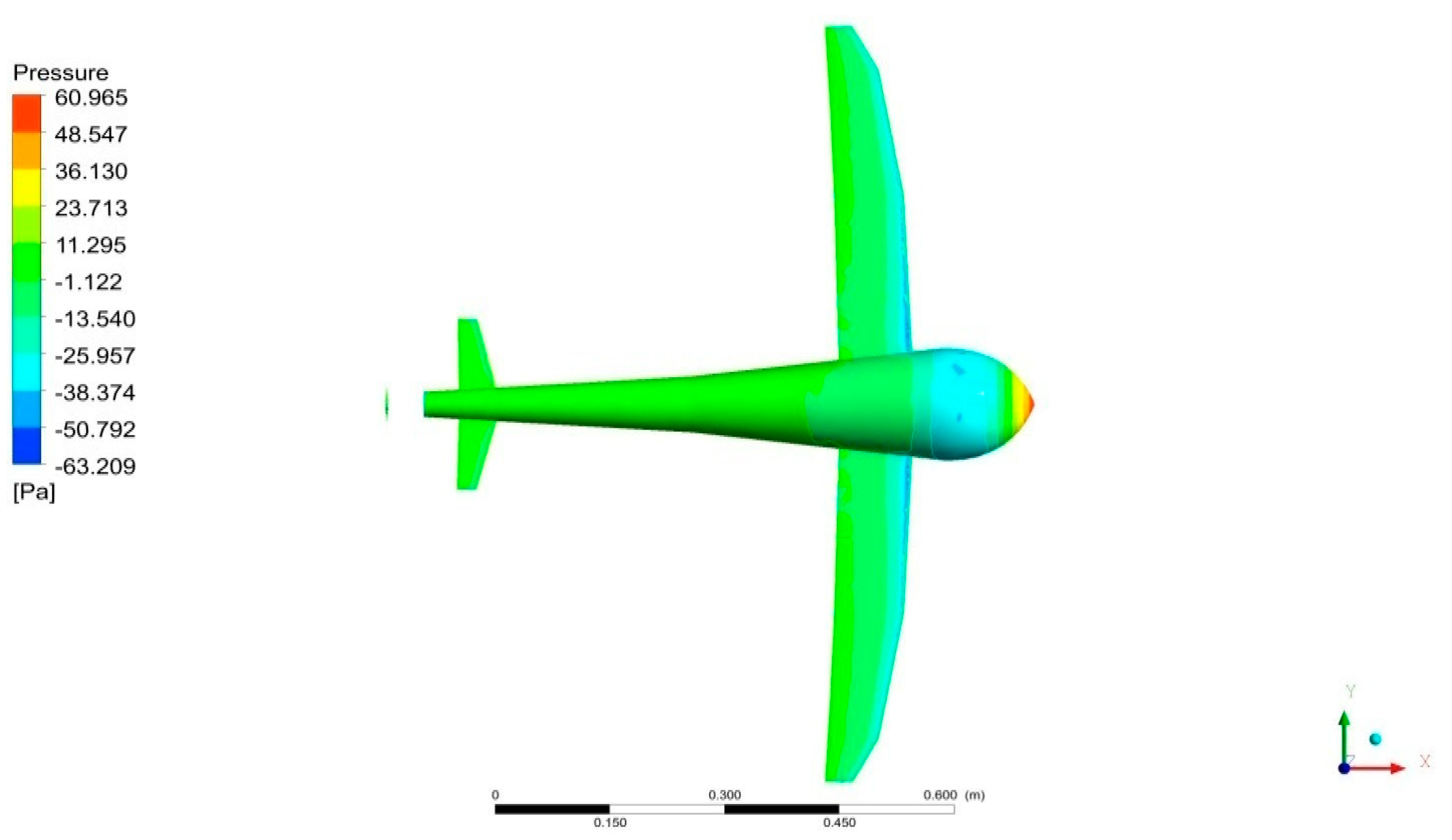
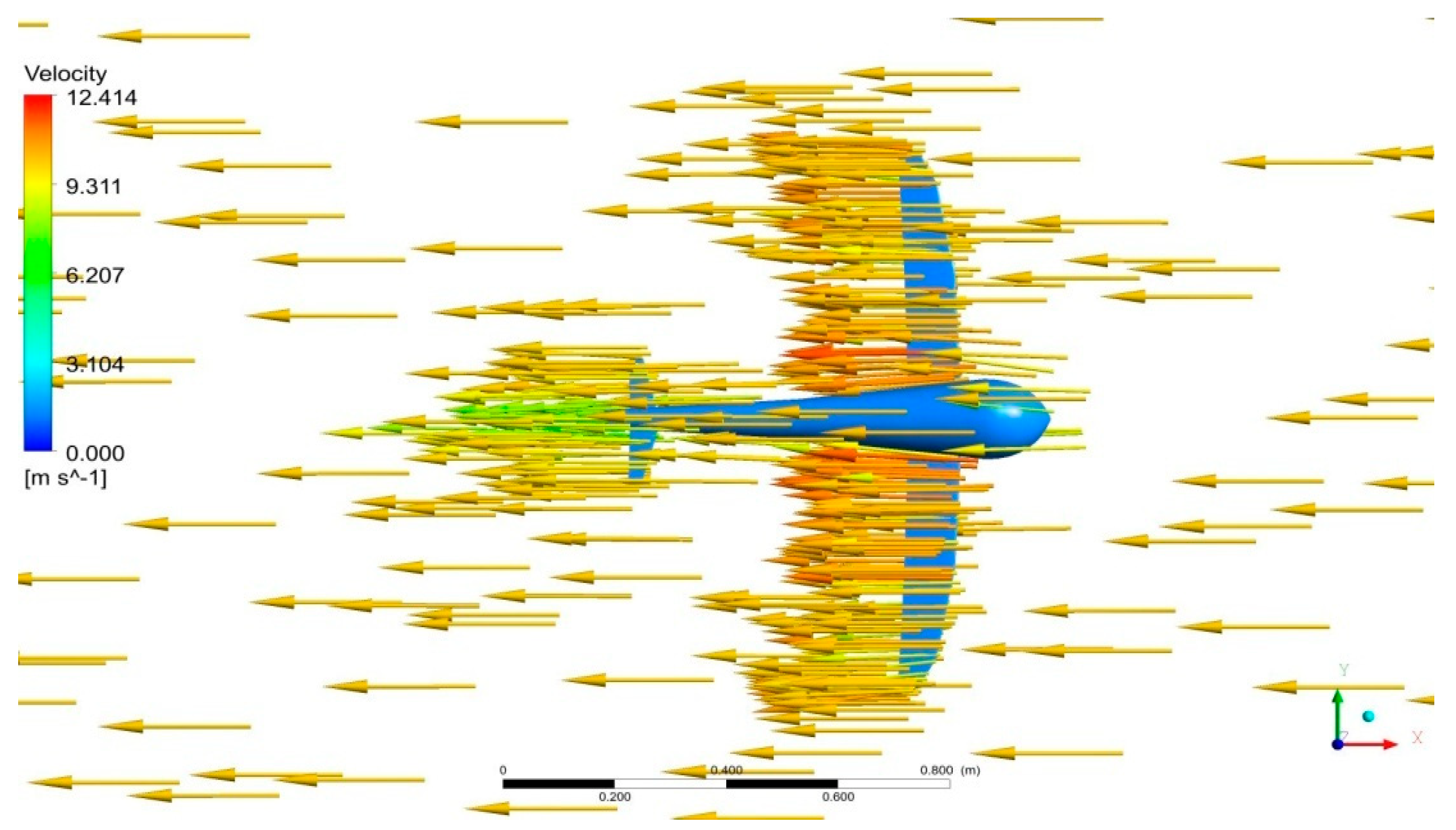
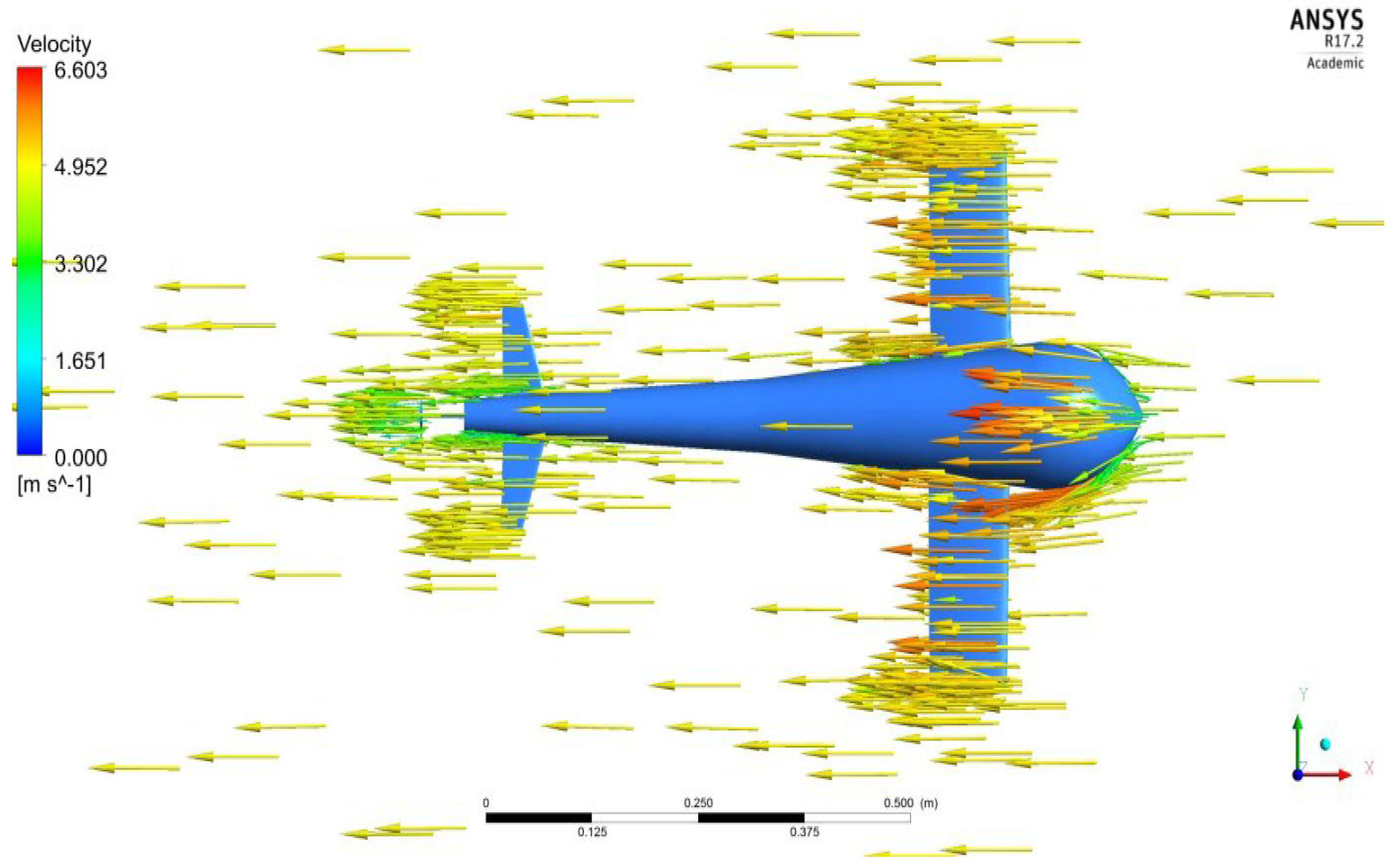
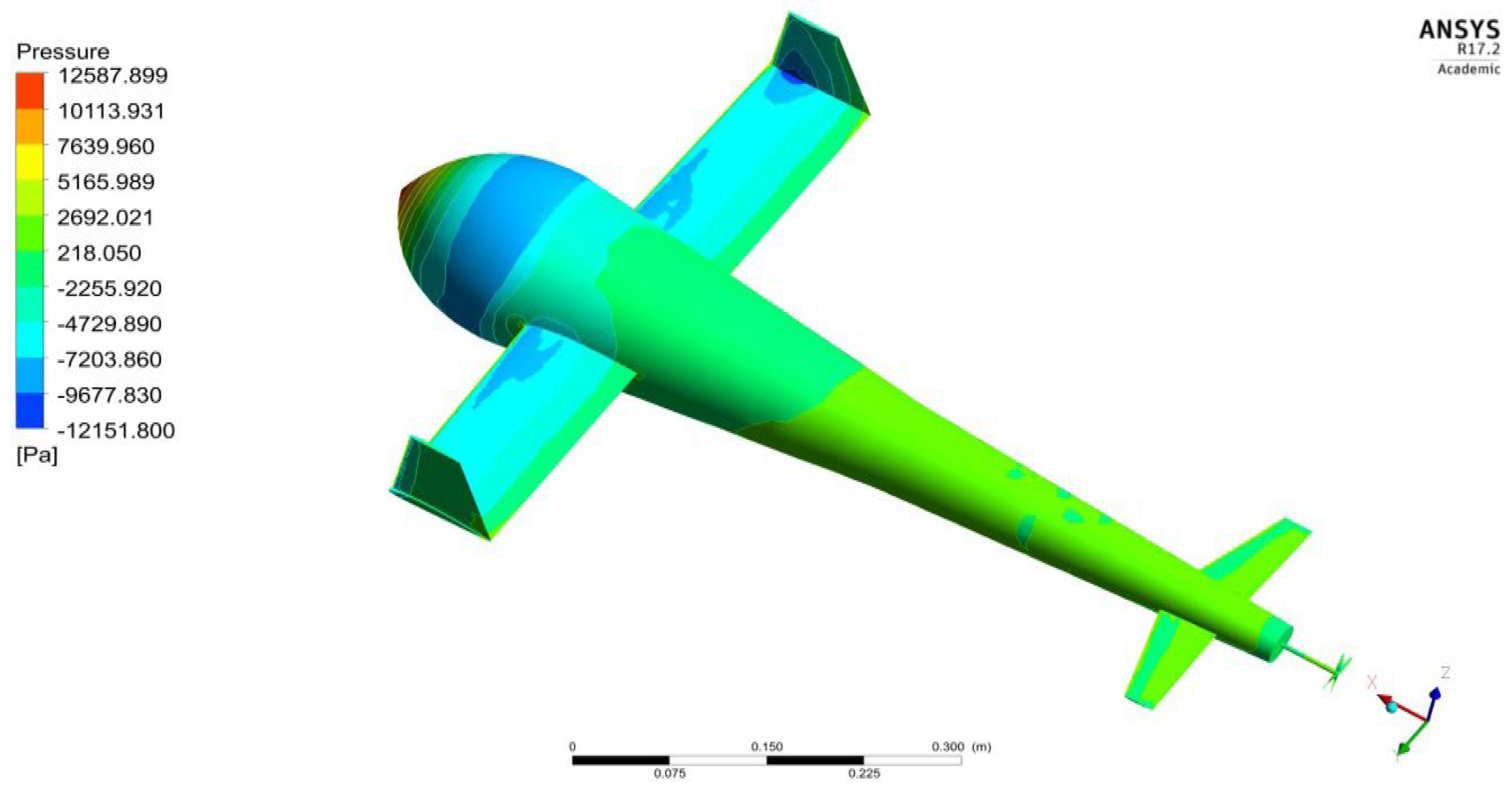
4.1. CFD Results—Above the Surface of Oceans
4.2. HSI Results—Above the Surface of Oceans
4.3. CFD Results—On Surface of the Oceans
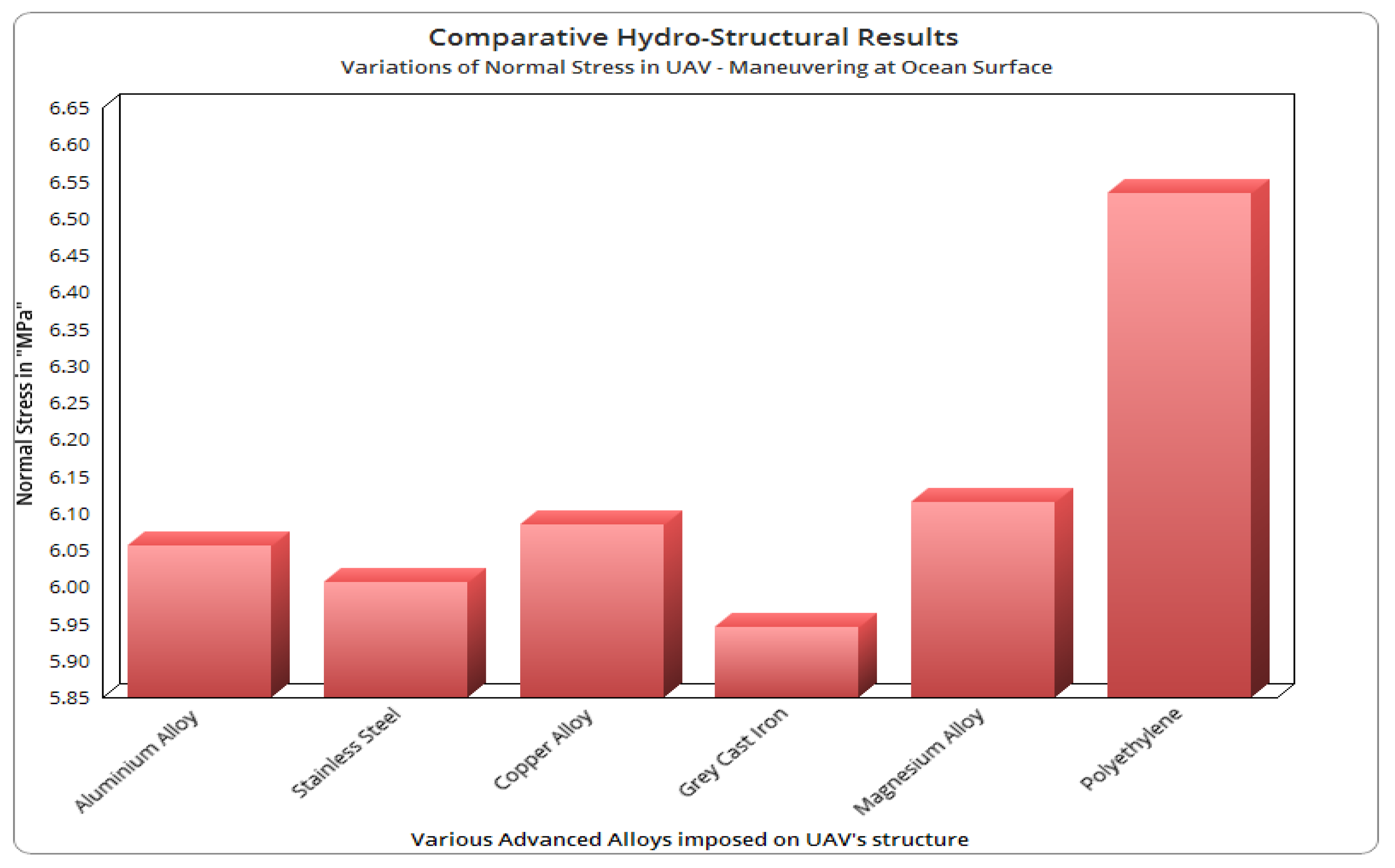
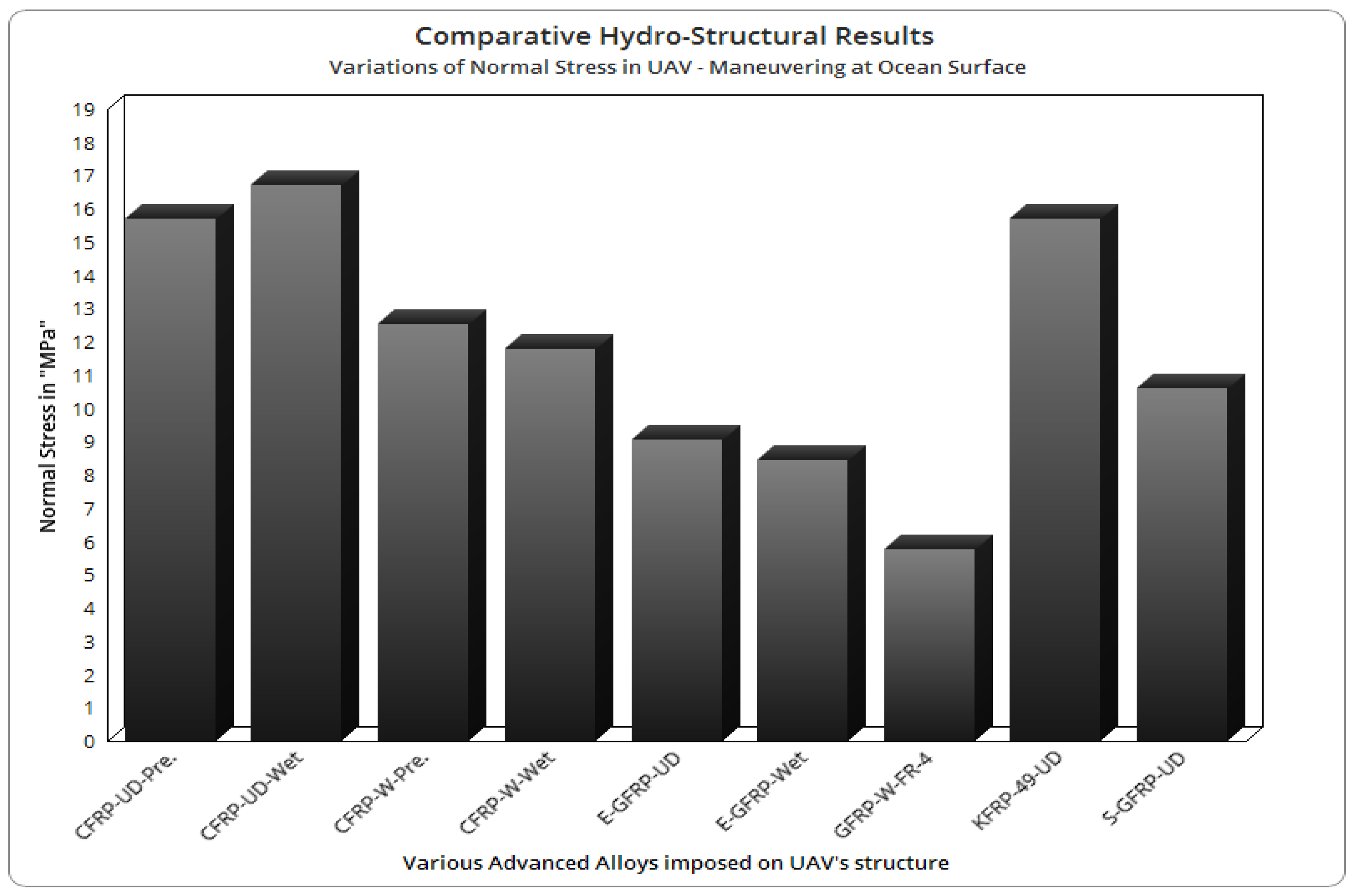
4.4. HSI Results—On Surface of the Oceans
4.5. Final Optimised Design and its CFD Results—Inside the Oceans
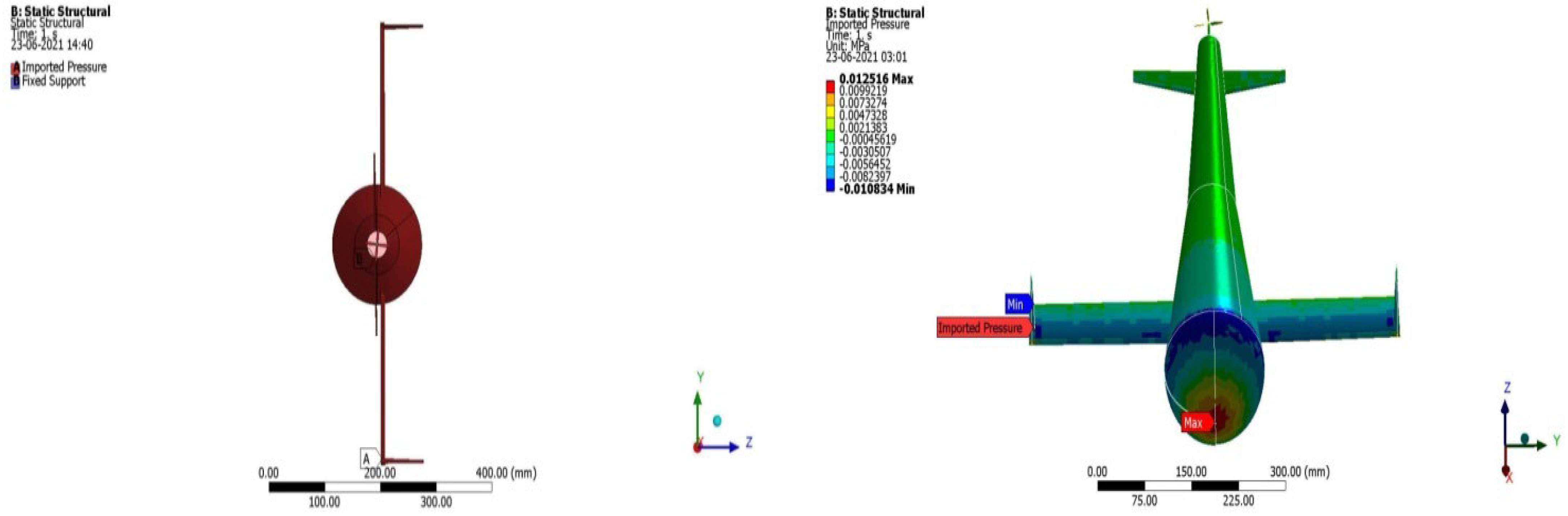
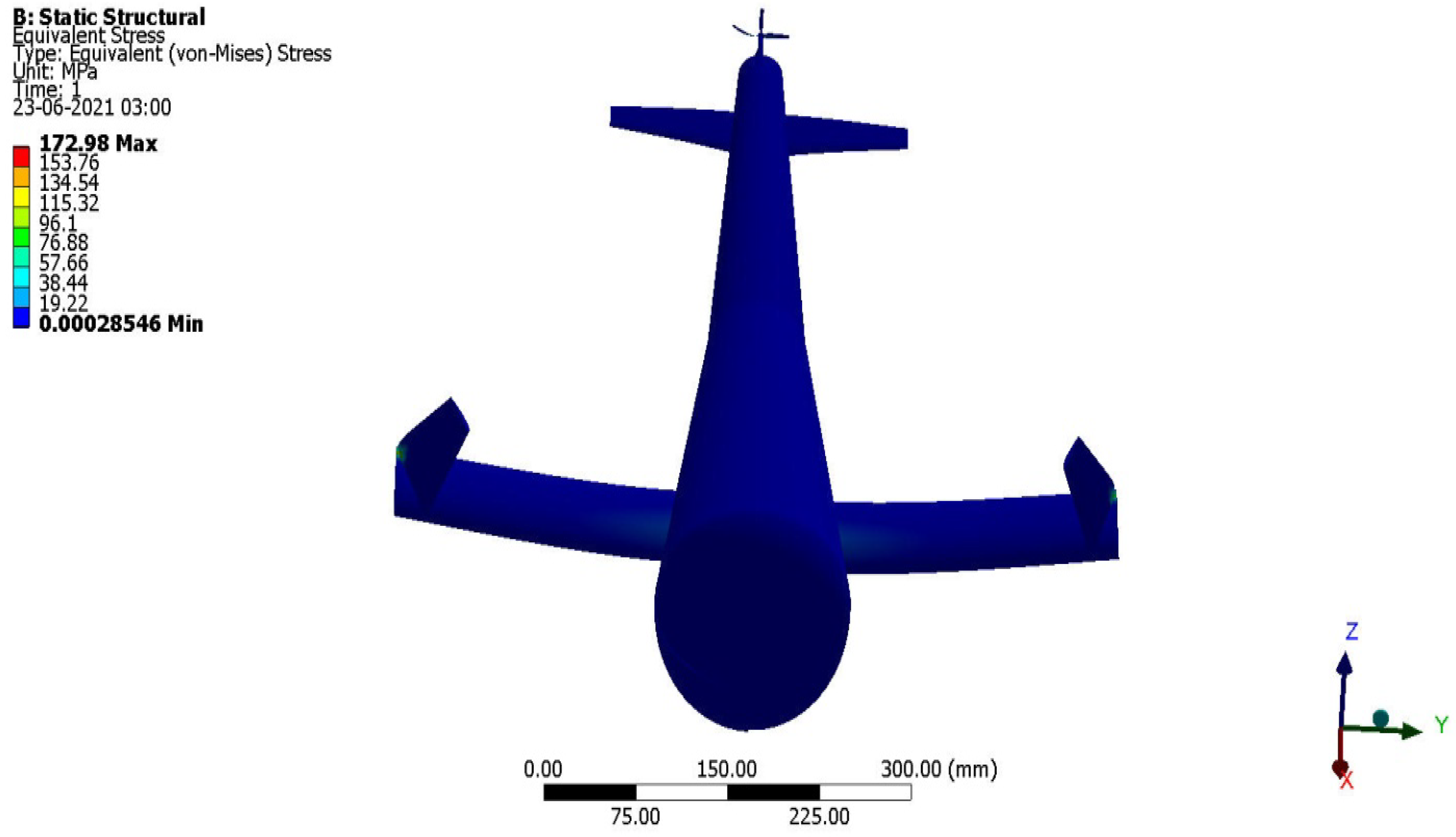
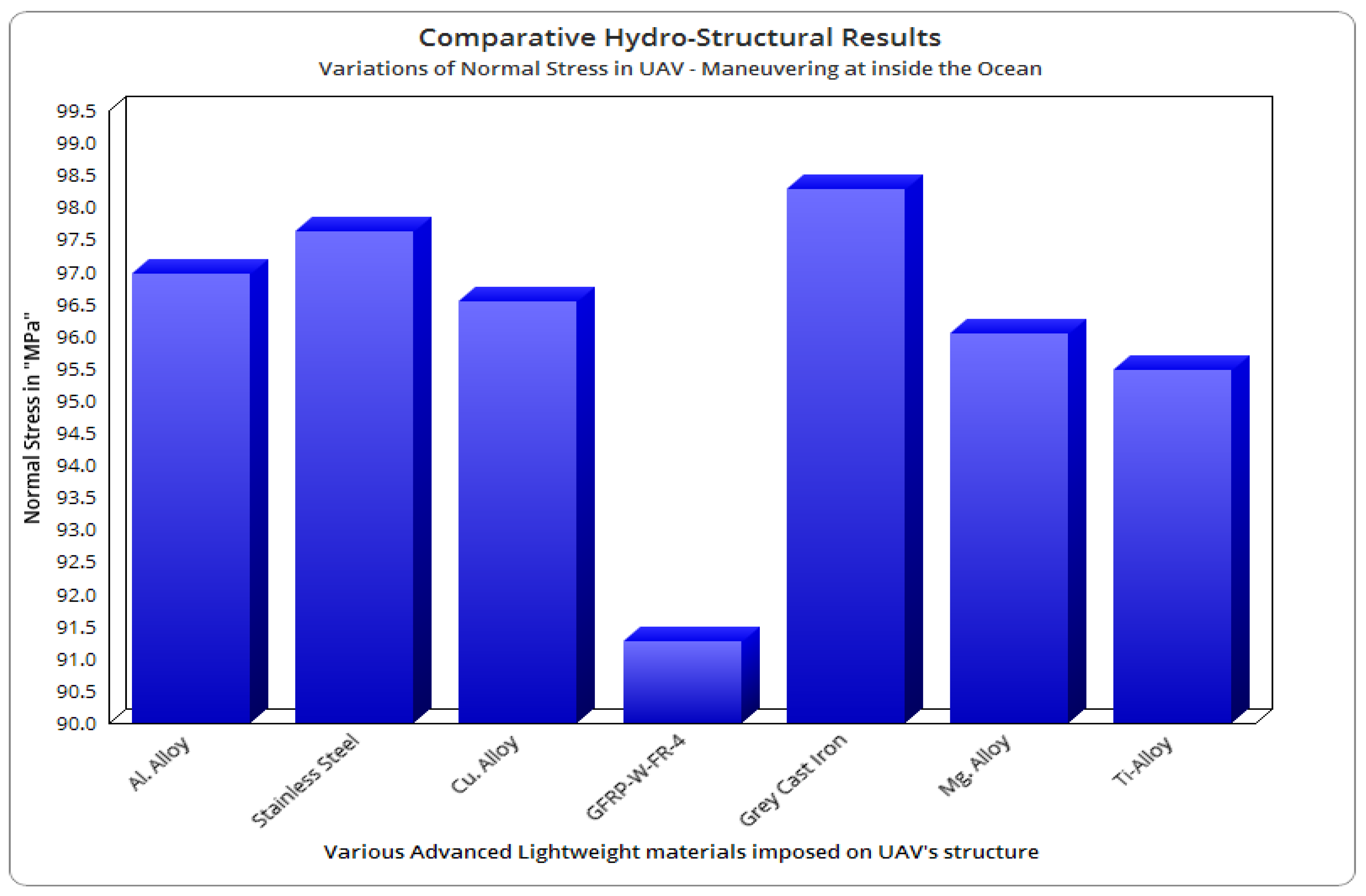
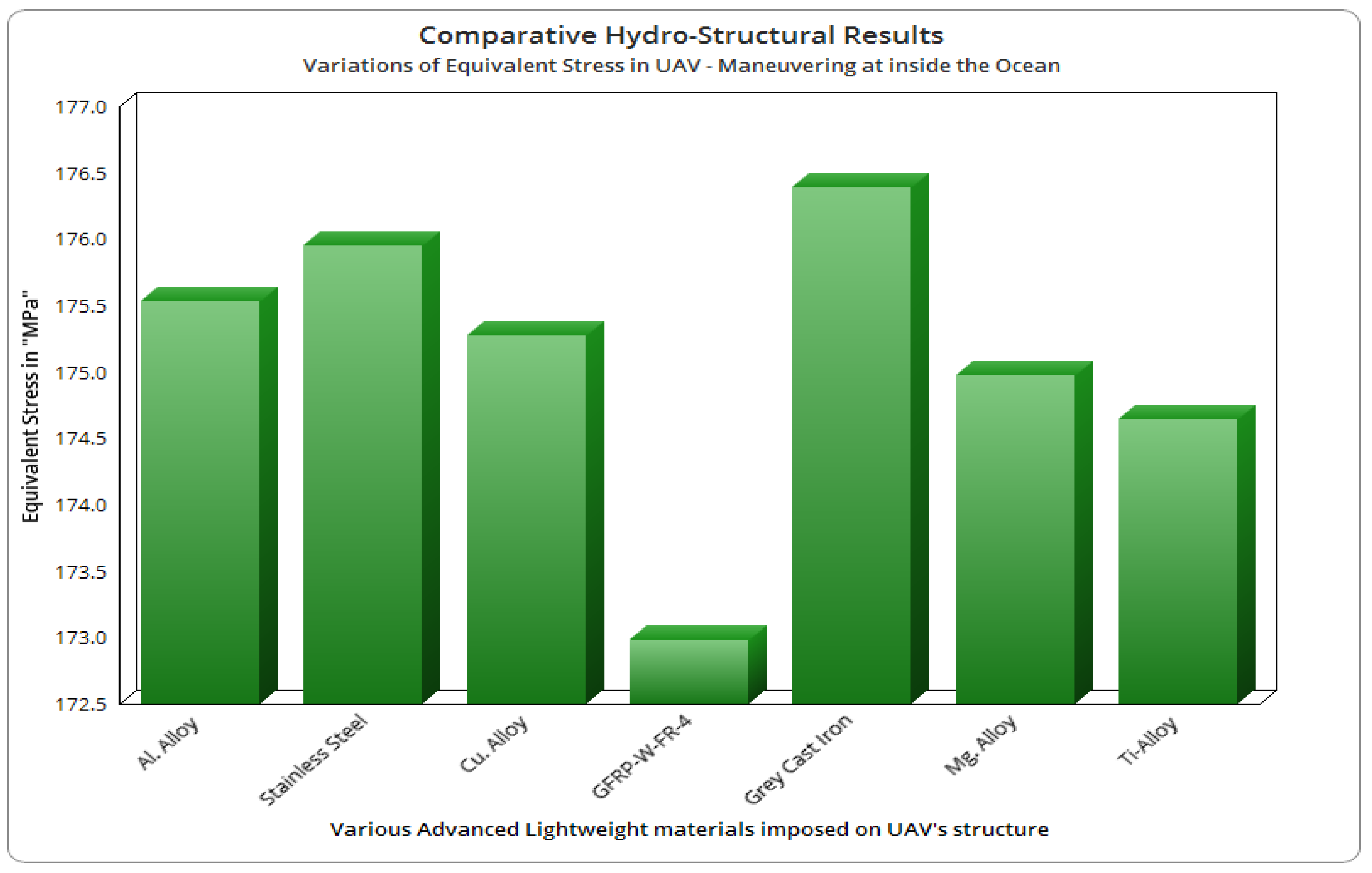
4.6. Final Optimised Design and Its HSI Results—Inside the Oceans
5. Ravage Issue and Its Removal Application
Comprehensive Investigation on Propeller
6. Conclusions
Author Contributions
Funding
Institutional Review Board Statement
Informed Consent Statement
Data Availability Statement
Acknowledgments
Conflicts of Interest
References
- Madasamy, S.K.; Raja, V.; Ganesan, S.; Murugan, D.; Raji, A.P.; Jayaram, D.K. Conceptual Design, and Fluid-Structural Interaction Based Investigations on Highly Maneuverable Unmanned Amphibious Vehicle for Ravage Removal Applications at Various Oceanic Working Environments. Res. Sq. 2021; preprint. [Google Scholar] [CrossRef]
- Wainwright, D.K.; Lauder, G.V. Tunas as a high-performance fish platform for inspiring the next generation of autonomous underwater vehicles. Bioinspir. Biomim. 2020, 15, 035007. [Google Scholar] [CrossRef] [PubMed]
- Bozkurttas, M.; Tangorra, J.; Lauder, G.; Mittal, R. Understanding the Hydrodynamics of Swimming from Fish Fins to Flexible Propulsors for Autonomous Underwater Vehicles. Adv. Sci. Technol. 2008, 58, 193–202. [Google Scholar] [CrossRef]
- Negrello, F.; Silvestri, P.; Lucifredi, A.; Guerrero, J.; Bottaro, A. Preliminary design of a small-sized flapping UAV: II. Kinematic and structural aspects. Meccanica 2015, 51, 1369–1385. [Google Scholar] [CrossRef]
- Joung, T.-H.; Jae-Hwan, L.; Nho, I.; Jong-Moo, L.; Lee, P.-M. A Study on the Structural Design and Analysis of a Deep-sea Unmanned Underwater Vehicle. J. Ocean Eng. Technol. 2006, 20, 7–14. [Google Scholar]
- Wang, Q.; Wu, S.; Hong, W.; Zhuang, W.; Wei, Y. Submersible Unmanned Aerial Vehicle: Configuration Design and Analysis Based on Computational Fluid Dynamics. MATEC Web Conf. 2017, 95, 7023. [Google Scholar] [CrossRef] [Green Version]
- Li, Y.; Hu, J.; Zhao, Q.; Pan, Z.; Ma, Z. Hydrodynamic Performance of Autonomous Underwater Gliders with Active Twin Undulatory Wings of Different Aspect Ratios. J. Mar. Sci. Eng. 2020, 8, 476. [Google Scholar] [CrossRef]
- Tangorra, J.L.; Davidson, S.N.; Hunter, I.W.; Madden, P.G.A.; Lauder, G.V.; Dong, H.; Bozkurttas, M.; Mittal, R. The Development of a Biologically Inspired Propulsor for Unmanned Underwater Vehicles. IEEE J. Ocean. Eng. 2007, 32, 533–550. [Google Scholar] [CrossRef] [Green Version]
- Joung, T.-H.; Sammut, K.; He, F.; Lee, S.-K. Shape optimization of an autonomous underwater vehicle with a ducted propeller using computational fluid dynamics analysis. Int. J. Nav. Arch. Ocean Eng. 2012, 4, 44–56. [Google Scholar] [CrossRef] [Green Version]
- Xuel, G.; Liu, Y.; Chen, Z.; Li, S. Motion Model of Fish-like Underwater Vehicle and its Effect on Hydrodynamic Performance. In Proceedings of the International Symposium on Mechatronics and Its Applications, ISMA, Sharjah, United Arab Emirates, 4–6 March 2018; pp. 1–5. [Google Scholar] [CrossRef]
- Gao, A.; Techet, A.H. Design considerations for a robotic flying fish. In Proceedings of the OCEANS’11 MTS/IEEE KONA, Waikoloa, HI, USA, 19–22 September 2011. [Google Scholar] [CrossRef]
- Zihao, W.; Ye, L.; Aobo, W.; Xiaobing, W. Flying Wing Underwater Glider: Design, Analysis, and Performance Prediction. In Proceedings of the 2015 International Conference on Control, Automation and Robotics, Singapore, 20–22 May 2015. [Google Scholar] [CrossRef]
- Mathaiyan, V.; Murugesan, R.; Madasamy, S.K.; Gnanasekaran, R.K.; Sivalingam, S.; Jung, D.W. Conceptual Design and Numerical analysis of an Unmanned Amphibious Vehicle. In Proceedings of the AIAA 2021-1285 Session: Unmanned Systems IX, Nashville, TN, USA, 11–15 & 19–21 January 2021. [Google Scholar] [CrossRef]
- Javaid, M.Y.; Ovinis, M.; Hashim, F.B.; Maimun, A.; Ahmed, Y.M.; Ullah, B. Effect of wing form on the hydrodynamic characteristics and dynamic stability of an underwater glider. Int. J. Nav. Arch. Ocean Eng. 2017, 9, 382–389. [Google Scholar] [CrossRef] [Green Version]
- Alam, K.; Ray, T.; Anavatti, S.G. An Evolutionary Approach for the Design of Autonomous Underwater Vehicles. In Proceedings of the 25th Australasian Joint Conference on Advances in Artificial Intelligence (AI 2012), Sydney, NSW, Australia, 2–4 February 2022; LNCS 7691. pp. 279–290. [Google Scholar] [CrossRef]
- Kumar, V.P.; Kumar, S.K.; Pandian, K.S.; Ashraf, E.; Selvan, K.T.T.; Vijayanandh, R. Conceptual Design And Hydrodynamic Research On Unmanned Aquatic Vehicle. Int. J. Innov. Technol. Explor. Eng. 2019, 8, 121–127. [Google Scholar]
- Wadoo, S.; Kachroo, P. Autonomous Underwater Vehicles. Modeling, Control Design, and Simulation; Taylor and Francis Group, LLC: Abingdon, UK, 2011. [Google Scholar]
- Costa, D.; Palmieri, G.; Palpacelli, M.-C.; Panebianco, L.; Scaradozzi, D.; Costa, D. Design of a Bio-Inspired Autonomous Underwater Robot. J. Intell. Robot. Syst. 2017, 91, 181–192. [Google Scholar] [CrossRef]
- Wood, S. Autonomous Underwater Gliders, Underwater Vehicles Book; Intech: London, UK, 2009. [Google Scholar] [CrossRef] [Green Version]
- Eichhorn, M.; Ament, C.; Jacobi, M.; Pfuetzenreuter, T.; Karimanzira, D.; Bley, K.; Boer, M.; Wehde, H. Modular AUV System with Integrated Real-Time Water Quality Analysis. Sensors 2018, 18, 1837. [Google Scholar] [CrossRef] [PubMed] [Green Version]
- Vasudev, K.L. Review of Autonomous Underwater Vehicles, Autonomous Vehicles Book; Intech: London, UK, 2018. [Google Scholar] [CrossRef]
- Amin, O.M.; Karim, A.; Saad, A.H. Development of a highly maneuverable unmanned underwater vehicle on the basis of quad-copter dynamics. AIP Conf. Proc. 2017, 1919, 020009. [Google Scholar] [CrossRef] [Green Version]
- Pandian, R.S.; Vijayanandh, R.; Kumar, S.K.; Kumar, V.P.; Ramesh, M.; Kumar, M.S.; Kumar, G.R. Comparative Hydrodynamic Investigations on Unmanned Aquatic Vehicle for Ocean Applications. In Lecture Notes in Mechanical Engineering Book Series (LNME); Springer: Singapore, 2021; ISBN 978-981-16-2086-7. [Google Scholar] [CrossRef]
- Nesteruk, I.; Passoni, G.; Redaelli, A. Shape of Aquatic Animals and Their Swimming Efficiency. J. Mar. Biol. 2014, 2014, 470715. [Google Scholar] [CrossRef] [Green Version]
- Bettle, M.C.; Gerber, A.G.; Watt, G.D. Using reduced hydrodynamic models to accelerate the predictor–corrector convergence of implicit 6-DOF URANS submarine manoeuvring simulations. Comput. Fluids 2014, 102, 215–236. [Google Scholar] [CrossRef] [Green Version]
- Hamidi, A.; Almubarak, Y.; Rupawat, Y.M.; Warren, J.; Tadesse, Y. Poly-Saora robotic jellyfish: Swimming underwater by twisted and coiled polymer actuators. Smart Mater. Struct. 2020, 29, 045039. [Google Scholar] [CrossRef]
- Wang, Y.; Zhang, Y.; Zhang, M.; Yang, Z.; Wu, Z. Design and flight performance of hybrid underwater glider with controllable wings. Int. J. Adv. Robot. Syst. 2017, 14, 1729881417703566. [Google Scholar] [CrossRef] [Green Version]
- Alam, K.; Ray, T.; Anavatti, S.G. Design and construction of an autonomous underwater vehicle. Neurocomputing 2014, 142, 16–29. [Google Scholar] [CrossRef]
- Budiyono, A. Advances in unmanned underwater vehicles technologies: Modeling, control and guidance perspectives. Indian J. Geo-Mar. Sci. 2009, 38, 282–295. [Google Scholar]
- Cui, W.; Suming, Q.; Weicheng, C. An Overview on Aquatic Unmanned Aerial Vehicles. Ann. Rev. Res. 2019, 5, 555663. [Google Scholar] [CrossRef]
- Garibal, S.B. Mechanical Design for a New Autonomous Underwater Vehicle (AUV); Project Report; The NPS Institutional Archive: Calhoun, Georgia, 1999; Available online: http://hdl.handle.net/10945/810 (accessed on 14 September 2022).
- Hyakudome, T. Design of Autonomous Underwater Vehicle. Int. J. Adv. Robot. Syst. 2011, 8, 122–130. [Google Scholar]
- Wang, Y.-L.; Tai, C.-H.; Huang, H.-R. Design and development of an autonomous underwater vehicle—Robot dolphin. J. Mar. Eng. Technol. 2015, 14, 44–55. [Google Scholar] [CrossRef] [Green Version]
- Wang, Z.-J.; Nie, Z.-Q.; Li, J.-X.; Ma, Y. Conceptual Design of a Water-air Amphibious Unmanned Vehicle. DEStech Trans. Comput. Sci. Eng. 2019. [Google Scholar] [CrossRef]
- Uiblein, F. Deep-Sea Fish Behavioral Responses to Underwater Vehicles: Differences among Vehicles, Habitats and Species, Autonomous Underwater Vehicles; Cruz, N., Ed.; IntechOpen Limited: London, UK, 2011; ISBN 978-953-307-432-0. [Google Scholar] [CrossRef] [Green Version]
- Fish, F.E. Wing design and scaling of flying fish with regard to flight performance. J. Zool. 1990, 221, 391–403. [Google Scholar] [CrossRef]
- Wang, J.; Wainwright, D.K.; Lindengren, R.E.; Lauder, G.V.; Dong, H. Tuna locomotion: A computational hydrodynamic analysis of finlet function. J. R. Soc. Interface 2020, 17, 20190590. [Google Scholar] [CrossRef] [Green Version]
- Ignacio, L.C.; Victor, R.R.; Francisco, D.R.R.; Pascoal, A. Optimized design of an autonomous underwater vehicle, for exploration in the Caribbean Sea. Ocean Eng. 2019, 187, 106184. [Google Scholar] [CrossRef]
- Park, H.; Choi, H. Aerodynamic characteristics of flying fish in gliding flight. J. Exp. Biol. 2010, 213, 3269–3279. [Google Scholar] [CrossRef] [Green Version]
- Allotta1, B.; Costanzi1, R.; Monni, N.; Pugi, L.; Ridolfi, A.; Vettori, G. Design And Simulation of An Autonomous Underwater vehicle. In Proceedings of the ECCOMAS 2012, Vienna, Austria, 10–14 September 2012. [Google Scholar]
- Kulandaiyaappan, N.K.; Gnanasekaran, R.K.; Raja, V.; Bernard, F.A.; Murugesan, R.; Madasamy, S.K.; Mathaiyan, V.; Raji, A.P.; KAsher, P.; Ponmariappan, J. Optimization of High Payload Unmanned Aerial Vehicle’s Propellers based on Energy Formation by using Computational Vibrational Analyses. In Proceedings of the AIAA Propulsion and Energy 2021 Forum, Virtual, 9–11 August 2021. [Google Scholar] [CrossRef]
- Du, X.-X.; Wang, H.; Hao, C.-Z.; Li, X.-L. Analysis of hydrodynamic characteristics of unmanned underwater vehicle moving close to the sea bottom. Def. Technol. 2014, 10, 76–81. [Google Scholar] [CrossRef]
- Raja, V.; Gnanasekaran, R.K.; Rajendran, P.; Mohd Ali, A.; Rasheed, R.; AL-bonsrulah, H.A.Z.; Al-Bahrani, M. Asymmetrical Damage Aspects Based Investigations on the Disc Brake of Long-Range UAVs through Verified Computational Coupled Approaches. Symmetry 2022, 14, 2035. [Google Scholar] [CrossRef]
- Vijayanandh, R.; Senthilkumar, S.; Rajkumar, R.; Kumar, A.; Kumar, M.S.; Kumar, J.D.; Kumar, K.K.; Prakash, R.A. Conceptual design and computational investigations of fixed wing unmanned aerial vehicle for medium-range applications. In Autonomous and Connected Heavy Vehicle Technology, 1st ed.; Academic Press: Cambridge, MA, USA, 2022; pp. 353–374. [Google Scholar] [CrossRef]
- Raja, V.; Samy, M.; Nachimuthu, K.; Sathyamoorthy, S.; Krishnasamy, D.; Raji, A.P.; Gnanasekaran, R.K.; Madasamy, S.K.; Kulandaiyappan, N.K.; Mathaiyan, V.; et al. Material Optimizations on UAV’s axial flow compressor blade by using FSI Approach. In Proceedings of the AIAA SCITECH 2022 Forum, San Diego, CA, USA, 3–7 January 2022. [Google Scholar] [CrossRef]
- Gudmundsson, S. The Anatomy of the Wing, General Aviation Aircraft Design, Butterworth-Heinemann; Elsevier: Amsterdam, The Netherlands, 2014; Chapter 9; pp. 299–399. ISBN 9780123973085. [Google Scholar] [CrossRef]
- Raja, V.; Solaiappan, S.K.; Kumar, L.; Marimuthu, A.; Gnanasekaran, R.K.; Choi, Y. Design and Computational Analyses of Nature Inspired Unmanned Amphibious Vehicle for Deep Sea Mining. Minerals 2022, 12, 342. [Google Scholar] [CrossRef]
- Vijayanandh, R.; Venkatesan, K.; Kumar, R.R.; Kumar, M.S.; Jagadeeshwaran, P. Theoretical and Numerical Analyses on Propulsive Efficiency of Unmanned Aquatic Vehicle’s Propeller. J. Phys. Conf. Ser. 2020, 1504, 012004. [Google Scholar] [CrossRef]
- Vijayanandh, R.; Kumar, N.; Kumar, N. Material Optimization of High Speed Micro Aerial Vehicle using FSI Simulation. Procedia Comput. Sci. 2018, 133, 2–9. [Google Scholar] [CrossRef]
- Gao, T.; Wang, Y.; Pang, Y.; Cao, J. Hull shape optimization for autonomous underwater vehicles using CFD. Eng. Appl. Comput. Fluid Mech. 2016, 10, 599–607. [Google Scholar] [CrossRef] [Green Version]
- Williams, C.; Curtis, T.; Doucet, J.; Issac, M.; Azarsina, F. Effects of Hull Length on the Hydrodynamic Loads on a Slender Underwater Vehicle during Manoeuvres. In Proceedings of the OCEANS 2006, Boston, MA, USA, 18–21 September 2006. [Google Scholar] [CrossRef] [Green Version]
- Sakaki, A. Mohsen SadeghianKerdabadi, Experimental and numerical determination of the hydrodynamic coefficients of an autonomous underwater vehicle. Sci. J. Marit. Univ. Szczec. 2020, 62, 124–135. [Google Scholar]
- Raja, V.; Raji, A.P.; Madasamy, S.K.; Mathaiyan, V.; Kandasamy, S.; Subramaniam, I.P.; Kandasamy, K.; Murugesan, R.; Rajapandi, R.; Jayaram, D.K.; et al. Comparative Estimations of Hydrodynamic Analysis on Unmanned Aquatic Vehicle’s Propeller by using an advanced [CFD with MRF] Approach. In Proceedings of the AIAA Propulsion and Energy 2021 Forum, Virtual, 9–11 August 2021. [Google Scholar] [CrossRef]
- Raja, V.; Kulandaiyapan, N.K.; Gnanasekaran, R.K.; Subramaniam, I.P.; Kandasamy, K.; Raji, A.P.; Madasamy, S.K. Lightweight Material Optimization of Aquatic Vehicles’ Propeller Based on Fatigue Life Using Hydro Structural Interaction Simulation. In ASME 2021 Gas Turbine India Conference; American Society of Mechanical Engineers: New York, NY, USA, 2021; 9p, ISBN 978-0-7918-8553-6. [Google Scholar] [CrossRef]
- Kisabo, A.B.; Osheku, C.A.; Samuel, S.O. Conceptual Design, Analysis and Construction of a Fixed-Wing Unmanned Arial Vehicle for Oil and Gas Pipeline Surveillance. J. Aircr. Spacecr. Technol. 2017, 1, 18–29. [Google Scholar] [CrossRef] [Green Version]
- Raymer, D. Aircraft Design: A Conceptual Approach, 6th ed.; ARC: Dedham, MA, USA, 2018; ISBN 978-1-62410-490-9. [Google Scholar] [CrossRef] [Green Version]
- Vijayanandh, R.; Kumar, M.S.; Rahul, S.; Thamizhanbu, E.; Jafferson, M.D.I. Conceptual Design and Comparative CFD Analyses on Unmanned Amphibious Vehicle for Crack Detection, Unmanned Aerial System in Geomatics. In Lecture Notes in Civil Engineering; Springer: Singapore, 2020; Volume 14, pp. 133–150. ISBN 978-3-030-7393-1. [Google Scholar] [CrossRef]
- Vigneshwaran, R.; Surya, B.; Tharan, S.T.; Kumar, M.S.; Ramesh, M.; Vijayanandh, R. Multi-disciplinary Analyses on Hydro Rotor Using Computational Hydrodynamic Simulation (CHS). Advances in Environment Engineering and Management. Springer Proc. Earth Environ. Sci. 2021, 34, 445–462. [Google Scholar] [CrossRef]
- Vijayanandh, R.; Venkatesan, K.; Kumar, M.S.; Kumar, G.R.; Jagadeeshwaran, P.; Kumar, R.R. Comparative fatigue life estimations of Marine Propeller by using FSI. IOP—J. Phys. Conf. Ser. 2020, 1473, 012018. [Google Scholar] [CrossRef]
- Kim, J.Y.; Kim, Y.-H.; Choi, H.-S.; Bae, J.; Lee, C.H.; Cho, I.-H.; Koh, H.-J. Dynamic modeling and structural analysis of manta-type UUV. Int. J. Mod. Phys. B 2011, 25, 4319–4322. [Google Scholar] [CrossRef]
- Vijayanandh, R.; Senthil Kumar, M.; Naveenkumar, K.; Raj Kumar, G.; Naveen Kumar, R. Design Optimization of Advanced Multi-rotor Unmanned Aircraft System Using FSI. In Innovative Design, Analysis and Development Practices in Aerospace and Automotive Engineering; Springer: Singapore, 2018; Chapter 28; pp. 299–310. [Google Scholar] [CrossRef]
- Khan, S.A.; Aabid, A.; Saleel, C.A. CFD Simulation with Analytical and Theoretical Validation of Different Flow Parameters for the Wedge at Supersonic Mach Number. Int. J. Mech. Mechatron. Eng. 2019, 19, 170–177. [Google Scholar]
- Aabid, A.; Afifi, A.; Ali, F.A.G.M.; Akhtar, M.N.; Khan, S.A. CFD Analysis of Splitter Plate on Bluff Body. CFD Lett. 2019, 11, 25–38. [Google Scholar]
- Kharulaman, L.; Aabid, A.; Mehaboobali, F.A.G.; Khan, S.A. Research on Flows for NACA 2412 Airfoil using Computational Fluid Dynamics Method. Int. J. Eng. Adv. Technol. 2019, 9, 5450–5456. [Google Scholar] [CrossRef]
- Aabid, A.; Nabilah, L.; Khairulaman, B.; Khan, S.A. Analysis of Flows and Prediction of CH10 Aerofoil for Unmanned Arial Vehicle Wing Design. Adv. Aircr. Spacecr. Sci. 2021, 8, 24. [Google Scholar] [CrossRef]
- Sorensen, R.M. Basic Wave Mechanics: For Coastal and Ocean Engineers; John Wiley & Sons: Hoboken, NJ, USA, 1993; Chapter 2; ISBN 978-0-471-55165-2. [Google Scholar]


| Reference | Configuration | Weight Ratios | Dimensions | Aerofoil Used | ||
|---|---|---|---|---|---|---|
| Length | Breadth | Thickness | ||||
| [6] | Fixed Wing | Payload/overall = 0.177 | 3 m | 4.1 m | - | - |
| [7] | Fixed Wing | - | 1.2 m | Diameter of fuselage is 0.25 m | - | Hydrofoil with chord length = 0.30 m |
| [9] | UUV | - | 3.060 m | 0.254 m (Diameter) | - | NACA 6721 |
| [11] | Fixed Wing | Weight = 145 g | 0.25 m | 0.324 m | - | - |
| [12] | Flying Wing (Underwater Glider) | - | (1) 0.6 m (2) 0.65 m (3) 1.2 m | 3 m | - | NACA 0025, NACA 0018, NACA 0012, NACA 66-023, |
| [13] | Fixed wing | Payload/overall = 0.337456986 | 45.72 cm | 57.15 cm | Diameter of the fuselage is 4.572 cm | NACA 2408 |
| [14] | Fixed wing | - | 1.04 m | 0.97 m | Diameter of glider = 0.28 m | NACA 0016 |
| [15] | - | Payload/overall = 0.33 | 1.3 m | - | - | - |
| [16] | Fixed wing | - | 120 cm | Diameter = 13.72 cm | - | NACA 0015 |
| [18] | Biological inspired Autonomous Underwater Vehicles | - | 21. 5 cm | - | - | - |
| [19] | Slocum battery/Electric gliders: Spray gliders: Sea glider: Deep glider: | - | 1.5 m 2 m 1.8 m 1.8 m | - | - | - |
| [20] | Autonomous Underwater Vehicle (AUVs) | - | 2.20 m | - | - | - |
| [21] | AUV Cormoran AUV Urashima | - - | 1.42 m 10 m | - - | - - | - - |
| [22] | Quadcopter design in Underwater Vehicles (UVs). | - | 750 mm | - | - | NACA a = 0.8 or NACA 66 |
| [23] | Stingray-fish-based unmanned aquatic vehicles (UAVs) | - | 10 cm | - | - | NACA 0020 |
| [24] | Bottle-nose dolphin inspired Robotic Fish | - | - | - | - | - |
| [25] | Submarine | - | 70 m | - | - | Sail-NACA0020 Tail planes-NACA015 |
| [26] | Bioinspired Robotic Jellyfish | - | - | - | - | - |
| [27] | Autonomous underwater glider (AUG) | - | 2.3 m | - | - | - |
| [28] | Autonomous underwater vehicles | - | 1.3 m | - | - | - |
| [29] | Underwater vehicles | - | - | - | - | - |
| [31] | - | - | 2.46 m | 0.46 m | 0.31 m | - |
| [34] | Multirotor | - | - | - | - | X C Aerofoil |
| [36] | - | - | - | - | - | Bio-robotic fins |
| [38] | - | - | 2 m | 0.18 m | 0.18 m | - |
| [39] | Biplane and four winger | - | - | - | - | - |
| [40] | - | 10 kgs | 3.5 m | - | 0.3 m | - |
| Reference | Types of Mesh Used | Type of Flows | Type of Turbulence Model | Type of Inlet and Its Values | Type of Outlet | Extracted Outcomes |
|---|---|---|---|---|---|---|
| [6] | ICEM is used for meshing | - | Air = S-A model Underwater = k-ε model | Air: Velocity = 45 m/s & 60 m/s Underwater: Velocity = 2 m/s &4 m/s | - | Cl, Cd, L/D ratio |
| [7] | - | Laminar Flow | - | Re = 200 | - | Lift force, Drag force |
| [9] | Hybrid Mesh (Tetrahedral and Prism) | - | k-ε model and SST model | Velocity = 1.5432 m/s | - | Pressure, Drag |
| [10] | Unstructured mesh | Transient Flow | k-ε model | Velocity-Inlet, Re = 6.25 | - | Lift Coefficient, Thrust Coefficient |
| [12] | - | Turbulent Flow | SST k-ω model | Velocity Inlet | Pressure Outlet | L/D ratio |
| [13] | Unstructured mesh | Incompressible Flow | SST k-ω model | Velocity of UAV = 30 m/s | - | Pressure, Velocity |
| [14] | Unstructured mesh | - | k-ε model | Velocity Inlet | Pressure Outlet | Lift force, Drag force |
| [16] | - | Incompressible Flow | k-omega & k-epsilon | Velocity-Inlet Velocity = 15 m/s | Outflow | Pressure, Velocity, Drag coefficient |
| [21] | H-type structured mesh | Laminar flow | k-ε model | Velocity | Pressure | There are a total of 1500 panels used to discretize the surface; 50 panels along the x-axis (giving a panel size of 28.4 mm) and 30 panels along the y-axis (giving a panel size of 35.5 mm). |
| [22] | Pyramid_5 mesh, terahedron_4 mesh, triangular prism_3 mesh, Penta_6 mesh. | - | - | Velocity is 2 m/s | Pressure | At a speed of 1 m/s, CFD modelling estimates a drag coefficient of around 0.16 for Y-directional flow and 0.05 for X-directional flow. |
| [23] | 3-D tetrahedral mesh | - | k-ε model | Velocity varies from 10 m/s and 25 m/s | Pressure | The maximum and minimum pressure results of 10 m/s are 5.577 ×10⁴ Pa and −1.335 ×10⁵ Pa. The maximum and minimum velocity results of 25 m/s are 3.546 × 101 ms−1 and 0 ms−1. |
| [25] | Hexahedral mesh | - | SST turbulence model | - | - | Submarine manoeuvres with six DOF were simulated with predictor-corrector integration and Newton iteration, and their application was tested in a controlled and efficient setting thanks to the coefficient-based simulations. |
| [28] | Tetrahedral mesh | Laminar flow | k-ε model | Velocity | Pressure | The maximum and minimum pressure results are 1.834 × 10³ Pa and −8.382 × 10² Pa. The maximum and minimum velocity results are 2.325 ms−1 and 0 ms−1. |
| [35] | Unstructured | - | - | - | - | - |
| [37] | - | Cross-peduncular flow | - | - | - | - |
| [38] | Structured and unstructured | Laminar and turbulent | - | - | - | Hydrodynamic drag is observed |
| [39] | - | Smoke wire flow | - | - | - | - |
| [40] | Structured and unstructured, hybrid | - | - | - | - | - |
| Reference | Types of Mesh Used | Type of Supports Given | Type of Loads Applied | Type of Conditions Imposed [Steady/Transient] | Materials Imposed | Extracted Outcomes |
|---|---|---|---|---|---|---|
| [13] | - | Roller Support | Hydrodynamic load | - | Aluminium Alloy, CFRP-Wet-Wn, E-GFRP-Wn, KFRP-49-UD, Stainless Steel | Epoxy-E-Glass-Fabric is perfect for hydrodynamic performance |
| [18] | - | - | - | - | 6060 Aluminium alloy | - |
| [21] | - | - | - | - | Aluminium | - |
| [26] | - | - | - | - | silver-coated nylon 6,6, TCPAg | - |
| [31] | Shell elements | - | - | - | Aluminium 6061 | Deflection of 0.5 inch has been measured |
| [32] | - | - | - | - | Ti-6Al-4V alloy | - |
| Reference | Battery Rate | Dimensions of Propeller | Flight Control Board Details | Other Component Details |
|---|---|---|---|---|
| [9] | - | - | - | RPM of Propeller = 800 |
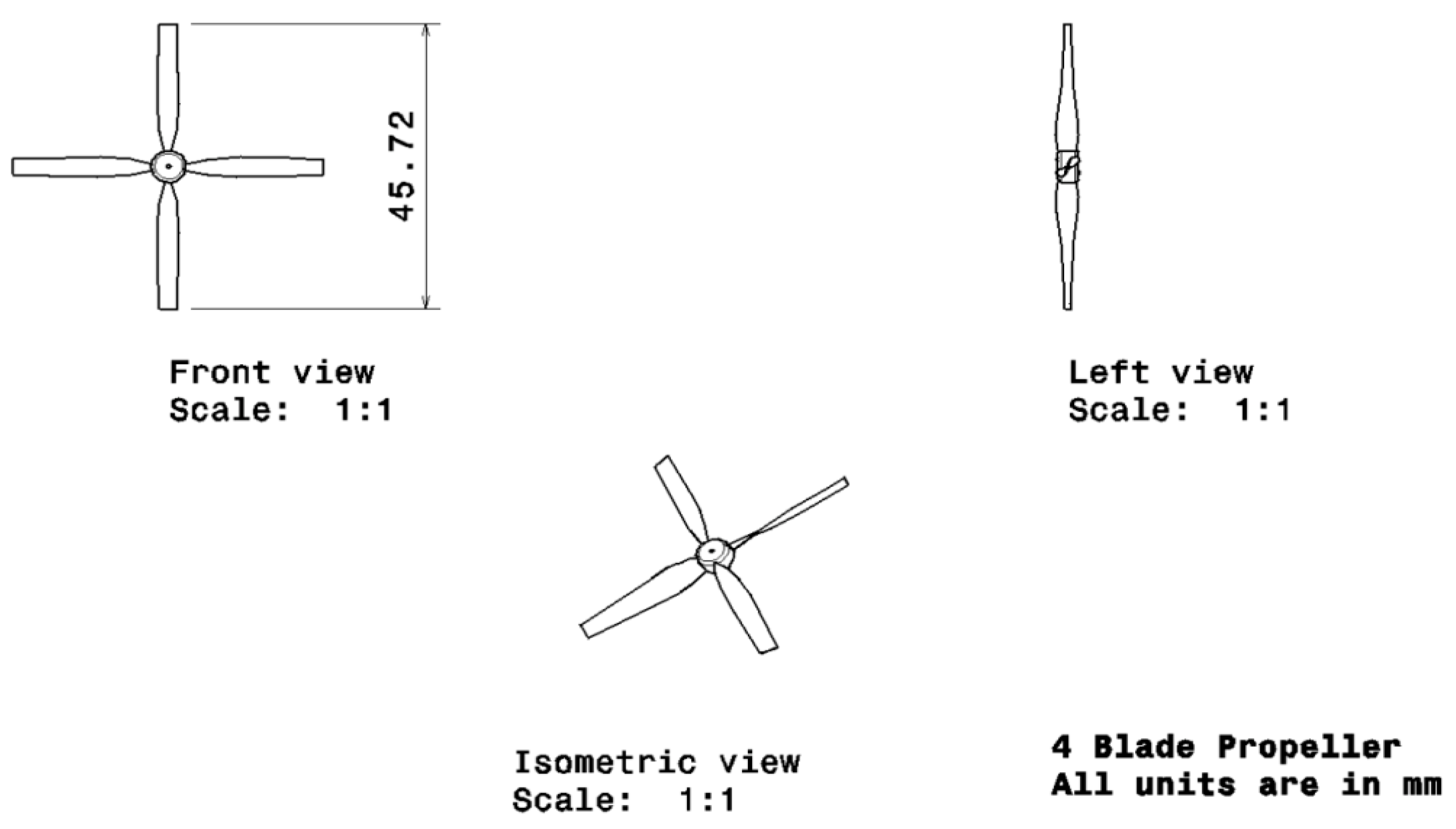
| [13] | - | Dia = 4.57 cm, Pitch = 4.65 cm, Pitch angle = 72.85°, Chord = 0.56 cm | - | - |
| [31] | Lead acid batteries | - | - | Thruster model 250,tritech ST 725 sonar, PC 104 pentuim processers |
| [33] | - | - | - | Microcomputers, gyroscopes |
| [34] | - | - | STM32F407 microcontroller and STM32F103ZET6, microcontroller | - |
| [38] | - | - | - | Torpedo shaped hull |
| [40] | - | - | PID type-SISO controls | - |
| Symbol | Meaning |
|---|---|
| Payload weight (kg) | |
| Overall weight of the UAV (kg) | |
| Wing loading (kg/cm2) | |
| Planform area of the wing (cm2) | |
| Wingspan (cm) | |
| Chord at root of the wing (cm) | |
| Efficiency | |
| L | Fuselage’s length (cm) |
| Length of the UAV (cm) | |
| Diameter of the fuselage (cm) | |
| Taper ratio | |
| Chord at tip of the wing (cm) | |
| Mean aerodynamic chord of the wing (cm) | |
| Position of mean aerodynamic chord in “y” direction(cm) | |
| Surface area of the horizontal tail (cm2) | |
| Volume coefficient of the horizontal tail | |
| Distance between MAC of horizontal tail to MAC of wing (cm) | |
| Horizontal tail-span (cm) | |
| Aspect ratio of the horizontal tail | |
| Velocity of the atmospheric fluid (m/s) | |
| Static thrust (oz) | |
| Dynamic thrust (N) | |
| Density of the working fluid (kg/m3) | |
| Radius of the propeller (cm) | |
| Coefficient of lift | |
| Disc area of the propeller (cm2) | |
| Velocity at forward manuvering (m/s) | |
| Design constant | |
| Mechanical power required (W) | |
| Drag (N) | |
| Pitch angle (˚) | |
| R | RPM of the propeller |
| p | Pitch of propeller (cm) |
| Swept angle at leading edges (le) (˚) |
| Material Name | Weight of the UAV (N) | Immerse Force on UAV (N) | Lift Force Needs to Be Generated by Wing (N) |
|---|---|---|---|
| FR-4 Woven GFRP | 0.0067 × 1840 × 9.81 = 120.94 | 0.0067 × 1025 × 9.81 = 67.37 | 120.94 − 66.00 = 54.94 |
| CFRP-UD-Prepreg | 97.36 | 30.38 | |
| KFRP-UD-49-Epoxy | 90.17 | 23.20 | |
| GFRP-S-UD-Epoxy | 130.68 | 63.71 | |
| GFRP-E-UD-Epoxy | 128.72 | 61.75 | |
| GFRP-E-Fabric-Epoxy | 124.14 | 57.17 | |
| Mg. Alloy | 117.61 | 50.64 | |
| Al. Alloy | 180.00 | 114.02 | |
| CFRP-UD-Wet | 99.19 | 32.22 | |
| CFRP-Woven-Wet | 94.81 | 27.84 | |
| CFRP-Woven-Prepreg | 92.78 | 25.81 | |
| GFRP-E-Wet-Epoxy | 120.88 | 53.91 |
| Sl. No. | Hydrofoil for Wing | Minimum CD | Maximum CL | Angle of Attack (˚) |
|---|---|---|---|---|
| 1 | NACA 0006 | 0.0047 | 0.81 | 8.00 |
| 2 | NACA 0008 | 0.0052 | 0.97 | 9.75 |
| 3 | NACA 0012 | 0.0062 | 1.24 | 14.75 |
| 3 | NACA 0015 | 0.0073 | 1.27 | 16.75 |
| 4 | NACA 0018 | 0.0084 | 1.26 | 16.50 |
| Sl. No | Location (cm) | Pitch Angle ( ) | Chord Length (cm) |
|---|---|---|---|
| 1 | 0.2286 | 72.85 | 0.2794 |
| 2 | 0.4572 | 58.31 | 0.4064 |
| 3 | 0.6858 | 47.20 | 0.4318 |
| 4 | 0.9144 | 39.00 | 0.4064 |
| 5 | 1.143 | 32.94 | 0.381 |
| 6 | 1.3716 | 28.37 | 0.3556 |
| 7 | 1.6002 | 24.83 | 0.3302 |
| 8 | 1.8288 | 22.05 | 0.3048 |
| 9 | 2.0574 | 19.80 | 0.2794 |
| 10 | 2.286 | 17.95 | 0.254 |
| Aerofoil | CD | Aerofoil | CD | Aerofoil | CD |
|---|---|---|---|---|---|
| NACA 0012 | 0.025 | NACA 6409 | 0.019 | NACA 2410 | 0.018 |
| NACA 2414 | 0.019 | NACA 0024 | 0.030 | NACA 2412 | 0.018 |
| NACA 2415 | 0.020 | NACA 2408 | 0.018 | NACA 22112 | 0.020 |
| NACA 25112 | 0.028 | NACA 23012 | 0.020 | NACA 63A010 | 0.030 |
| NACA 63012A | 0.026 | NACA 63-215 | 0.021 |
| S. No | Design Description | Design Data | S. No | Design Description | Design Data |
|---|---|---|---|---|---|
| 1 | Span | 96 cm | 10 | Taper Ratio (FS) | 0.95 |
| 2 | Wing area | 921.6 cm2 | 11 | Taper Ratio (BS) | 0.4 |
| 3 | Wing loading | 0.0062 kg/cm2 | 12 | Swept angle (FS) | 1.43° |
| 4 | Total weight | 5.7 kg | 13 | Swept angle (BS) | 11.31° |
| 5 | Span (forward swept) | 19.2 cm | 14 | M.A.C | 6.78 cm |
| 6 | Span(backward swept) | 28.8 cm | 15 | Aspect ratio | 14 |
| 7 | Chord root (FS) | 9.6 cm | 16 | Chord at 25% of span | 8.3 cm |
| 8 | Chord tip (FS) | 9.12 cm | 17 | Chord at 50% of span | 7.45 cm |
| 9 | Chord tip (BS) | 3.65 cm | 18 | Chord at 75% of span | 6.66 cm |
| Types of Meshes | Details of Statics of Mesh | |
|---|---|---|
| Number of Nodes | Number of Elements | |
| Case-1—Fine with curvature mesh | 226,904 | 832,042 |
| Case-2—Fine with area proximity mesh | 284,824 | 1401,871 |
| Case-3—Fine with both curvature and proximity mesh | 578,071 | 3214,567 |
| Case-4—Fine with Face Mesh set-up | 792,030 | 4251,425 |
| Case-5—Fine with Inflation Mesh set-up | 595,850 | 2145,789 |
| Drag on Fuselage Model through Experimental Outcomes [50,51,52] | Drag on Fuselage Model through This Imposed Computational Methods | Error Percentage |
|---|---|---|
| 9.75 N | 9.55654 N | 1.98 |
| Types of Meshes | Details of Statics of Mesh | |
|---|---|---|
| Number of Nodes | Number of Elements | |
| Case-1—fine adoptive mesh | 75,489 | 457,891 |
| Case-2—fine proximity | 352,541 | 298,571 |
| Case-3—fine curvature | 595,914 | 992,124 |
| Case-4—fine with controlled small sized elements formed on aerodynamic shapes | 898,124 | 1045,214 |
| Case-5—fine with controlled inflation is formed on aerodynamic shapes | 503,061 | 758,421 |
Publisher’s Note: MDPI stays neutral with regard to jurisdictional claims in published maps and institutional affiliations. |
© 2022 by the authors. Licensee MDPI, Basel, Switzerland. This article is an open access article distributed under the terms and conditions of the Creative Commons Attribution (CC BY) license (https://creativecommons.org/licenses/by/4.0/).
Share and Cite
Raja, V.; Madasamy, S.K.; Rajendran, P.; Ganesan, S.; Murugan, D.; A. Z. AL-bonsrulah, H.; Al-Bahrani, M. Nature-Inspired Design and Advanced Multi-Computational Investigations on the Mission Profile of a Highly Manoeuvrable Unmanned Amphibious Vehicle for Ravage Removals in Various Oceanic Environments. J. Mar. Sci. Eng. 2022, 10, 1568. https://doi.org/10.3390/jmse10111568
Raja V, Madasamy SK, Rajendran P, Ganesan S, Murugan D, A. Z. AL-bonsrulah H, Al-Bahrani M. Nature-Inspired Design and Advanced Multi-Computational Investigations on the Mission Profile of a Highly Manoeuvrable Unmanned Amphibious Vehicle for Ravage Removals in Various Oceanic Environments. Journal of Marine Science and Engineering. 2022; 10(11):1568. https://doi.org/10.3390/jmse10111568
Chicago/Turabian StyleRaja, Vijayanandh, Senthil Kumar Madasamy, Parvathy Rajendran, Sangeetha Ganesan, Dharshini Murugan, Hussein A. Z. AL-bonsrulah, and Mohammed Al-Bahrani. 2022. "Nature-Inspired Design and Advanced Multi-Computational Investigations on the Mission Profile of a Highly Manoeuvrable Unmanned Amphibious Vehicle for Ravage Removals in Various Oceanic Environments" Journal of Marine Science and Engineering 10, no. 11: 1568. https://doi.org/10.3390/jmse10111568