Article

Development of a Structural-Functional Approach for Heterogeneous Glider-Type Marine Robotic Complexes’ Group Interaction to Solve Environmental Monitoring and Patrolling Problems

1
Institute of Hydrodynamics and Control Processes, Saint-Petersburg State Marine Technical University, Lotsmanskaya St., 3, 190121 Saint-Petersburg, Russia
2
Research and Development Department, Saint-Petersburg State Marine Technical University, Lotsmanskaya St., 3, 190121 Saint-Petersburg, Russia
3
JSC Oceanos, Esenina St., 19, 194295 Saint-Petersburg, Russia
4
Department of Applied Mathematics and Mathematical Modelling, Saint-Petersburg State Marine Technical University, Lotsmanskaya St., 3, 190121 Saint-Petersburg, Russia
5
Emercom of Russia, Davydkovskaya St., 7, 121352 Moscow, Russia
*
Author to whom correspondence should be addressed.
J. Mar. Sci. Eng. 2022, 10(10), 1531; https://doi.org/10.3390/jmse10101531
Submission received: 27 July 2022 / Revised: 29 August 2022 / Accepted: 5 September 2022 / Published: 19 October 2022
(This article belongs to the Special Issue Advances in Marine Vehicles, Automation and Robotics)

Abstract

:
Glider-type autonomous underwater vehicles are today one of the most promising areas of marine robotics. This is confirmed by the frequent and remarkable results of various research missions and projects. The cumulative group application of underwater and no less innovative wave gliders can significantly reduce the time of obtaining oceanographic data. Together with wave gliders, one group of such robotic objects can significantly increase the efficiency, time and volume of obtaining oceanographic data. There is big interest in increasing the functionality of such a group. This article presents one of the possible alternatives to increase the functionality of a group of underwater and waveguide hang gliders. We present the process of upgrading the existing design, control algorithms and software of the SHADOW underwater glider, which was developed by the teams of the St. Petersburg State Marine Technical University (SMTU) and Okeanos JSC in order to jointly study the monitoring of underwater potentially dangerous objects with the St. Petersburg State Fire Service EMERCOM of Russia. A structural-functional approach to the group application of underwater and waveguides is also proposed, which is capable of providing oceanographic, meteorological and environmental monitoring data online, based on the developed multilayer system for planning the trajectories of group movement of objects. The results of full-scale sea trials and the developed algorithms are demonstrated.

1. Introduction

Areas of operational oceanography, coupled with environmental monitoring, have recently undergone hyper-intensive development. Therefore, it is necessary to use advanced technologies which, in a manner as definite and timely as possible, provide the requested quality level of monitoring and forecasting the state of seas and oceans, and thus achieve operational data collection with a high level of reliability and economic efficiency. Ocean observations come from a variety of sources, including satellites, in situ observation platforms such as fixed and drifting surface and underwater buoys, escort vessels, research vessels and autonomous unmanned underwater vehicles (AUVs) with an increased autonomy called gliders, which are the most used method today.
There are projects concerning the application of gliders of various types, including groups of gliders. Underwater gliders are used to explore and monitor large areas [1,2,3,4,5,6]. The payload installed on these vehicles makes it feasible to analyze the state of the marine environment and obtain operational information on weather conditions in the sailing area [2,7,8]. Moreover, underwater gliders are used in the Arctic zone [9,10], in extreme environments, which allows obtaining data on ice, oceanographic data on the presence of impurities as a result of melting glaciers, eddy formation processes [11,12], geological exploration [13,14], passive acoustic monitoring [15,16], including marine mammals movement surveillance [17,18,19,20], etc. Apart from that, it is possible to highlight an area of group application of underwater gliders. There are a number of successful studies in which groups of the SLOCUM-type underwater gliders were used [21,22,23,24]. The group significantly increases the speed and completeness concerning obtaining oceanographic data and makes it possible to form large databases, which are used for climate change prediction [25,26].
Development of the control system for a group of marine robotic complexes (MRCs) is an extremely complicated and time-consuming task, taking into account the specifications of the vehicles themselves (gliders) and the conditions for their application. At the moment, developers use numerous variations of centralized and decentralized control technologies, including virtual leaders, or control of the specified key points for each agent in the group separately. Implementation of such systems is quite simple and is successfully used to solve problems not only in the field of marine robotics. However, in order to promptly correct the group path planning in a dynamically changing environment, it is important to consider both the changing parameters of the external environment and the existing hardware limitations imposed on the group. Considering the oil and gas industry development and the statement of problems related to year-round monitoring and maintenance of underwater objects, fundamentally new goals are set for the development of both underwater vehicles and for the interaction of such vehicles in a group [27,28].
There are similar developments from different research groups. For instance, in these articles, the wave glider is considered as a repeater of the signal from the underwater glider and back, this helps to instantly control its operation [29,30]. In this article, we present a system for the autonomous identification and tracking of ocean fronts by coordinating the sampling efforts of a heterogeneous team of autonomous surface vehicles and autonomous underwater vehicles [31]. Interaction of robots with scientists off-site and work in a hierarchical structure for the autonomous collection of visual frames of interesting underwater areas at various scales and environments is described in the work [32].
As can be seen, in many articles published to the date, the wave gliders plays the role of a repeater that allows us to receive and transmit data from underwater vehicles (including underwater gliders). However, these works did not consider the problems of group interaction of devices. Moreover, approaches to the interaction of heterogeneous groups consisting of wave and underwater gliders have not been considered before.
The authors propose the development of fundamentally new constructive and functional approaches for the interaction of groups of underwater and wave gliders based on: (1) the presented algorithms of the planning and maintaining system; (2) taking into account the design features of the device. The proposed solutions make it possible to expand the range of MRC tasks to be solved, such as, for instance, patrolling and monitoring underwater potentially dangerous objects, searching for hydrocarbon deposits, etc. At the same time, the use of groups of gliders is increasing the duration of the work performed, which will significantly reduce economic costs.
Everything in the complex leads both to the need to work out the latest structural and functional approaches to the use of marine robotic systems (gliders) and their groups with a high level of functionality, mobility and autonomy, and to the necessity to verify the results of the study in full-scale experimental conditions and pilot operations.
Below, in Section 2, we provide general information about the objects, goals and objectives of the study, as well as existing developments and solutions in this area. A detailed description of the development of a group interaction system for a heterogeneous group of marine vehicles is described in Section 3.

2. The Problem Statement

The aim of the work is to develop a theory of using groups of underwater and wave gliders in relation to the applied problems of monitoring and patrolling, including patrolling areas with underwater potential hazardous objects (UPHOs) [28,33,34]. The combination of two heterogeneous vehicles makes it possible to receive and transmit data from the underwater glider in near real time modes, as well as to quickly correct the position of the underwater glider(s) and change the mission parameters.
Our research is based on the consideration of the following glider models: the SHADOW underwater glider and a wave glider developed by SMTU and Oceanos JSC, as well as the possibility of their complex application [35,36,37]. Underwater and wave glider models are shown in the Figure 1.
To achieve the primary objective of the study, namely the interaction of actual vehicles in a group, it is necessary to solve the following problems (subject to the availability of operating low-power broadcast stations, communication equipment and MRC navigation equipment with a certain technical specification):
  • Ensuring a sufficient distance between objects, which allows maintaining an operational communication channel;
  • Setting up the intra-group logic for vehicles’ action planning in case of unforeseen situations;
  • Maintaining the group while the group is moving.
A key factor for the successful completion of the mission is the availability of high-quality communication between the vehicles (both hydroacoustic and radio/satellite communication). As an example of hydroacoustic communication channel implementation, we consider the parameters of a widely used acoustic modem from Evologic (30/60 underwater acoustic modem) and USBL transceivers. The operating range of such a system is approximately 1 km. Generally, the acoustic modem is installed in the underwater part of the wave glider. In this case, an important and necessary condition for fulfilling the mission is not only a high degree of complexity of the control system (both a separate device and a group of devices), but also the design features of the vehicles associated with certain glider design schemes. A case, when a group of gliders is assigned the task to monitor environment state changes in the area of a given position (similar tasks are the UPHO monitoring tasks) is considered.
Let there be N number of robots in some space of global coordinates M with the coordinates (1):
P g r o u p ( i ) = [ x ( i ) g r o u p , y ( i ) g r o u p ]
The set of points P g r o u p ( i ) composes an H formation; its center is defined as the center of mass of the figure defined by the points x ( i ) g r o u p , y ( i ) g r o u p . The task for the group is to move to the given target points T p = [ T p 1 , T p 2 , T p 3 , T p 4 ] , retaining the H formation. We consider the formation as the spatial structure of the vehicles in a group. In order to coordinate an interaction, the elements of the group should have an information communication channel, but its range has a physical limitation. In this case, it is necessary to create such a type of formation that prevents the vehicles from moving away from each other by more than the radius R, which is the maximum allowable range of the optimal communication system channel. The formalized statement of the problem is shown in the Figure 2:
In Figure 2, U G 1 , U G 2 , W G are positions of two underwater and one wave glider, respectively, describing the function of the formation structure H g r o u p ( U G 1 , U G 2 , W G ) . D 1 , D 2 , D 3 are distances between U G 1 , U G 2 , W G accordingly. Φ is an area in which it is required to maintain the formation of the group. This area is based on the intersection of three circles Φ = R U G 1 R U G 2 R W G . Precisely in area Φ , a group of gliders should try to maintain the preassigned formation H g r o u p , performing reconfiguration and maneuvering. Thus, it is mandatory to satisfy the following condition (2):
H g r o u p ( U G 1 , U G 2 , W G ) Φ
In the case of a real application of the group, it is important to take into account the presence of stratification of the marine environment and external disturbing influences F d , (for example, currents) that can introduce significant deviations into the trajectory of the underwater glider.
Under this assumption, we take the conditions for the group functioning within the Baltic Sea, where the stratification of the marine environment in relation to gliders can be neglected [38], and the average speed of steady currents in the straits ranges from 0.5 to 2 knots. As a result, with a minimum direct lateral impact at 0.5 knots on a vehicle moving at a longitudinal velocity at 0.8 knots, its lateral deviation from the target trajectory in the direction of the resulting velocity vector will be ~1.3 km per 1 h of movement. Considering the submerged state of the underwater glider and the operating range of acoustic communication of 1.5–1.7 km (inclined range), such a flow practically takes the vehicle out of the Φ group area. In order to keep vehicles within the Φ area, it is important to ensure sufficient glider maneuverability, namely, the minimum allowable glider turning radius R , which satisfies the condition (2).
A closer look at motion models of the underwater glider in a group is presented in the Section 3.

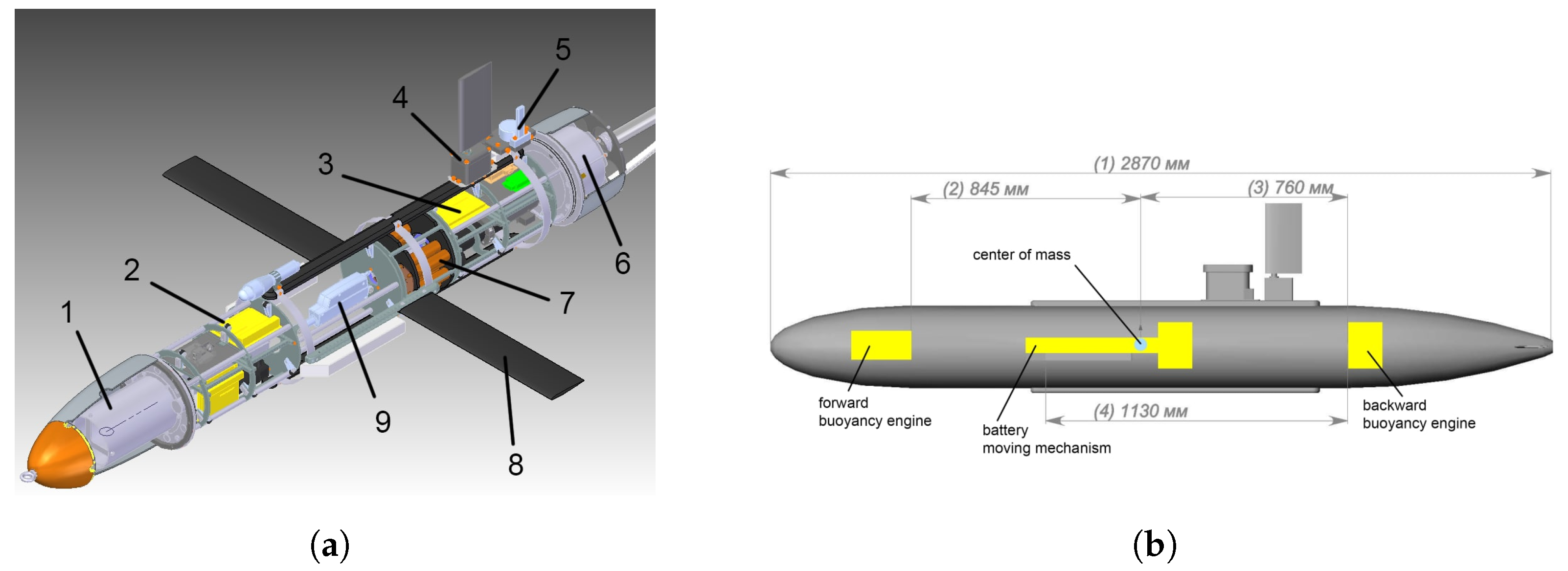
SHADOW Underwater Glider Model

A steady motion model of an underwater glider with independence assumption of the glider immersion depth function in general form is presented in the expression (3) [39,40,41].
Y ˙ = ( θ , x ) = Σ p ( θ , x ) Σ θ ( θ , x ) r p ˙ = ( 1 / m p ) P p V W r p P p ˙ = ( u ¯ ) m b ˙ = u b
where x—m-vector of internal coordinates; Y ˙ —n-vector of position and orientation vector of the associated reference frame relative to the base one, n 6 ; ( θ , x ) —n-vector of kinematic relations; Σ p ( θ , x ) —vector of linear velocities of the associated reference frame relative to the base one; Σ θ ( θ , x ) —vector of angular velocities of the associated reference frame relative to the base one; M—mxm-matrix of mass-inertial parameters: its elements are mass, moments of inertia, and added masses of the glider; F ( x , Y , r p , P p , u , l , R ) —m-vector of external and internal forces and moments; herein l—design parameter vector, R—vector of hydrodynamic forces and moments; ( u ¯ ) = P p * W + F p + u , where u—(m–1) vector of control actions (internal forces affecting the movable load); W—glider angular velocity vector; r p —movable load position vector; P p —momentum vector of the movable load; m p —changing glider mass (ballast load); F p —gravity vector acting on a movable load in associated reference frame.
The direction of orientation angles and velocity vectors of the underwater glider is shown in the Figure 3 [42], where X Y Z is the glider-related reference frame; it should be noted that point O is the vehicle’s center of mass coordinate, which coincides with the reference frame center origin and is located at a distance of 1.4 m from the bow of the glider; γ —pitch angle of the glider; φ —heading angle of the glider; θ —roll angle of the glider; w x , w y , w z —angular velocities of the glider corresponding to the axes. It is necessary to note that the depth sensor is located in the bow of the glider. The glider rotation matrix is presented in the expression (4), where C ( θ ) and S ( θ ) are c o s ( θ ) and s i n ( θ ) accordingly.
R m = C ( θ ) C ( γ ) S ( φ ) S ( θ ) C ( γ ) C ( φ ) S ( γ ) C ( φ ) S ( θ ) C ( γ ) + S ( φ ) S ( γ ) C ( φ ) S ( γ ) S ( φ ) S ( θ ) S ( γ ) + C ( φ ) C ( γ ) C ( φ ) S ( θ ) S ( γ ) S ( φ ) C ( γ ) S ( θ ) S ( φ ) C ( θ ) C ( φ ) C ( θ )
Previously, the authors considered various methods of control of an underwater glider. In the articles [43,44], the authors made several assumptions that are important when designing a real vehicle. In particular, the variable z p is used by the authors as a variable point of application of the glider’s buoyancy. Implementation of this approach is extremely problematic in terms of designing a real vehicle, since it is necessary to develop such a system, which could simultaneously combine the vehicle’s buoyancy engine system (e.g., pumping oil from the internal reservoir) and the system for displacing the collected liquid in the transverse plane, taking into account the change in external volume. It is obvious that the implementation of such a system (with theoretical feasibility) is not only structurally complicated, but also extremely costly; moreover, it reduces the reliability and energy efficiency of the glider in operation.
Therefore, an actual prototype of the underwater glider has the piston/plunge mechanisms to implement the variable buoyancy engine system of the glider and internal engines which provide a change in pitch when moving the battery unit. The layout of the SHADOW underwater glider main modules is shown in the Figure 4, where (1) is forward buoyancy engine; (2)—navigation unit; (3)—onboard computer unit; (4)—steering gear; (5)—external antenna; (6)—backward buoyancy engine; (7)—roll control system; (8)—wing surfaces; (9)—trim control system. In the Figure 4b: (1)—length of the glider; (2)—position of the forward buoyancy engine relative to the glider’s center of mass; (3)—position of the backward buoyancy engine relative to the glider’s center of mass; (4)—length, which makes it possible to have an offset of the wings along the glider’s hull (initially, the wings are located at the glider’s center of mass point).
It is worth noting the implementation of two engine systems for changing the buoyancy (forward and and backward buoyancy engine systems), which allows the glider to enter the communication mode and adjust according to GNSS while the vehicle is on the water surface.
The primary parameters of the SHADOW underwater glider are shown in the Table 1.
The mass-inertial characteristics of the SHADOW underwater glider can be represented by the expression (5):
M i = M t C t C T T I t
where M t = ( m r + m k ) I o + M a , I o = o n e s ( 3 , 3 ) ; M a —added mass terms; C t = C A m r r r ; I t = I s + I r b + I a m r r r 2 m k r k 2 ; I a —added inertia terms; C A —added coupling terms, in the presented case
M a = [ 2.1 , 61.45 , 86.95 ] ,
I a = [ 0.64 , 10.78 , 11.12 ] ,
C a = [ 0.0 , 3.11 , 4.37 ] .
The change in the positions of the roll and trim control systems can be described with the following expressions:
r x = r r x r k = k x + R r ( c o s ( σ + p i / 2 ) + s i n ( σ + p i / 2 )
where r r x is trim control system offset along the OX axis; k x —position of the roll control system along the O X axis; R r —eccentricity of the roll control system along the O X axis; σ —roll control system rotation angle. As the main programming call for the implementation of the glider autonomous control system, C++ was chosen, which allows you to support both high- and low-level operations, including C++, which is a compiled programming language and which increases the speed of programs performed onboard the device. Including C++ consumes less RAM when executing programs. The program for mission planning and monitoring the condition of the underwater glider is also implemented in C++, taking into account the use of additional user libraries. The structure of the program is based on the modular principle of construction. A Raspberry Pi 3 single-board computer running under Ubuntu OS is installed as the main onboard computer on the slider. The battery pack is presented in the form of three parallel-connected sets of lithium-ion batteries with a total capacity of 50 A/h.
We investigate the motion mode of the glider during the turning maneuver. To do so, we set the following parameters: deviation angle of the rotary unit σ = 60 degrees; maximum forward buoyancy engine offset is r r x = 0.095 m. The simulation results are shown in the Figure 5.
The study of the developed model has shown that the turning radius of the glider with the configuration of the forward buoyancy engine is R ´ = 41 m.
The next step of the development was to change the arrangement configuration of the glider’s individual elements in order to study the maneuverability characteristics of the vehicle. In particular, the developers decided to implement a configuration with only backward buoyancy engine (shifting the glider’s center of mass backwards), as well as to move the wings backward by a distance of Δ = 712 mm. So, when the wings have a 712 mm offset backwards, the moment created by the wings will be 13.3 N*m. The resulting estimate for the hydrodynamic moment on the wings is twice as high as the estimate for the moment of the center of mass on the hull. Thus, offsetting the wings backwards should automatically lead to the appearance of a significant hydrodynamic moment on them, rotating the vehicle along the pitch. It follows from this that the pitch control system needs to shift the center of mass not by 95 mm, but only by 38 mm, or by 40 percent of the piston/plunge stroke.
Let us consider the results of the glider turning maneuver, taking into account the modified configuration of the buoyancy engine system and glider wings. The parameters used are similar to the first study. The results are shown in the Figure 6.
As seen above, the introduced design and hardware modification significantly increased the underwater glider’s maneuverability by reducing the turning radius R ´ = 21 m. An increase of more than 1.5 times allows a group of underwater gliders, when receiving the path correction data from the wave glider, to perform a quick turning maneuver to comply with condition (2). An example of a double turning circle mission is shown in the Figure 7.
At the same time, a reserve for increasing the maneuverability is retained due to the algorithms for the combined use of the glider’s roll control system and hydrodynamic rudder as a function of optimizing energy consumption with the adaptive kind of the mission.
The authors conducted several comparative tests to study the glider’s driving characteristics with different wing surfaces.
The launches of the device took place in the area of Lake Sapernoe in the Leningrad Region (Figure 8). This lake is characterized by clean, transparent water, which allows you to assess the movement of the glider visually. Moreover, there are practically no disturbing currents in it (the excitement is not more than 0.5 points), which makes it possible to best evaluate the results of the glider control system.
The first experiment was conducted to study the glider’s driving characteristics when the wings were located in the central part of the glider’s body. During the tests, values were obtained for the number of immersion/ascent cycles, energy expended and hydrodynamic characteristics, reflecting the dynamics of the apparatus in transient modes (roll and trim angles of the glider) (Figure 9).
The results of the experiment show that the device was able to successfully pass the specified trajectory. It is possible to note the high values of the angles of immersion and ascent of the device (about 38 degrees on immersion and 35 degrees on ascent). This feature can be explained by the fact that the device went to shallow water, and the control system simply did not have time to work out the target values, although the graph (Figure 9a) reflects the moments when the control system successfully brought the device to the specified planning angles (22 degrees). During the mission, the glider performed 38 dive/ascent cycles within 1 h.
The second experiment was conducted as part of the initiative work carried out by Oceanos JSC and St. Petersburg State Marine Technical University (SMTU) in 2020 in order to form a primary data array to ensure predictive modeling together with the St. Petersburg University of the State Fire Service of the EMERCOM of Russia, a series of full-scale trials of the upgraded SHADOW underwater glider [33,34,45,46,47]. In this experiment, the wings were shifted to aft.
In one of the given missions, the vehicle was tasked to pass borders of three given areas with a subsequent return to the starting point of the mission. RedWave long-base hydroacoustic navigation onboard system and buoys, located in the operating area of the sea trials, helped to obtain the vehicle’s position data. The results are presented in the Figure 10. Photos of the full-scale experiment are in the Figure 11.
As a result, it can be seen that the vehicle has passed the specified areas with a slight deviation from the target trajectory. The maximum diving depth was 10 m, the mission time was 1.5 h, the distance traveled during the experiment was 2 km.
As can be seen from the results of the full-scale experiment, the device completed a mission lasting 1 h and 50 min with a total distance of 1.5 km, completing 150 cycles of diving ascent with a maximum depth of 10–15 m. It can be seen that the device passed the specified target trajectory (highlighted in black in the figure), with minor deviations. Separately, you should pay attention to the moment of turning the glider on the third section, when the device exits the specified region. The developed configuration of the glider made it possible to make a U-turn within 20 m and reach the specified trajectory of movement.

3. Development of a Group Interaction System

An important element in expanding the functionality of MRC groups’ application is the development of adaptive systems for group interaction, which allow heterogeneous objects (heterogeneous groups) to organize their operation in unknown environments. It should be noted that the wave glider is the connecting link of the group and allows correcting and analyzing the current group state. Since this vehicle has a larger onboard energy reserve due to the solar cells available, its onboard computer system makes additional calculations concerning the intra-group state in real time. That makes it possible to quickly adjust the path-planning system for each vehicle or the group as a whole. In particular, it is not uncommon to change the mission “on the fly”. The reason for this may be the detection of obstacles, the inability to overcome a current in a sailing area or a significant deviation from the target parameters. In this case, it is important to develop such a group management system, including a group motion path-planning system, which would consider the characteristics of the group (homogeneous and heterogeneous groups) and allow the group to continue the mission despite the changed environmental parameters that have arisen. A detailed description of the mathematical model of the developed wave glider was presented by the authors in the articles [48,49,50,51].
As discussed above, underwater gliders may be of hybrid design. Examples of such vehicles are certain versions of gliders presented in the articles [52,53,54,55,56]. Some of the hybrid glider models are shown in the Figure 12.
Such modernization of the glider design is required in the following cases when the glider:
  • moves in horizontal plane;
  • overcomes the strong current zones (overcomes the thermocline);
  • needs functionality and maneuverability improvement in order to overcome obstacles as well.
A communication system between vehicles is a basis of any group control system. Examples of the interaction of vehicles in various approaches to the implementation of group control systems are described in detail in the papers [57,58,59].
Thus, in a centralized system (which has an external supervisor), vehicles do not interact with each other, but only transmit the required information to a single device that processes the data received from all vehicles. This approach provides lower computational costs on each of the devices, ease of implementation and scaling, but also faces a risk when data do not reach the supervisor or the supervisor is out of order. In this case, the group ceases to function.
In a decentralized approach, each vehicle communicates with another one. The approach is highly dependent on the communication channel between the vehicles; though it is quite difficult to implement the approach, it is more flexible and allows increasing the overall survivability of the group.
Each developer decides on their own which approach to implement, considering the goals and objectives of the project. At the same time, in order to implement the control system and the MRC group path planning, taking into account the peculiarities of the communication systems (both hydroacoustic and radio communications), it is advisable to use a centralized control system, in which the supervisory device is a wave glider capable of providing constant monitoring and an analysis of the group state. The multilevel system for the MRC group path planning [60], developed earlier by the authors, is based on the approaches of using the hybrid planners. Its structure is shown in the Figure 13.
This planning method was based on the method of potential fields, which provides local planning of the group’s path, and the RRT* method, which forms the global trajectory of the group’s motion. We successfully carried out full-scale trials confirming the efficiency of the developed algorithms [61].

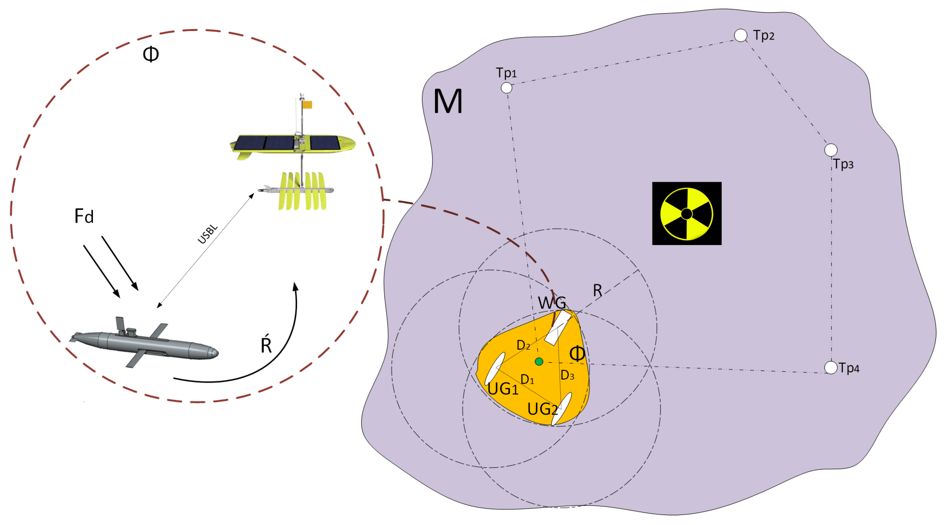
Development of an Algorithm for a Single Field of View of the MRC Group

It should be noted that it is of high importance that the group is able to perceive the overall environment for the best decision making in a dynamically changing environment. In view of this, we developed an algorithm that allows implementing a single field of view of the group, and, thus provides the best options for formation reconfiguration and motion in a non-deterministic environment.
The developed algorithm combines a system for data aggregation from the hydroacoustic and/or optical sensor system of each AUV and a system responsible for the change in each AUV state and its transition to the appropriate mode. Based on the data received from the sensor system, we analyze what percentage of its coverage area is occupied by an area with a visible obstacle. The sensory system model can be represented with the following Equation (7):
σ { ψ ξ / 2 , ψ + ξ / 2 } x s o n = x c + R r a n g e c o s ( σ ) y s o n = y c + R r a n g e s i n ( σ )
where ψ is orientation angle; ξ —a sonar and/or lidar viewing width; σ —sector received by sonar. Variables x s o n and y s o n describe the received coordinates of the sector, in which the data is captured by the sonar or lidar. The array of all calculated points β can be written as (8):
β = [ x s o n , y s o n ]
An obstacle detection occurs when the condition below is met (9)
P p = β o b s ,
where o b s is the positions of obstacles.
Since the ray can cross the obstacle twice, it is necessary to calculate the distances to the points of intersection and select the minimum point from the resulting array in relation to the AUV (10):
D β = | p s t a r t P p | P o b s = m i n ( P p ( D β ) )
Based on the data received from the sensor system, we can analyze what percentage of its coverage area is occupied by an area with a visible obstacle. To do so, let us compare a number of parameter P p values and the rays β (as the number of rays that are out of the obstacle area) and describe the obstacle avoidance area for each AUV. Examples of how the total field of view can be estimated are shown in the Figure 14.
The comparison made allows estimating the percentage of the sensory system being filled with the range of free Ω values. It is also possible to estimate the overall completeness of the Ω t o t a l sensory system by the total sum of all Ω i parameters from each AUV, shown in the Figure 15.
The presented algorithm makes it possible to complement the group management system of the AUV group based on the existing common field of view. The possibility of using this algorithm in devices operating in natural environments requires a laboratory experiment, since the efficiency of the algorithm directly depends on the external conditions of the marine environment, such as turbidity of water and other factors. The presented algorithm makes it possible to complement the group management system of the AUV group based on the existing common field of view.
Determination of the Ω t o t a l area completeness percentage will allow making up the criteria for the transition of the group to various formation reconfiguration scenarios. The research forms a basis for the authors to conduct the future researches.

4. Conclusions

In the paper under consideration, the results of a constructive change in the existing model of the SHADOW underwater glider were demonstrated. Such results are relevant for the MRC group application, as well as for the low-power broadcast station operation in constrained and shallow sailing areas. The study showed that placing the buoyancy engine system and wing surfaces backwards provides a greater maneuverability of the vehicle, including the turning radius of the glider R ´ = 21 m, which is almost two times less than the standard glider configuration. Moreover, placing the wings backwards led to a decrease in the pitch control system, which reduces the consumption of the glider’s energy system and increases its autonomous operation time. The conducted field experiments demonstrated the successful use of an underwater glider in order to monitor the specified areas of the water area. The described design changes, namely, the displacement of the wing surfaces into the aft part of the glider, led to a decrease in the radius of rotation of the device of more than 1.5 times and, as a consequence, an increase in its maneuverability. The achieved indicators of the turning radius make it possible to use the glider as part of the MRC group.
The described algorithm, which forms a single field of view of the group, allows further formation of the logic of the behavior of the AUV group during movement process in uncertain environments. The possibility of using this algorithm in devices operating in natural conditions requires a laboratory experiment, since the effectiveness of the algorithm directly depends on the external conditions of the marine environment, such as water turbidity and other factors.
In further research, the authors plan not only to study aspects of using neural network approaches in the group control system and the implementation of MRC route planning, but also to simulate the developed neural network systems and algorithms, as well as additionally conduct full-scale sea trials of existing MRC models.

Author Contributions

Conceptualization, V.R.; methodology, V.R.; validation, A.G.; formal analysis, T.S.; investigation, A.M. and A.G.; resources, D.N.; data curation, V.R. and D.N.; software A.M.; writing—original draft preparation, A.M. and V.R.; writing—review and editing, D.N.; visualization, A.G. and T.S.; supervision, I.K. and D.N.; project administration, I.K.; funding acquisition, D.N. All authors have read and agreed to the published version of the manuscript.

Funding

The research was partially funded by the Ministry of Science and Higher Education of the Russian Federation as part of the World-Class Research Center program: Advanced Digital Technologies (contract No. 075-15-2020-903 dated 16.11.2020).

Institutional Review Board Statement

Not applicable.

Informed Consent Statement

Not applicable.

Data Availability Statement

Not applicable.

Acknowledgments

The authors thank Ekaterina Nikitina for significant help in the article preparation.

Conflicts of Interest

The authors declare no conflict of interest.

References

  1. Wagawa, T.; Igeta, Y.; Honda, N.; Abe, S.; Ito, M.; Okunishi, T.; Hasegawa, D.; Kakehi, S.; Setou, T.; Shimizu, Y. Hydrographic observations in the Japan Sea with an underwater glider. In Proceedings of the 2016 Techno-Ocean (Techno-Ocean), Kobe, Japan, 6–8 October 2016; pp. 595–598. [Google Scholar] [CrossRef]
  2. Testor, P.; Meyers, G.; Pattiaratchi, C.; Bachmayer, R.; Hayes, D.; Pouliquen, S.; Villeon, L.; Carval, T.; Ganachaud, A.; Gourdeau, L.; et al. Gliders as a Component of Future Observing Systems. In Proceedings of the OceanObs’09: Sustained Ocean Observations and Information for Society, Venice, Italy, 21–25 September 2009; Hall, J., Harrison, D.E., Stammer, D., Eds.; ESA Publication: Venice, Italy, 2009; Volume 2. [Google Scholar] [CrossRef] [Green Version]
  3. Kozhemyakin, I.; Rozhdestvenskij, K.; Ryzhov, V. Underwater gliders: Yesterday, today, tomorrow (part 1). Mar. Bull. 2013, 1, 113–177. [Google Scholar]
  4. Kozhemyakin, I.; Rozhdestvenskij, K.; Ryzhov, V. Underwater gliders: Yesterday, today, tomorrow (part 2). Mar. Bull. 2013, 2, 98–101. [Google Scholar]
  5. Gajkovich, B.; Zanin, V. Issues of creating a family of marine gliders as elements of a global maritime security system. In Proceedings of the IX All-Russian Scientific and Practical Conference “Advanced Systems and Control Problems”, Krasnaya Polyana, Sochi, Russia, 7–11 April 2014; pp. 211–218. [Google Scholar]
  6. Gajkovich, B.; Zanin, V.; Kozhemyakin, I. Issues of development of marine robotic platforms on the example of the creation of the underwater vehicle “Glider”. In Proceedings of the XI All-Russian Scientific and Practical Conference “Advanced Systems and Control Problems”, Rostov on Don, Russia, 6–8 April 2016; pp. 151–163. [Google Scholar]
  7. Chang, D.; Zhang, F.; Edwards, C. Real-Time Guidance of Underwater Gliders Assisted by Predictive Ocean Models. J. Atmos. Ocean. Technol. 2015, 32, 562–578. [Google Scholar] [CrossRef]
  8. Testor, P.; Mortier, L.; Lheveder, B.; Taillandier, V.; Send, U.; Smeed, D.; Merckelbach, L.; Alvarez, A.; Tintore, J.; Casas, B.; et al. Regional in-situ observatory: Glider observations in the northwestern Mediterranean Sea in winter 2008 (EGO). In Proceedings of the GODAE Final Symposium, Nice, France, 12–15 November 2008. [Google Scholar]
  9. Lee, C.; Melling, H.; Eicken, H.; Schlosser, P.; Gascard, J.C.; Proshutinsky, A.; Fahrbach, E.; Mauritzen, C.; Morison, J.; Polykov, I. Autonomous Platforms in the Arctic Observing Network. In Proceedings of the OceanObs’09: Sustained Ocean Observations and Information for Society (Volume 2), Venice, Italy, 21–25 September 2009; Hall, J., Harrison, D.E., Stammer, D., Eds.; ESA Publication: Venice, Italy, 2009. WPP-306. [Google Scholar] [CrossRef] [Green Version]
  10. Perry, M.J.; Briggs, N.; Gray, A.; Lee, C.; Rehm, E.; D’Asaro, E.; Gudmundsson, K.; Kallin, E.; Lampitt, R.; Poulton, N.; et al. Optical observations of large diatoms and sinking particles during the North Atlantic Spring Bloom made from seagliders, floats and a ship. In Proceedings of the Ocean Optics XIX, Barga, Italy, 6–10 October 2008; pp. 38–40. [Google Scholar]
  11. McMillan, J. Autonomous Underwater Vehicle Operations in the Arctic. In Proceedings of the OTC Arctic Technology Conference, Copenhagen, Denmark, 23–25 March 2015. Paper Number: OTC-25543-MS. [Google Scholar] [CrossRef]
  12. Glenn, S.; Jones, C.; Twardowski, M.; Bowers, L.; Kerfoot, J.; Kohut, J.; Webb, D.; Schofield, O. Glider Observations of Sediment Resuspension in a Middle Atlantic Bight Fall Transition Storm. Limnol. Oceanogr. 2008, 53, 2180–2196. [Google Scholar] [CrossRef] [Green Version]
  13. Maevskij, A.; Gajkovich, B. Development of hybrid autonomous uninhabited vehicles for the exploration of hydrocarbon deposits. News Gas Sci. 2019, 2, 29–40. Available online: https://cyberleninka.ru/article/n/razrabotka-gibridnyh-avtonomnyh-neobitaemyh-apparatov-dlya-issledovaniya-mestorozhdeniy-uglevodorodov/viewer (accessed on 1 October 2022).
  14. The Use of Underwater Gliders for Geological Exploration. Robo Trends. 2018. Available online: http://robotrends.ru/pub/1837/primenenie-podvodnyh-glayderov-dlya-geologorazvedki (accessed on 9 July 2022).
  15. Dassatti, A.; Schaar, M.; Guerrini, P.; Zaugg, S.; Houegnigan, L.; Maguer, A.; André, M. On-board underwater glider real-time acoustic environment sensing. In Proceedings of the OCEANS 2011 IEEE, Santander, Spain, 6–9 June 2011; pp. 1–8. [Google Scholar] [CrossRef]
  16. Cauchy, P.; Heywood, K.; Queste, B.; Merchant, N.; Risch, D.; Testor, P. Passive Acoustic Monitoring from ocean gliders. In Proceedings of the 20-th EGU General Assembly, EGU2018, Vienna, Austria, 4–13 April 2018; p. 430. [Google Scholar]
  17. Küsel, E.; Munoz, T.; Siderius, M.; Mellinger, D.; Heimlich, S. Marine mammal tracks from two-hydrophone acoustic recordings made with a glider. Ocean. Sci. Discuss. 2016, 13, 273–288. [Google Scholar] [CrossRef] [Green Version]
  18. Olmstead, T.J.; Roch, M.A.; Hursky, P.; Porter, M.B.; Klinck, H.; Mellinger, D.K.; Helble, T.; Wiggins, S.S.; D’Spain, G.L.; Hildebrand, J.A. Autonomous underwater glider based embedded real-time marine mammal detection and classification. J. Acoust. Soc. Am. 2010, 127, 1971. [Google Scholar] [CrossRef]
  19. Aniceto, A.S.; Pedersen, G.; Primicerio, R.; Biuw, M.; Lindstrøm, U.; Camus, L. Arctic Marine Data Collection Using Oceanic Gliders: Providing Ecological Context to Cetacean Vocalizations. Front. Mar. Sci. 2020, 7, 585754. [Google Scholar] [CrossRef]
  20. Davis, R.; Baumgartner, M.; Comeau, A.; Cunningham, D.; Davies, K.; Furlong, A.; Johnson, H.; L’Orsa, S.; Ross, T.; Taggart, C.; et al. Tracking whales on the Scotian Shelf using passive acoustic monitoring on ocean gliders. In Proceedings of the OCEANS 2016, Monterey, CA, USA, 19–23 September 2016; pp. 1–4. [Google Scholar] [CrossRef]
  21. Schultz, B.; Hobson, B.; Kemp, M.; Meyer, J.; Moody, R.; Pinnix, H.; Clair, M. Multi-UUV missions using RANGER MicroUUVs. In Proceedings of the 13th Unmanned Untethered Submersible Technology, Durham, NH, USA, 24–27 August 2003; Available online: https://www.researchgate.net/publication/246892324_Multi-UUV_missions_using_RANGER_MicroUUVs (accessed on 1 October 2022).
  22. Healey, A.J.; Kim, J. Multiple Autonomous Vehicle Solutions to Minefield Reconnaissance and Mapping. In Proceedings of the Australian-American Conference on MCM, Washington, DC, USA, 3 November 1999; Available online: https://citeseerx.ist.psu.edu/viewdoc/download;jsessionid=5AD04CB5F41E47E435D5C85075F8A521?doi=10.1.1.606.2824&rep=rep1&type=pdf (accessed on 1 October 2022).
  23. Fiorelli, E.; Leonard, N.; Bhatta, P.; Paley, D.; Bachmayer, R.; Fratantoni, D. Multi-AUV Control and Adaptive Sampling in Monterey Bay. Ocean. Eng. IEEE J. 2006, 31, 935–948. [Google Scholar] [CrossRef] [Green Version]
  24. Naomi, L.; Derek, P.; Russ, D.; David, F.; Francois, L.; Fumin, Z. Coordinated Control of an Underwater Glider Fleet in an Adaptive Ocean Sampling Field Experiment in Monterey Bay. J. Field Robot. 2010, 27, 718–740. [Google Scholar] [CrossRef]
  25. Naomi, L.; Derek, P.; Francois, L.; Sepulchre, R.; David, F.; Russ, D. Collective Motion, Sensor Networks, and Ocean Sampling. Proc. IEEE 2007, 95, 48–74. [Google Scholar] [CrossRef] [Green Version]
  26. Nicholson, D.; Emerson, S.; Eriksen, C. Net community production in the deep euphotic zone of the subtropical North Pacific gyre from glider surveys. Limnol. Oceanogr. 2008, 53, 2226–2236. [Google Scholar] [CrossRef]
  27. Resident Robotics. 2018. Available online: https://oceanos.ru/resident_general (accessed on 1 October 2022).
  28. Yaomei, W.; Neil, B.; Worakanok, T.; Craig, B.; Sarik, S. Adaptive control for follower gliders mapping underwater oil patches. J. Hazard. Mater. 2022, 436, 129039. [Google Scholar] [CrossRef]
  29. Wave Glider Provides Gateway to Remote Exploration. 2018. Available online: https://www.whoi.edu/news-insights/content/wave-glider-provides-gateway-to-remote-exploration/ (accessed on 2 November 2021).
  30. Wave Glider Hot Spot. 2018. Available online: https://www.mbari.org/technology/emerging-current-tools/communications/wave-glider-based-communications-hotspot/ (accessed on 2 November 2021).
  31. McCammon, S.; Marcon dos Santos, G.; Frantz, M.; Welch, T.P.; Best, G.; Shearman, R.K.; Nash, J.D.; Barth, J.A.; Adams, J.A.; Hollinger, G.A. Ocean front detection and tracking using a team of heterogeneous marine vehicles. J. Field Robot. 2021, 38, 854–881. [Google Scholar] [CrossRef]
  32. Shkurti, F.; Xu, A.; Meghjani, M.; Gamboa Higuera, J.C.; Girdhar, Y.; Giguère, P.; Dey, B.B.; Li, J.; Kalmbach, A.; Prahacs, C.; et al. Multi-domain monitoring of marine environments using a heterogeneous robot team. In Proceedings of the 2012 IEEE/RSJ International Conference on Intelligent Robots and Systems, Vilamoura-Algarve, Portugal, 7–12 October 2012; pp. 1747–1753. [Google Scholar] [CrossRef] [Green Version]
  33. Maevskij, A.M.; Pechajko, I.A.; Tursenev, S.A. Application of marine robotic systems for monitoring and analysis of potentially dangerous underwater objects. Probl. Technosphere Risk Manag. 2021, 2, 32–39. [Google Scholar]
  34. Maevskij, A.M.; Zanin, V.Y.U.; Tursenev, S.A. Group application of underwater gliders in the task of monitoring underwater potentially dangerous objects on the example of emergency oil spill response. Probl. Technosphere Risk Manag. 2021, 3, 25–35. [Google Scholar]
  35. Zanin, V.Y.U.; Kozhemyakin, I.V.; Maevskij, A.M. The use of marine robotics in the tasks of operational oceanography. Domestic and foreign experience. Mar. Inf. Control. Syst. 2020, 1, 39–49. [Google Scholar]
  36. Voloshin, S.B.; Zanin, V.Y.U.; Maevskij, A.M. Aspects of the Application of Heterogeneous Groups of Robotic Complexes with Increased Autonomy, Including from Observatories, in Order to Obtain Oceanographic Data and Their Further Use for the Development of the Arctic Zone. Collection of Works of the Laureates of the International Competition of Scientific, Scientific, Technical and Innovative Developments Aimed at the Development and Development of the Arctic and the Continental Shelf. 2020; pp. 62–77. Available online: https://oceanos.ru/s1/files/File/2020_arktika_sb.pdf (accessed on 1 October 2022).
  37. Maevskij, A.M.; Kopylov, S.A. Aspects of using the grouping of underwater gliders for environmental monitoring of the world ocean. In Materials of the All-Russian Conference and School of Young Scientists “Technosphere Security Systems”; Southern Federal University: Taganrog, Russia, 2014; pp. 11–12. [Google Scholar]
  38. Dubravin, V.F. Evolution of Hydrochemical Structures of the Baltic Sea Waters; IO RAN.: Saint Petersburg, Russia, 2021; p. 354. [Google Scholar]
  39. Gurenko, B.; Maevskiy, A.; Kulchenko, A.; Beresnev, M. The Structure of Automatic Control Systems for Underwater Gliders. In Proceedings of the 4th International Conference on Control, Mechatronics and Automation, Barcelona, Spain, 7–11 December 2016; pp. 88–91. [Google Scholar] [CrossRef]
  40. Gurenko, B.V.; Maevskij, A.M.; Surov, K.A. Development and research of a positional trajectory controller for controlling the movement of an underwater glider Materials of the All-Russian conference and school of young scientists. Eng. Bull. Don 2019, 6, 20. Available online: http://www.ivdon.ru/ru/magazine/by_years (accessed on 1 October 2022).
  41. da Silva Tchilian, R.; Rafikova, E.; Gafurov, S.A.; Rafikov, M. Optimal Control of an Underwater Glider Vehicle. Procedia Eng. 2017, 176, 732–740. [Google Scholar] [CrossRef]
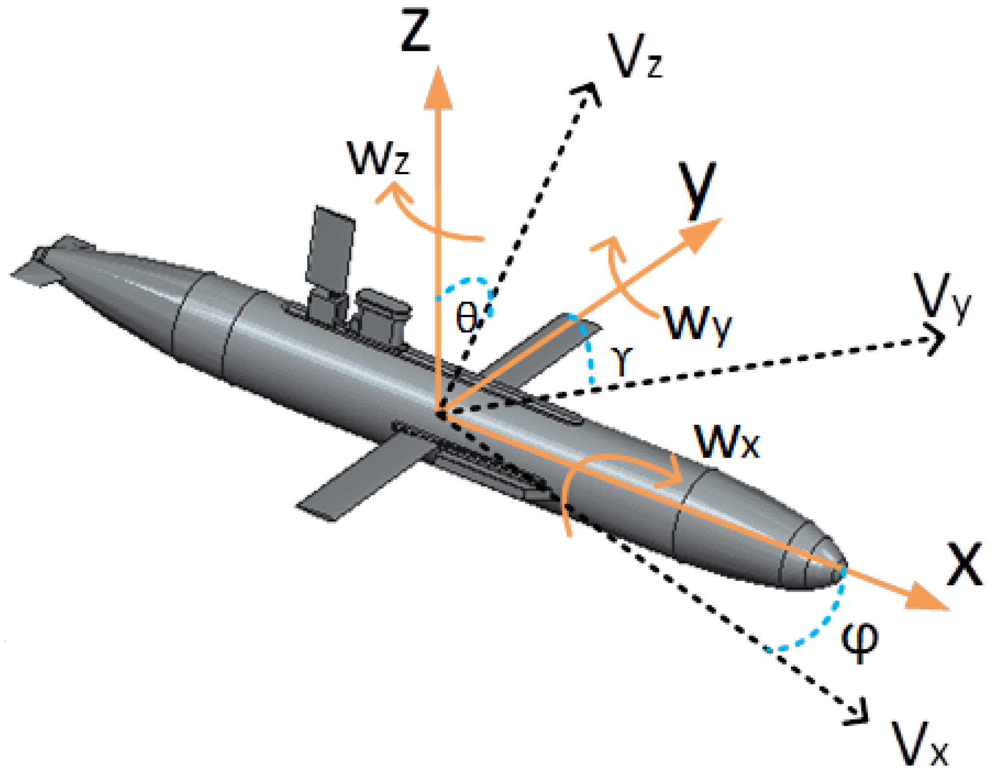
  42. Nikushchenko, D.V. On the selection of reference frames in investigation of an underwater vehicle dynamics. Mar. Intellect. Technol. 2015, 2-1, 19–25. [Google Scholar]
  43. Pshikhopov, V.; Gurenko, B.; Beresnev, M.; Nazarkin, A. Implementation of underwater glider and identification of its parameters. University Technologi Malaisia. J. Teknol. 2016, 78, 109–114. [Google Scholar] [CrossRef] [Green Version]
  44. Gurenko, B.; Surov, K.; Nazarkin, A. Research and development of a trajectory-position controller for an underwater glider. IOP Conf. Ser. Mater. Sci. Eng. 2020, 895, 012011. [Google Scholar] [CrossRef]
  45. Smirnov, A.S.; Tursenev, S.A.; Maevskiy, A.M. Robotics in Depth Monitoring. Civ. Prot. 2022, 3, 42–44. Available online: https://pressa.ru/ru/magazines/grazhdanskaya-zaschita/03-2022#/ (accessed on 1 October 2022).
  46. Maevskiy, A.M.; Smirnov, A.S.; Tursenev, S.A. Using of Groups of Marine Robotic Complexes as Systems for Detection and Monitoring of Underwater Potentially Dangerous Objects and Pollution in the Sea Area. Civ. Prot. 2022, 9, 34–36. Available online: https://pressa.ru/ru/magazines/grazhdanskaya-zaschita/09-2022#/ (accessed on 1 October 2022).
  47. Maevskij, A.M.; Zanin, V.Y.U.; Kozhemyakin, I.V. Promising high-tech export-oriented and demanded by the domestic market areas of marine robotics. Robot. Tech. Cybern. 2022, 10, 5–13. [Google Scholar]
  48. Ryzhov, V.A.; Potekhin, Y.P.; Rozhdestvenskij, K.V.; Kozhemyakin, I.V. Wave glider as an element of the marine global information and measurement system. In Proceedings of the X Scientific and Practical Conference “Perspective Systems and Management Tasks”, Dombai, Karachay-Cherkess Republic, Russia, 6–10 April 2016; Southern Federal University Press: Rostov-on-Don, Russia, 2016; pp. 101–112. [Google Scholar]
  49. Nikushchenko, D.; Ryzhov, V.; Tryaskin, N. Modeling hydrodynamic characteristics of wave glider. In Proceedings of the XII All-Russian Congress on Fundamental Problems of Theoretical and Applied Mechanics, Ufa, Russia, 19–24 August 2019; pp. 71–73. Available online: http://ruscongrmech2019.bashedu.ru/ (accessed on 1 October 2022).
  50. Ovchinnikov, K.; Ryzhov, V.; Sinishin, A.; Kozhemyakin, I. Experimental study of running characteristics of wave glider. In Proceedings of the XV All-Russian Scientific and Practical Conference “Advanced Systems and Control Problems”, Dombai, Karachay-Cherkess Republic, Russia, 6–10 April 2020; Southern Federal University Press: Rostov-on-Don, Russia, 2020; pp. 91–97. [Google Scholar]
  51. Wang, P.; Xinliang, T.; Wenyue, L.; Zhihuan, H.; Yong, L. Dynamic modeling and simulations of the wave glider. Appl. Math. Model. 2019, 66, 77–96. [Google Scholar] [CrossRef]
  52. Claus, B. Development of an Underwater Glider Equipped with an Auxiliary Propulsion Module. Ph.D. Thesis, Faculty of Engineering and Applied Science, Memorial University of Newfoundland, St. John’s, NL, Canada, 2010. Available online: https://research.library.mun.ca/8807/ (accessed on 1 October 2022).
  53. Dae-Hyeong, J.; Hyeung-Sik, C.; Jin-Il, K.; Hyunjoon, C.; Moon-Gap, J.; Jae-Heon, L. Design and control of hybrid underwater glider. Adv. Mech. Eng. 2019, 11, 1–9. [Google Scholar] [CrossRef] [Green Version]
  54. Tian, X.; Zhang, L.; Zhang, H. Research on Sailing Efficiency of Hybrid-Driven Underwater Glider at Zero Angle of Attack. J. Mar. Sci. Eng. 2022, 10, 21. [Google Scholar] [CrossRef]
  55. Niu, W.D.; Wang, S.X.; Wang, Y.H. Stability analysis of hybrid-driven underwater glider. China Ocean Eng 2017, 31, 528–538. [Google Scholar] [CrossRef]
  56. Sang-Ki, J.; Hyeung-Sik, C.; Jin-Il, K.; Ji-Youn, O.; Seo-Kang, K.; Thieu, N. Design and control of navigation system for hybrid underwater glider. IOS Press. J. Intell. Fuzzy Syst. 2019, 36, 1–16. [Google Scholar] [CrossRef]
  57. Pshikhopov, V.; Medvedev, M.; Gurenko, B. Algorithms of terminal control of multi-copters. Mekhatronika Avtom. Upr. 2019, 20, 44–51. [Google Scholar] [CrossRef]
  58. Pshikhopov, V.; Medvedev, M.; Gaiduk, A.; Kolesnikov, A. Control Method for Heterogeneous Vehicle Groups Control in Obstructed 2-D Environments. Lect. Notes Comput. Sci. 2016, 9812, 40–47. [Google Scholar] [CrossRef]
  59. Pshikhopov, V.; Medvedev, M. Group control of autonomous robots motion in uncertain environment via unstable modes. SPIIRAS Proc. 2018, 5, 39–63. [Google Scholar] [CrossRef]
  60. Maevsky, A.M.; Morozov, R.O.; Ryzhov, V.A.; Gorely, A.E. Development of a hybrid method for planning the movement of a group of marine robotic complexes in an a priori unknown environment with obstacles. Proc. South. Fed. Univ. Tech. Sci. 2021, 1, 30–47. [Google Scholar] [CrossRef]
  61. Maevskiy, A.; Gorelyi, A.; Morozov, R. Development of a Hybrid Method for Planning the Movement of a Group of Marine Robotic Complexes in a Priori Unknown Environment with Obstacles. In Proceedings of the 2021 IEEE 22nd International Conference of Young Professionals in Electron Devices and Materials (EDM), Souzga, Russia, 30 June–4 July 2021; pp. 461–466. [Google Scholar] [CrossRef]
Figure 1. SHADOW Underwater Glider and Wave Glider from SMTU and Oceanos JSC. (a) Underwater Glider SHADOW; (b) Wave glider by SMTU.
Jmse 10 01531 g001
Figure 2. Statement of the problem of gliders’ group motion.
Jmse 10 01531 g002
Figure 3. Direction of orientation angles and velocity vectors of the underwater glider.
Jmse 10 01531 g003
Figure 4. Layout of the SHADOW underwater glider main modules. (a) Basic modules; (b) Basic dimensions.
Jmse 10 01531 g004
Figure 5. Glider turning radius and values of linear and angular velocities (a), as well as pitch and roll angles during the turning maneuver (b).
Jmse 10 01531 g005
Figure 6. Glider’s turning radius, linear and angular velocity values (a), as well as pitch and roll angles when performing a turning maneuver (b) with wings and backward buoyancy engine.
Jmse 10 01531 g006
Figure 7. An example of (a) a turning radius R ´ = 25 m. (b) Glider’s double turning circle maneuver.
Jmse 10 01531 g007
Figure 8. Location of the experiment.
Jmse 10 01531 g008
Figure 9. The underwater glider motion trajectory during the first experiment. (a) Angle data; (b,c) IMU data; (d) Depth data.
Jmse 10 01531 g009
Figure 10. Underwater glider motion trajectory during the second experiment to reach the borders of 3 given areas. (a) Three mission regions; (b) 3D mission trajectory graph; (c) Angle data; (d) Depth data.
Jmse 10 01531 g010
Figure 11. Photos of the full-scale experiment. (a) The first experiment; (b) The second experiment.
Jmse 10 01531 g011
Figure 12. Hybrid underwater glider models: (a) SLOCUM hybrid; (b) China HUG; (c,d) SHADOW hybrid version by SMTU and Oceanos JSC.
Jmse 10 01531 g012
Figure 13. Developed hybrid path-planning system for the MRC group.
Jmse 10 01531 g013
Figure 14. Draft of the general field of view and decision-making on reconfiguration by the AUV group.
Jmse 10 01531 g014
Figure 15. Draft of the general field of view and decision-making on reconfiguration by the AUV group.
Jmse 10 01531 g015
Table 1. Primary parameters of the SHADOW underwater glider.
Parameter NameParameter Value
Mass of the glider138.45 kg
Forward buoyancy engine displacement1.3 L
Backward buoyancy engine displacement1.2 L
Mass of the trim control system10.2 kg
Offset of the trim control system along OX axis0.095 m
Mass of the rotation system (roll control system)8.3 kg
Roll control system rotation range along OX axis75 deg
Publisher’s Note: MDPI stays neutral with regard to jurisdictional claims in published maps and institutional affiliations.

