Review

A Review of Point Absorber Wave Energy Converters

1
School of Marine Science and Technology, Northwestern Polytechnical University, Xi’an 710072, China
2
Ocean Institute, Northwestern Polytechnical University, Taicang 215400, China
3
Key Laboratory of Ocean Acoustics and Sensing of the Ministry of Industry and Information Technology, Northwestern Polytechnical University, Xi’an 710072, China
4
Mailbox 5111, Beijing 100094, China
*
Author to whom correspondence should be addressed.
J. Mar. Sci. Eng. 2022, 10(10), 1534; https://doi.org/10.3390/jmse10101534
Submission received: 28 July 2022 / Revised: 10 September 2022 / Accepted: 21 September 2022 / Published: 19 October 2022
(This article belongs to the Section Marine Energy)

Abstract

:
There are more than thousands of concepts for harvesting wave energy, and wave energy converters (WECs) are diverse in operating principles, design geometries and deployment manners, leading to misconvergence in WEC technologies. Among numerous WEC devices, the point absorber wave energy converter (PAWEC) concept is one of the simplest, most broad-based and most promising concepts that has been investigated intensively all over the world. However, there are only a few reviews focusing on PAWECs, and the dynamical advancement of PAWECs merits an up-to-date review. This review aims to provide a critical overview of the state of the art in PAWEC development, comparing and contrasting various PAWEC devices and discussing recent research and development efforts and perspectives of PAWECs in terms of prototyping, hydrodynamic modelling, power take-off mechanism and control.

1. Introduction

“Net zero by 2050” is one of the most urgent missions for the world. By 2020, over 110 countries committed to achieving zero carbon emissions by 2050 [1]. On the other hand, humans’ demand for energy increases dramatically with the continuous growth in the population and economy. The US Energy Information Administration (EIA) predicted that the world’s energy consumption would increase by nearly 50% between 2018 and 2050 [2]. The Emissions Gap Report 2020 [3] highlighted that “despite a dip in greenhouse gas emissions from the COVID-19 economic slowdown, the world is still heading for a catastrophic temperature rise above 3 °C this century–far beyond the goals of the Paris Agreement.” Thus, there exists a widening gap between global energy demand and carbon reduction promises [4], and extra technical and nontechnical efforts are needed.
Renewable energy was predicted, according to the EIA report in 2019 [2], to be the leading source of primary energy consumption by 2050, especially for electricity generation [5]. Among various renewable energy resources, wave energy shows great potential in generating electricity for carbon emission reduction. Although wave energy is considered a relatively untapped resource, its global reserve is estimated to be in the range of 1–10 TW. In terms of the exploitable wave power resource, the estimate was around 29,500 TWh/year [6,7,8,9,10], which exceeded the global electricity consumption in 2018 of around 22,300 TWh [11]. Compared with other renewable resources, especially the more tapped solar and wind power, the advantages of wave power are multiple, as detailed below:
  • Wave power is of a higher power intensity than solar and wind power. For instance, the intensities of solar, wind and wave power are 0.17 kW / m 2 , 0.58 kW / m 2 and 8.42 kW / m 2 , respectively, at a latitude of 15° N within the Northeast Trades [12].
  • Wave power has high availability, being available up to 90% of the time, while the availability of solar and wind power ranges from 20% to 30% [13].
  • Wave power is of a higher predictability than solar and wind power [14,15], resulting in higher flexibility for regional or national power dispatching.
  • Wave energy conversion devices can be integrated with existing offshore wind or solar power plants for smoothing power output and reducing power variability [16,17,18,19,20,21].
  • Harvesting wave energy is currently considered environmentally friendly, as several sea trails only showed little impact on the oceanic environment [22,23]. Currently, most WECs are designed and optimised for energetic sites, and the device size should be downscaled accordingly to perform well in low-energy seas [24].
The idea to utilise ocean waves dates back to 1799 [25], and more than 1000 patents had been registered by 1980 [12]. Since 1998, remarkable advances have been achieved to promote the technology readiness level (TRL) and technology performance level (TPL) [26] of wave energy converters (WECs). Recent research and development (R&D) efforts are devoted to developing novel modelling methods [27,28,29,30], applying creative power take-off (PTO) mechanisms [13,31,32,33,34,35,36], investigating modern control strategies [37,38,39,40,41] and conducting sea trials [42,43,44,45,46,47,48].
Compared with the huge reserve of exploitable wave power potential (around 3 TW [8]), the installed capacity of wave energy is as small as 2.31 MW [10,49]. Large-scale application of WEC devices is hindered by its high levelised cost of energy (LCoE), and there is no fully commercial-scale WEC farm in operation [50]. The LCoE of wave energy ranges from EUR 90/MWh to EUR 490/MWh, which is much higher than that of fossil fuels and other renewable resources [51]. Although hundreds of WECs have been developed and tested [52], there still exist a few challenges: (1) Wave force is of a low frequency (about 0.1 Hz) and large amplitude (up to 1 MN) [53]. Hence, the velocity of WEC oscillation may vary significantly. In general, a generator is optimised to operate at a certain high speed and can only perform efficiently around its rated condition. Thus, it is difficult to generate electricity efficiently and effectively from oscillating WEC motion. In addition, a large wave force induced by extreme waves may cause damage to WECs, and the reliability of WEC structures and power take-off (PTO) mechanisms should be high. (2) WECs operate in an offshore environment, and the harsh environment results in a high cost in WEC installation, operation and maintenance (O&M) [50]. Lastly, (3) extreme sea conditions, such as storms, hurricanes and typhoons, occur from time to time. WEC structures are prone to being damaged or even destroyed in extreme sea states, which may cause enormous economic losses. The WEC survivability in extreme events is still challenging.
In general, WEC devices can be classified according to their deployment locations, working principles, operation modes and design geometries [30,53,54,55,56]. It is worth noting that there is no such mutually exclusive and collectively exhaustive categorisation method to cover all WEC concepts. In this paper, the classification based on device geometry is used, and WECs are classified as point absorbers (PAs), attenuators and terminators, as shown in Figure 1. The PA concept was first defined in 1975 [57], referring to a WEC with relatively small dimensions with respect to the wavelength. This definition is not associated with PAs’ deployment manners, operating degrees of freedom (DoFs) or hull geometries. Thus, PAs can be installed in a floating or submerged manner, may oscillate in single or multiple DoFs and may capture wave power with single or multiple PA bodies.
A WEC device converts the kinetic or potential energy contained in sea waves to useful energy (mainly in the form of electricity), consisting of floating or submerged bodies, PTO units, control systems, power electronics and other accessories. Several review papers have been published on WEC modelling [29,61,62,63], PTO [36,64], control [37,39,41] and optimisation [56,65]. These review papers are for generic WECs and hence are inspiring for understanding the modelling, PTO, control and optimisation of PAs. Different from attenuators and terminators, PAs show some distinctively technical and nontechnical characteristics, which are detailed below:
  • The PA concept is one of the simplest concepts in system structures [66,67]. Thus, PAs may be easy to manufacture, reliable to operate and economical to maintain.
  • The PA concept is one of the most broad-based concepts with intensive R&D activities. More than half of the R&D activities of wave energy are based on the PA concept [13,56,68].
  • PAs are appropriate for developing and testing novel ideas, including new modelling methods, novel PTO mechanisms and creative control strategies. For instance, the resonance concept [57], reactive control [69], park effect [70] and power limit [71] were first proposed and tested for PA devices.
  • PAs are applicable to a wide range of sea states in various deployment sites, and PAs’ sizes can be easily optimised to fit the wave climates of certain sites. In general, PAs are small and thus expected to be more economical [24,72].
Due to the advantages motioned above, the PA concept was generally used to develop innovative ideas. Based on PA devices, the concepts of “resonance”, “absorption length” and “power optimisation” were first defined [57], the theoretical maxima of absorption were first derived [73], and the latching control and reactive control were first proposed and tested [69,74]. The constructive park effect of WEC arrays was first studied in [70], and the feedforward control was first studied to overcome the non-causality problem of WEC control [75]. Even to date, the PAWEC is one of the “hottest” WEC types. Although the PA concept has been intensively investigated theoretically and practically, there are only a few review papers on PA devices published in the literature. Readers are referred to [76,77]. Thus, this review aims to discuss recent developments in PAWEC devices by (1) demonstrating some typical PAWEC prototypes, (2) reviewing ongoing hydrodynamic modelling methods, PTO mechanisms and control strategies for PAWECs and (3) discussing the R&D trends related to PAs.
The reminder of the paper is organised as follows. Section 2 discusses some notable PAWEC prototypes of high TRLs, while Section 3 briefly introduces the hydrodynamic modelling methods. Section 4 summarises the development of PTO systems devoted to PAWECs, with Section 5 examining the control strategies. Section 6 summarises the perspectives on PAWEC concepts, hydrodynamics, PTOs, control and applications. Finally, some concluding remarks are drawn in Section 7.

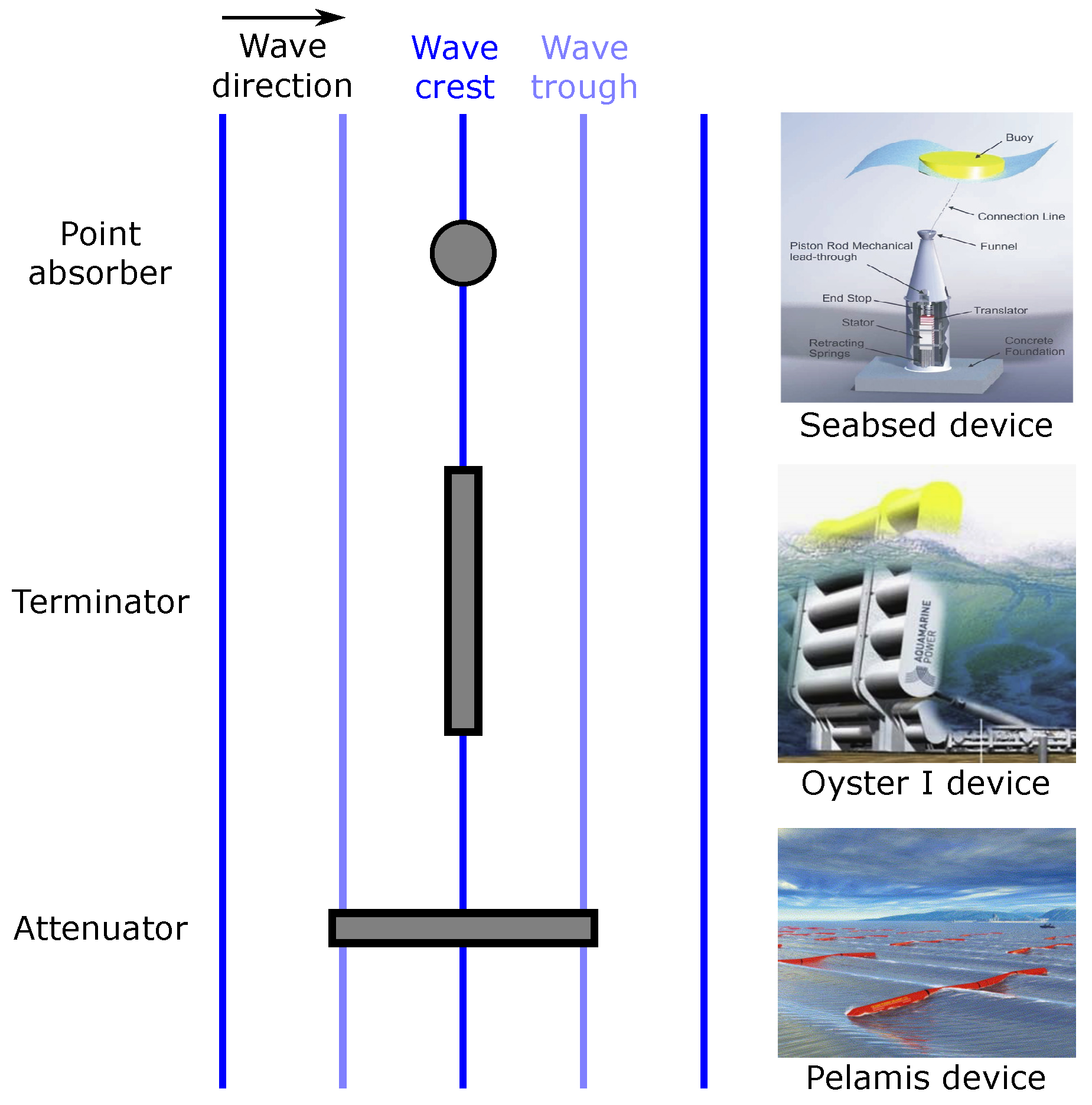
2. Point Absorber Prototypes

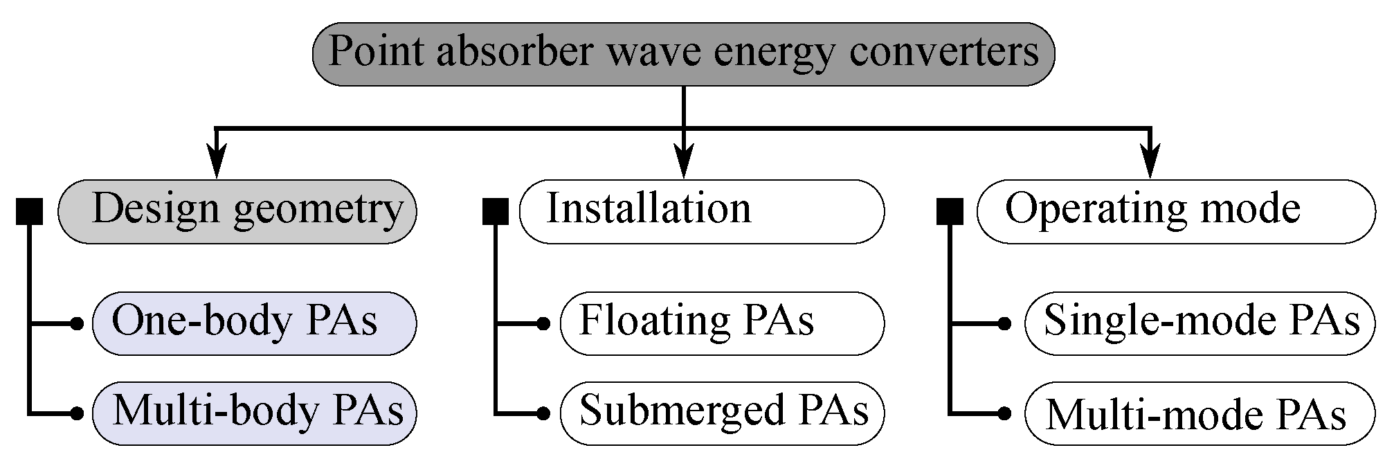
2.1. Classification of Point Absorbers

As shown in Figure 2, PAs can be further classified as (1) one-body and multi-body PAs according to design geometry, (2) floating and submerged devices, according to the deployment manner, and (3) single-DoF and multi-DoF prototypes, according to the operating DoFs. This paper uses the geometry-based classification method, and this section briefly introduces some typical prototypes of the one-body and multi-body PAs in Section 2.2 and Section 2.3, respectively. These typical prototypes, which are detailed in this section, are of a high TRL (>6) and have been experimentally tested in a representative environment (sea trail).

2.2. One-Body Point Absorbers

A one-body PA device is referenced to a fixed or absolute point (e.g., the sea bed). There are two main subtypes of one-body PAs: the floating one-body PAs and the submerged one-body PAs, as shown in Figure 3. The most notable floating one-body PAs include the Seabased device, the LifeSaver device and the CorPower device, detailed in Section 2.2.1. The AWS device and the CETO device are exemplified as the typical submerged one-body PAs in Section 2.2.2.

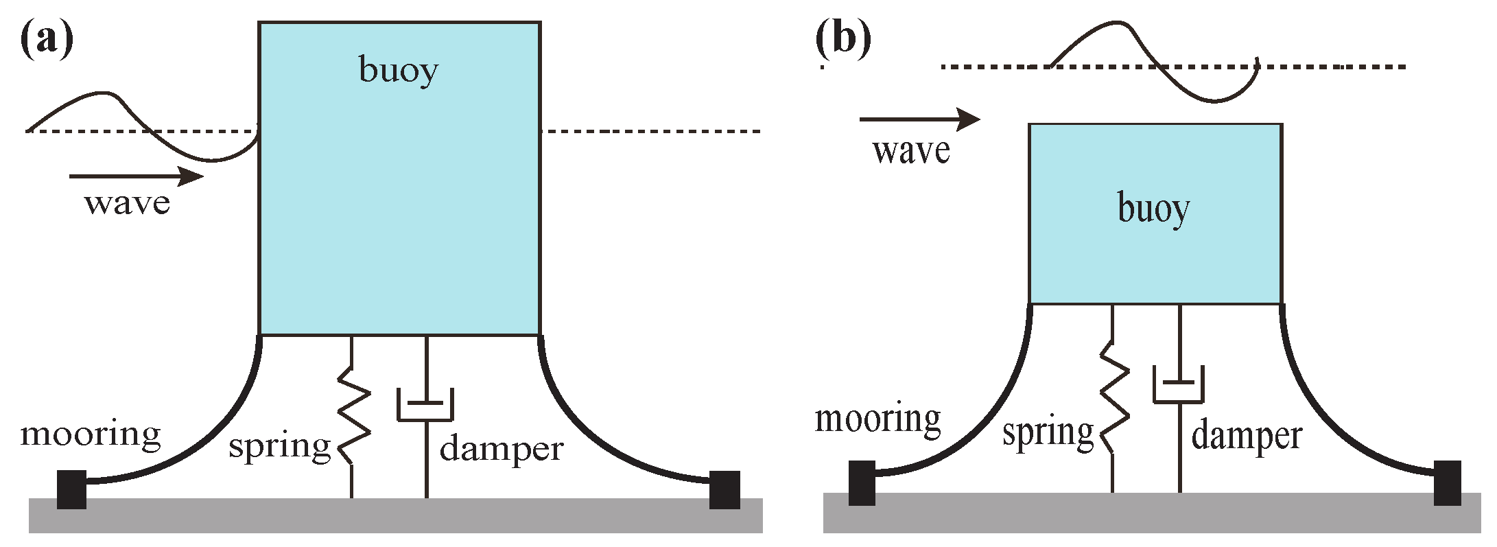
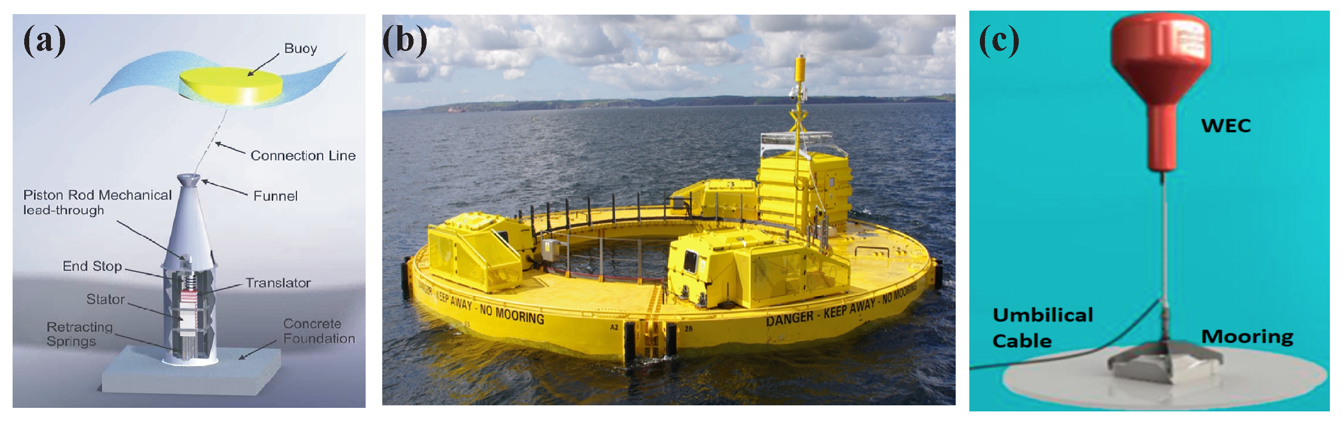
2.2.1. Floating One-Body Point Absorbers

A floating PA comprises a floating body interacting with surface waves and a PTO unit referenced or anchored to the sea bed. The floating body oscillates under the excitation of waves, and its motion drives the PTO mechanism to generate electricity. Among various floating one-body PAs, the Seabased device, the LifeSaver model and the CorPower prototype are typified in Figure 4.
The Seabased device is one of the most notable floating one-body PAs. As shown in Figure 4a, a floating truncated cylinder is used to capture wave power, and its motion drives a seabed-mounted linear generator via a rope to produce electricity [80]. Although the Seabased device oscillates in 6 DoFs, its dynamics are dominated by the heave motion, and a simplified mathematical model with heave only can give a good representation of the device’s performance [81]. At full scale, the buoy is 3 m in diameter and 0.8 m in height, with a permanent magnate linear generator rated at 10 kW [82,83]. The Seabased devices can be easily deployed to form an array. The sea trial of a small array with four devices addressed the importance of passive control in power maximisation [84], and another sea trial at Lysekil also demonstrated that PAs have a limited negative impact on the ocean environment [85].
As shown in Figure 4b, the LifeSaver device utilises a circular buoy consisting of three segments. For each segment, a PTO unit is installed and moored to the seabed via a winch line. The full-scale device has an outer diameter of 16 m, an inner diameter of 10 m and a height of 1 m, with a total rated power of 30 kW [86,87]. The mooring lines are uniquely integrated as part of the winch and rope PTO units, which can only generate electricity when the circular buoy moves upwards. Thus, the peak-to-average power ratio is as high as 60, and energy storage is required to smooth the generated power [86]. In extreme conditions, the PTO units experienced several structure failures. The redundant design in the PTO ensured the device would operate continuously in a long duration [88].
The CorPower device utilises a heaving buoy to capture the kinetic wave energy, as shown in Figure 4c. The buoy is connected to the seabed using a tensioned mooring line. Inside the buoy, a gearbox is used to transfer the reciprocating motion of the buoy into the spinning motion for a conventional generator. The full-scale CorPower C4 device in development has a diameter of 9 m, a height of 18 m and a weight of 70 tonnes, with a nominal power rating of 300 kW [89]. The CorPower device utilises a “negative” spring technology named “WaveSpring”, and tank testing demonstrated that the WaveSpring technology is able to increase power absorption by a factor of three [90].
In general, the dynamics of floating one-body PAs are of low-pass characteristics in the frequency domain, and the natural frequency and response amplitude operator (RAO) significantly rely on the geometric shape of the floating body [56]. Hence, the hydrodynamic efficiency of floating one-body PAs can be significantly improved by optimising the bottom shape [91,92]. As sea states vary from time to time, and the wave frequency is generally off the natural frequency of a PA device, it is hence important to apply control strategies to tune the device’s natural frequency towards the wave frequency for maximising the power captured [37,39,40,41,67].

2.2.2. Submerged One-Body Point Absorbers

The working principle of a submerged one-body PA is similar to its floating counterpart, and the only difference lies in the status of the body, which can stand on or anchor to the sea bed with positive buoyancy. Among various submerged one-body PAs, the famous representatives are the Archimedes wave swing (AWS) device [93,94] and the CETO (named after a Greek sea goddess) device [95], shown in Figure 5.
The AWS device consists of a bottom-fixed cylindrical chamber fully filled with air and a movable captor, which heaves due to the pressure difference induced by wave crests and troughs. The captor’s motion drives a linear generator for electricity production. The captor has a diameter of 9.5 m and a stroke of 7 m ( ± 3.5 m), and the linear generator is rated at 1 MW [33,98]. The natural frequency of the AWS device can be controlled to match the prevailing wave frequency [33,98]. Hence, various control strategies have been compared numerically, and the findings have addressed the importance of control of increasing annual energy production [99].
The CETO device uses a fully submerged buoy for wave power capture. The CETO 5 device is anchored to the seabed by a single tether, and its heave motion drives a cylinder to pump fluid to an onshore hydroelectric PTO unit [95]. Meanwhile, the CETO 6 device utilises three-tethered mooring lines to drive the mechanical PTO inside the buoy. The CETO 5 device has a diameter of 20 m, a height of 6 m and a hydraulic PTO rated at 240 kW [95], while the CETO 6 device has a diameter of 25 m, a height of 5 m and 3 mechanical PTOs rated at 1 MW [100,101]. Compared with the CETO 5 device, the CETO 6 device makes use of multiple DoFs (i.e., heave, pitch and surge) to harness more energy [102].
Compared with floating one-body PAs, submerged ones are expected to be more robust to extreme waves but less efficient. In addition, the submergence depth becomes an important factor that should be taken into account in geometric optimisation, as it significantly affects hydrodynamic performance and power capture [103].

2.3. Multi-Body Point Absorbers

Multi-body PAs can be further divided into two-body PAs and multi-point WECs, as shown in Figure 6. In general, a two-body PA is self-referenced, and its relative motion between the two bodies is utilised to drive the PTO system for electricity production. The multi-point absorber device is referred to a WEC consisting of several floaters referenced to a large offshore platform, and the floaters’ motion drives the PTO units to generate electricity. Two-body PAs can be further divided into self-reacting PAs and self-contained PAs, which are discussed in Section 2.3.1 and Section 2.3.2, respectively, while a couple of notable multi-point absorbers are detailed in Section 2.3.3.

2.3.1. Self-Reacting Two-Body Point Absorbers

A self-reacting two-body device has a floater, mainly to interact with surface waves for wave power capture, and a reacting body, mainly to provide a reference point. The relative motion between these two bodies drives a PTO system to generate electricity. The OPT PowerBuoy device [104] and the Wavebob device [105] are typified in Figure 7.
The OPT PowerBuoy device consists of a torus floater and a spar. The floater is optimised to resonantly heave up and down with surface waves, while the spar is designed to remain stationary by adding a heavy plate at its bottom. A ball-screw mechanical PTO is installed inside the spar to transfer the bidirectional relative motion of the two bodies into unidirectional rotation for a rotary generator [104,108]. For the first commercial PB3 device, the torus had a diameter of 3 m, while the spar had a diameter of 1 m. The rated power was 3 kW [104]. It is worth noting that the survivability problem was prioritised at the early stage of development, and the device response and load in 100-year storms and extreme wave conditions were studied to improve device survivability.
The Wavebob device consists of a torus and a float-neck-tank (FNT). The torus is essentially a wave follower over the range of the wave frequencies of interest for power conversion, while the FNT has a much lower natural frequency and acts as a reference for the torus [109]. The torus and the FNT are coupled via a hydraulic PTO unit or a direct-drive linear generator [107,110]. At full scale, the torus has a diameter of 17.6 m, a draft of 4.86 m and a freeboard of 3.0 m, while the FNT has a draft of 57 m [110]. A 1/4 downscaled prototype, rated at 500 kW [111], was deployed at the Galway Bay Ocean Energy Test Site in 2006, becoming the first sea-tested WEC in Ireland. It is worth noting that the Wavebob device is prone to parametric resonance in roll and pitch [105,107].
Compared with one-body PAs, two-body ones are not referenced to a fixed point. Thus, two-body PAs are suited well to deep-water applications with a proper mooring design. In the frequency domain, two-body PAs perform like bandpass filters, and their passbands can be optimised to match a certain wave climate. However, the number of design parameters is much larger than that of one-body PAs.

2.3.2. Self-Contained Two-Body Point Absorbers

A self-contained PA only utilises its hull to interact with surface waves and uses a pendulum structure to generate electricity. The notable self-contained two-body PAs are the SEAREV device with a vertical pendulum [112] and the Penguin device with a horizontal pendulum [113], as shown in Figure 8.
The SEAREV device consists of a closed floating hull in which a circular pendulum oscillates. The relative motion is used to produce electricity via a hydraulic or direct-drive PTO system. At full scale, the SEAREV device was supposed to have a length of 26.64 m, a width of 13.25 m, a height of 20.7 m, a draft of 14.6 m and a rated power up to 400 kW [112,116]. The development trajectory of the SEAREV device is detailed in [112,117], which addresses the importance of geometric optimisation and power maximisation control. In addition, parametric resonance was observed in tank testing [118], which reduced the energy production by a factor of four.
The Penguin device uses its hull to capture wave power in the pitch and roll modes, and an eccentric pendulum inside the hull directly drives a rotary generator for electric power. At full scale, the Penguin hull ranges from 30 m to 56 m, with its rated power varying from 0.5 MW to 1 MW. The LCoE was predicted to range from EUR 60 to 320/MWh [113], which is inviable in the electricity market. In addition, an acoustic noise study of the Penguin device was conducted [119] which concluded that the source sound pressure level of the Penguin device was measured to be 140.5 dB re μPa at 1 m, while the mean value of the ambient noise was 112 dB re 1 μPa. The underwater sound pressure level is expected to decrease to the ambient background noise level within approximately 10 m from the device [119]. Thus, the ecological impact on mammals (e.g., dolphins and whales) is expected to be minimal.
Different from self-reacting PAs, a self-contained PA only uses the hull to capture wave power. In terms of DoF, self-reacting PAs mainly operate in heave mode, while the self-contained ones can operate in heave, pitch or roll mode. In addition, pendulum-based WEC systems have attracted wide attention. For more information, readers are referred to the inertial sea wave energy converter (ISWEC) [120], the AMOG device [121], the pendulum wave energy converter (PeWEC) [122], the whatever input to torque transfer (WITT) device [123], the inverted pendulum wave energy converter (IPWEC) [124], etc.

2.3.3. Multi-Point Absorbers

For multi-point absorbers, a jacked-up structure or a semi-submersible platform is used to host several floating bodies to harvest wave power. The floating bodies can operate in heave, pitch and other modes. The WaveStar device [125] and the FO3 device [126] are shown in Figure 9.
The WaveStar device has a couple of spherical bottomed cylinders attached to a jacked-up frame via steel arms, and each arm utilises a hydraulic PTO or linear generator to generate electricity. At full scale, the platform is supposed to have 40 bodies. Each floater has a diameter of 5 m, the steel arm has a length of 10 m, and the power rating of each PTO unit is 55 kW [129]. Experimental tests showed that the WaveStar device was able to achieve a high hydrodynamic efficiency of up to 40–60% [127]. In extreme waves, the WaveStar device can enter into survival mode by lifting up the floating bodies. Several sea trials have demonstrated that the WaveStar device has good survivability, high reliability and limited maintenance requirements [129].
The FO3 device uses a semi-submersible platform to host several egg-shaped cylinders. Excited by surface waves, the cylinders heave up and down with respect to the semi-submersible platform, and their motion drives hydraulic PTO systems to generate electricity. At full scale, the semi-submersible platform has a length of 36 m, a width of 36 m and a height of 24 m [130]. The nominal power was estimated to be 2.52 MW when subjected to a sea state with a wave height of 6 m and a period of 9 s [130]. In addition, the LCoE is predicted to around EUR 2.8/kWh [130], which is not competitive in the utility market.
It is worth noting that the multi-point absorber device is different from the WEC array of several PAs. The multi-point absorber device has a main structure to host multiple bodies. Thus, the number and spacing of floaters are constrained by the size of the main structure. On the contrary, the number, spacing and layout of a PA array are only constrained by the area of its deployment site.

3. Hydrodynamic Modelling

In terms of PA hydrodynamic modelling, its methodology is the same as the other types of WEC devices. As there is a mass of publications dealing with WEC hydrodynamic modelling, this paper only gives a brief introduction of the PA hydrodynamic modelling. For more detailed information on hydrodynamic modelling, the readers are referred to [27,28,29,30,63,131,132,133].
In this paper, a floating cylinder in Figure 10 is given to demonstrate the hydrodynamics modelling problem of a generic PA device. The PA’s dynamics are governed by Newton’s second law as follows:
M ξ ¨ ( t ) = f h ( t ) + f g ( t ) + f pto ( t ) + f m ( t ) + f add ( t ) ,
where M is the inertial matrix of the cylinder, ξ is the floater’s displacement of the WEC, f h is the hydrodynamical force or torque, f g is the force or torque induced by gravity, f pto is the PTO force or torque, f m is the force or torque induced by the mooring system and f add represents some other additional forces or torques. The dimensions of the aforementioned parameters or variables rely on the number of PA bodies and DoFs. As shown in Figure 10, the cylinder can oscillate in six DoFs (i.e., the surge, sway, heave, roll, pitch and yaw modes).
As shown in Figure 10, the hydrodynamical force or torque is represented by the integral of the pressure p on the wetted surface S, written as
f h , i = S p n d S , i = 1 , 2 , 3 , S p ( r × n ) d S , i = 4 , 5 , 6 ,
where n is the normal vector on the wetted surface and r is the vector from the reference point to the wetted surface. i = 1 , 2 , 3 6 indicates the DoFs of surge, sway, heave, roll, pitch and yaw, respectively. For simplicity, n h = [ n , r × n ] is defined, and Equation (2) can be simplified as
f h = S p n h d S .
The key for PA modelling is to compute the hydrodynamic force f h , and the hydrodynamic modelling methods are summarised in Figure 11, which can be divided into numerical and experimental methods. Numerical methods are generally used to solve the Navier–Stokes equations to obtain the pressure field in the fluid. Hence, the hydrodynamic force or torque can be computed according to Equation (3). Furthermore, the numerical methods can be further classified into three subtypes: the computational fluid dynamics (CFD) methods, the potential flow theory (PFT) methods and the hybrid methods. In addition, experimental testing is generally applied to collect data for deriving or identifying PA models. The aforementioned modelling methods are discussed below.

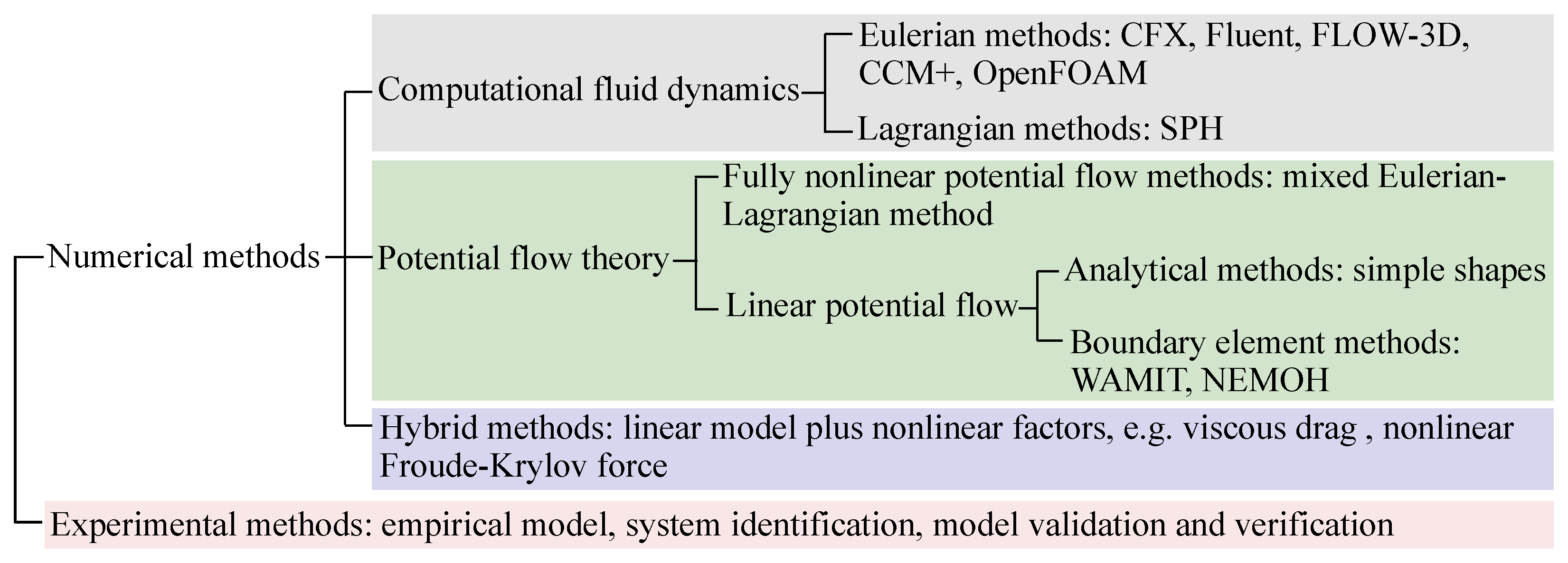
3.1. Computational Fluid Dynamics Methods

CFD methods are broadly used in modelling WEC hydrodynamics due to their capability to provide high-fidelity results and to capture highly nonlinear phenomena [29]. Currently, the Navier–Stokes equations cannot be solved analytically, and CFD methods can provide relatively accurate numerical approximations by computing the pressure and velocity field in the fluid. Thus, the hydrodynamic force can be calculated according to Equation (3).
CFD methods include the Eulerian and Lagrangian methods. The Eulerian methods discretise the fluid into small cells, while the Lagrangian approaches discretise the fluid as a set of particles. Most CFD software packages follow the Eulerian methods, and the notable ones include ANSYS Fluent, CFX, FLOW-3D, Star-CD/CCM+ and OpenFOAM. Those packages are broadly used for PA modelling since they are capable of handling various nonlinear PA hydrodynamics (e.g., viscosity [92,134,135], vortex shedding [136,137], overtopping [138,139] and slamming [138]). Among several Lagrangian methods, the smoothed particle hydrodynamics (SPH) method is investigated intensively, and the DualSPHysics, an open-source SPH package, is available online [140]. The SPH method shows advantages in the automatic conversion of mass and simplification of surface tracking, and hence, it can easily compute the wave load of PA devices in extreme waves [141,142].
Compared with the other modelling methods, the CFD methods have the following advantages: (1) CFD methods are more cost-effective than experimental methods. (2) CFD methods can give more accurate results than those of PFT methods, especially when nonlinear phenomena are considered, and (3) CFD can ease the modification of WEC for parametric study. Meanwhile, CFD methods may be unsuitable in some scenarios due to their drawbacks, which are as follows: (1) CFD software packages are unfriendly to new learners and may take some time to get started, (2) it is complex to set CFD modelling parameters and boundary conditions properly, and an improper configuration may result in modelling results away from reality. Thus, experimental validation is required. Finally, (3) CFD modelling requires a huge amount of computing power, which has been satisfied by the rapid development of computer science.

3.2. Potential Flow Theory Methods

By assuming that the fluid is ideal, the Navier–Stokes equations can be simplified to the Laplace and nonlinear Bernoulli equations, and the fully nonlinear potential flow theory (FNPFT) is developed to solve the Laplace and nonlinear Bernoulli equations. By further assuming that the wave steepness is small, the nonlinear Bernoulli equation can be simplified, leading to the linear potential flow theory (LPFT). As the FNFPT and LPFT use a potential function ϕ to obtain the pressure field p in the fluid, they both belong to the potential flow theory.
The FNPFT only assumes the fluid is incompressible, inviscid and irrotational. Hence, it can handle nonlinear and steep waves as well as large body oscillations. Currently, there is no such universal software package for solving the Laplace and nonlinear Bernoulli equations, but there are some trials for WEC modelling. By further assuming that the motion of a floater is small, the wetted surface can be treated as invariant, the normal vector n h can be computed at the equilibrium point of the floating body, and the wave–buoy interaction can be linearised at the equilibrium point. Based on the LPFT, the potential function can be divided into incident, diffracted and radiated components [143] as follows:
ϕ = ϕ i + ϕ d + ϕ r ,
where ϕ i is the incident potential function determined by the incident wave when the floating body is absent, ϕ d is the diffraction potential function, assuming the body is stabilised at the equilibrium point, and ϕ r is the radiation potential function, assuming the floater oscillates in still water. Thus, the pressure field is given by
p = ρ g z ρ ϕ t ,
where ρ is the water density, g is the gravitational constant, z is the vertical position (to see Figure 10) and t is the time. Hence, the hydrodynamic force f h can be rewritten as
f h = f FK + f d + f r + f hs ,
f FK = ρ S ϕ i t n h d S ,
f d = ρ S ϕ d t n h d S ,
f r = ρ S ϕ r t n h d S ,
f hs = ρ S g z n h d S ,
where f FK is the Froude–Krylov (FK) force, f d is the diffraction force, f r is the radiation force and f hs is hydrostatic force.
In general, the buoyancy of a floating buoy in still water is neutral, and hence, f hs + f g = 0 holds. When the floating body deviates from the equilibrium point, there will be a mismatch between the buoyancy and gravity, which provides a restoring force or torque in the heave, roll and pitch modes. For the case where f hs + f g > 0 , the positive buoyancy should be balanced by a pretensioned mooring design.
In addition, the summation of the incident problem ( ϕ i ) and the diffraction problem ( ϕ d ) is called the excitation problem, and the excitation force is given as f e = f FK + f d . For linear wave theory, an analytical solution for ϕ i exists. The analytical solutions for ϕ d and ϕ r only exist for some simple and basic geometries (e.g., a truncated floating cylinder) [144,145].
For a floating body with an arbitrary geometry, the ϕ d and ϕ r are difficult to solve analytically, and the boundary element methods (BEMs) are broadly applied to provide numerical approximations. Based on two one-body PAs, one with a spherical floater and the other with a cylinder-cone floater, a comparison study for evaluating the aforementioned modelling methods was conducted under the framework of the OES Wave Energy Conversion Modelling Task, which concluded that the linear, weakly nonlinear and fully nonlinear methods give similar results for experimental data for small and medium wave conditions [131]. This is the rationality for using LPFT methods to model PA hydrodynamics in operation mode. Thus, BEM solvers (WAMIT, NEMOH, AQWA, etc.) are generally used for PA hydrodynamic modelling.
Compared with the other modelling methods, the PFT-based methods are of high computational efficiency. Thus, both the FNPFT-based and LPFT-based methods work well for PA design at low TRLs and performance evaluation over a long duration. However, the assumptions of an ideal fluid, small wave amplitude and small body motion can seldom be met. Hence, the modelling fidelity is doubtful, especially when PAs are tuned to resonance by control.

3.3. Hybrid Modelling Methods

As mentioned above, the LPFT-based BEM solvers assume the fluid is ideal, the wave height is small, and the body motion is small. However, the motion of a PA device can be significantly amplified by power-maximising control, resulting in some important nonlinear factors (e.g., nonlinear viscous force [134] and nonlinear FK force [146,147]).
To treat some key nonlinearities, hybrid modelling methods are developed to augment the LPFT-based Cummins’ equation. Thus, the concepts of excitation and radiation hold, and the Cummings’ equation [148] can be written as
( M + M ) ξ ¨ ( t ) = f e ( t ) K ξ ( t ) k r ( t ) ξ ˙ ( t ) + f pto ( t ) + f m ( t ) + f nl ( t ) ,
where M is the added mass, K is the hydrostatic stiffness, k r is the radiation kernel function and f nl is the treated nonlinear force. In general, nonlinear treatments can be classified as the following four types:
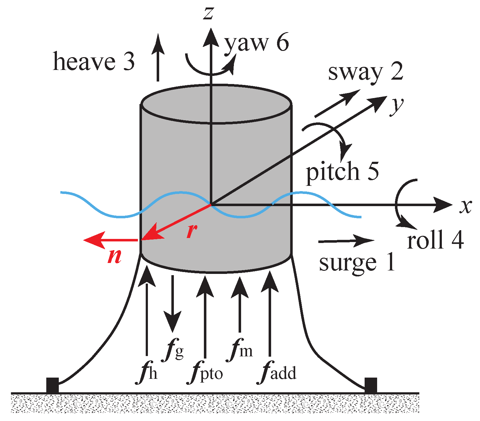
  • For the body-exact treatment method, the instantaneous body position is considered in computing the FK, diffraction, radiation and restoring forces in Equations (7)–(10), while the wave is still assumed to be small. When the body size is small, the nonlinearity in diffraction and radiation are neglectable. For a body with a varying horizontal cross-section, the nonlinearity in the hydrostatic force appears obvious. Considering the large body motion, the nonlinearity in the FK force is more critical than the other force and has a significant impact on PA hydrodynamics [146,149,150].
  • For the weak scatterer treatment method, the instantaneous free surface is considered in computing the forces in Equations (7)–(10), while the wetted surface is linearised at the equilibrium point. This method linearises the free-surface boundary condition at z = η ( t ) . Thus, the second-order terms of ϕ d and ϕ r can be added to compute the diffraction and radiation forces in Equations (8) and (9). However, the importance of the nonlinear diffraction and radiation terms mainly depends on the body size. For a small body, these nonlinear forces can be neglected [151].
  • For the viscosity treatment method, the viscosity is considered by adding a quadratic term to the Cummins’ equation, according to the Morison equation [152]. This method can significantly improve the modelling accuracy with little computing cost when the relative velocity between the body and fluid is large. The viscous coefficient can be determined analytically, numerically or experimentally [134,153,154]. However, a wide range of wave conditions should be tested to obtain a consistent value [155].
  • The mixed treatment method has two subclasses: the body-exact viscosity treatment considering both large body motion and fluid viscosity and the weak-scatter viscosity treatment considering both a large wave height and fluid viscosity. In AQWA, the weak-scatter viscosity treatment is realised by computing the nonlinear FK and hydrostatic forces according to instantaneous wave elevation and adding the viscous force according to the Morison equation [156,157]. In general, PAs’ motion is significantly amplified by power maximisation control, and hence, the nonlinearity induced by large body motion is more critical than that induced by a large wave height. Therefore, the body-exact viscosity treatment is broadly used in PA modelling.
The four types of hybrid modelling methods can achieve a trade-off between modelling fidelity and computational efficiency. However, they can only handle some “weak” nonlinearities induced by a large motion, large wave or viscosity. In addition, the determination of critical nonlinearities is not unique and should be conducted in a case-by-case manner. To capture all kinds of nonlinear phenomena, CFD and experimental methods are recommended.

3.4. Experimental Modelling Methods

Downscaled PA prototypes are generally used for tank testing to investigate PA dynamics in a more real scenario. The collected data are used to verify or validate the aforementioned modelling methods. On the other hand, the collected data can be used to identify PA models in a data-driven manner. For scaling down a PA prototype, the Froude number is used to ensure the kinematic and dynamic similarities of the prototype with respect to those of its original model [132]. Thus, the PA hydrodynamics and power capture can be easily scaled up.
For identifying empirical or data-driven models of PA devices, numerous tank tests are required to cover a wide range of wave conditions in order to depict all possible hydrodynamics that a PA device may come across in reality. Data-based modelling from physical experiments has been applied to derive mathematical models for various WEC systems [158,159,160,161,162]. In addition, experimental data can be used to identify the viscous coefficient [134,155,163,164,165].
Strictly speaking, open sea testing in a wide range of sea states is the “gold standard” for verifying and validating modelling methods. However, it is extremely costly and time-consuming, even if downscaled prototypes are used. In addition, numerical modelling methods can provide a fully controlled environment, which offers an easy, economical and flexible way to adjust the PA design and wave conditions.

4. Power Take-Off Mechanisms

For a PA device, the PTO mechanism is one of the most important components which generates electric power and, simultaneously, works as an actuator for control implementation. In the literature, several review papers on PTO have been published, and readers are referred to [35,36,166,167,168,169]. This paper only focuses on the PTO systems related to PA devices, classified as (1) hydraulic PTOs [34,170,171,172,173], (2) mechanical PTOs [174,175], (3) direct-drive PTOs [176,177,178] and (4) some novel PTOs [179,180], as shown in Figure 12. These PA-related PTO mechanisms are discussed below.

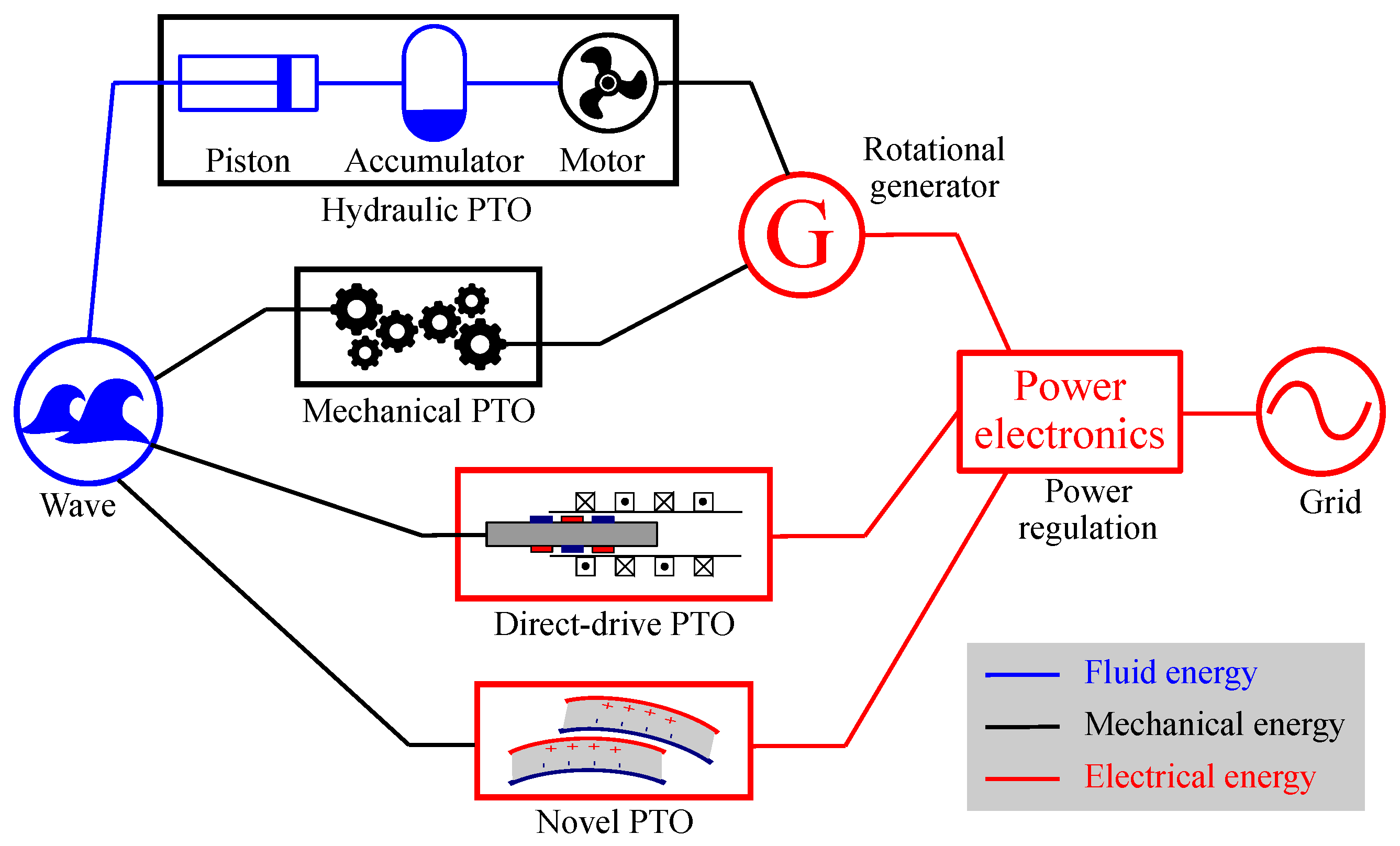
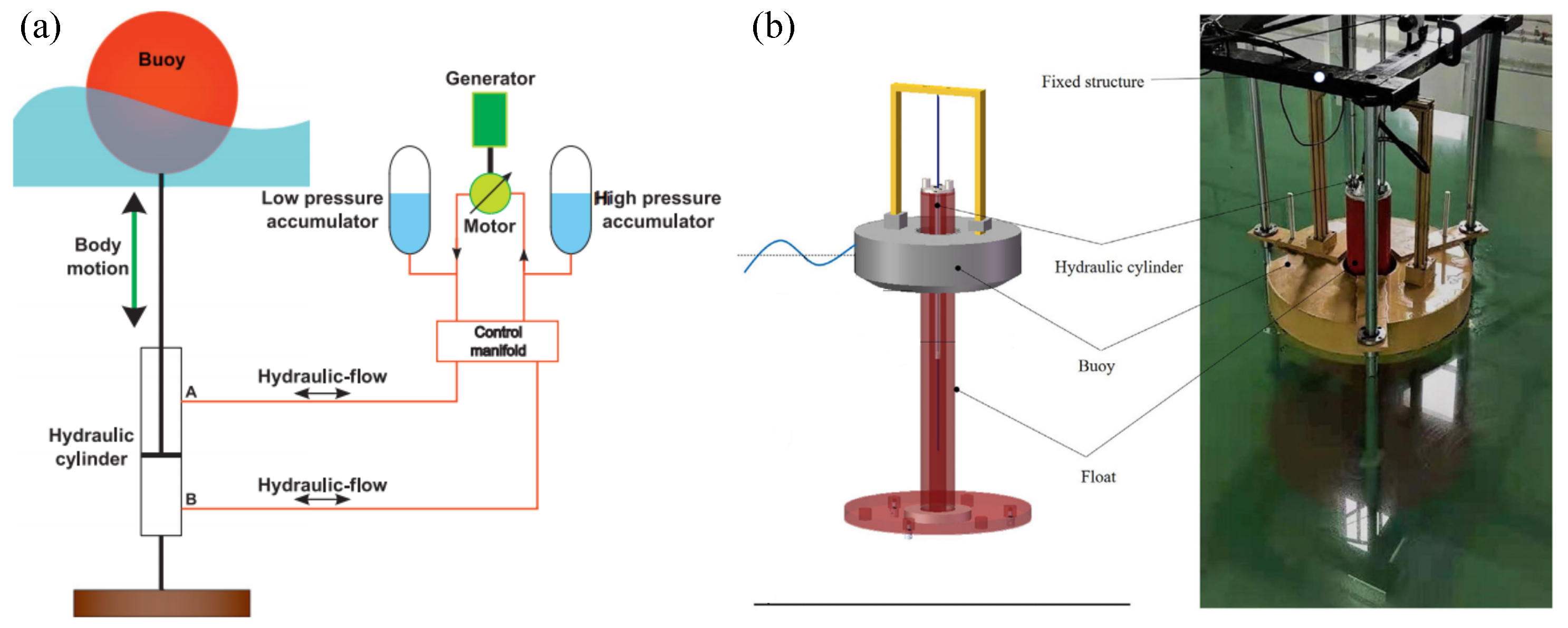
4.1. Hydraulic PTO Mechanisms

The hydraulic PTO mechanism is the most mature one for wave energy conversion, comprising hydraulic cylinders, pipes, regulating valves, accumulators, hydraulic motors, rotary generators, etc. The working principle and a case study of hydraulic PTO systems are shown in Figure 13.
Compared with the other PTO mechanisms, the hydraulic PTO has shown some unique advantages: (1) The hydraulic technology is mature and broadly used in the industrial sector [31]. Thus, all the hydraulic components are market-accessible, and the accumulated O&M experience is portable for PA applications. (2) Hydraulic systems are capable of providing a large force at a low speed, and this feature suits the wave energy application scenarios well since wave force has a large amplitude and a low frequency [55,182]. That is why the hydraulic PTO mechanism is preferred by WEC developers. (3) Hydraulic PTO systems can be feasibly and flexibly used for a variety of PA devices regardless of the operating DoFs, installation manners or geometries [34]. Finally, (4) with the assistance of the regulating valves and accumulators, a hydraulic PTO system is able to overcome the variation in wave power and provide stable electrical power.
However, the application of the hydraulic PTO mechanism for PA devices is constrained by some drawbacks: (1) Compared with the other PTO systems, the overall efficiency of a hydraulic PTO system is low, mainly due to the friction and viscous loss in the hydraulic system [183]. A case study based on a hydraulic PTO for a WaveStar-like device showed that the friction loss was almost as large as the generated electrical power [173]. In addition, the energy conversion steps are complex [184]. (2) In general, a hydraulic PTO system requires regular maintenance, and hence, the O&M cost may be high, considering the harsh offshore environment. As reported in [31], the hydraulic oil should be replaced after some thousand hours of operation; that is, the hydraulic oil should be refilled once or twice a year. Finally, (3) there exists a pollution risk as hydraulic oil is used. Thus, it is challenging to seal a hydraulic PTO system in an effective and efficient manner [53].
From the viewpoint of control, the properties of hydraulic PTO systems are manifold. Some control strategies (e.g., latching, declutching and bang-bang control approaches) can be easily realised by hydraulic PTO systems [55,185]. On the other hand, the features of hydraulic PTO units also limit the control strategies in the discrete time domain [31]. More hydraulic rams and accumulators are required to smooth out the control performance, which will increase the system complexity significantly.

4.2. Mechanical PTO Mechanisms

Mechanical PTO systems are broadly used in PA devices. For instance, a rack and pinion mechanism is used by the CorPower device, belt drive mechanisms are used by the LifeSaver device and the CETO 6 device, and a ball screw mechanism is used by the OPT PowerBuoy device in order to convert reciprocating motion to rotation for driving rotary generators. To demonstrate the working principle of the mechanical PTO mechanism, a ball screw unit is shown in Figure 14.
Compared with the other PTO mechanisms, the mechanical PTO mechanism shows some technical advantages: (1) The mechanical transmission is mature and broadly applied in industrial applications. (2) In general, the energy loss of a mechanical PTO system is low, and the efficiency of a mechanical transmission system is high. For instance, a rack and pinion mechanism can achieve an efficiency up to 97% [61]. Lastly, (3) a variety of mechanical transmission mechanisms provides flexible means to regulate the reciprocating motion of WEC bodies into unidirectional rotation, which is more friendly for driving conventional rotary generators.
However, there are still some drawbacks that hinder the commercial application of WECs with mechanical PTO systems: (i) The mechanical transmission systems suffer from a fatigue problem, and they are prone to structure failures. Their reliability and lifespan should be improved. (2) In general, a mechanical PTO system itself is complex. Considering the dynamics of a mechanical PTO system, the complexity of a PA device will be critically high. (3) The mechanical PTO systems suffer from various nonlinear dynamics (friction, backslashing, etc.). Finally, (4) regular O&M work is required (e.g., lubrication) to keep the mechanical PTO systems operating under an ideal condition.
As the mechanical PTO systems are capable of changing linear motion to rotational motion, they show promising potential for easing the connection of generators. However, a mechanical PTO unit may toughen the implementation of some control strategies. For instance, the mechanical motion rectifier in Figure 14 does not easily permit reactive power flow, which hinders the application of reactive control [174,186].

4.3. Direct-Drive PTO Mechanisms

Direct-drive PTO systems have been successfully used for wind turbines, and some experience is portable for WEC devices. The permanent magnet linear generator (PMLG) concept was proposed in [187] to produce electrical power from sea waves. A PMLG, as shown in Figure 15, was designed and tested in [33,98,188,189,190] as PTO mechanisms for the AWS device [93,94] and the Seabased device [82,83]. A variety of PMLGs was compared in [178,182,191,192]. In addition, a rotary generator is used as the direct-drive PTO system for the Columbia Power PA device [193].
Compared with the other PTO systems, the main advantages of the direct-drive PTO units are as follows: (1) The direct-drive mechanism can provide high efficiency, since it can convert the buoy motion into electricity directly with only two energy conversion stages [55,191]. (2) The reliability is expected to be high since a direct-drive PTO unit compromises fewer components. (3) The maintenance requirement is low, maily due to its simple topological structure [31]. (4) The direct-drive PTO system is feasible for control via electrical approaches, which have been generally used in the electricity industry [195]. Lastly, (5) direct-drive PTO systems can operate reliably, even when the peak-to-average power ratio is up to 20 [196,197].
On the other hand, the drawbacks of direct-drive PTO systems are as follows: (1) The power or force density is low, and hence, the PTO volume and weight should be large enough to achieve a certain power rating [13,55], and (2) the manufacturing cost of a direct-drive PTO system is relatively high compared with the hydraulic PTO systems due to the high cost of the permanent magnets [182]. The permanent magnet materials have advanced significantly, resulting in a larger force density and a lower cost [33]. However, the force density and manufacturing cost of direct-drive PTO systems are still relatively higher those that of hydraulic PTO systems.

4.4. Novel PTO Mechanisms

For the past decade, some novel materials have been used for WEC applications (e.g., dielectric elastomers and triboelectric materials). The dielectric elastomer, also called the electroactive polymer artificial muscle, can be used as a PTO mechanism for WEC devices, named a dielectric elastomer generator (DEG). The working principle of the DEG is shown in Figure 16. The DEG can convert mechanical transformation into electrical energy from the stretched and released four-phase cycle. For more information, readers are referred to [198,199].
The main advantages of the DEG technology are the following: (1) A DEG can be easily controlled in an electrical manner. Thus, it can operate partially as a generator and partially as an actuator. (2) The conversion efficiency of a DEG is relatively high, with a theoretical value of up to 80–90% [200]. In practical applications, its achieved conversion efficiency was 70–75% [201]. In addition, (3) the conversion efficiency is not sensitive to the frequency, and hence, a DEG is well suited to irregular waves. Finally, (4) the material is flexible and environmentally friendly [202].
On the other hand, the DEG technology suffers from some drawbacks: (1) The DEG technology is untapped, at least for wave energy, and more testing is required. (2) It is difficult to design the coating and sealing for a DEG PTO unit [203]. (3) For a certain rated power, the DEG volume is much larger than that of the other PTO systems [202]. In turn, the complexity of a WEC geometric design and optimisation increases dramatically. Lastly, (4) the rubber-like material shows high nonlinearity in its dynamics and suffers from fatigue and durability problems [180].
More recently, a new energy conversion technology, called the triboelectric nanogenerator (TENG), has been used for wave energy harvesting. As shown in Figure 17, a torus-shaped point absorber with a movable ball inside is used for triboelectric power generation. In addition, this kind of point absorber can be easily extended to form an array [179]. As there are only a few tests on TENGs for wave energy conversion, the advantages and drawbacks are not discussed in this paper.

5. Control Strategies

Ocean waves show a high irregularity in direction, amplitude and frequency, while WEC devices are designed to operate efficiently under certain conditions. Thus, it is essential to adjust the WEC dynamics according to the time-varying wave conditions by a variety of power maximisation control strategies, including reactive control [57], phase and amplitude control [143], optimisation-based control [39] and adaptive control [204,205]. As there are several review papers dedicated to WEC control (see [37,39,40,41]), this paper only gives a brief overview of PA-related control approaches.

5.1. Classical Control Strategy

By assuming the wave is harmonic, the wave–buoy interaction is linear, and the PTO is as ideal as a mass-spring-damper system, the resonant concept for power maximising control of WEC systems was first proposed in 1975 [57,143]. Thus, Cummins’ equation in Equation (11) can be rewritten as
V ( ω ) F e ( ω ) + F pto ( ω ) = 1 Z i ( ω ) ,
where V ( ω ) , F e ( ω ) and F pto ( ω ) are the body velocity, excitation force and PTO force in the frequency domain, respectively. ω is the circular frequency. Z i ( ω ) is defined as the intrinsic impedance [143], written as
Z i ( ω ) = B r ( ω ) + j ω M + M a ( ω ) K / ω 2 ,
where B r ( ω ) and M a ( ω ) are the radiation damping coefficient and added mass to represent the radiation effect in the frequency domain.
According to the maximum power transfer theorem, the optimal PTO impedance should meet
Z pto ( ω ) = B pto ( ω ) + j ω M pto ( ω ) K pto ( ω ) / ω 2 = Z i ( ω ) ,
where Z pto ( ω ) , B pto ( ω ) , M pto ( ω ) and K pto ( ω ) are the PTO impedance, damping coefficient, mass and stiffness, respectively. Thus, the power absorbed by the PTO is maximised when the PTO impedance Z pto is the complex conjugate of the intrinsic impedance Z i . Thus, a control strategy that follows the philosophy of Equation (14) belongs to the so-called complex conjugate control category [143]. As complex conjugate control allows bidirectional power flow in the wave energy transformation chain, it is also called reactive control (RC), meaning that the PTO unit feeds power into the WEC body during a part of the wave period. However, some PTO mechanisms can only provide unidirectional power flow. For instance, a pure damper cannot feed any power back to WEC systems, and the reactive control degenerates to the so-called passive control (PC), given as
B pto ( ω ) = | Z i ( ω ) | .
For reactive control, Equation (14) holds. Thus, the optimal body velocity can be written as
V opt ( ω ) = F e ( ω ) 2 B r ( ω ) .
That is to say, the absorbed power by the PTO is maximised under the conditions that (1) the amplitude of the body velocity is proportional to the amplitude of the excitation force and (2) the body velocity is in phase with the excitation force, given as
V opt ( ω ) | = | F e ( ω ) | 2 | B r ( ω ) | ,
V opt ( ω ) = F e ( ω ) 2 B r ( ω ) .
Thus, Equations (17) and (18) are called the amplitude and phase conditions, respectively. A control strategy to achieve Equations (17) and (18) belongs to the amplitude and phase control categories [143]. In practice, the amplitude condition in Equation (17) can be realised by selecting a suitable damper, while the phase condition can be realised by latching control (LC) [143] or declutching control (DC) [206].

5.2. Modern Control Strategies

The power-maximising control laws in Equations (13)–(18) are derived under harmonic wave conditions. In practice, ocean waves are irregular and panchromatic, and the RC, PC, LC and DC approaches cannot be used directly. Thus, a variety of R&D activities has been conducted to extend the application scenarios of the classic control strategies to irregular waves. In general, the extended control strategies follow two philosophies, shown in Figure 18: the approximate complex conjugate (ACC) and approximate velocity tracking (AVT) frameworks [41]. The ACC framework can optimise the PTO set-ups according to the prevailing frequency of irregular waves, but extra efforts are required to implement physical constraints. On the contrary, the AVT framework shows more flexibility in handling physical constraints by formulating the power maximisation problem as a constrained optimisation problem. However, such a framework needs the current or future information of the excitation force. As the excitation force cannot be measured directly for an oscillating body, extra estimators or predictors are required [207,208,209,210,211].
The AVT-based control is broadly used for WEC devices, and the power maximisation control is formulated as a constrained optimisation problem, written as
min f pto 0 T f pto ( t ) v ( t ) d t s . t . ξ ( t ) ξ max , f pto ( t ) f max ,
where ξ max is the displacement constraint, mainly determined by the WEC geometric design, and f max is the PTO force limit, mainly depending on the PTO absolute parameters. Based on this optimisation formulation, several optimal control algorithms are summarised in [39]. As power-maximising control is a general problem for all kinds of WEC devices, it has been intensively investigated, and several reviews have been published. For more specific information, readers are referred to [37,38,39,40,41].

6. Discussion

This section discuses some perspectives of PA concepts, hydrodynamics, PTO, control and applications, which are detailed below.

6.1. Perspectives on PA Concepts

For a specific site, the selection of PA types is determined by the site’s environmental conditions (depth, distance from the coast, wave climate, etc.) and application scenarios. One-body PAs fit well with nearshore applications, as they are referenced to absolute points. For seas of low power densities, the floating one-body PAs are preferred, while the submerged ones are preferred in harsh seas since the floating one-body PAs are more efficient, and the submerged ones are less prone to extreme wave loads. For deep sea applications, two-body PAs are preferred, as they are self-referenced. To achieve a large installation capacity and smooth power production, multi-point absorbers are preferred. Multi-point absorbers with a jacked-up structure can only stand in shallow waters, while ones with a semi-submerged platform can operate in deep seas. It is worth noting that the system complexity increases dramatically from one-body PAs to multi-point absorbers.
In terms of the operating mode, there is a trend of harnessing wave power in multiple DoFs. To date, most PA devices operate in a single-mode manner, mainly in heave or pitch, as their modelling, control, design, manufacturing and deployment are simple, but the efficiency may be low. In order to harvest as much power as possible, several studies have shown that a multi-DoF PA device can extract more energy than its counterpart of a single DoF [102,103,135,212]. However, the hydrodynamics become much more complex, and attention must paid to the coupling between different DoFs. If the behaviour of each mode is not designed properly, the captured power may reduce severely [135,163]. In addition, the coupling between different DoFs may induce rich and complex nonlinear phenomena, such as parametric resonance in roll or pitch [105,107,213,214].
Recently, several novel PA concepts have been proposed, and some representatives are shown in Figure 19. A guided inclined point absorber was developed to increase the power capture by optimising the inclination angle [215], as shown in Figure 19a. Both numerical and experimental studies show that the guided PA with an optimised angle (ranging from 30° to 60°) are capable of harvesting more power than its vertically heaving counterpart (90°) by a factor of up to 4.52. Similar results have been obtained for the CECO device [216,217], as both the heave and surge DoFs are used for energy harvesting. In addition, both numerical and experimental studies have shown that the performance of the CECO device, as a representative of the sloped type, is significantly influenced by, for example, the wave climate [218], water depth [219], geometric design [220,221] and control design [222].
As shown in Figure 19b, five heaving PAs situated inside a moonpool struture form a multi-point absorber [223,225]. By properly optimising the moonpool dimension, PA number and spacing, the moonpool’s resonance and the interaction between PAs can significantly improve the overall energy generation. In Figure 19c, a novel heaving PA is shown. A floating sphere heaves subjected to incident waves, and the heaving motion drives two underwater impellers. Each impeller has blades, which can swing as the sphere heaves. Thus, the reciprocating motion is transferred to unidirectional rotation for generating electricity. To some extent, the working principle of this novel device is close to that of a wave glider.

6.2. Perspectives on PA Hydrodynamics

Four categories of hydrodynamics modelling methods are discussed in Section 3, and the selection of modelling methods is determined by the purposes of modelling rather than the PA types. To capture all kinds of nonlinear wave–buoy interaction, CFD methods are preferred. To evaluate or optimise PA performance in a wide range of sea states (e.g., annual energy production), LPFT-based methods can give preliminary results. If only some weak nonlinearities are non-negligible, FNPFT-based methods and hybrid methods can both give accurate approximations. For the purpose of control, none of the modelling methods can be used directly. System identification and simplification are required to derive accurate and effective transfer functions or state-space models for control design. In addition, all the aforementioned modelling methods should be verified or validated by experimental testing in the representative environment.
Currently, the LPFT-based BEM methods are the most widely used. However, there is a trend to consider nonlinearity in hydrodynamic modelling by considering the nonlinear viscous, hydrostatic and mooring properties, end-stop forces and even extreme wave loads. In addition, the operation of PA arrays has been attracting broad attention. Thus, the nonlinear hydrodynamics, extreme wave load and array operation are discussed below.

6.2.1. Nonlinear Hydrodynamics

In general, PAs with sharp edges suffer from the viscosity, especially when the relative velocity between the body and water particles is large [134,135,153], and the viscous loss can be attenuated by optimising the hull shape [56,92]. PA devices with varying cross-section areas (e.g., floating spheres) are prone to nonlinear hydrostatic force [151,226], and PAs with significantly varying wetted surfaces (e.g., floating spars) are prone to nonlinear FK force [146,147,149,150]. In extreme waves, PAs also suffer from overtopping and slamming [138,227], nonlinear mooring force [228], end-stop force [229,230,231,232], etc.
Since PAs operating in multiple modes have been attracted an increasing R&D focus, the nonlinear interaction between different DoFs has been studied in several papers. For the CETO-like device, subharmonic excitations were found in numerical simulations to illustrate the nonlinear couple between the heave and surge DoFs [135]. Another notable piece of evidence to show nonlinear coupling between different DoFs is the parametric resonance, which was observed in both numerical and experimental studies of PA devices [105,213,214,233,234,235]. A large heave motion may make the PA’s metacentric height change periodically, leading to a periodic variation in pitch or roll restoring stiffness, which excites the pitch or roll modes, inducing Mathieu instability [236]. The onset conditions of parametric resonance are complex and significantly rely on the mass distribution [237], mooring configuration [238,239], hull geometry [235,240] and hydrodynamic modelling methods [107,233,235,241,242]. For the viewpoint of hydrodynamics, the nonlinear interaction between different DoFs or modes can be modelled well using CFD methods [235] and the hybrid modelling methods considering nonlinear FK force [107,150,242].

6.2.2. Extreme Wave Loads

Several WEC structure failures were reported [50], which suggests that the survivability problem seems more important than the efficiency problem. For the past decade, several studies have been dedicated to PAs’ survivability in extreme waves, and some typical cases are shown in Figure 20. Extreme waves (e.g., the 100-year wave) are generally used for PA design to predict the extreme motions and loads exerted on the structure, PTO and mooring systems.
As shown in Figure 20a, 100-year extreme waves at the Humboldt Bay site in California were used to investigate the extreme response of a Seabased-like device via OpenFOAM [139], and it was concluded that the wave steepness and the wave length play important roles in extreme response. As shown in Figure 20b, a focused wave group was used to obtain the maximum PTO extension, heave and surge motions of CETO-like devices both in experiments and simulations [95,243]. In addition, the survivability of a WaveStar-like device was numerically and experimentally tested by being subjected to focused wave events [244,245], as shown in Figure 20c. The WaveStar-like PA may experience various extreme motions (e.g., fully submerging, slamming or overtopping).
The survivability of PAs in extreme waves is one of the most important and challenging problems. Currently, numerical experiments (e.g., CFD simulation) are used to investigate extreme wave loads of PAs for load mitigation [141,142,246]. A good example is given by the OPT PowerBuoy PB150 device, which uses 100-year storms to optimise its design at the early stage of development [104,247]. As a consequence, the PB150 device survived Hurricane Irene in 2011 [104,247].

6.2.3. Array Operation

For commercial applications, a large number of WEC devices are installed to form a WEC array, which is expected to reduce the LCoE by sharing the infrastructure and O&M service. In addition, a WEC array can smooth the power output to ease the grid connection. Based on PA concepts, the constructive park effect was first proposed in 1981 [70], and several studies were devoted to optimising the PA array’s layout [248,249,250,251,252,253,254,255,256,257,258]. These studies are mainly based on linear hydrodynamics modelling methods, and the nonlinear interaction between PAs are neglected.
Recently, CFD methods with experimental validations are capable to provide high-fidelity modelling for WEC arrays with a large number of devices, since commutating power advances rapidly. A example is shown in Figure 21, in which physical and numerical models of a PA array with up to 25 heaving devices are tested to understand array interactions. Numerical results show a high accordance to experimental data, demonstrating the capability of CFD methods for accurately modelling large PA array.

6.3. Perspectives on PA PTOs

Four types of PA-related PTO mechanisms were detailed in Section 4, of which the hydraulic and mechanical PTOs can be used for all types of PAs, while the direct-drive PTO fits well with PAs mainly operating in heave. In theory, PTO systems can be assumed to be ideal and simplified as mass-spring-damper systems. In practice, PTO systems have their own dynamics and suffer a variety of nonlinearities. Hydraulic PTOs are prone to delays, dead zones, hysteresis effects [184], etc., mechanical PTOs suffer from friction, saturation [173], etc., and direct-drive PTOs are subjected to cogging force [261], load effects [262], etc. Neglecting the dynamics and nonlinearities in PTOs may lead to improper PA design. In addition, PTOs are designed to operate efficiently under certain conditions. As waves vary all the time, PTOs seldom operate under their rated conditions, and their efficiency decreases dramatically. Thus, the captured power may be dissipated significantly by PTO systems themselves in terms of hydraulic losses [183], mechanical losses [173,174,183], copper losses [263,264,265], etc.
Recently, there has been a trend of utilising nonlinear mechanisms for enhancing the power capture of floating PAs. In general, a floating one-body PA has a relatively large hydrostatic stiffness with respect to its mass, resulting in a resonant frequency higher than the wave frequency. Thus, a “negative” spring is required to passively tune the PA for resonating with incident waves. A good case is the CorPower device, which uses the “wavespring” technology to implement the phase control in a passive manner [90]. In addition, several studies utilise bistable mechanisms to improve PTO performance [230,266,267,268,269,270,271,272,273], as shown in Figure 22.
The nonlinear dynamics of the properly designed bistable mechanisms in Figure 22 can extend the bandwidth of a PTO system in the frequency domain. Therefore, the power capture in real waves can be improved passively. In addition, the reactive power flow and peak-to-average power ratio of the PTO system can be reduced. On the other hand, the bistable mechanisms induce rich and complex nonlinear phenomena, which complicate the modelling and optimising of a PA’s design. In practice, these bistable mechanisms may significantly suffer from fatigue problems, especially when springs are used.

6.4. Perspectives on PA Control

Sea states vary from time to time, and waves are irregular in frequency and height. Therefore, control systems are indispensable for PAs to harvest wave power under moderate waves and to survive in extreme wave events. The importance of control is proven by the study based on the SEAREV G21 device [114], in which a properly designed control system increased the annual energy production from 730 MWh to 1300 MWh, while the capture expenditure of the device only increased from EUR 5 M to EUR 5.3 M. In addition, a couple of preliminary studies tried to apply fault-tolerant control for PA devices while considering the actuator and sensor faults [274,275,276].
As discussed in Section 5, PA devices’ motion is significantly exaggerated by power-maximising control, and consequently, some nonlinearities (e.g., viscous and FK forces) are amplified. Thus, high-fidelity PA models considering nonlinear hydrodynamics and PTO losses are required for control development. Such models are naturally complex, and model simplification should be performed for real-time control implementation [28,40,41,61,277]. In general, modelling errors and uncertainties are inevitable, and control should be robust to modelling errors [278,279,280,281,282,283], external disturbances [284,285,286] and estimation or prediction errors of the excitation force [287].
Recently, model-free control methods have advanced rapidly and are applied to maximise PA power capture. Among a variety of model-free control methods, the notable ones include the extremum-seeking algorithms [288], artificial neural networks [96] and machine learning methods [289,290,291]. However, some model-free control methods may require numerous data or iterations for training or optimising, hindering their implementation for real PA devices.

6.5. Perspectives on PA Application

Wave energy harvesting mainly targets the utility-scale electricity market. Currently, its LCoE is estimated to range from USD 120 to USD 470/MWh [292], which is much higher than that of some other mature renewable energy resources such as solar and wind power or fossil fuels [293]. With an accumulated install capacity up to GWs, the LCoE can be reduced to EUR 100–150/MWh by 2030–2035 [294].
To reduce the LCoE of wave energy further, PAs can be easily integrated into existing offshore wind farms [16,19,295,296], as shown in Figure 23a. Such a combination has several legislative and technical synergies for both technologies [17] (e.g., smoothing the power output and reducing the hours of zero production). To further smooth out the power variation and reduce the LCoE, a wind-solar-wave hybrid power system has been proposed [297], which is shown in Figure 23b. However, the design and optimisation of those hybrid power systems significantly depend on the climate of their installation waters [16,19,20]. In addition, PAs can be integrated to floating or onshore breakwaters to form multi-function platforms [298], as shown in Figure 23c.
Recently, many countries have introduced various incentive policies to accelerate the “blue economy”. Thus, ocean-based applications ask for an economical and clean in situ power supply [299]. Wave energy technologies are well-poised for ocean-related applications, and a number of PA devices have been used for ocean navigation and observation [300], coastal protection [298,301], desalination [302], etc. Compared with the utility market, the rated capacity of PA devices for ocean-related applications is much smaller, ranging from milliwatts to kilowatts.

7. Conclusions

This review summarises the state of the art of PAWEC R&D activities and foci, including PAWEC prototyping, hydrodynamic modelling, PTO development, control design and application scenarios. Although wave energy technology is still immature, characterised by a high LCoE, tremendous advancements have been made in PAWEC technology in the past two decades. With a greater accumulated installation capacity and operation experience, the LCoE is projected to be reduced to an accessible and affordable level by 2030–2035, being around EUR 100–150/MWh [294]. To achieve this, innovations in modelling, PTO, control and prototyping are required.
Among various WEC concepts, the PA concept is the best platform with which to test and develop innovative ideas of novel operating principles, modelling methods, PTO mechanisms and control strategies, mainly due to its simple structure. Several fundamental theories and critical findings were first proposed for or revealed from PAWECs (e.g., the resonance concept, theoretical maximum efficiency, LC, RC, constructive park effect and DC). It is also expected that novel ideas will be tested on the basis of PAWECs before their extension to other WECs.
PAWECs can be further classified as one-body and multi-body ones according to their geometric design. One-body PA devices are simple and operate as low-pass filters with narrow bandwidths. Floating one-body PAWECs are capable of harvesting more energy than fully submerged ones, while the submerged ones suffer less from extreme wave loads. Multi-body PAWECs include two-body devices and multi-point absorber prototypes. The former are characterised by a bandpass feature, showing high design flexibility to fit certain sea states, while the latter have multiple floaters hosted by a large offshore platform, showing a favorable property for reducing the peak-to-average power ratio. In addition, multi-point absorber devices are designed to survive in storms, as the floaters can be lifted up to enter survival mode. However, the cost of a large offshore platform may be high.
In terms of modelling, PTO and control, the PAWEC technology advances in a similar way to other WEC technologies, with current hydrodynamic modelling forces on nonlinear dynamics and phenomena, extreme wave loads and array interaction. For PTO innovation, nonlinear mechanical structures (e.g., snap-through and multi-stable mechanisms), novel materials (e.g., dielectric elastomers) and triboelectric material are used to harvest wave power, though their TRLs are low. From the control perspective, the new trends are to develop or apply robust, model-free and intelligent strategies.
Wave energy technologies originally target the utility market to provide low-carbon electric power. However, the LCoE from wave energy is higher than those from other resources, which makes wave energy uncompetitive or inviable for the utility industry. One possible solution is to integrate WECs with existing offshore wind turbines for reducing the LCoE and smoothing out the power output. In addition, wave energy technologies have shown high potential for niche markets (e.g., powering ocean applications).
For the past few years, the net-zero mission and the blue economy strategy have attracted global attention, consolidating the industry-academia-government cooperation to advance the TRL and TPL of wave energy technologies. Many countries have developed and implemented numerous national strategies and market incentives, giving wave energy technologies a new opportunity for commercialisation in both the utility and niche markets. It is believed that the PA concept will be the bellwether, as it was.

Author Contributions

Conceptualisation, methodology and writing—original draft, B.G.; software, writing—original draft and formal analysis, T.W.; writing—original draft, methodology, software and writing—review and editing, S.J.; funding acquisition, resources, writing—review and editing, project administration and supervision, S.D.; writing—review and editing, funding acquisition, project administration and resources, K.Y.; writing—review and editing and resources, Y.Z. All authors have read and agreed to the published version of the manuscript.

Funding

This work was supported by the Fundamental Research Funds for the Central Universities (Grant No. G2022KY05105) and the Special Funds for Double-First Class Construction (Grant No. 0603022GH0202245 and 0603022SH0201245).

Institutional Review Board Statement

Not applicable.

Informed Consent Statement

Not applicable.

Data Availability Statement

Not applicable.

Acknowledgments

Siya Jin and Bingyong Guo would like to express thanks to State Key Laboratory of Coastal and Offshore Engineering, Dalian University of Technology, China for supporting part of this work through the Open Research Fund Program (Grant No. LP2201).

Conflicts of Interest

The authors declare no conflict of interest.

Abbreviations

The following abbreviations are used in this manuscript:
WECWave energy converter
PAWECPoint absorver wave energy converter
TRLTechnology readiness level
TPLTechnology performance level
LCoELevelised cost of energy
PTOPower take-off
O&MOperation and maintenance
PAPoint absorber
DoFDegree of freedom
R&DResearch and development
RAOResponse amplitude operator
EMECEuropean Marine Energy Centre
AWSArchimedes wave swing
UPSUninterruptible power supply
FNTFloat-neck-tank
CFDComputational fluid dynamics
PFTPotential flow theory
FNPFTFully nonlinear potential flow theory
LPFTLinear potential flow theory
FKFroude–Krylov
PMLGPermanent magnet linear generator
DEGDielectric elastomer generator
TENGTriboelectric nanogenerator
RCReactive control
PCPassive control
LCLatching control
DCDeclutching control
ACCApproximate complex conjugate
AVTApproximate velocity tracking

References

  1. Guterres, A. Carbon Neutrality by 2050: The World’s Most Urgent Mission. 2020. Available online: https://www.un.org/sg/en/content/sg/articles/2020-12-11/carbon-neutrality-2050-theworld%E2%80%99s-most-urgent-mission (accessed on 10 February 2021).
  2. EIA. International Energy Outlook 2019; Technical Report; EIA: Washington, DC, USA, 2019.
  3. UNEP. Emissions Gap Report 2020; Technical Report; UNEP: Nairobi, Kenya, 2020. [Google Scholar]
  4. IRENA. Global Renewalbes Outlook: Energy Transformation 2050; Technical Report; IRENA: Abu Dhabi, United Arab Emirates, 2020. [Google Scholar]
  5. EIA. International Energy Outlook 2021; Technical Report; EIA: Washington, DC, USA, 2021.
  6. Mork, G.; Barstow, S.; Kabuth, A.; Pontes, T. Assessing the global wave energy potential. In Proceedings of the International Conference on Offshore Mechanics and Arctic Engineering, Shanghai, China, 6–11 June 2010; Volume 49118, pp. 447–454. [Google Scholar]
  7. Gunn, K.; Stock-Williams, C. Quantifying the global wave power resource. Renew. Energy 2012, 44, 296–304. [Google Scholar] [CrossRef]
  8. Reguero, B.G.; Losada, I.J.; Méndez, F.J. A global wave power resource and its seasonal, interannual and long-term variability. Appl. Energy 2015, 148, 366–380. [Google Scholar] [CrossRef]
  9. OES. An International Vision for Ocean Energy; Technical Report; OES: Lisbon, Portugal, 2017. [Google Scholar]
  10. IRENA. Innovation Outlook: Ocean Energy Technologies; Technical Report; IRENA: Abu Dhabi, United Arab Emirates, 2020. [Google Scholar]
  11. IEA. Electricity Information Overview 2020 Edition. 2020. Available online: https://webstore.iea.org/electricity-information-overview-2020-edition (accessed on 10 February 2021).
  12. McCormick, M.E. Ocean Wave Energy Conversion; Courier Corporation: Chelmsford, MA, USA, 1981. [Google Scholar]
  13. López, I.; Andreu, J.; Ceballos, S.; De Alegría, I.M.; Kortabarria, I. Review of wave energy technologies and the necessary power-equipment. Renew. Sustain. Energy Rev. 2013, 27, 413–434. [Google Scholar] [CrossRef]
  14. Fernandez-Chozas, J.; Soerensen, H.C.; Kofoed, J. Predictability and Variability of Wave and Wind: Wave and Wind Forecasting and Diversified Energy Systems in the Danish North Sea; Technical Report; Aalborg University: Aalborg, Denmark, 2013. [Google Scholar]
  15. Sasaki, W. Predictability of global offshore wind and wave power. Int. J. Mar. Energy 2017, 17, 98–109. [Google Scholar] [CrossRef]
  16. Fusco, F.; Nolan, G.; Ringwood, J.V. Variability reduction through optimal combination of wind/wave resources–An Irish case study. Energy 2010, 35, 314–325. [Google Scholar] [CrossRef] [Green Version]
  17. Pérez-Collazo, C.; Greaves, D.; Iglesias, G. A review of combined wave and offshore wind energy. Renew. Sustain. Energy Rev. 2015, 42, 141–153. [Google Scholar] [CrossRef] [Green Version]
  18. Widén, J.; Carpman, N.; Castellucci, V.; Lingfors, D.; Olauson, J.; Remouit, F.; Bergkvist, M.; Grabbe, M.; Waters, R. Variability assessment and forecasting of renewables: A review for solar, wind, wave and tidal resources. Renew. Sustain. Energy Rev. 2015, 44, 356–375. [Google Scholar] [CrossRef]
  19. Gallagher, S.; Tiron, R.; Whelan, E.; Gleeson, E.; Dias, F.; McGrath, R. The nearshore wind and wave energy potential of Ireland: A high resolution assessment of availability and accessibility. Renew. Energy 2016, 88, 494–516. [Google Scholar] [CrossRef]
  20. Kalogeri, C.; Galanis, G.; Spyrou, C.; Diamantis, D.; Baladima, F.; Koukoula, M.; Kallos, G. Assessing the European offshore wind and wave energy resource for combined exploitation. Renew. Energy 2017, 101, 244–264. [Google Scholar] [CrossRef]
  21. Weiss, C.; Guanche, R.; Ondiviela, B.; Castellanos, O.F.; Juanes, J. Marine renewable energy potential: A global perspective for offshore wind and wave exploitation. Energy Convers. Manag. 2018, 177, 43–54. [Google Scholar] [CrossRef]
  22. Langhamer, O.; Haikonen, K.; Sundberg, J. Wave power–Sustainable energy or environmentally costly? A review with special emphasis on linear wave energy converters. Renew. Sustain. Energy Rev. 2010, 14, 1329–1335. [Google Scholar] [CrossRef]
  23. Copping, A.E.; Hemery, L.G.; Overhus, D.M.; Garavelli, L.; Freeman, M.C.; Whiting, J.M.; Gorton, A.M.; Farr, H.K.; Rose, D.J.; Tugade, L.G. Potential Environmental Effects of Marine Renewable Energy Development–The State of the Science. J. Mar. Sci. Eng. 2020, 8, 879. [Google Scholar] [CrossRef]
  24. Majidi, A.; Bingölbali, B.; Akpınar, A.; Iglesias, G.; Jafali, H. Downscaling wave energy converters for optimum performance in low-energy seas. Renew. Energy 2021, 168, 705–722. [Google Scholar] [CrossRef]
  25. Clément, A.; McCullen, P.; Falcão, A.; Fiorentino, A.; Gardner, F.; Hammarlund, K.; Lemonis, G.; Lewis, T.; Nielsen, K.; Petroncini, S.; et al. Wave energy in Europe: Current status and perspectives. Renew. Sustain. Energy Rev. 2002, 6, 405–431. [Google Scholar] [CrossRef]
  26. Weber, J.; Costello, R.; Ringwood, J. WEC technology performance levels (TPLs)-metric for successful development of economic WEC technology. In Proceedings of the European Wave and Tidal Energy Conference, Aalborg, Denmark, 2–6 September 2013; pp. 1–9. [Google Scholar]
  27. Folley, M.; Babarit, A.; Child, B.; Forehand, D.; Boyle, L.O.; Silverthorne, K.; Spinneken, J.; Stratigaki, V.; Troch, P.; Folley, M.; et al. A review of numerical modelling of wave energy converter arrays. In Proceedings of the International Conference on Ocean, Offshore and Artic Engineering, Rio de Janeiro, Brazil, 1–6 July 2012; pp. 535–545. [Google Scholar]
  28. Penalba, M.; Giorgi, G.; Ringwood, J.V. Mathematical modelling of wave energy converters: A review of nonlinear approaches. Renew. Sustain. Energy Rev. 2017, 78, 1188–1207. [Google Scholar] [CrossRef] [Green Version]
  29. Windt, C.; Davidson, J.; Ringwood, J.V. High-fidelity numerical modelling of ocean wave energy systems: A review of computational fluid dynamics-based numerical wave tanks. Renew. Sustain. Energy Rev. 2018, 93, 610–630. [Google Scholar] [CrossRef] [Green Version]
  30. Sheng, W. Wave energy conversion and hydrodynamics modelling technologies: A review. Renew. Sustain. Energy Rev. 2019, 109, 482–498. [Google Scholar] [CrossRef]
  31. Bard, J.; Kracht, P. Report on Linear Generator Systems for Wave Energy Converters; Technical Report; Aalborg University: Alborg, Denmark, 2013. [Google Scholar]
  32. Chiba, S.; Waki, M.; Wada, T.; Hirakawa, Y.; Masuda, K.; Ikoma, T. Consistent ocean wave energy harvesting using electroactive polymer (dielectric elastomer) artificial muscle generators. Appl. Energy 2013, 104, 497–502. [Google Scholar] [CrossRef]
  33. Polinder, H.; Damen, M.E.; Gardner, F. Linear PM generator system for wave energy conversion in the AWS. IEEE Trans. Energy Convers. 2004, 19, 583–589. [Google Scholar] [CrossRef] [Green Version]
  34. Lin, Y.; Bao, J.; Liu, H.; Li, W.; Tu, L.; Zhang, D. Review of hydraulic transmission technologies for wave power generation. Renew. Sustain. Energy Rev. 2015, 50, 194–203. [Google Scholar] [CrossRef]
  35. Falcão, A.F.; Henriques, J.C. Oscillating-water-column wave energy converters and air turbines: A review. Renew. Energy 2016, 85, 1391–1424. [Google Scholar] [CrossRef]
  36. Ahamed, R.; McKee, K.; Howard, I. Advancements of wave energy converters based on power take off (PTO) systems: A review. Ocean Eng. 2020, 204, 107248. [Google Scholar] [CrossRef]
  37. Ringwood, J.V.; Bacelli, G.; Fusco, F. Energy-maximizing control of wave-energy converters: The development of control system technology to optimize their operation. IEEE Control Syst. Mag. 2014, 34, 30–55. [Google Scholar]
  38. Hong, Y.; Waters, R.; Boström, C.; Eriksson, M.; Engström, J.; Leijon, M. Review on electrical control strategies for wave energy converting systems. Renew. Sustain. Energy Rev. 2014, 31, 329–342. [Google Scholar] [CrossRef]
  39. Faedo, N.; Olaya, S.; Ringwood, J.V. Optimal control, MPC and MPC-like algorithms for wave energy systems: An overview. IFAC J. Syst. Control 2017, 1, 37–56. [Google Scholar] [CrossRef] [Green Version]
  40. Wang, L.; Isberg, J.; Tedeschi, E. Review of control strategies for wave energy conversion systems and their validation: The wave-to-wire approach. Renew. Sustain. Energy Rev. 2018, 81, 366–379. [Google Scholar] [CrossRef]
  41. Ringwood, J.V. Wave energy control: Status and perspectives 2020. In Proceedings of the IFAC World Congress, Berlin, Germany, 11–17 July 2020; pp. 1–12. [Google Scholar]
  42. Boake, C.B.; Whittaker, T.J.; Folley, M.; Ellen, H. Overview and initial operational experience of the LIMPET wave energy plant. In Proceedings of the International Offshore and Polar Engineering Conference, Kitakyushu, Japan, 26–31 May 2002; pp. 586–594. [Google Scholar]
  43. Falcão, A.F.; Sarmento, A.J.; Gato, L.M.; Brito-Melo, A. The Pico OWC wave power plant: Its lifetime from conception to closure 1986–2018. Appl. Ocean Res. 2020, 98, 102104. [Google Scholar]
  44. Ibarra-Berastegi, G.; Sáenz, J.; Ulazia, A.; Serras, P.; Esnaola, G.; Garcia-Soto, C. Electricity production, capacity factor, and plant efficiency index at the Mutriku wave farm (2014–2016). Ocean Eng. 2018, 147, 20–29. [Google Scholar] [CrossRef] [Green Version]
  45. Yemm, R.; Pizer, D.; Retzler, C.; Henderson, R. Pelamis: Experience from concept to connection. Philos. Trans. R. Soc. A 2012, 370, 365–380. [Google Scholar] [CrossRef] [Green Version]
  46. Whittaker, T.; Folley, M. Nearshore oscillating wave surge converters and the development of Oyster. Philos. Trans. R. Soc. A 2012, 370, 345–364. [Google Scholar] [CrossRef] [Green Version]
  47. Kofoed, J.P.; Frigaard, P.; Friis-Madsen, E.; Sørensen, H.C. Prototype testing of the wave energy converter wave dragon. Renew. Energy 2006, 31, 181–189. [Google Scholar] [CrossRef] [Green Version]
  48. Sjolte, J.; Bjerke, I.; Tjensvoll, G.; Molinas, M. Summary of performance after one year of operation with the lifesaver wave energy converter system. In Proceedings of the European Wave and Tidal Energy Conference, Aalborg, Denmark, 2–6 September 2013; pp. 1–10. [Google Scholar]
  49. IRENA. Fostering a Blue Economy: Offshore Renewable Energy. 2020. Available online: https://www.irena.org/publications/2020/Dec/Fostering-a-blue-economy-Offshore-renewable-energy (accessed on 10 February 2021).
  50. Guo, B.; Ringwood, J.V. A review of wave energy technology from a research and commercial perspective. IET Renew. Power Gener. 2021, 15, 3065–3090. [Google Scholar] [CrossRef]
  51. Astariz, S.; Iglesias, G. The economics of wave energy: A review. Renew. Sustain. Energy Rev. 2015, 45, 397–408. [Google Scholar] [CrossRef]
  52. Koca, K.; Kortenhaus, A.; Oumeraci, H.; Zanuttigh, B.; Angelelli, E.; Cantu, M.; Suffredini, R.; Franceschi, G. Recent advances in the development of wave energy converters. In Proceedings of the European Wave and Tidal Energy Conference, Aalborg, Denmark, 2–6 September 2013; pp. 1–10. [Google Scholar]
  53. Drew, B.; Plummer, A.; Sahinkaya, M. A review of wave energy converter technology. Proc. Inst. Mech. Eng. Part A J. Power Energy 2009, 223, 887–902. [Google Scholar] [CrossRef] [Green Version]
  54. Thorpe, T.W. A Brief Review of Wave Energy: A Report Produced for UK Department of Trade and Industry; Technical Report, Report No ETSU-120; AEA Technology: Carlsbad, CA, USA, 1999. [Google Scholar]
  55. Falcão, A.F. Wave energy utilization: A review of the technologies. Renew. Sustain. Energy Rev. 2010, 14, 899–918. [Google Scholar] [CrossRef]
  56. Guo, B.; Ringwood, J.V. Geometric optimisation of wave energy conversion devices: A survey. Appl. Energy 2021, 297, 117100. [Google Scholar] [CrossRef]
  57. Budar, K.; Falnes, J. A resonant point absorber of ocean-wave power. Nature 1975, 256, 478–479. [Google Scholar] [CrossRef]
  58. Chatzigiannakou, M.A.; Dolguntseva, I.; Leijon, M. Offshore deployments of wave energy converters by seabased industry AB. J. Mar. Sci. Eng. 2017, 5, 15. [Google Scholar] [CrossRef]
  59. Fadaeenejad, M.; Shamsipour, R.; Rokni, S.; Gomes, C. New approaches in harnessing wave energy: With special attention to small islands. Renew. Sustain. Energy Rev. 2014, 29, 345–354. [Google Scholar] [CrossRef]
  60. Retzler, C. Measurements of the slow drift dynamics of a model Pelamis wave energy converter. Renew. Energy 2006, 31, 257–269. [Google Scholar] [CrossRef]
  61. Penalba, M.; Ringwood, J.V. A review of wave-to-wire models for wave energy converters. Energies 2016, 9, 506. [Google Scholar] [CrossRef] [Green Version]
  62. Papillon, L.; Costello, R.; Ringwood, J.V. Boundary Element and Integral Methods in Potential Flow Theory: A Review with a Focus on Wave Energy Applications. J. Ocean Eng. Mar. Energy 2020, 6, 303–337. [Google Scholar] [CrossRef]
  63. Penalba Retes, M.; Giorgi, G.; Ringwood, J.V. A review of non-linear approaches for wave energy converter modelling. In Proceedings of the European Wave and Tidal Energy Conference, Nantes, France, 6–11 September 2015; pp. 1–10. [Google Scholar]
  64. Ekström, R.; Ekergård, B.; Leijon, M. Electrical damping of linear generators for wave energy converters—A review. Renew. Sustain. Energy Rev. 2015, 42, 116–128. [Google Scholar] [CrossRef]
  65. Garcia-Teruel, A.; Forehand, D. A review of geometry optimisation of wave energy converters. Renew. Sustain. Energy Rev. 2021, 139, 110593. [Google Scholar] [CrossRef]
  66. Ricci, P.; Lopez, J.; Santos, M.; Villate, J.; Ruiz-Minguela, P.; Salcedo, F.; Falcao, A.d.O. Control strategies for a simple point-absorber connected to a hydraulic power take-off. In Proceedings of the European Wave and Tidal Energy Conference, Uppsala, Sweden, 7–9 September 2009; pp. 746–755. [Google Scholar]
  67. Guo, B.; Patton, R.; Abdelrahman, M.; Lan, J. A continuous control approach to point absorber wave energy conversion. In Proceedings of the UKACC International Conference on Control, Belfast, UK, 31 August 2016–2 September 2016; pp. 1–6. [Google Scholar]
  68. Jin, S.; Greaves, D. Wave energy in the UK: Status review and future perspectives. Renew. Sustain. Energy Rev. 2021, 143, 110932. [Google Scholar] [CrossRef]
  69. Budal, K.; Falnes, J. Optimum operation of improved wave-power converter. Mar. Sci. Commun. 1977, 3, 133–150. [Google Scholar]
  70. Thomas, G.; Evans, D. Arrays of three-dimensional wave-energy absorbers. J. Fluid Mech. 1981, 108, 67–88. [Google Scholar] [CrossRef]
  71. Falnes, J. A review of wave-energy extraction. Mar. Struct. 2007, 20, 185–201. [Google Scholar] [CrossRef]
  72. Bozzi, S.; Archetti, R.; Passoni, G. Wave electricity production in Italian offshore: A preliminary investigation. Renew. Energy 2014, 62, 407–416. [Google Scholar] [CrossRef]
  73. Evans, D.V. A theory for wave-power absorption by oscillating bodies. J. Fluid Mech. 1976, 77, 1–25. [Google Scholar] [CrossRef]
  74. Salter, S.H. Power conversion systems for ducks. In Proceedings of the International Conference on Future Energy Concepts, London, UK, 30 January–1 February 1979; pp. 100–108. [Google Scholar]
  75. Naito, S.; Nakamura, S. Wave energy absorption in irregular waves by feedforward control system. In Hydrodynamics of Ocean Wave-Energy Utilization; Springer: Berlin/Heidelberg, Germany, 1986; pp. 269–280. [Google Scholar]
  76. Li, Y.; Yu, Y.H. A synthesis of numerical methods for modeling wave energy converter-point absorbers. Renew. Sustain. Energy Rev. 2012, 16, 4352–4364. [Google Scholar] [CrossRef]
  77. Al Shami, E.; Zhang, R.; Wang, X. Point absorber wave energy harvesters: A review of recent developments. Energies 2019, 12, 47. [Google Scholar] [CrossRef] [Green Version]
  78. Sjolte, J.; Sandvik, C.M.; Tedeschi, E.; Molinas, M. Exploring the potential for increased production from the wave energy converterLifesaver by reactive control. Energies 2013, 6, 3706–3733. [Google Scholar] [CrossRef]
  79. Sandberg, A.B.; Klementsen, E.; Muller, G.; De Andres, A.; Maillet, J. Critical factors influencing viability of wave energy converters in off-grid luxury resorts and small utilities. Sustainability 2016, 8, 1274. [Google Scholar] [CrossRef] [Green Version]
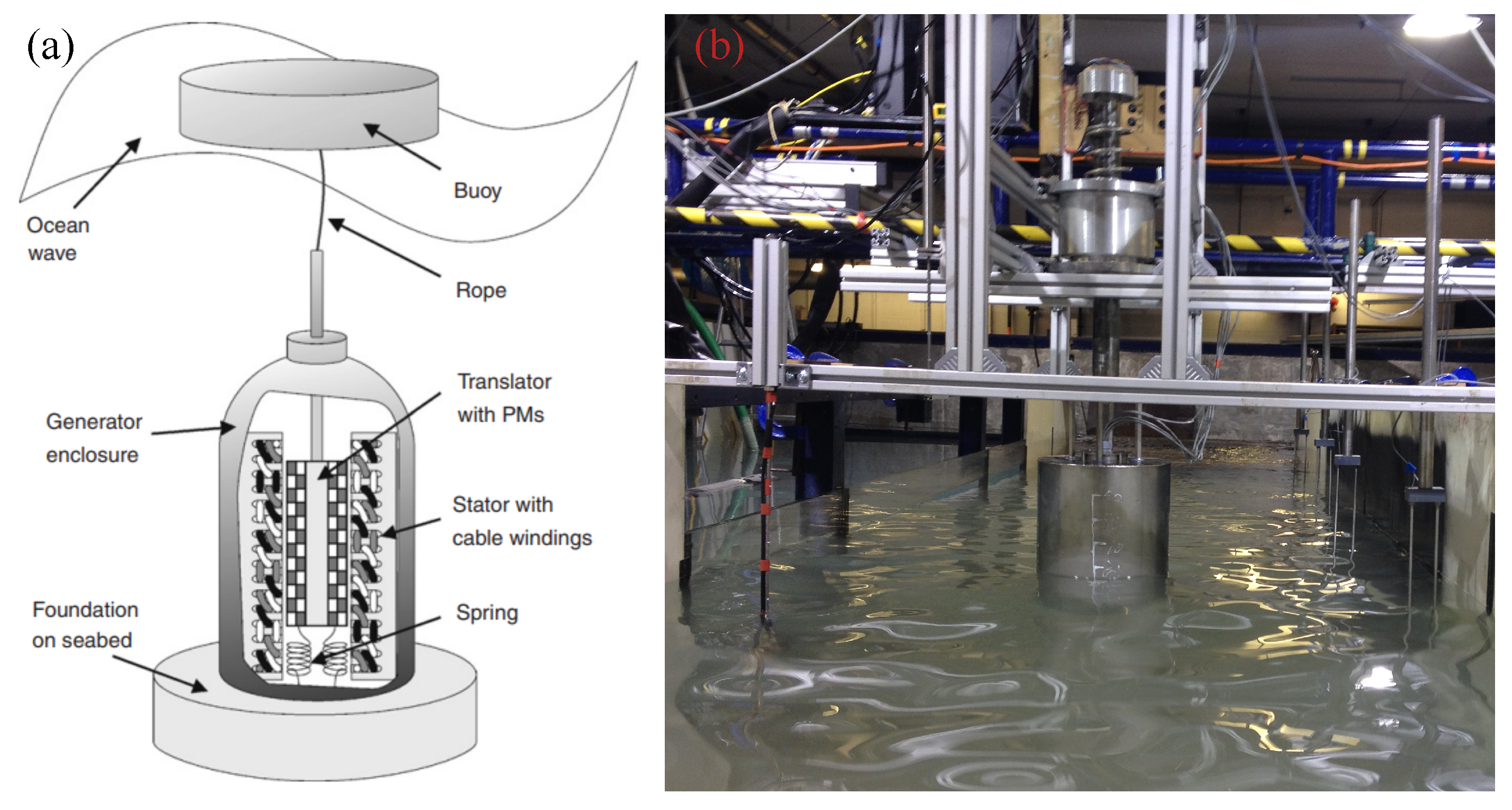
  80. Eriksson, M. Modelling and Experimental Verification of Direct Drive Wave Energy Conversion: Buoy-Generator Dynamics. Ph.D. Thesis, Uppsala University, Uppsala, Sweden, 2007. [Google Scholar]
  81. Rahm, M. Ocean Wave Energy: Underwater Substation System for Wave Energy Converters. Ph.D. Thesis, Uppsala University, Uppsala, Sweden, 2010. [Google Scholar]
  82. Waters, R.; Stålberg, M.; Danielsson, O.; Svensson, O.; Gustafsson, S.; Strömstedt, E.; Eriksson, M.; Sundberg, J.; Leijon, M. Experimental results from sea trials of an offshore wave energy system. Appl. Phys. Lett. 2007, 90, 034105. [Google Scholar] [CrossRef]
  83. Lejerskog, E.; Boström, C.; Hai, L.; Waters, R.; Leijon, M. Experimental results on power absorption from a wave energy converter at the Lysekil wave energy research site. Renew. Energy 2015, 77, 9–14. [Google Scholar] [CrossRef]
  84. Boström, C.; Lejerskog, E.; Tyrberg, S.; Svensson, O.; Waters, R.; Savin, A.; Bolund, B.; Eriksson, M.; Leijon, M. Experimental results from an offshore wave energy converter. J. Offshore Mech. Arct. Eng. 2010, 132, 041103. [Google Scholar] [CrossRef]
  85. Leijon, M.; Boström, C.; Danielsson, O.; Gustafsson, S.; Haikonen, K.; Langhamer, O.; Strömstedt, E.; Stålberg, M.; Sundberg, J.; Svensson, O.; et al. Wave energy from the North Sea: Experiences from the Lysekil research site. Surv. Geophys. 2008, 29, 221–240. [Google Scholar] [CrossRef] [Green Version]
  86. Sjolte, J.; Tjensvoll, G.; Molinas, M. Power collection from wave energy farms. Appl. Sci. 2013, 3, 420–436. [Google Scholar] [CrossRef]
  87. Sjolte, J.; Tjensvoll, G.; Molinas, M. Self-sustained all-electric wave energy converter system. COMPEL Int. J. Comput. Math. Electr. Electron. Eng. 2014, 33, 1705–1721. [Google Scholar] [CrossRef]
  88. Joslin, J.; Cotter, E.; Murphy, P.; Gibbs, P.; Cavagnaro, R.; Crisp, C.; Stewart, A.R.; Polagye, B.; Cross, P.S.; Hjetland, E.; et al. The wave-powered adaptable monitoring package: Hardware design, installation, and deployment. In Proceedings of the European Wave and Tidal Energy Conference, Naples, Italy, 1–6 September 2019; pp. 1–6. [Google Scholar]
  89. CorpowerOcean. Corpower Ocean. 2021. Available online: https://corpowerocean.com/ (accessed on 8 August 2021).
  90. Todalshaug, J.H.; Ásgeirsson, G.S.; Hjálmarsson, E.; Maillet, J.; Möller, P.; Pires, P.; Guérinel, M.; Lopes, M. Tank testing of an inherently phase-controlled wave energy converter. Int. J. Mar. Energy 2016, 15, 68–84. [Google Scholar] [CrossRef]
  91. Berenjkoob, M.N.; Ghiasi, M.; Soares, C.G. Influence of the shape of a buoy on the efficiency of its dual-motion wave energy conversion. Energy 2020, 214, 118998. [Google Scholar] [CrossRef]
  92. Jin, S.; Patton, R.J.; Guo, B. Enhancement of wave energy absorption efficiency via geometry and power take-off damping tuning. Energy 2019, 169, 819–832. [Google Scholar] [CrossRef]
  93. Polinder, H.; Damen, M.E.; Gardner, F.; de Sousa Prado, M.G. Archimedes wave swing linear permanent-magnet generator system performance. In Proceedings of the European Wave and Tidal Energy Conference, Glasgow, UK, 29 August–2 September 2005; pp. 383–387. [Google Scholar]
  94. de Sousa Prado, M.G.; Gardner, F.; Damen, M.; Polinder, H. Modelling and test results of the Archimedes wave swing. Proc. Inst. Mech. Eng. Part A J. Power Energy 2006, 220, 855–868. [Google Scholar] [CrossRef]
  95. Rafiee, A.; Fiévez, J. Numerical prediction of extreme loads on the CETO wave energy converter. In Proceedings of the European Wave and Tidal Energy Conference, Nantes, France, 6–11 September 2015; pp. 1–10. [Google Scholar]
  96. Valério, D.; Mendes, M.J.; Beirão, P.; da Costa, J.S. Identification and control of the AWS using neural network models. Appl. Ocean Res. 2008, 30, 178–188. [Google Scholar] [CrossRef]
  97. Curto, D.; Franzitta, V.; Guercio, A. Sea Wave Energy. A Review of the Current Technologies and Perspectives. Energies 2021, 14, 6604. [Google Scholar] [CrossRef]
  98. Prado, M.; Polinder, H. Direct drive in wave energy conversion–AWS full scale prototype case study. In Proceedings of the IEEE Power and Energy Society General Meeting, Detroit, MI, USA, 24–28 July 2011; pp. 1–7. [Google Scholar]
  99. Valerio, D.; Beirao, P.; Mendes, M.J.; da Costa, J.S. Comparison of control strategies performance for a wave energy converter. In Proceedings of the Mediterranean Conference on Control and Automation, Ajaccio, France, 25–27 June 2008; pp. 773–778. [Google Scholar]
  100. Gaudin, C.; David, D.; Cai, Y.; Hansen, J.; Bransby, M.; Rijnsdorp, D.; Lowe, R.; O’Loughlin, C.; Lu, T.; Uzielli, M.; et al. From Single to Multiple Wave Energy Converters: Cost Reduction through Location and Configuration Optimisation; Technical Report; The University of Western Australia: Perth, Australia, 2021. [Google Scholar]
  101. ARENA. How a Perth Company Created the World’s Most Advanced Wave Energy Device. 2017. Available online: https://arena.gov.au/blog/ceto-6/ (accessed on 10 July 2022).
  102. Sergiienko, N.; Rafiee, A.; Cazzolato, B.; Ding, B.; Arjomandi, M. Feasibility study of the three-tether axisymmetric wave energy converter. Ocean Eng. 2018, 150, 221–233. [Google Scholar] [CrossRef]
  103. Sergiienko, N.Y.; Cazzolato, B.S.; Ding, B.; Hardy, P.; Arjomandi, M. Performance comparison of the floating and fully submerged quasi-point absorber wave energy converters. Renew. Energy 2017, 108, 425–437. [Google Scholar] [CrossRef] [Green Version]
  104. OPT. Ocean Power Technologies. 2021. Available online: https://oceanpowertechnologies.com/ (accessed on 8 August 2022).
  105. Tarrant, K.R. Numerical Modelling of Parametric Resonance of a Heaving Point Absorber Wave Energy Converter. Ph.D. Thesis, Trinity College Dublin, Dublin, Ireland, 2015. [Google Scholar]
  106. Liu, Y.; Li, Y.; He, F.; Wang, H. Comparison study of tidal stream and wave energy technology development between China and some Western Countries. Renew. Sustain. Energy Rev. 2017, 76, 701–716. [Google Scholar] [CrossRef]
  107. Tarrant, K.; Meskell, C. Investigation on parametrically excited motions of point absorbers in regular waves. Ocean Eng. 2016, 111, 67–81. [Google Scholar] [CrossRef]
  108. Edwards, K.; Mekhiche, M. Ocean power technologies Powerbuoy: System-level design, development and validation methodology. In Proceedings of the 2nd Marine Energy Technology Symposium (METS), Seattle, WA, USA, 15–18 April 2014; pp. 1–9. [Google Scholar]
  109. Mackay, E.; Cruz, J.; Retzler, C.; Arnold, P.; Bannon, E.; Pascal, R. Validation of a new wave energy converter design tool with large scale single machine experiments. In Proceedings of the 1st Asian Wave and Tidal Conference Series, Jeju Island, Korea, 27–30 November 2012; pp. 1–12. [Google Scholar]
  110. Mackay, E.; Cruz, J.; Livingstone, M.; Arnold, P. Validation of a Time-Domain Modelling Tool for Wave Energy Converter Arrays. In Proceedings of the European Wave and Tidal Energy Conference, Aalborg, Denmark, 2–6 September 2013; pp. 1–8. [Google Scholar]
  111. Kazmierkowski, M.P.; Jasiński, M. Power electronics for renewable sea wave energy. In Proceedings of the 12th International Conference on Optimization of Electrical and Electronic Equipment, Brasov, Romania, 20–22 May 2010; pp. 4–9. [Google Scholar]
  112. Babarit, A.; Clément, A.; Ruer, J.; Tartivel, C. SEAREV: A fully integrated wave energy converter. In Proceedings of the Offshore Wind and other Marine Renewable Energies in Mediterranean and European Seas, Rome, Italy, 5–7 September 2006; pp. 1–11. [Google Scholar]
  113. Wello. The Future of Wave Energy. 2021. Available online: https://wello.eu/ (accessed on 8 August 2022).
  114. Cordonnier, J.; Gorintin, F.; De Cagny, A.; Clément, A.H.; Babarit, A. SEAREV: Case study of the development of a wave energy converter. Renew. Energy 2015, 80, 40–52. [Google Scholar] [CrossRef]
  115. Xu, S.; Wang, S.; Soares, C.G. Review of mooring design for floating wave energy converters. Renew. Sustain. Energy Rev. 2019, 111, 595–621. [Google Scholar] [CrossRef]
  116. Josset, C.; Babarit, A.; Clément, A. A wave-to-wire model of the SEAREV wave energy converter. Proc. Inst. Mech. Eng. Part M J. Eng. Marit. Environ. 2007, 221, 81–93. [Google Scholar] [CrossRef]
  117. Babarit, A.; Clement, A.H. Shape optimisation of the SEAREV wave energy converter. In Proceedings of the World Renewable Energy Conference, Florence, Italy, 19–25 August 2006; pp. 1–6. [Google Scholar]
  118. Durand, M.; Babarit, A.; Pettinotti, B.; Quillard, O.; Toularastel, J.; Clément, A. Experimental validation of the performances of the SEAREV wave energy converter with real time latching control. In Proceedings of the 7th European Wave and Tidal Energy Conference (EWTEC), Porto, Portugal, 11–13 September 2007; Volume 1113. [Google Scholar]
  119. Beharie, R.; Side, J. Acoustic Environmental Monitoring:–Wello Penguin Cooling System Noise Study; A Report Commissioned by Aquatera Limited; Technical Report; International Centre for Island Technology: Orkney, UK, 2012.
  120. Mattiazzo, G. State of the art and perspectives of wave energy in the Mediterranean sea: Backstage of ISWEC. Front. Energy Res. 2019, 7, 114. [Google Scholar] [CrossRef] [Green Version]
  121. AMOG. AMOG Wave Energy Converter. 2021. Available online: https://amog.consulting/ (accessed on 8 September 2022).
  122. Pozzi, N.; Bracco, G.; Passione, B.; Sirigu, S.A.; Mattiazzo, G. PeWEC: Experimental validation of wave to PTO numerical model. Ocean Eng. 2018, 167, 114–129. [Google Scholar] [CrossRef]
  123. Crowley, S.; Porter, R.; Taunton, D.; Wilson, P.A. Modelling of the WITT wave energy converter. Renew. Energy 2018, 115, 159–174. [Google Scholar] [CrossRef] [Green Version]
  124. Wu, J.; Qian, C.; Zheng, S.; Chen, N.; Xia, D.; Göteman, M. Investigation on the wave energy converter that reacts against an internal inverted pendulum. Energy 2022, 247, 123493. [Google Scholar] [CrossRef]
  125. Ambühl, S.; Kramer, M.; Sørensen, J.D. Reliability-based structural optimization of wave energy converters. Energies 2014, 7, 8178–8200. [Google Scholar] [CrossRef] [Green Version]
  126. Gao, Z.; Moan, T. Mooring system analysis of multiple wave energy converters in a farm configuration. In Proceedings of the European Wave and Tidal Energy Conference, Uppsala, Sweden, 7–10 September 2009; pp. 509–518. [Google Scholar]
  127. Kramer, M.; Marquis, L.; Frigaard, P. Performance evaluation of the wavestar prototype. In Proceedings of the European Wave and Tidal Energy Conference, Southampton, UK, 5–9 September 2011; pp. 1–8. [Google Scholar]
  128. Ma, Y.; Zhang, A.; Yang, L.; Li, H.; Zhai, Z.; Zhou, H. Motion simulation and performance analysis of two-body floating point absorber wave energy converter. Renew. Energy 2020, 157, 353–367. [Google Scholar] [CrossRef]
  129. Marquis, L.; Kramer, M.; Frigaard, P. First power production figures from the Wave Star Roshage wave energy converter. In Proceedings of the 3rd International Conference on Ocean Energy (ICOE-2010), Bilbao, Spain, 6 October 2010; pp. 1–5. [Google Scholar]
  130. Leirbukt, A.; Tubass, P. A Wave of Renewable Energy. 2006. Available online: https://library.e.abb.com/public/1e2fadd298a58d14c12571d900412482/29-31%203M646_ENG72dpi.pdf (accessed on 10 July 2022).
  131. Wendt, F.; Nielsen, K.; Yu, Y.H.; Bingham, H.; Eskilsson, C.; Kramer, M.; Babarit, A.; Bunnik, T.; Costello, R.; Crowley, S.; et al. Ocean energy systems wave energy modelling task: Modelling, verification and validation of wave energy converters. J. Mar. Sci. Eng. 2019, 7, 379. [Google Scholar] [CrossRef] [Green Version]
  132. Sheng, W.; Alcorn, R.; Lewis, T. Physical modelling of wave energy converters. Ocean Eng. 2014, 84, 29–36. [Google Scholar] [CrossRef]
  133. Folley, M. Numerical Modelling of Wave Energy Converters: State-of-the-Art Techniques for Single Devices and Arrays; Academic Press: Cambridge, MA, USA, 2016. [Google Scholar]
  134. Jin, S.; Patton, R.J.; Guo, B. Viscosity effect on a point absorber wave energy converter hydrodynamics validated by simulation and experiment. Renew. Energy 2018, 129, 500–512. [Google Scholar] [CrossRef]
  135. Tran, N.; Sergiienko, N.; Cazzolato, B.; Ghayesh, M.; Arjomandi, M. Design considerations for a three-tethered point absorber wave energy converter with nonlinear coupling between hydrodynamic modes. Ocean Eng. 2022, 254, 111351. [Google Scholar] [CrossRef]
  136. Dafnakis, P.; Bhalla, A.P.S.; Sirigu, S.A.; Bonfanti, M.; Bracco, G.; Mattiazzo, G. Comparison of wave–structure interaction dynamics of a submerged cylindrical point absorber with three degrees of freedom using potential flow and computational fluid dynamics models. Phys. Fluids 2020, 32, 093307. [Google Scholar] [CrossRef]
  137. Rusch, C.J.; Mundon, T.R.; Maurer, B.D.; Polagye, B.L. Hydrodynamics of an asymmetric heave plate for a point absorber wave energy converter. Ocean Eng. 2020, 215, 107915. [Google Scholar] [CrossRef]
  138. Xu, Q.; Li, Y.; Yu, Y.H.; Ding, B.; Jiang, Z.; Lin, Z.; Cazzolato, B. Experimental and numerical investigations of a two-body floating-point absorber wave energy converter in regular waves. J. Fluids Struct. 2019, 91, 102613. [Google Scholar] [CrossRef]
  139. Katsidoniotaki, E.; Göteman, M. Numerical modeling of extreme wave interaction with point-absorber using OpenFOAM. Ocean Eng. 2022, 245, 110268. [Google Scholar] [CrossRef]
  140. DualSPHysics. DualSPHysics. Available online: https://dual.sphysics.org/ (accessed on 10 September 2020).
  141. Ropero-Giralda, P.; Crespo, A.J.; Tagliafierro, B.; Altomare, C.; Domínguez, J.M.; Gómez-Gesteira, M.; Viccione, G. Efficiency and survivability analysis of a point-absorber wave energy converter using DualSPHysics. Renew. Energy 2020, 162, 1763–1776. [Google Scholar] [CrossRef]
  142. Tagliafierro, B.; Martínez-Estévez, I.; Domínguez, J.M.; Crespo, A.J.; Göteman, M.; Engström, J.; Gómez-Gesteira, M. A numerical study of a taut-moored point-absorber wave energy converter with a linear power take-off system under extreme wave conditions. Appl. Energy 2022, 311, 118629. [Google Scholar] [CrossRef]
  143. Falnes, J. Ocean Waves and Oscillating Systems: Linear Interactions including Wave-Energy Extraction; Cambridge University Press: Cambridge, UK, 2002. [Google Scholar]
  144. Li, A.; Liu, Y. New analytical solutions to water wave diffraction by vertical truncated cylinders. Int. J. Nav. Archit. Ocean Eng. 2019, 11, 952–969. [Google Scholar] [CrossRef]
  145. Li, A.j.; Liu, Y.; Li, H.j. New analytical solutions to water wave radiation by vertical truncated cylinders through multi-term Galerkin method. Meccanica 2019, 54, 429–450. [Google Scholar] [CrossRef]
  146. Penalba Retes, M.; Mérigaud, A.; Gilloteaux, J.C.; Ringwood, J. Nonlinear Froude-Krylov force modelling for two heaving wave energy point absorbers. In Proceedings of the European Wave and Tidal Energy Conference, Nantes, France, 6–11 September 2015; pp. 1–10. [Google Scholar]
  147. Giorgi, G.; Ringwood, J.V. Nonlinear Froude-Krylov and viscous drag representations for wave energy converters in the computation/fidelity continuum. Ocean Eng. 2017, 141, 164–175. [Google Scholar] [CrossRef] [Green Version]
  148. Cummins, W. The Impulse Response Function and Ship Motions; Technical Report; David Taylor Model Basin: Washington, DC, USA, 1962. [Google Scholar]
  149. Giorgi, G.; Ringwood, J.V. Computationally efficient nonlinear Froude–Krylov force calculations for heaving axisymmetric wave energy point absorbers. J. Ocean Eng. Mar. Energy 2017, 3, 21–33. [Google Scholar] [CrossRef]
  150. Giorgi, G.; Ringwood, J.V. Analytical representation of nonlinear Froude-Krylov forces for 3-DoF point absorbing wave energy devices. Ocean Eng. 2018, 164, 749–759. [Google Scholar] [CrossRef] [Green Version]
  151. Merigaud, A.; Gilloteaux, J.C.; Ringwood, J.V. A nonlinear extension for linear boundary element methods in wave energy device modelling. In Proceedings of the International Conference on Offshore Mechanics and Arctic Engineering, Rio de Janeiro, Brazil, 1–6 July 2012; pp. 1–7. [Google Scholar]
  152. Morison, J.R.; Johnson, J.W.; Schaaf, S.A. The force exerted by surface waves on piles. J. Pet. Technol. 1950, 2, 149–154. [Google Scholar] [CrossRef]
  153. Guo, B.; Patton, R.; Jin, S.; Gilbert, J.; Parsons, D. Nonlinear modeling and verification of a heaving point absorber for wave energy conversion. IEEE Trans. Sustain. Energy 2017, 9, 453–461. [Google Scholar] [CrossRef]
  154. Gudmestad, O.T.; Moe, G. Hydrodynamic coefficients for calculation of hydrodynamic loads on offshore truss structures. Mar. Struct. 1996, 9, 745–758. [Google Scholar] [CrossRef]
  155. Giorgi, G.; Ringwood, J. Consistency of viscous drag identification tests for wave energy applications. In Proceedings of the European Wave and Tidal Energy Conference, Cork, Ireland, 27 August–1 September 2017; pp. 1–8. [Google Scholar]
  156. Wang, H.; Sitanggang, K.; Falzarano, J. Exploration of power take off in wave energy converters with two-body interaction. Ocean Syst. Eng. 2017, 7, 89–106. [Google Scholar]
  157. Ji, X.; Al Shami, E.; Monty, J.; Wang, X. Modelling of linear and non-linear two-body wave energy converters under regular and irregular wave conditions. Renew. Energ. 2020, 147, 487–501. [Google Scholar] [CrossRef]
  158. Flocard, F.; Finnigan, T.D. Increasing power capture of a wave energy device by inertia adjustment. Appl. Ocean Res. 2012, 34, 126–134. [Google Scholar] [CrossRef]
  159. Davidson, J.; Giorgi, S.; Ringwood, J.V. Identification of wave energy device models from numerical wave tank data—Part 1: Numerical wave tank identification tests. IEEE Trans. Sustain. Energy 2016, 7, 1012–1019. [Google Scholar] [CrossRef] [Green Version]
  160. Giorgi, S.; Davidson, J.; Ringwood, J.V. Identification of wave energy device models from numerical wave tank data—Part 2: Data-based model determination. IEEE Trans. Sustain. Energy 2016, 7, 1020–1027. [Google Scholar] [CrossRef] [Green Version]
  161. Bacelli, G.; Coe, R.G.; Patterson, D.; Wilson, D. System identification of a heaving point absorber: Design of experiment and device modeling. Energies 2017, 10, 472. [Google Scholar] [CrossRef] [Green Version]
  162. Giorgi, S.; Davidson, J.; Jakobsen, M.; Kramer, M.; Ringwood, J.V. Identification of dynamic models for a wave energy converter from experimental data. Ocean Eng. 2019, 183, 426–436. [Google Scholar] [CrossRef]
  163. Guo, W.; Zhou, Y.H.; Zhang, W.C.; Zhao, Q.S. Hydrodynamic analysis and power conversion for point absorber WEC with two degrees of freedom using CFD. China Ocean Eng. 2018, 32, 718–729. [Google Scholar] [CrossRef]
  164. Guo, B.; Patton, R.J. Non-linear viscous and friction effects on a heaving point absorber dynamics and latching control performance. In Proceedings of the IFAC World Congress, Toulouse, France, 27 August–1 September 2017; pp. 15657–15662. [Google Scholar]
  165. Jin, S.; Guo, B.; Patton, R.; Gilbert, J.; Abdelrahman, M. Non-linear analysis of a point absorber wave energy converter. In Proceedings of the International Conference on Offshore Renewable Energy, Glasgow, Scotland, 12–14 September 2016; pp. 1–6. [Google Scholar]
  166. Jusoh, M.A.; Ibrahim, M.Z.; Daud, M.Z.; Albani, A.; Mohd Yusop, Z. Hydraulic power take-off concepts for wave energy conversion system: A review. Energies 2019, 12, 4510. [Google Scholar] [CrossRef] [Green Version]
  167. Têtu, A.; Ferri, F.; Kramer, M.B.; Hals Todalshaug, J. Physical and mathematical modeling of a wave energy converter equipped with a negative spring mechanism for phase control. Energies 2018, 11, 2362. [Google Scholar] [CrossRef] [Green Version]
  168. Zhang, D.; Li, W.; Lin, Y.; Bao, J. An overview of hydraulic systems in wave energy application in China. Renew. Sustain. Energy Rev. 2012, 16, 4522–4526. [Google Scholar] [CrossRef]
  169. Liu, C. Current Research Status and Challenge for Direct-Drive Wave Energy Conversions. IETE J. Res. 2021, 1, 1–13. [Google Scholar] [CrossRef]
  170. Penalba, M.; Sell, N.P.; Hillis, A.J.; Ringwood, J.V. Validating a wave-to-wire model for a wave energy converte–Part I: The Hydraulic Transmission System. Energies 2017, 10, 977. [Google Scholar] [CrossRef] [Green Version]
  171. Penalba, M.; Cortajarena, J.A.; Ringwood, J.V. Validating a wave-to-wire model for a wave energy converter–Part II: The electrical system. Energies 2017, 10, 1002. [Google Scholar] [CrossRef] [Green Version]
  172. Vantorre, M.; Banasiak, R.; Verhoeven, R. Modelling of hydraulic performance and wave energy extraction by a point absorber in heave. Appl. Ocean Res. 2004, 26, 61–72. [Google Scholar] [CrossRef]
  173. Kim, S.J.; Koo, W.; Shin, M.J. Numerical and experimental study on a hemispheric point-absorber-type wave energy converter with a hydraulic power take-off system. Renew. Energy 2019, 135, 1260–1269. [Google Scholar] [CrossRef]
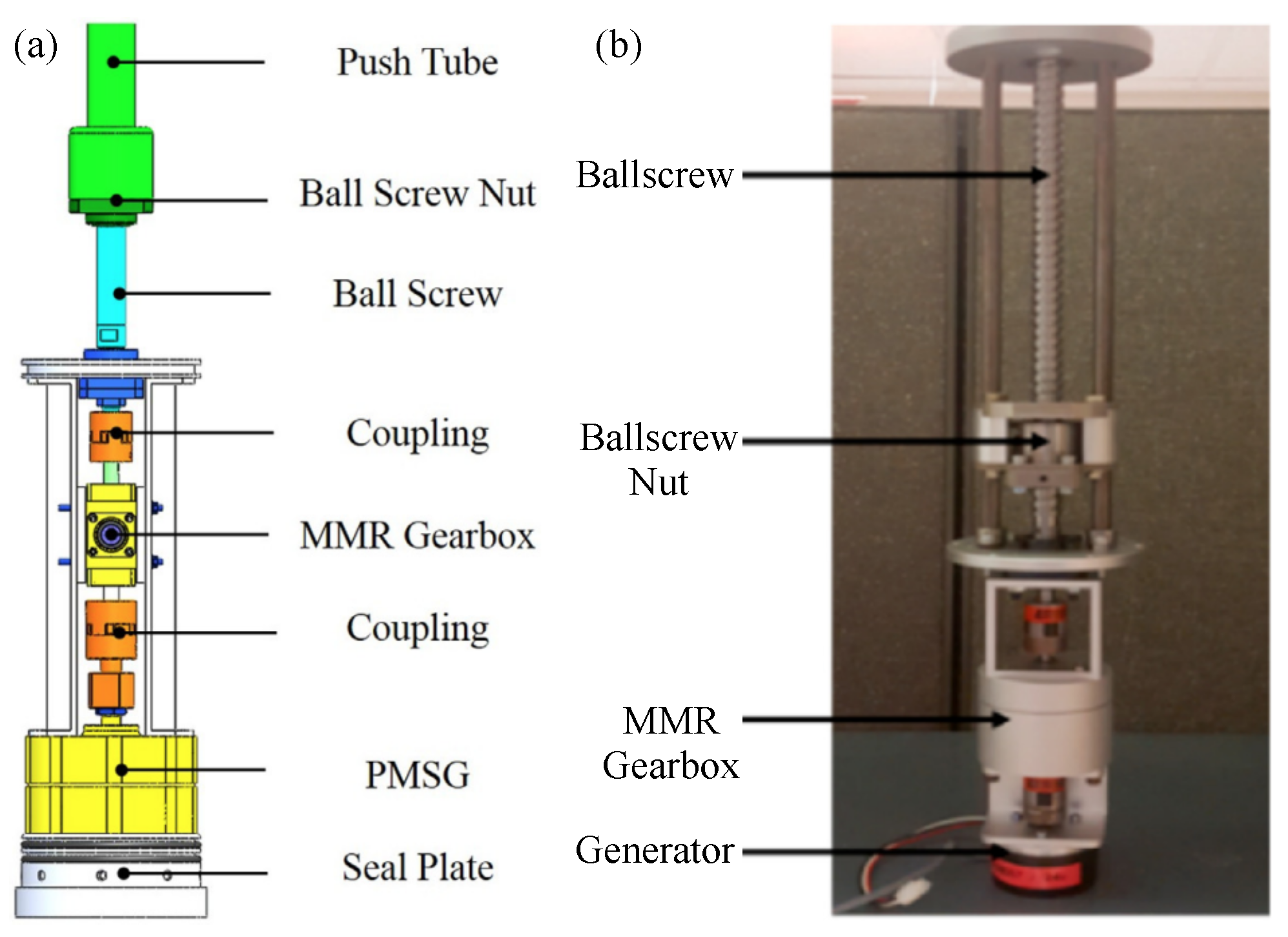
  174. Li, X.; Chen, C.; Li, Q.; Xu, L.; Liang, C.; Ngo, K.; Parker, R.G.; Zuo, L. A compact mechanical power take-off for wave energy converters: Design, analysis, and test verification. Appl. Energy 2020, 278, 115459. [Google Scholar] [CrossRef]
  175. Liang, C.; Ai, J.; Zuo, L. Design, fabrication, simulation and testing of an ocean wave energy converter with mechanical motion rectifier. Ocean Eng. 2017, 136, 190–200. [Google Scholar] [CrossRef]
  176. Mueller, M.; Baker, N. Direct drive electrical power take-off for offshore marine energy converters. Proc. Inst. Mech. Eng. Part A J. Power Energy 2005, 219, 223–234. [Google Scholar] [CrossRef]
  177. Rhinefrank, K.; Schacher, A.; Prudell, J.; Brekken, T.K.; Stillinger, C.; Yen, J.Z.; Ernst, S.G.; von Jouanne, A.; Amon, E.; Paasch, R.; et al. Comparison of direct-drive power takeoff systems for ocean wave energy applications. IEEE J. Ocean Eng. 2011, 37, 35–44. [Google Scholar] [CrossRef]
  178. Faiz, J.; Nematsaberi, A. Linear electrical generator topologies for direct-drive marine wave energy conversion-an overview. IET Renew. Power Gener. 2017, 11, 1163–1176. [Google Scholar] [CrossRef]
  179. Liu, W.; Xu, L.; Bu, T.; Yang, H.; Liu, G.; Li, W.; Pang, Y.; Hu, C.; Zhang, C.; Cheng, T. Torus structured triboelectric nanogenerator array for water wave energy harvesting. Nano Energy 2019, 58, 499–507. [Google Scholar] [CrossRef]
  180. Collins, I.; Hossain, M.; Dettmer, W.; Masters, I. Flexible membrane structures for wave energy harvesting: A review of the developments, materials and computational modelling approaches. Renew. Sustain. Energy Rev. 2021, 151, 111478. [Google Scholar] [CrossRef]
  181. Wu, S.; Liu, Y.; Qin, J. Experimental analyses of two-body wave energy converters with hydraulic power take-off damping in regular and irregular waves. IET Renew. Power Gener. 2021, 15, 3165–3175. [Google Scholar] [CrossRef]
  182. Polinder, H.; Mecrow, B.C.; Jack, A.G.; Dickinson, P.G.; Mueller, M.A. Conventional and TFPM linear generators for direct-drive wave energy conversion. IEEE Trans. Energy Convers. 2005, 20, 260–267. [Google Scholar] [CrossRef] [Green Version]
  183. Cargo, C.; Hillis, A.; Plummer, A. Strategies for active tuning of Wave Energy Converter hydraulic power take-off mechanisms. Renew. Energy 2016, 94, 32–47. [Google Scholar] [CrossRef] [Green Version]
  184. Henderson, R. Design, simulation, and testing of a novel hydraulic power take-off system for the Pelamis wave energy converter. Renew. Energy 2006, 31, 271–283. [Google Scholar] [CrossRef]
  185. António, F.d.O. Phase control through load control of oscillating-body wave energy converters with hydraulic PTO system. Ocean Eng. 2008, 35, 358–366. [Google Scholar]
  186. Li, X.; Martin, D.; Liang, C.; Chen, C.; Parker, R.G.; Zuo, L. Characterization and verification of a two-body wave energy converter with a novel power take-off. Renew. Energy 2021, 163, 910–920. [Google Scholar] [CrossRef]
  187. Omholt, T. A wave activated electric generator. In Proceedings of the OCEANS, Washington, DC, USA, 6–8 September 1978; pp. 585–589. [Google Scholar]
  188. Mueller, M.; Baker, N.; Ran, L.; Chong, N.; Wei, H.; Tavner, P.; McKeever, P. Experimental tests of an air-cored PM tubular generator for direct drive wave energy converters. In Proceedings of the IET Conference on Power Electronics, Machines and Drives, York, UK, 2–4 April 2008; pp. 747–751. [Google Scholar]
  189. Hodgins, N.; Keysan, O.; McDonald, A.S.; Mueller, M.A. Design and testing of a linear generator for wave-energy applications. IEEE Trans. Ind. Electron. 2012, 59, 2094–2103. [Google Scholar] [CrossRef]
  190. Mueller, M.; Baker, N. A low speed reciprocating permanent magnet generator for direct drive wave energy converters. In Proceedings of the International Conference on Power Electronics Machines and Drives, Bath, UK, 16–18 April 2002; pp. 468–473. [Google Scholar]
  191. Mueller, M.; Polinder, H.; Baker, N. Current and novel electrical generator technology for wave energy converters. In Proceedings of the IEEE International Conference on Electric Machines and Drives (IEMDC), Antalya, Turkey, 3–5 May 2007; Volume 2, pp. 1401–1406. [Google Scholar]
  192. Khatri, P.; Wang, X. Comprehensive review of a linear electrical generator for ocean wave energy conversion. IET Renew. Power Gener. 2020, 14, 949–958. [Google Scholar] [CrossRef]
  193. Rhinefrank, K.; Prudell, J.; Schacher, A. Development and characterization of a novel direct drive rotary wave energy point absorber. In Proceedings of the OCEANS 2009, Biloxi, MS, USA, 26–29 October 2009; pp. 1–5. [Google Scholar]
  194. Thorburn, K.; Leijon, M. Farm size comparison with analytical model of linear generator wave energy converters. Ocean Eng. 2007, 34, 908–916. [Google Scholar] [CrossRef]
  195. Leijon, M.; Danielsson, O.; Eriksson, M.; Thorburn, K.; Bernhoff, H.; Isberg, J.; Sundberg, J.; Ivanova, I.; Sjöstedt, E.; Ågren, O.; et al. An electrical approach to wave energy conversion. Renew. Energy 2006, 31, 1309–1319. [Google Scholar] [CrossRef]
  196. Genest, R.; Bonnefoy, F.; Clément, A.H.; Babarit, A. Effect of non-ideal power take-off on the energy absorption of a reactively controlled one degree of freedom wave energy converter. Appl. Ocean Res. 2014, 48, 236–243. [Google Scholar] [CrossRef] [Green Version]
  197. Sjolte, J.; Bjerke, I.; Crozier, A.; Tjensvoll, G.; Molinas, M. All-electric wave energy power take off system with improved power quality at the grid connection point. In Proceedings of the Transmission and Distribution Conference and Exposition (T&D), 2012 IEEE PES, Orlando, FL, USA, 7–10 May 2012; pp. 1–7. [Google Scholar]
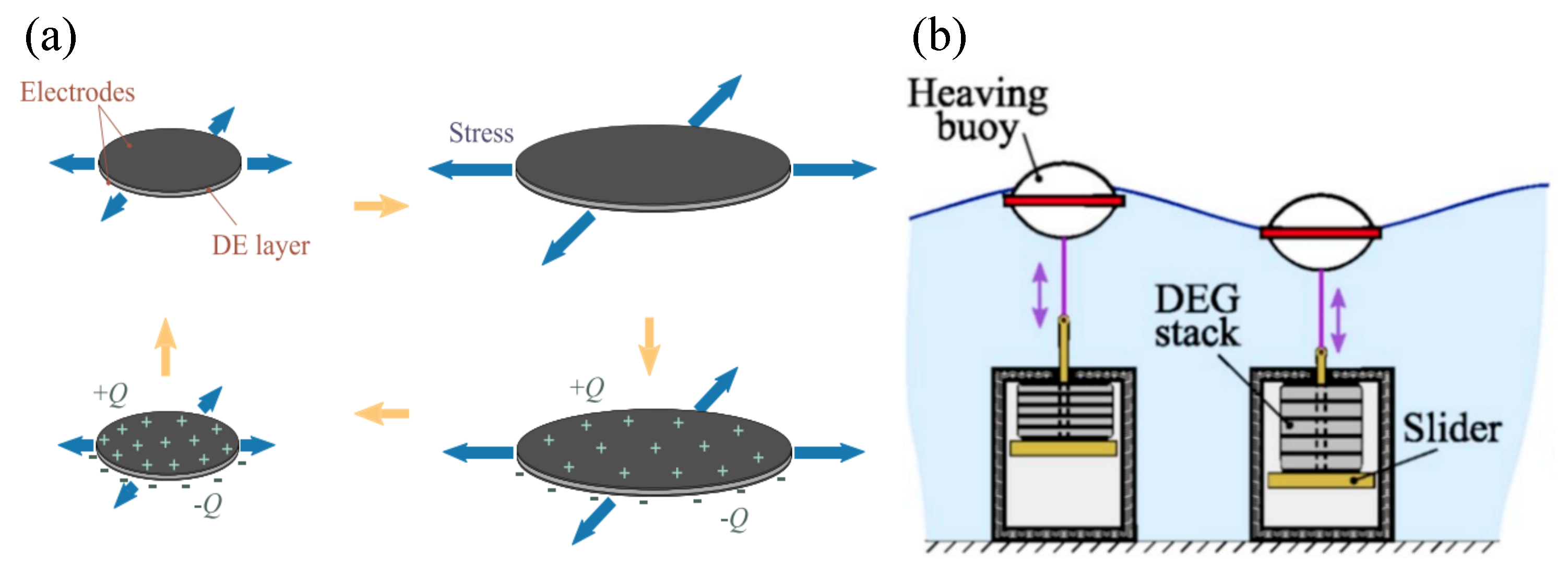
  198. Moretti, G.; Herran, M.S.; Forehand, D.; Alves, M.; Jeffrey, H.; Vertechy, R.; Fontana, M. Advances in the development of dielectric elastomer generators for wave energy conversion. Renew. Sustain. Energy Rev. 2020, 117, 109430. [Google Scholar] [CrossRef]
  199. Di, K.; Bao, K.; Chen, H.; Xie, X.; Tan, J.; Shao, Y.; Li, Y.; Xia, W.; Xu, Z.; E, S. Dielectric elastomer generator for electromechanical energy conversion: A mini review. Sustainability 2021, 13, 9881. [Google Scholar] [CrossRef]
  200. Pelrine, R.; Kornbluh, R.; Pei, Q.; Joseph, J. High-speed electrically actuated elastomers with strain greater than 100%. Science 2000, 287, 836–839. [Google Scholar] [CrossRef] [PubMed]
  201. Chiba, S.; Waki, M.; Masuda, K.; Ikoma, T. Current status and future prospects of electric generators using electroactive polymer artificial muscle. In Proceedings of the OCEANS, Sydney, NSW, Australia, 24–27 May 2010; pp. 1–5. [Google Scholar]
  202. Papini, G.P.R.; Vertechy, R.; Fontana, M. Dynamic model of dielectric elastomer diaphragm generators for oscillating water column wave energy converters. In Proceedings of the ASME 2013 Conference on Smart Materials, Adaptive Structures and Intelligent Systems, Snowbird, UT, USA, 16–18 September 2013; pp. 1–9. [Google Scholar]
  203. Vertechy, R.; Fontana, M.; Papini, G.R.; Bergamasco, M. Oscillating-water-column wave-energy-converter based on dielectric elastomer generator. In Proceedings of the SPIE Smart Structures and Materials+ Nondestructive Evaluation and Health Monitoring, San Diego, CA, USA, 10–14 March 2013; p. 86870I. [Google Scholar]
  204. Fusco, F.; Ringwood, J.V. A simple and effective real-time controller for wave energy converters. IEEE Trans. Sustain. Energy 2012, 4, 21–30. [Google Scholar] [CrossRef]
  205. Davidson, J.; Genest, R.; Ringwood, J.V. Adaptive control of a wave energy converter. IEEE Trans. Sustain. Energy 2018, 9, 1588–1595. [Google Scholar] [CrossRef] [Green Version]
  206. Babarit, A.; Guglielmi, M.; Clément, A.H. Declutching control of a wave energy converter. Ocean Eng. 2009, 36, 1015–1024. [Google Scholar] [CrossRef] [Green Version]
  207. Guo, B.; Patton, R.J.; Jin, S.; Lan, J. Numerical and experimental studies of excitation force approximation for wave energy conversion. Renew. Energy 2018, 125, 877–889. [Google Scholar] [CrossRef]
  208. Guo, B.; Patton, R.; Jin, S. Identification and validation of excitation force for a heaving point absorber wave energy convertor. In Proceedings of the European Wave and Tidal Energy Conference, Cork, Ireland, 27 August–1 September 2017; pp. 1–9. [Google Scholar]
  209. Abdelrahman, M.; Patton, R.; Guo, B.; Lan, J. Estimation of wave excitation force for wave energy converters. In Proceedings of the 2016 3rd Conference on Control and Fault-Tolerant Systems (SysTol), Barcelona, Spain, 7–9 September 2016; pp. 654–659. [Google Scholar]
  210. Garcia-Abril, M.; Paparella, F.; Ringwood, J.V. Excitation force estimation and forecasting for wave energy applications. In Proceedings of the IFAC World Congress, Toulouse, France, 9–14 July 2017; pp. 14692–14697. [Google Scholar]
  211. Peña-Sanchez, Y.; Windt, C.; Davidson, J.; Ringwood, J.V. A critical comparison of excitation force estimators for wave-energy devices. IEEE Trans. Control Syst. Technol. 2019, 28, 2263–2275. [Google Scholar] [CrossRef]
  212. French, M.J.; Bracewell, R. Ps Frog: A Point-Absorber Wave Energy Converter Working in a Pitch/Surge Mode. In Proceedings of the International Conference on Energy Options: The Role of Alternatives in the World Energy Scene, Reading, UK, 7–9 April 1987; pp. 198–200. [Google Scholar]
  213. Giassi, M.; Thomas, S.; Tosdevin, T.; Engström, J.; Hann, M.; Isberg, J.; Göteman, M. Capturing the experimental behaviour of a point-absorber WEC by simplified numerical models. J. Fluids Struct. 2020, 99, 103143. [Google Scholar] [CrossRef]
  214. Guo, B.; Ringwood, J. On energy transfer of parametric resonance for wave energy conversion. In Proceedings of the European Wave and Tidal Energy Conference, Plymouth, UK, 5–9 September 2021; pp. 1–10. [Google Scholar]
  215. Hollm, M.; Dostal, L.; Yurchenko, D.; Seifried, R. Performance increase of wave energy harvesting of a guided point absorber. Eur. Phys. J. Spec. Top. 2022, 231, 1465–1473. [Google Scholar] [CrossRef]
  216. López, M.; Taveira-Pinto, F.; Rosa-Santos, P. Numerical modelling of the CECO wave energy converter. Renew. Energy 2017, 113, 202–210. [Google Scholar] [CrossRef]
  217. López, M.; Ramos, V.; Rosa-Santos, P.; Taveira-Pinto, F. Effects of the PTO inclination on the performance of the CECO wave energy converter. Mar. Struct. 2018, 61, 452–466. [Google Scholar] [CrossRef]
  218. Rosa-Santos, P.; Taveira-Pinto, F.; Rodríguez, C.A.; Ramos, V.; López, M. The CECO wave energy converter: Recent developments. Renew. Energy 2019, 139, 368–384. [Google Scholar] [CrossRef]
  219. Ramos, V.; López, M.; Taveira-Pinto, F.; Rosa-Santos, P. Performance assessment of the CECO wave energy converter: Water depth influence. Renew. Energy 2018, 117, 341–356. [Google Scholar] [CrossRef]
  220. Rodríguez, C.A.; Rosa-Santos, P.; Taveira-Pinto, F. Hydrodynamic optimization of the geometry of a sloped-motion wave energy converter. Ocean Eng. 2020, 199, 107046. [Google Scholar] [CrossRef]
  221. Giannini, G.; López, M.; Ramos, V.; Rodríguez, C.A.; Rosa-Santos, P.; Taveira-Pinto, F. Geometry assessment of a sloped type wave energy converter. Renew. Energy 2021, 171, 672–686. [Google Scholar] [CrossRef]
  222. Rodríguez, C.A.; Rosa-Santos, P.; Taveira-Pinto, F. Assessment of damping coefficients of power take-off systems of wave energy converters: A hybrid approach. Energy 2019, 169, 1022–1038. [Google Scholar] [CrossRef]
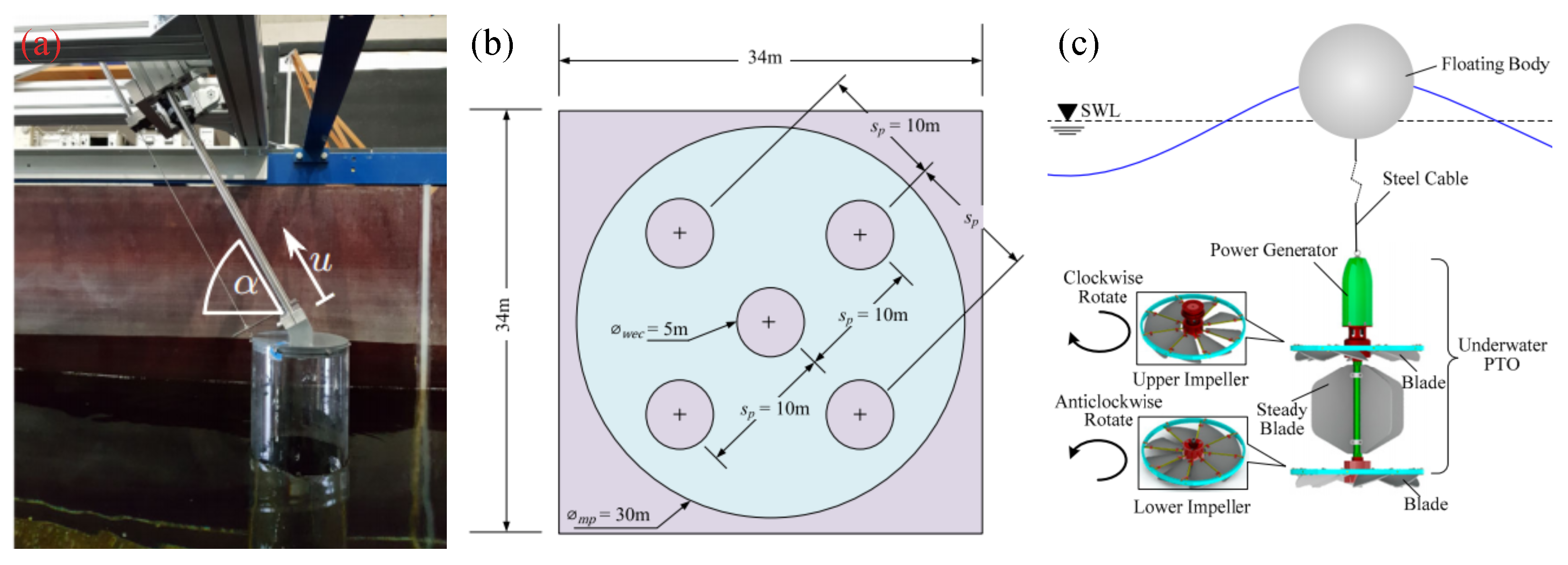
  223. Tay, Z.Y. Energy generation enhancement of arrays of point absorber wave energy converters via Moonpool’s resonance effect. Renew. Energy 2022, 188, 830–848. [Google Scholar] [CrossRef]
  224. Cong, D.; Shang, J.; Luo, Z.; Sun, C.; Wu, W. Energy efficiency analysis of multi-type floating bodies for a novel heaving point absorber with application to low-power unmanned ocean device. Energies 2018, 11, 3282. [Google Scholar] [CrossRef] [Green Version]
  225. Tay, Z.Y. Effect of resonance and wave reflection in semi-enclosed moonpool on performance enhancement of point absorber arrays. Ocean Eng. 2022, 243, 110182. [Google Scholar] [CrossRef]
  226. Guo, B.; Elmoosa, Q.; Windt, C.; Ringwood, J. Impact of nonlinear hydrodynamic modelling on geometric optimisation of a spherical heaving point absorber. In Proceedings of the European Wave and Tidal Energy Conference, Plymouth, UK, 5–9 September 2021; pp. 1–10. [Google Scholar]
  227. Shahroozi, Z.; Göteman, M.; Engström, J. Experimental investigation of a point-absorber wave energy converter response in different wave-type representations of extreme sea states. Ocean Eng. 2022, 248, 110693. [Google Scholar] [CrossRef]
  228. Xu, S.; Wang, S.; Soares, C.G. Experimental study of the influence of the rope material on mooring fatigue damage and point absorber response. Ocean Eng. 2021, 232, 108667. [Google Scholar] [CrossRef]
  229. Guo, B.; Ringwood, J.V. Modelling of a vibro-impact power take-off mechanism for wave energy conversion. In Proceedings of the European Control Conference, St. Petersburg, Russia, 12–15 May 2020; pp. 1348–1353. [Google Scholar]
  230. Guo, B.; Ringwood, J.V. Non-Linear Modelling of a Vibro-Impact Wave Energy Converter. IEEE Trans. Sustain. Energy 2021, 12, 492–500. [Google Scholar] [CrossRef]
  231. Guo, B.; Ringwood, J.V. Parametric study of a vibro-impact wave energy converter. In Proceedings of the IFAC World Congress, Berlin, Germany, 11–17 July 2020; pp. 12283–12288. [Google Scholar]
  232. Chen, M.; Xiao, P.; Zhang, Z.; Sun, L.; Li, F. Effects of the end-stop mechanism on the nonlinear dynamics and power generation of a point absorber in regular waves. Ocean Eng. 2021, 242, 110123. [Google Scholar] [CrossRef]
  233. Zou, S.; Abdelkhalik, O.; Robinett, R.; Korde, U.; Bacelli, G.; Wilson, D.; Coe, R. Model Predictive Control of parametric excited pitch-surge modes in wave energy converters. Int. J. Mar. Energy 2017, 19, 32–46. [Google Scholar] [CrossRef] [Green Version]
  234. Davidson, J.; Kalmár-Nagy, T. A Real-Time Detection System for the Onset of Parametric Resonance in Wave Energy Converters. J. Mar. Sci. Eng. 2020, 8, 819. [Google Scholar] [CrossRef]
  235. Palm, J.; Eskilsson, C.; Bergdahl, L. Parametric Excitation of Moored Wave Energy Converters Using Viscous and Non-Viscous CFD Simulations; Taylor & Francis Group: Abingdon, UK, 2018. [Google Scholar]
  236. Kovacic, I.; Rand, R.; Mohamed Sah, S. Mathieu’s equation and its generalizations: Overview of stability charts and their features. Appl. Mech. Rev. 2018, 70, 020802. [Google Scholar] [CrossRef] [Green Version]
  237. Iseki, T.; Xu, P. Experimental Study on Coupled Motions of a Spar-Buoy Under Mathieu Instability. In Proceedings of the International Conference on Offshore Mechanics and Arctic Engineering, Glasgow, UK, 9–14 June 2019; Volume 58899, p. V010T09A027. [Google Scholar]
  238. Giorgi, G.; Gomes, R.P.; Bracco, G.; Mattiazzo, G. Numerical investigation of parametric resonance due to hydrodynamic coupling in a realistic wave energy converter. Nonlinear Dyn. 2020, 101, 153–170. [Google Scholar] [CrossRef]
  239. Giorgi, G.; Gomes, R.P.; Bracco, G.; Mattiazzo, G. The effect of mooring line parameters in inducing parametric resonance on the spar-buoy oscillating water column wave energy converter. J. Mar. Sci. Eng. 2020, 8, 29. [Google Scholar] [CrossRef] [Green Version]
  240. Yang, H.; Xu, P. Effect of hull geometry on parametric resonances of spar in irregular waves. Ocean Eng. 2015, 99, 14–22. [Google Scholar] [CrossRef]
  241. Haslum, H. Simplified Methods Applied to Nonlinear Motion of Spar Platforms. Ph.D. Thesis, Norwegian University of Science and Technology, Trondheim, Norway, 2000. [Google Scholar]
  242. Giorgi, G.; Ringwood, J.V. Articulating parametric resonance for an OWC spar buoy in regular and irregular waves. J. Ocean. Eng. Mar. Energy 2018, 4, 311–322. [Google Scholar] [CrossRef]
  243. Rafiee, A.; Wolgamot, H.; Draper, S. Identifying the design wave group for the extreme response of a point absorber wave energy converter. In Proceedings of the Asian Wave and Tidal Energy Conference, Marina Bay Sands, Singapore, 24–28 October 2016; pp. 1–8. [Google Scholar]
  244. Ransley, E.; Greaves, D.; Raby, A.; Simmonds, D.; Jakobsen, M.M.; Kramer, M. RANS-VOF modelling of the wavestar point absorber. Renew. Energy 2017, 109, 49–65. [Google Scholar] [CrossRef] [Green Version]
  245. Ransley, E.; Greaves, D.; Raby, A.; Simmonds, D.; Hann, M. Survivability of wave energy converters using CFD. Renew. Energy 2017, 109, 235–247. [Google Scholar] [CrossRef] [Green Version]
  246. Chen, W.; Dolguntseva, I.; Savin, A.; Zhang, Y.; Li, W.; Svensson, O.; Leijon, M. Numerical modelling of a point-absorbing wave energy converter in irregular and extreme waves. Appl. Ocean Res. 2017, 63, 90–105. [Google Scholar] [CrossRef]
  247. Bretl, J.; Parsa, K.; Edwards, K.; Montgomery, J.; Mekhiche, M. The deployment of the PB-3-50-A1 PowerBuoy: Power prediction and measurement comparison. In Proceedings of the Marine Energy Technology Symposium METS, Washington, DC, USA, 25–27 April 2016; pp. 1–4. [Google Scholar]
  248. Balitsky, P.; Bacelli, G.; Ringwood, J.V. Control-influenced layout optimization of arrays of wave energy converters. In Proceedings of the International Conference on Ocean, Offshore and Artic Engineering, San Francisco, CA, USA, 8–13 June 2014; pp. 1–10. [Google Scholar]
  249. Child, B.F.M. On the Configuration of Arrays of Floating Wave Energy Converters. Ph.D. Thesis, University of Edinburgh, Edinburgh, UK, 2011. [Google Scholar]
  250. Fang, H.W.; Feng, Y.Z.; Li, G.P. Optimization of wave energy converter arrays by an improved differential evolution algorithm. Energies 2018, 11, 3522. [Google Scholar] [CrossRef] [Green Version]
  251. Garcia-Rosa, P.B.; Bacelli, G.; Ringwood, J.V. Control-informed optimal array layout for wave farms. IEEE Trans. Sustain. Energy 2015, 6, 575–582. [Google Scholar] [CrossRef] [Green Version]
  252. Giassi, M.; Göteman, M. Layout design of wave energy parks by a genetic algorithm. Ocean Eng. 2018, 154, 252–261. [Google Scholar] [CrossRef]
  253. Lyu, J.; Abdelkhalik, O.; Gauchia, L. Optimization of dimensions and layout of an array of wave energy converters. Ocean Eng. 2019, 192, 106543. [Google Scholar] [CrossRef]
  254. McGuinness, J.P.; Thomas, G. Hydrodynamic optimisation of small arrays of heaving point absorbers. J. Ocean Eng. Mar. Energy 2016, 2, 439–457. [Google Scholar] [CrossRef] [Green Version]
  255. Ruiz, P.M.; Nava, V.; Topper, M.B.; Minguela, P.R.; Ferri, F.; Kofoed, J.P. Layout optimisation of wave energy converter arrays. Energies 2017, 10, 1262. [Google Scholar] [CrossRef] [Green Version]
  256. Penalba, M.; Touzón, I.; Lopez-Mendia, J.; Nava, V. A numerical study on the hydrodynamic impact of device slenderness and array size in wave energy farms in realistic wave climates. Ocean Eng. 2017, 142, 224–232. [Google Scholar] [CrossRef] [Green Version]
  257. Sarkar, D.; Contal, E.; Vayatis, N.; Dias, F. Prediction and optimization of wave energy converter arrays using a machine learning approach. Renew. Energy 2016, 97, 504–517. [Google Scholar] [CrossRef]
  258. Neshat, M.; Alexander, B.; Wagner, M. A hybrid cooperative co-evolution algorithm framework for optimising power take off and placements of wave energy converters. Inf. Sci. 2020, 534, 218–244. [Google Scholar] [CrossRef]
  259. Stratigaki, V.; Troch, P.; Stallard, T.; Forehand, D.; Folley, M.; Kofoed, J.P.; Benoit, M.; Babarit, A.; Vantorre, M.; Kirkegaard, J. Sea-state modification and heaving float interaction factors from physical modelling of arrays of wave energy converters. J. Renew. Sustain. Energy 2015, 7, 061705. [Google Scholar] [CrossRef]
  260. Devolder, B.; Stratigaki, V.; Troch, P.; Rauwoens, P. CFD simulations of floating point absorber wave energy converter arrays subjected to regular waves. Energies 2018, 11, 641. [Google Scholar] [CrossRef] [Green Version]
  261. Guo, B. Study of Scale Modelling, Verification and Control of a Heaving Point Absorber Wave Energy Converter. Ph.D. Thesis, University of Hull, Hull, UK, 2017. [Google Scholar]
  262. Falcão, A.F.; Henriques, J.C. Effect of non-ideal power take-off efficiency on performance of single-and two-body reactively controlled wave energy converters. J. Ocean Eng. Mar. Energy 2015, 1, 273–286. [Google Scholar] [CrossRef] [Green Version]
  263. de la Villa Jaén, A.; Santana, A.G. Considering linear generator copper losses on model predictive control for a point absorber wave energy converter. Energy Convers. Manag. 2014, 78, 173–183. [Google Scholar]
  264. Mueller, M. Electrical generators for direct drive wave energy converters. IEE Proc.—Gener. Transm. Distrib. 2002, 149, 446–456. [Google Scholar] [CrossRef]
  265. Bacelli, G.; Genest, R.; Ringwood, J.V. Nonlinear control of flap-type wave energy converter with a non-ideal power take-off system. Annu. Rev. Control 2015, 40, 116–126. [Google Scholar] [CrossRef] [Green Version]
  266. Zhang, X.; Yang, J. Power capture performance of an oscillating-body WEC with nonlinear snap through PTO systems in irregular waves. Appl. Ocean Res. 2015, 52, 261–273. [Google Scholar] [CrossRef]
  267. Zhang, X.; Tian, X.; Xiao, L.; Li, X.; Chen, L. Application of an adaptive bistable power capture mechanism to a point absorber wave energy converter. Appl. Energy 2018, 228, 450–467. [Google Scholar] [CrossRef]
  268. Zhang, H.; Xi, R.; Xu, D.; Wang, K.; Shi, Q.; Zhao, H.; Wu, B. Efficiency enhancement of a point wave energy converter with a magnetic bistable mechanism. Energy 2019, 181, 1152–1165. [Google Scholar] [CrossRef]
  269. Li, M.; Jing, X. A bistable X-structured electromagnetic wave energy converter with a novel mechanical-motion-rectifier: Design, analysis, and experimental tests. Energy Convers. Manag. 2021, 244, 114466. [Google Scholar] [CrossRef]
  270. Zhang, N.; Zhang, X.; Xiao, L.; Wei, H.; Chen, W. Evaluation of long-term power capture performance of a bistable point absorber wave energy converter in South China Sea. Ocean Eng. 2021, 237, 109338. [Google Scholar] [CrossRef]
  271. Xi, R.; Zhang, H.; Xu, D.; Zhao, H.; Mondal, R. High-performance and robust bistable point absorber wave energy converter. Ocean Eng. 2021, 229, 108767. [Google Scholar] [CrossRef]
  272. Song, Y.; Guo, X.; Wang, H.; Tian, X.; Wei, H.; Zhang, X. Performance Analysis of an Adaptive Bistable Point Absorber Wave Energy Converter under White Noise Wave Excitation. IEEE Trans. Sustain. Energy 2021, 12, 1090–1099. [Google Scholar] [CrossRef]
  273. Younesian, D.; Alam, M.R. Multi-stable mechanisms for high-efficiency and broadband ocean wave energy harvesting. Appl. Energy 2017, 197, 292–302. [Google Scholar] [CrossRef]
  274. González-Esculpi, A.; Verde, C.; Maya-Ortiz, P. Fault-Tolerant Control for a Wave Energy Converter by Damping Injection. In Proceedings of the IEEE Conference on Control Technology and Applications (CCTA), San Diego, CA, USA, 9–11 August 2021; pp. 673–678. [Google Scholar]
  275. Xu, N.; Chen, L.; Yang, R.; Zhu, Y. Multi-controller-based fault tolerant control for systems with actuator and sensor failures: Application to 2-body point absorber wave energy converter. J. Frankl. Inst. 2022, 359, 5919–5934. [Google Scholar] [CrossRef]
  276. Zhang, Y.; Zeng, T.; Gao, Z. Fault Diagnosis and Fault-Tolerant Control of Energy Maximization for Wave Energy Converters. IEEE Trans. Sustain. Energy 2022, 13, 1771–1778. [Google Scholar] [CrossRef]
  277. Penalba, M.; Ringwood, J.V. A high-fidelity wave-to-wire model for wave energy converters. Renew. Energy 2019, 134, 367–378. [Google Scholar] [CrossRef]
  278. Fusco, F.; Ringwood, J.V. Robust control of wave energy converters. In Proceedings of the IEEE Conference on Control Applications, Juan Les Antibes, France, 8–10 October 2014; pp. 292–297. [Google Scholar]
  279. Na, J.; Li, G.; Wang, B.; Herrmann, G.; Zhan, S. Robust optimal control of wave energy converters based on adaptive dynamic programming. IEEE Trans. Sustain. Energy 2018, 10, 961–970. [Google Scholar] [CrossRef] [Green Version]
  280. García-Violini, D.; Ringwood, J.V. Robust Control of Wave Energy Converters Using Spectral and Pseudospectral Methods: A Case Study. In Proceedings of the American Control Conference, Philadelphia, PA, USA, 10–12 July 2019; pp. 4779–4784. [Google Scholar]
  281. Lao, Y.; Scruggs, J.T. Robust Control of Wave Energy Converters Using Unstructured Uncertainty. In Proceedings of the American Control Conference, Denver, CO, USA, 1–3 July 2020; pp. 4237–4244. [Google Scholar]
  282. Faedo, N.; García-Violini, D.; Scarciotti, G.; Astolfi, A.; Ringwood, J.V. Robust moment-based energy-maximising optimal control of wave energy converters. In Proceedings of the IEEE Conference on Decision and Control, Nice, France, 11–13 December 2019; pp. 4286–4291. [Google Scholar]
  283. Ringwood, J.V.; Mérigaud, A.; Faedo, N.; Fusco, F. An analytical and numerical sensitivity and robustness analysis of wave energy control systems. IEEE Trans. Control Syst. Technol. 2019, 28, 1337–1348. [Google Scholar] [CrossRef] [Green Version]
  284. Garrido, A.J.; Garrido, I.; Alberdi, M.; Amundarain, M.; Barambones, O.; Romero, J.A. Robust control of oscillating water column (OWC) devices: Power generation improvement. In Proceedings of the OCEANS, San Diego, CA, USA, 23–27 September 2013; pp. 1–4. [Google Scholar]
  285. Wahyudie, A.; Jama, M.; Saeed, O.; Noura, H.; Assi, A.; Harib, K. Robust and low computational cost controller for improving captured power in heaving wave energy converters. Renew. Energy 2015, 82, 114–124. [Google Scholar] [CrossRef]
  286. Zhan, S.; He, W.; Li, G. Robust feedback model predictive control of sea wave energy converters. In Proceedings of the IFAC World Congress, Toulouse, France, 9–14 July 2017; pp. 141–146. [Google Scholar]
  287. Fusco, F.; Ringwood, J. A model for the sensitivity of non-causal control of wave energy converters to wave excitation force prediction errors. In Proceedings of the Prod. European Wave and Tidal Energy Conference, Southampton, UK, 5–9 September 2011; pp. 1–10. [Google Scholar]
  288. Parrinello, L.; Dafnakis, P.; Pasta, E.; Bracco, G.; Naseradinmousavi, P.; Mattiazzo, G.; Bhalla, A.P.S. An adaptive and energy-maximizing control optimization of wave energy converters using an extremum-seeking approach. Phys. Fluids 2020, 32, 113307. [Google Scholar] [CrossRef]
  289. Thomas, S.; Giassi, M.; Eriksson, M.; Göteman, M.; Isberg, J.; Ransley, E.; Hann, M.; Engström, J. A model free control based on machine learning for energy converters in an array. Big Data Cogn. Comput. 2018, 2, 36. [Google Scholar] [CrossRef]
  290. Li, L.; Yuan, Z.; Gao, Y. Maximization of energy absorption for a wave energy converter using the deep machine learning. Energy 2018, 165, 340–349. [Google Scholar] [CrossRef] [Green Version]
  291. Anderlini, E.; Husain, S.; Parker, G.G.; Abusara, M.; Thomas, G. Towards real-time reinforcement learning control of a wave energy converter. J. Mar. Sci. Eng. 2020, 8, 845. [Google Scholar] [CrossRef]
  292. OES. International Levelised Cost of Energy for Ocean Energy Technologies; Technical Report; OES: Lisbon, Portugal, 2015. [Google Scholar]
  293. Tran, T.T.; Smith, A.D. Incorporating performance-based global sensitivity and uncertainty analysis into LCOE calculations for emerging renewable energy technologies. Appl. Energy 2018, 216, 157–171. [Google Scholar] [CrossRef]
  294. IEA-OES. Annual Report: An Overview of Ecean Energy Activities in 2019; Technical Report; OES: Lisbon, Portugal, 2019.
  295. Si, Y.; Chen, Z.; Zeng, W.; Sun, J.; Zhang, D.; Ma, X.; Qian, P. The influence of power-take-off control on the dynamic response and power output of combined semi-submersible floating wind turbine and point-absorber wave energy converters. Ocean Eng. 2021, 227, 108835. [Google Scholar] [CrossRef]
  296. Ghafari, H.R.; Neisi, A.; Ghassemi, H.; Iranmanesh, M. Power production of the hybrid Wavestar point absorber mounted around the Hywind spar platform and its dynamic response. J. Renew. Sustain. Energy 2021, 13, 033308. [Google Scholar] [CrossRef]
  297. SINNPOWER. Fostering a Blue Economy: Offshore Renewable Energy. 2022. Available online: https://www.sinnpower.com/socean (accessed on 10 July 2022).
  298. Zhao, X.; Ning, D.; Liang, D. Experimental investigation on hydrodynamic performance of a breakwater-integrated WEC system. Ocean Eng. 2019, 171, 25–32. [Google Scholar] [CrossRef]
  299. IEA. Blue Economy and Its Promising Markets for Ocean Energy; Technical Report; IEA: Paris, France, 2020. [Google Scholar]
  300. Dizon, C.; Cavagnaro, R.J.; Robertson, B.; Brekken, T.K. Modular horizontal pendulum wave energy converter: Exploring feasibility to power ocean observation applications in the US pacific northwest. IET Renew. Power Gener. 2021, 15, 3354–3367. [Google Scholar] [CrossRef]
  301. Zhao, X.; Ning, D.; Zou, Q.; Qiao, D.; Cai, S. Hybrid floating breakwater-WEC system: A review. Ocean Eng. 2019, 186, 106126. [Google Scholar] [CrossRef]
  302. Leijon, J.; Boström, C. Freshwater production from the motion of ocean waves–A review. Desalination 2018, 435, 161–171. [Google Scholar] [CrossRef]
Figure 1. According to the geometries and orientations of wave energy converters, WECs can be classified as point absorbers, terminators and attenuators, with the Seabased device [58], the Oyster I device [59] and the Pelamis device [60] as typical prototypes.
Jmse 10 01534 g001
Figure 2. Point absorber wave energy converters can be further classified into subcategories according to the design geometry, manner of installation and operating mode.
Jmse 10 01534 g002
Figure 3. The working principles of floating and submerged one-body point absorbers are illustrated in (a,b), respectively.
Jmse 10 01534 g003
Figure 4. The Seabased device [58], the LifeSaver device [78] and the CorPower device [79] are shown as typical examples of floating one-body PAs in (ac), respectively.
Jmse 10 01534 g004
Figure 5. The AWS device [96] and the CETO device [97] are shown as typical examples of submerged one-body PAs in (a,b), respectively.
Jmse 10 01534 g005
Figure 6. The self-reacting, self-contained and multi-point PAs are illustrated in (ac), respectively.
Jmse 10 01534 g006
Figure 7. The OPT PowerBuoy device [106] and the Wavebob device [107] are shown as typical examples of self-reacting two-body PAs in (a,b), respectively.
Jmse 10 01534 g007
Figure 8. The SEAREV device [114] and the Wello Penguin device [115] are shown as typical examples of self-contained two-body PAs in (a,b), respectively.
Jmse 10 01534 g008
Figure 9. The WaveStar device [127] and the FO3 device [128] are shown as typical examples of multi-point absorbers in (a,b), respectively.
Jmse 10 01534 g009
Figure 10. A floating cylindrical buoy is used to illustrate the dynamics of a generic PA device.
Jmse 10 01534 g010
Figure 11. The hydrodynamic modelling methods applied to PA devices.
Jmse 10 01534 g011
Figure 12. Four types of power take-off mechanisms used for point absorber wave energy converters.
Jmse 10 01534 g012
Figure 13. Hydraulic power take-off mechanisms with a schematic plot (a) and a hydraulic PTO system under tank testing (b), adapted from [13,181].
Jmse 10 01534 g013
Figure 14. A ball screw mechanism is shown as an example to illustrate the working principle of the mechanical power take-off mechanism, with a schematic plot (a) and a mechanical motion rectifier (b), adapted from [174,186].
Jmse 10 01534 g014
Figure 15. Direct-drive power take-off mechanisms with a schematic plot (a) and a heaving point absorber with a linear generator (b), adapted from [194].
Jmse 10 01534 g015
Figure 16. The working principle of a dielectric elastomer generator (a) and its application for a heaving point absorber (b), adapted from [198].
Jmse 10 01534 g016
Figure 17. A triboelectric nanogenerator as a power take-off mechanism with its work principle (a), a torus-shaped PA prototype (b) and an array (c), adapted from [179].
Jmse 10 01534 g017
Figure 18. (a) Approximate complex conjugate (ACC) and (b) approximate velocity tracking (AVT) control frameworks.
Jmse 10 01534 g018
Figure 19. Some novel point absorber concepts, with a guided inclined PA [215], multiple PAs in a moonpool [223] and a novel heaving PA with underwater impeller PTO [224] in (ac), respectively.
Jmse 10 01534 g019
Figure 20. Extreme wave loads of the Seabased-like device [139], the CETO-like device [243] and the WaveStar-like devices [244], shown in (ac), respectively.
Jmse 10 01534 g020
Figure 21. Point absorber arrays with physical and numerical models in (a,b), respectively, adapted from [259,260].
Jmse 10 01534 g021
Figure 22. Bistable mechanisms in PTO design, with mechanical, magnetic, vibro-impact and X-structured bistable mechanisms, shown in (ad), respectively, adapted from [230,267,268,269].
Jmse 10 01534 g022
Figure 23. Point absorber wave energy converters are integrated with offshore structures to form a wind-wave platform [295] (a), a wind-solar-wave hybrid power system [297] (b) and a breakwater-WEC multi-function structure [298] (c).
Jmse 10 01534 g023
Publisher’s Note: MDPI stays neutral with regard to jurisdictional claims in published maps and institutional affiliations.

