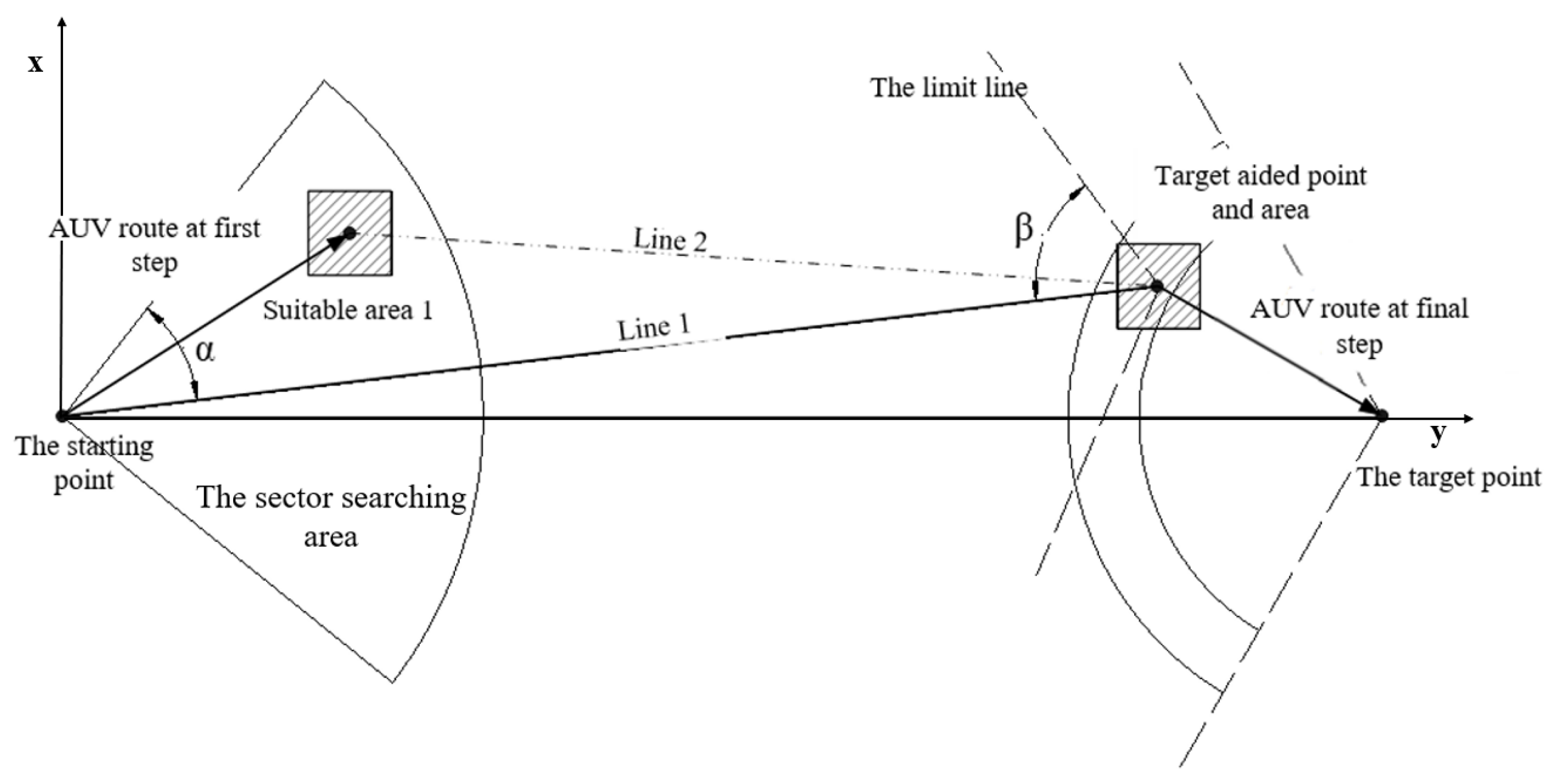
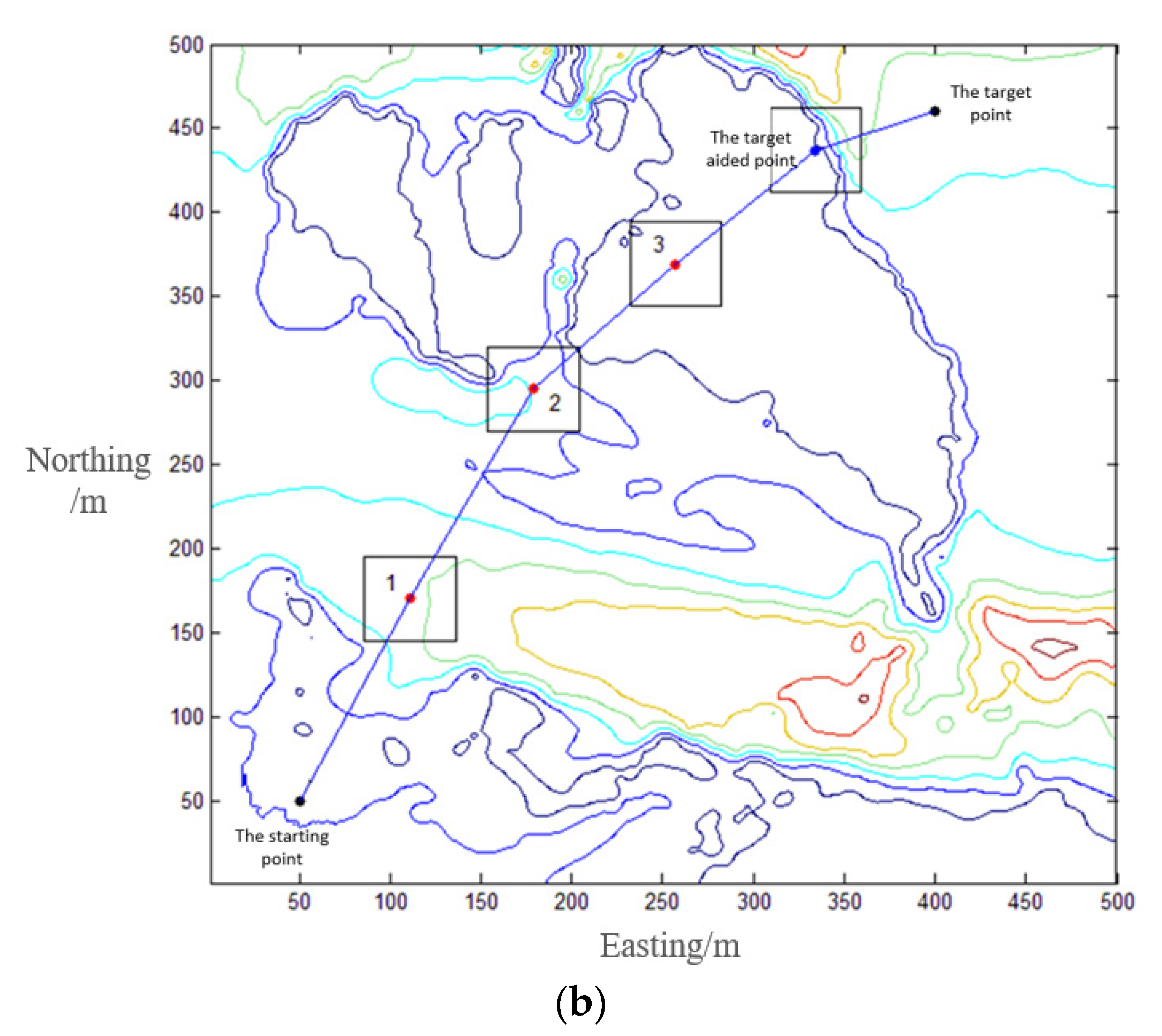
Starting from the start point, the vehicle needs to go through a sequence of TAN-suitable areas to locate itself with a matching algorithm and reduce the INS accumulated error.
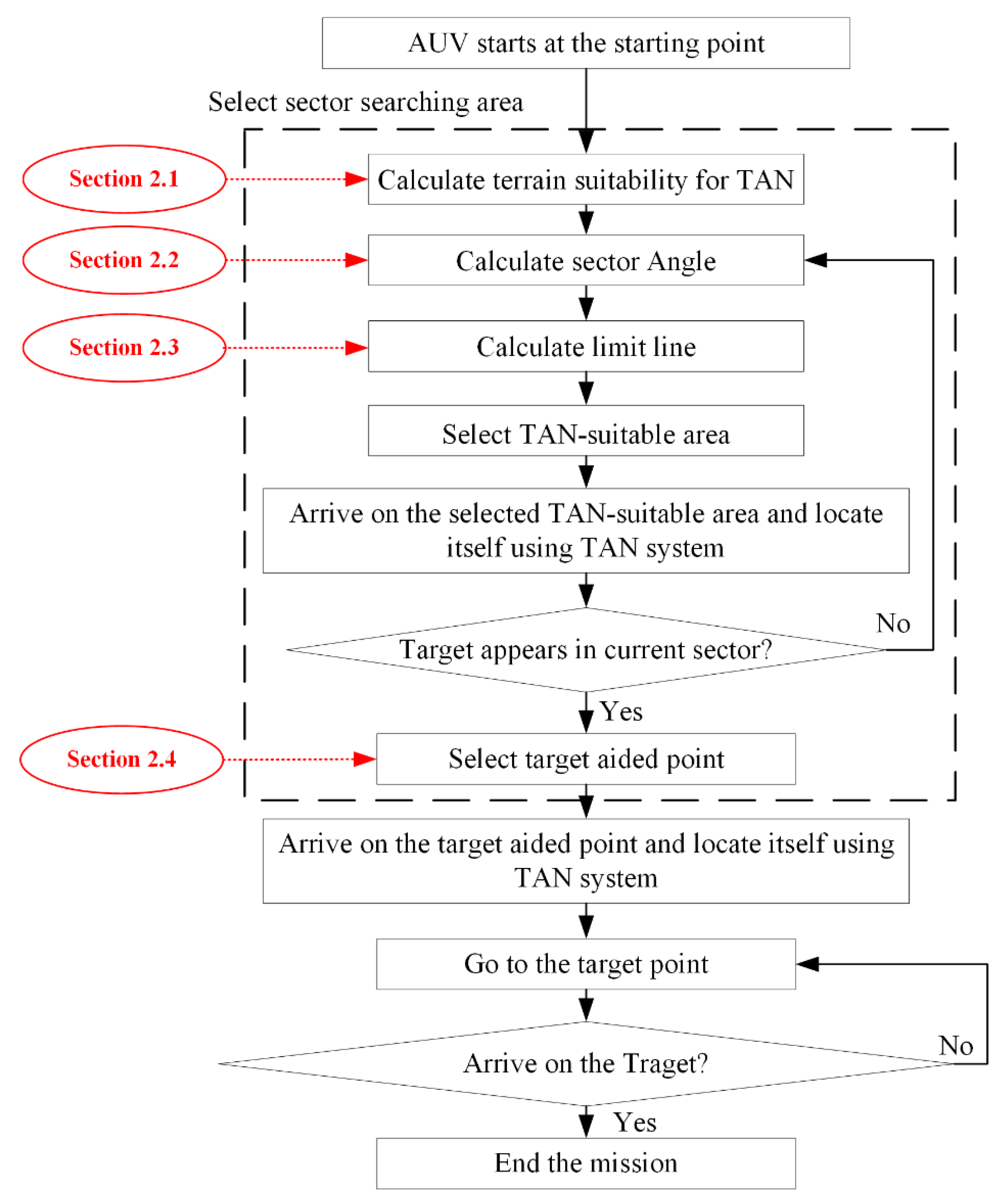
To ensure that the vehicle can reach the target point successfully, a new sector scan method is proposed to analyze the search of the TAN-suitable area. The new method can also ensure a TAN-suitable area exists near the line between the AUV position and the target area. The flow of this algorithm is shown in
Figure 2. In the process from the start to the end of the mission, AUV first needs to select the sector searching area, including the calculation both terrain suitability for TAN (described in
Section 2.1) and the sector angle
Section 2.2), analysis of the limit line (
Section 2.3) and the selection of the TAN-suitable area (the target aided point, a special TAN-suitable area, has been described in
Section 2.4). When AUV reaches the TAN area, the TAN system is used to know whether it reaches the target point. If not, repeat this method until it reaches the target point.
2.1. Sector Searching Method for the TAN-Suitable Area
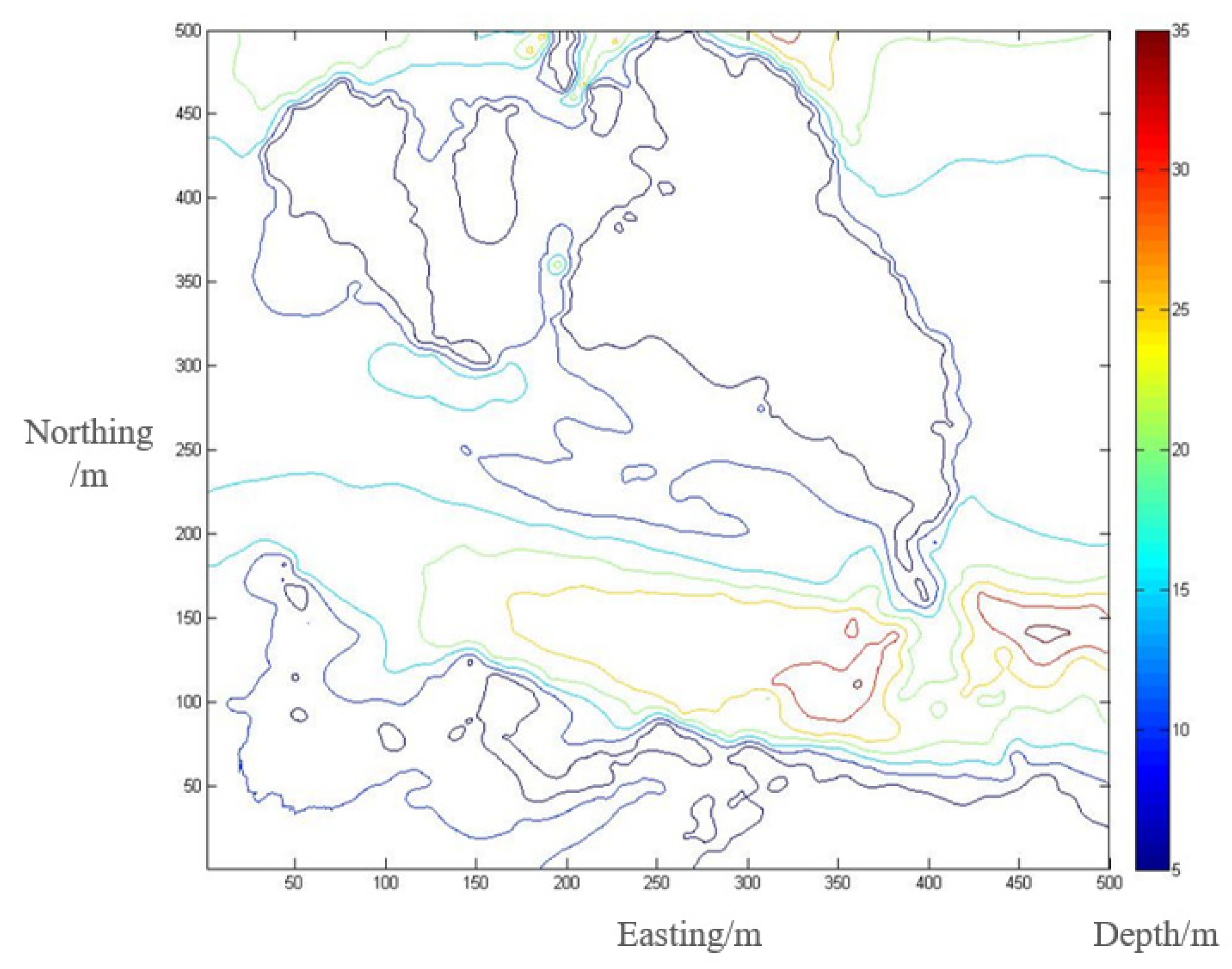
The first step of the proposed method is to calculate the TAN suitability for each block over the priori map. A TAN-suitable area is defined as a fixed size area with sufficient topographic features to enable the accurately positioning of TAN. The terrain elevation entropy is a commonly used index to evaluate the complexity of topographic relief, which means a TAN-suitable area should have a terrain elevation entropy,
, bigger than a given threshold. According to Ref. [
6], the terrain elevation entropy,
, for an area with a size of
can be given by:
where
denotes the terrain depth at
, and
is a process value, make
unaffected by the mean value of terrain depth
. The threshold of
is the median value of terrain elevation entropy calculated in each block over a priori map.
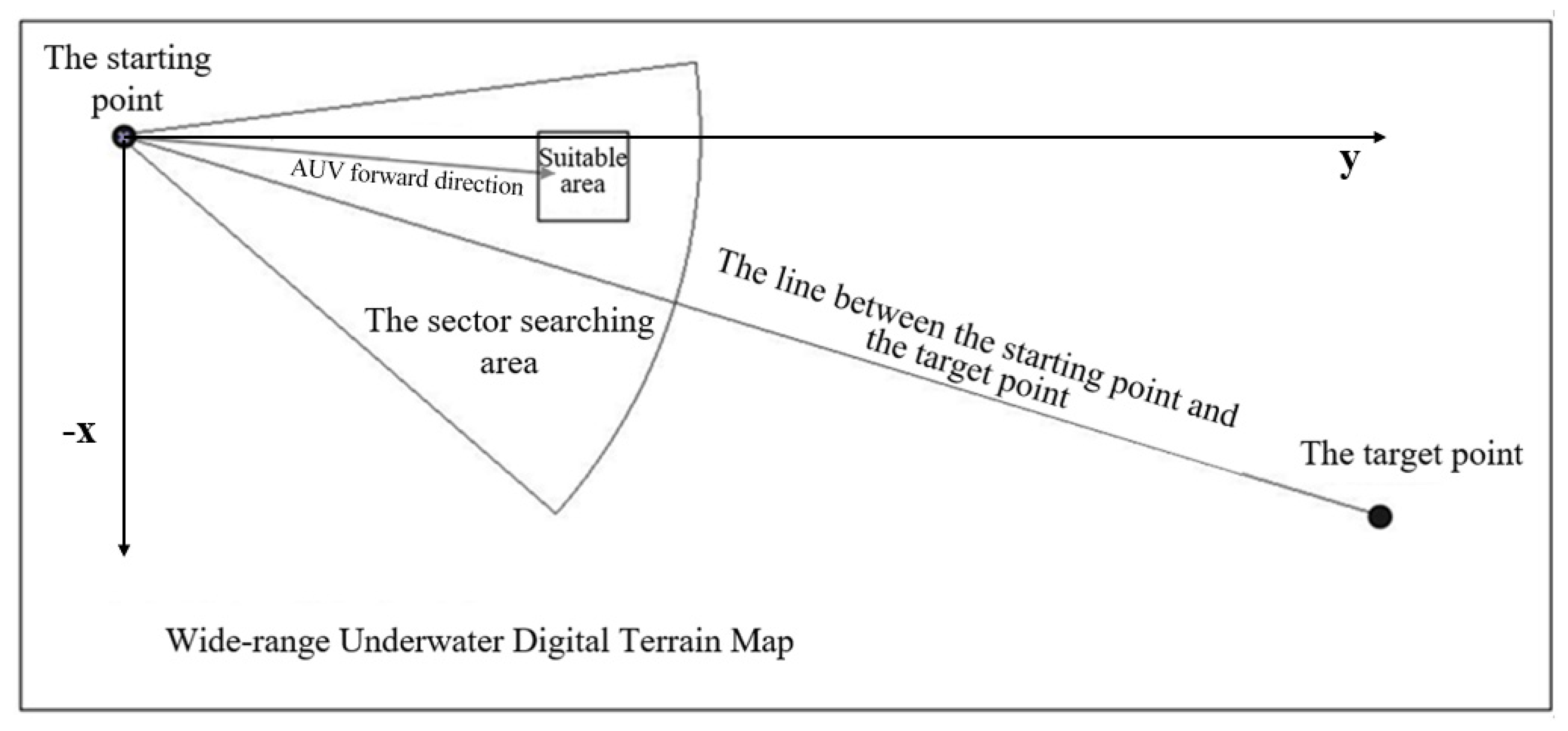
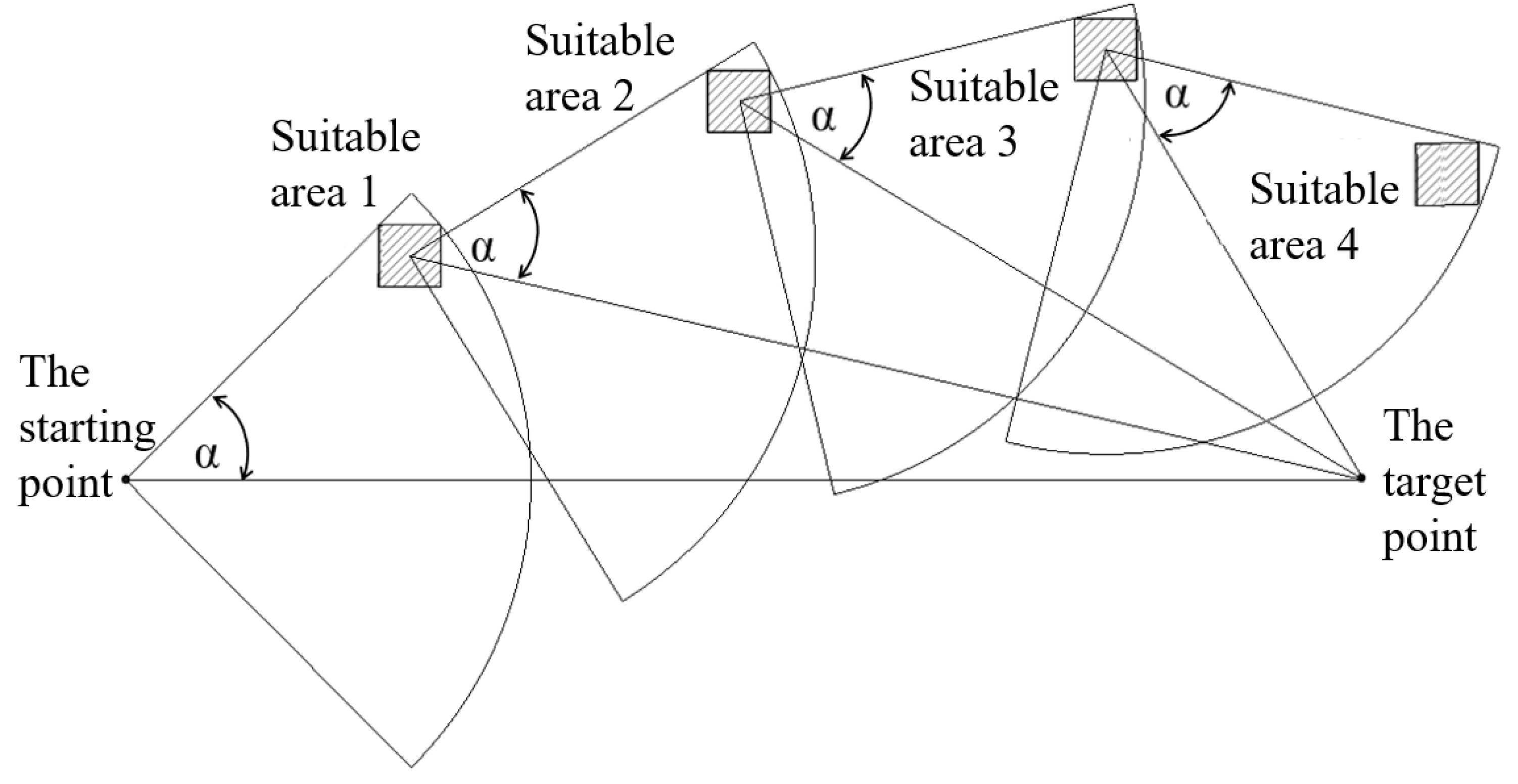
After determining the selection criterion of the TAN-suitable area, a sector searching method is proposed. As shown in
Figure 3, the sector has a circle center of the current position of the vehicle (the starting point in
Figure 3 at the initial time), and it is axisymmetric to the line between the current position of the AUV and the target point.
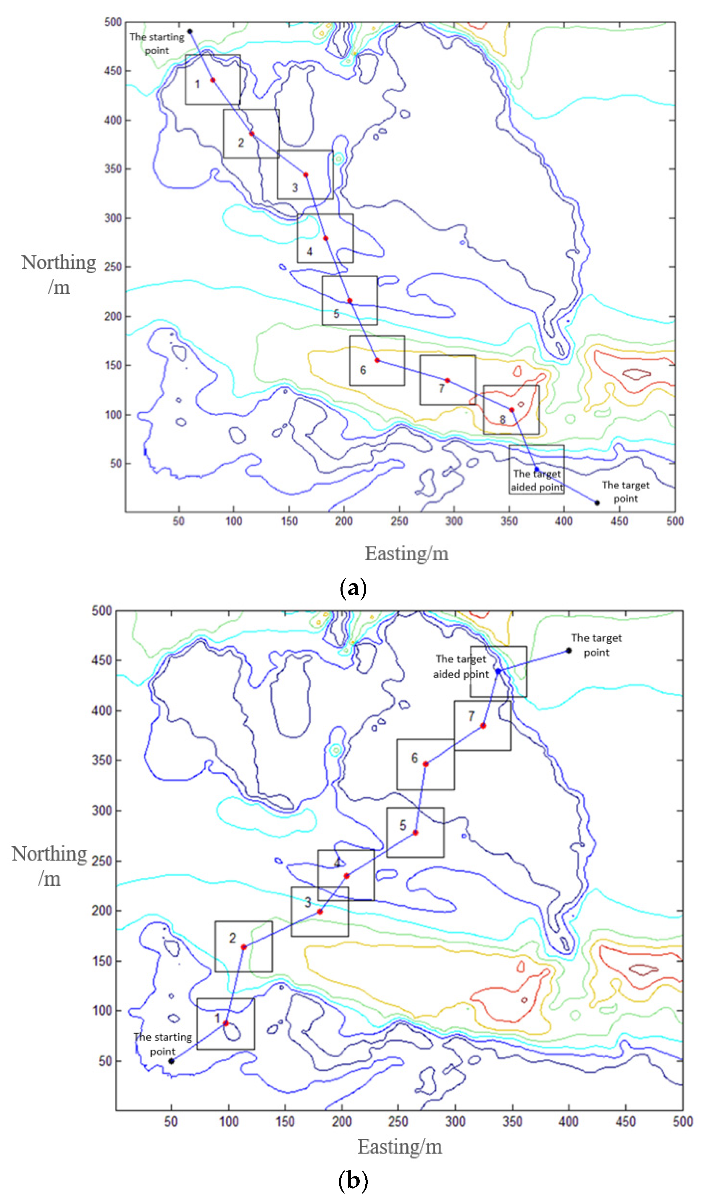
The flow of the TAN path planning algorithm is as follows: The method starts running at the starting point and draws the first sector, to search a TAN-suitable area in this sector. The central point of the TAN-suitable area is taken as the next-goal of the vehicle. When the positioning result given by INS is close to the target point (the distance between the goal and the vehicle’s position yield by INS is less than M/2), the vehicle will scan the terrain using a multi-beam echo sounder (MBES) and generate a gridded bathymetric map with a size of
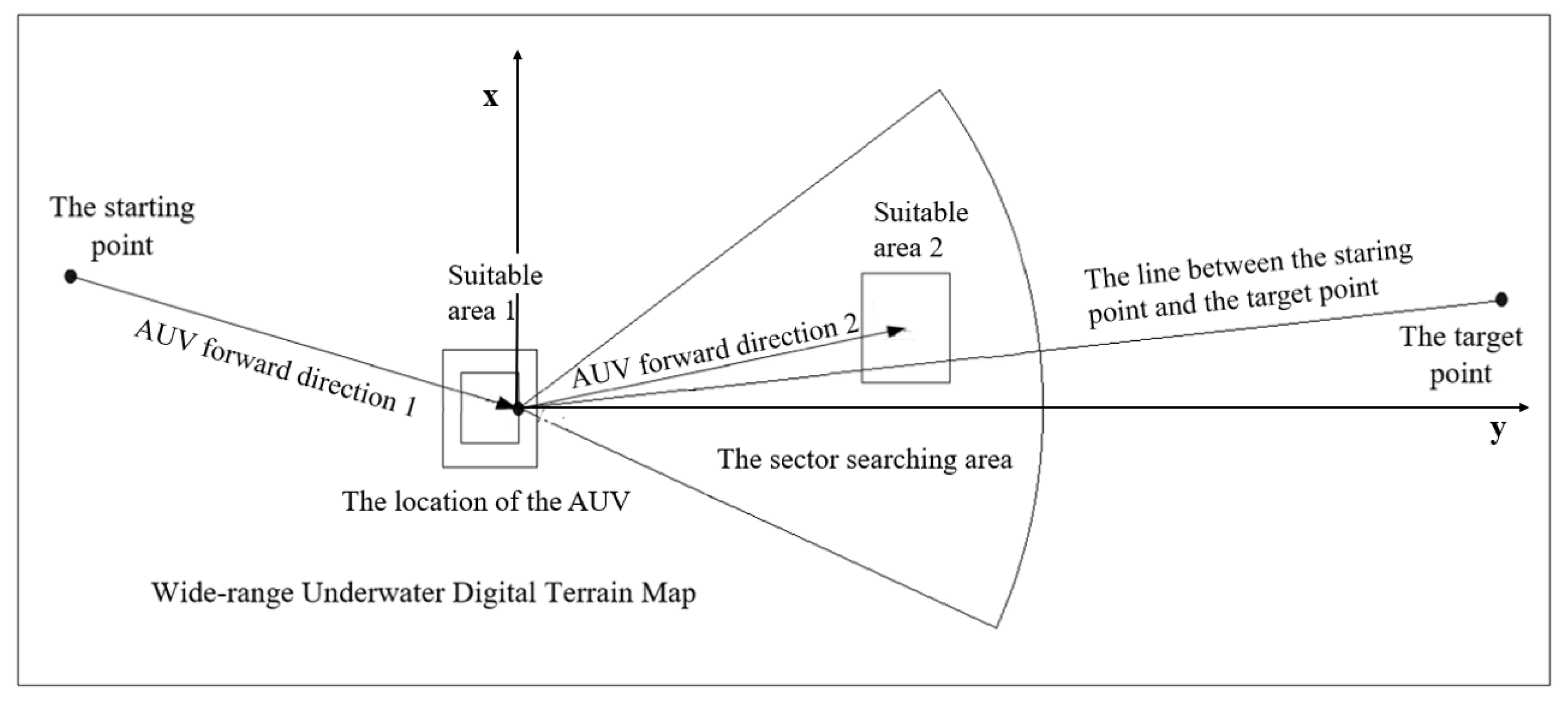
. Then TAN system can yield an estimate of vehicle’s position by fusing the INS data and the terrain matching results. Taking the current position of the AUV output from the tan system as the center of the circle, a new sector can be drawn. As shown in
Figure 4, these processes continue until the vehicle reaches the final target area or target point. For convenience, the first TAN-suitable area arrived at by the vehicle is TAN-suitable area 1, the next TAN-suitable area arrived at is defined as the TAN-suitable area 2, until the end, as shown in
Figure 4.
In the proposed method, the central angle, the limit line at the target point and the selection of the target-aided point directly restricts the practicability of the search method. Therefore, these parameters will be discussed in
Section 2.2,
Section 2.3, and
Section 2.4, respectively.
2.2. Central Angle of the Sector
With the given TAN suitability calculation equations, TAN suitable areas are chosen in a sector. When the vehicle searches for a TAN-suitable area through the sector searching method, the central angle of the sector has a direct impact on the size of the search area. and the unreasonable sector angle may make the vehicle fail to reach the target area due to a large amount of navigation errors accumulated in the long-distance navigation.
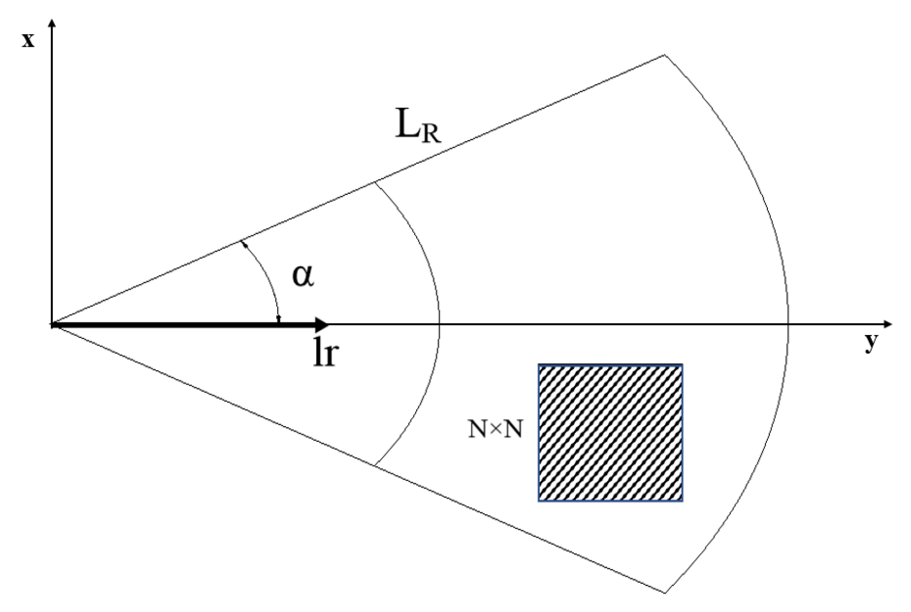
By analyzing the boundary condition of the sector, the calculation of the central angle in the sector searching method is discussed. The parameters within the sector are denoted in
Figure 5.
In
Figure 5,
is the 1/2 of the central angle,
is the radius of the sector, and
is the minimum distance required by the vehicle to meet the rotary motion, while the TAN-suitable area is demonstrated by a square area with a size of
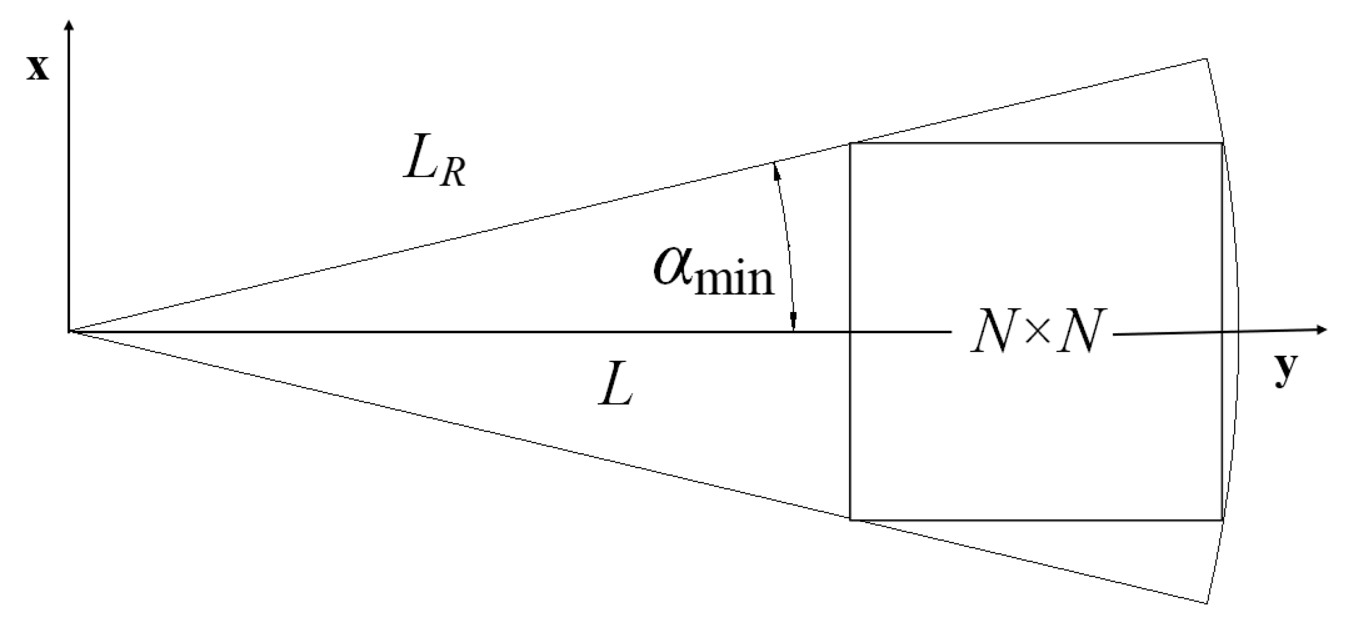
. When only one
block can be included in the sector area, the minimum value
of the half-sector angle can be obtained, as shown in
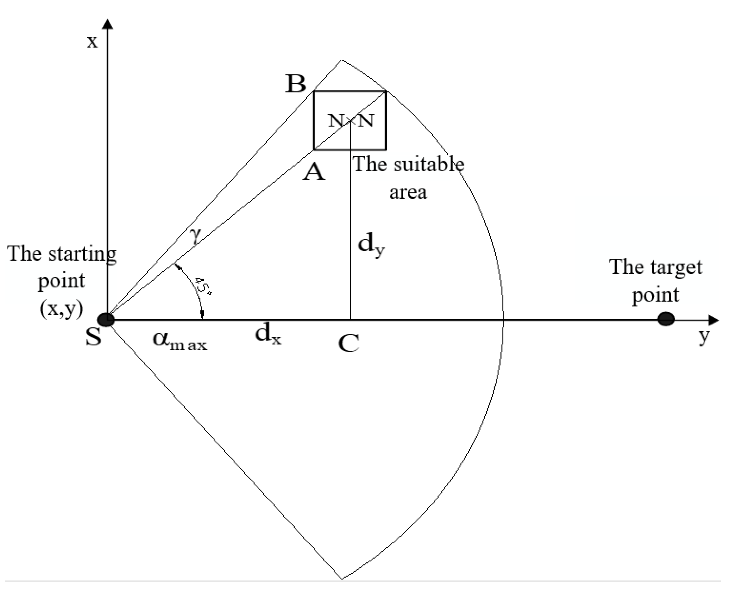
Figure 6. In addition, calculation of
is shown in Equations (2) and (3).
In Equation (3), x and y describe the vehicle’s horizontal position in eastern and northern directions. It can be seen that the minimum central angle of the sector is determined by the size of the TAN-suitable area and the radius of the sector. However, when the central angle is set to the minimum value, only one area can be in the searching area, making it difficult to find a size TAN-suitable area in the sector.
Assume that the sector radius
can be denoted as:
combined with Equation (4), Equation (3) can be rewritten as:
From Equation (5), decreases as the coefficient k increases. Therefore, selecting an appropriate coefficient k is helpful to expand the area of the sector.
Here, we denote the there is a minimum value
and a maximum value
at the 1/2 central angle of the sector. To enable the AUV to effectively move towards the target area,
should be limited by a maximum value range. Otherwise, in the case of the TAN-suitable area is at edge, as shown in
Figure 7a, the vehicle will have a large movement in the vertical direction of the line between the starting point and the target point, which will make the vehicle waste more energy and is not conducive to the large-scale transfer and movement of the vehicle. As shown in
Figure 7b, the movement distance of the vehicle perpendicular to the line direction of the starting point and the target point is smaller than that of the line direction, which ensures that the vehicle can efficiently transfer and move to the target point.
To ensure that the movement distance of the vehicle along the line direction
between the starting point and the target point is greater than that in the other direction
(that is,
), it is necessary to calculate an appropriate value of
, and the value of
at condition
is shown in
Figure 8.
As shown in
Figure 8,
and
, then
According to the law of cosines
if
and
,
can be calculated as
where the value of
k needs to satisfy
Then Equation (8) can be solved with
. In addition, according to Equation (8), when
,
Equation (10) indicates that, when
, the limit value of
is 45°, which is also the minimum value of
. Therefore, in practical application, the 1/2 central angle
of the sector should not exceed 45°. Combining with Equations (4) and (5), the range of the 1/2 central angle of the sector is calculated as follows:
In addition, the value range of
k calculated according to Equation (9) still cannot be applied in practice. Because only when
k satisfies Equation (9), the corresponding value of
exists. The value range of
k is calculated considering that the position of the TAN-suitable area should be at the edge of the sector scan area in the calculation process, and angle
is assumed to exist. Therefore, in practice, the value of
k only needs to satisfy Equation (5), and the value of
k can be obtained as follows:
The Equation (12) has given the minimal central angle of the sector. For a sector which do not satisfy the Equation (12), the area of the sector is too small to contain even one block, making it impossible to find a TAN-suitable area with a size of in this sector.
2.3. Limit Line at the Target Point
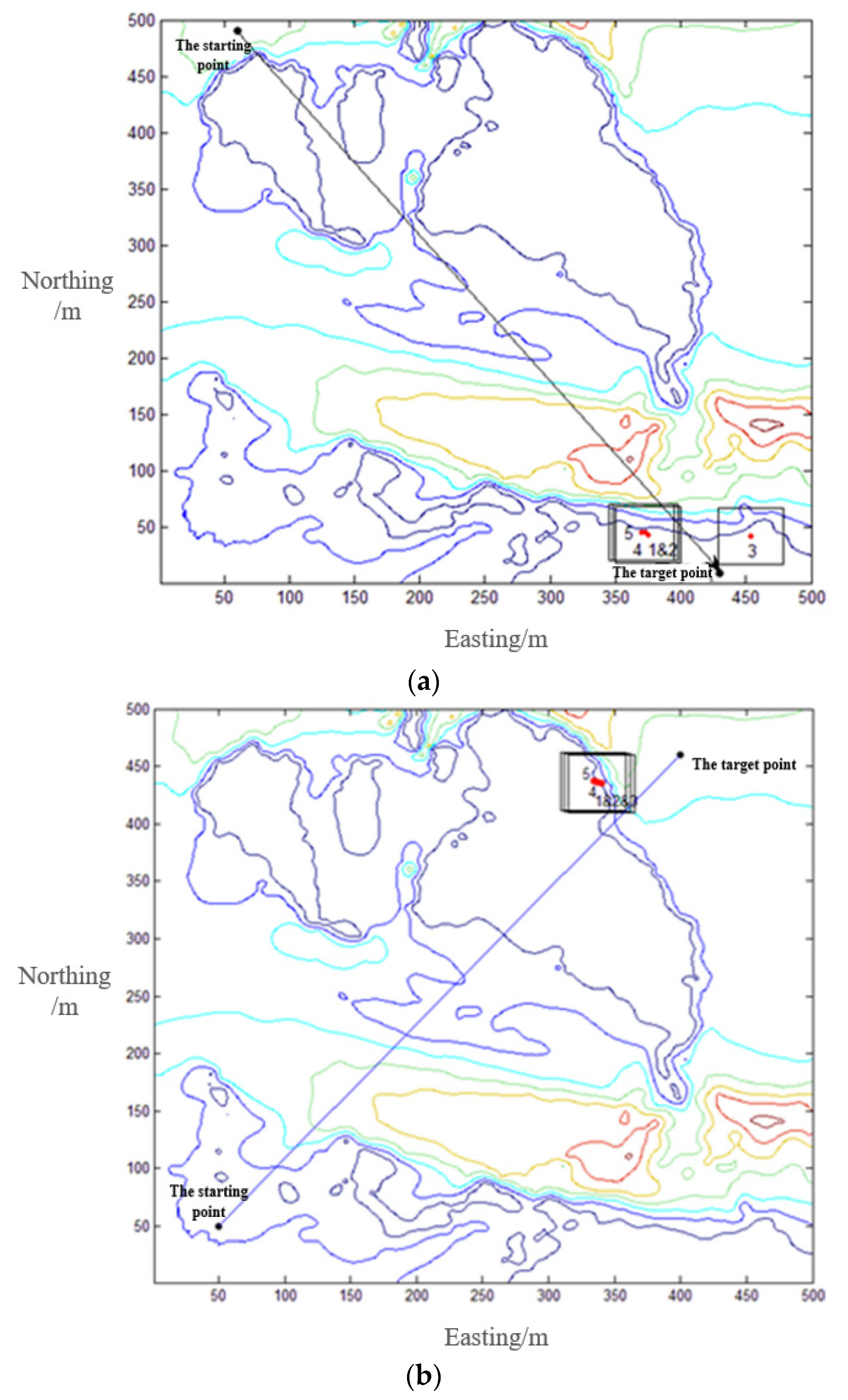
The limit line is proposed to reduce the time taken for an AUV to reach the target point. When the sector searching method is used for path planning, there is another limiting case, that is, the TAN-suitable area obtained by search is always at the edge of the sector scan area and on the same side of the sector. In this limiting case, the vehicle starts from the starting point, and if the 1/2 central angle of the sector is a constant value
, the TAN-suitable area will cross the target area or target point after several selections of TAN-suitable areas. At this time, the TAN-suitable area obtained will appear behind the target area, as shown in
Figure 9.
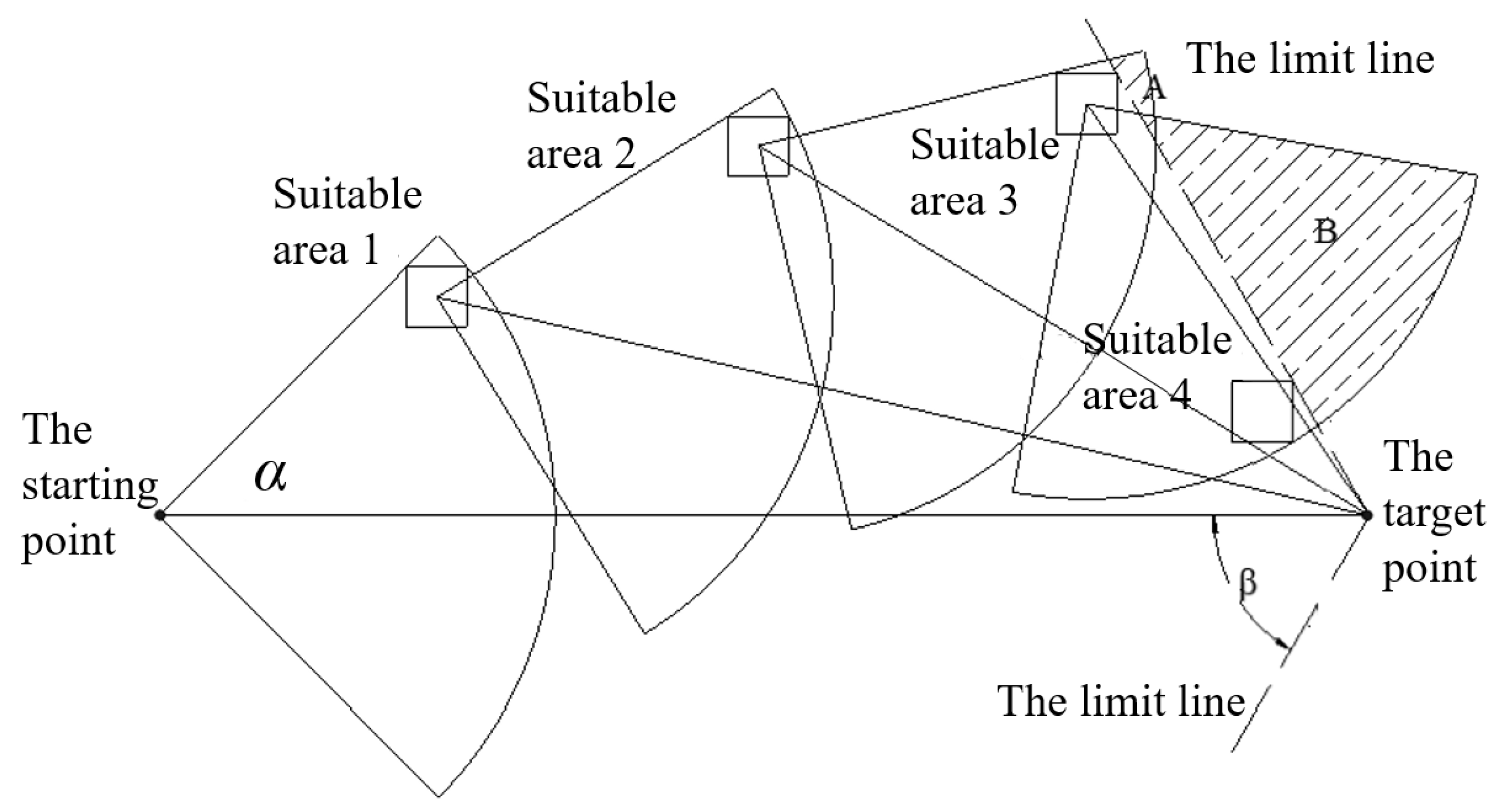
To avoid that, the path planning method will select to arrive on TAN-suitable areas which behind the target area, a method is proposed to restrict the sector searching area near the target. As shown in
Figure 10, with the target point as the center point and the line between the starting point and the target point as the centerline, two limiting lines with an angle of
with the center line in the direction of the starting point is constructed. All the TAN-suitable areas are required to be within the angle between the two limit lines. The shaded areas
A and
B in the
Figure 10 are the scan areas that have been deleted due to the appearance of the limit lines.
At the target point, the existence of the limit lines can make the position of selected TAN-suitable area converge to the target point when the vehicle is close to the target point. At the same time, it can prevent the TAN-suitable area obtained by searching from crossing the target point and appearing behind the target point, while avoiding the vehicle from making redundant rotation movement simultaneously.
To prevent the TAN-suitable area from appearing behind the target point, the maximum angle
in
Figure 10 between the limit line and the line of the starting point and the target point should not exceed 90°. When
= 90°, the limit line is perpendicular to the line of the starting point and the target point.
At the same time, to make the range of the sector scan area are large enough and ensure the convergence of the searched TAN-suitable areas, the method similar to the value analysis of
is adopted, which can be concluded that the angle
between the limit line and the line between the starting point and the target point should be no less than 45°. That is, the value range of
is:
2.4. Selection of Target-Aided Point
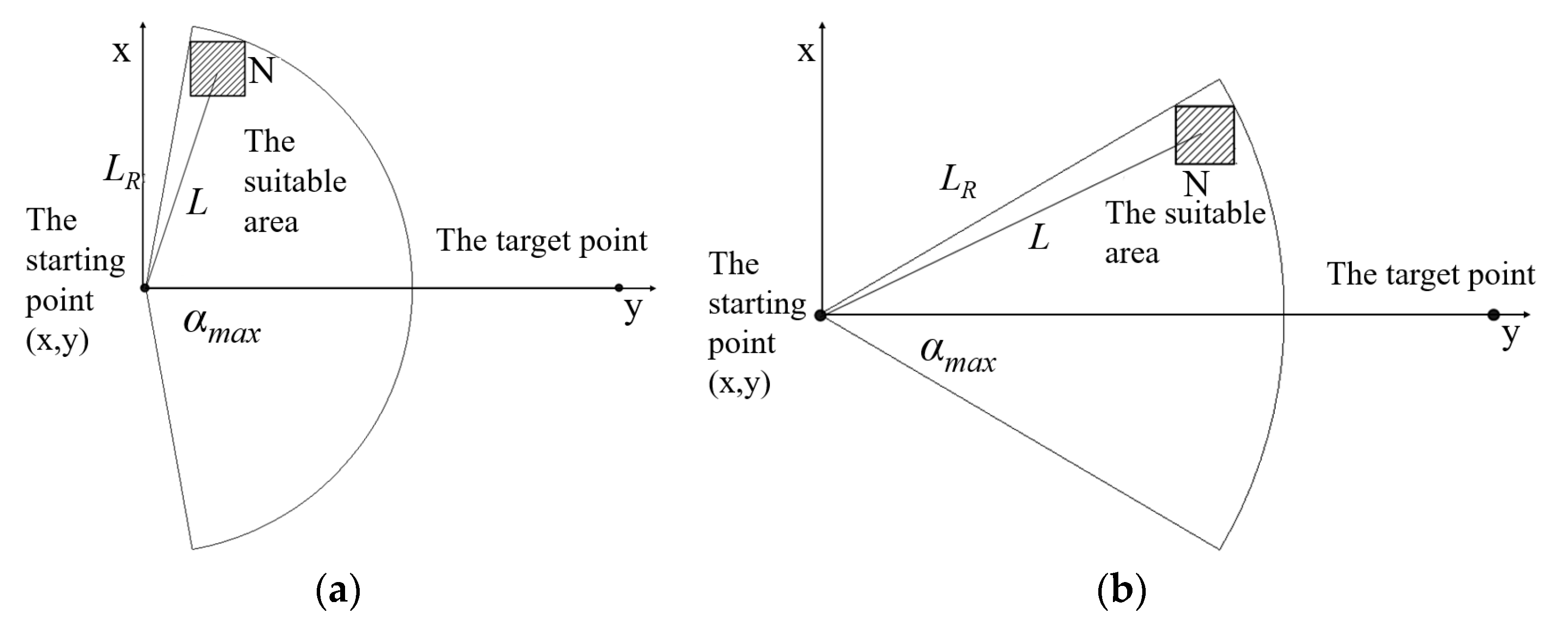
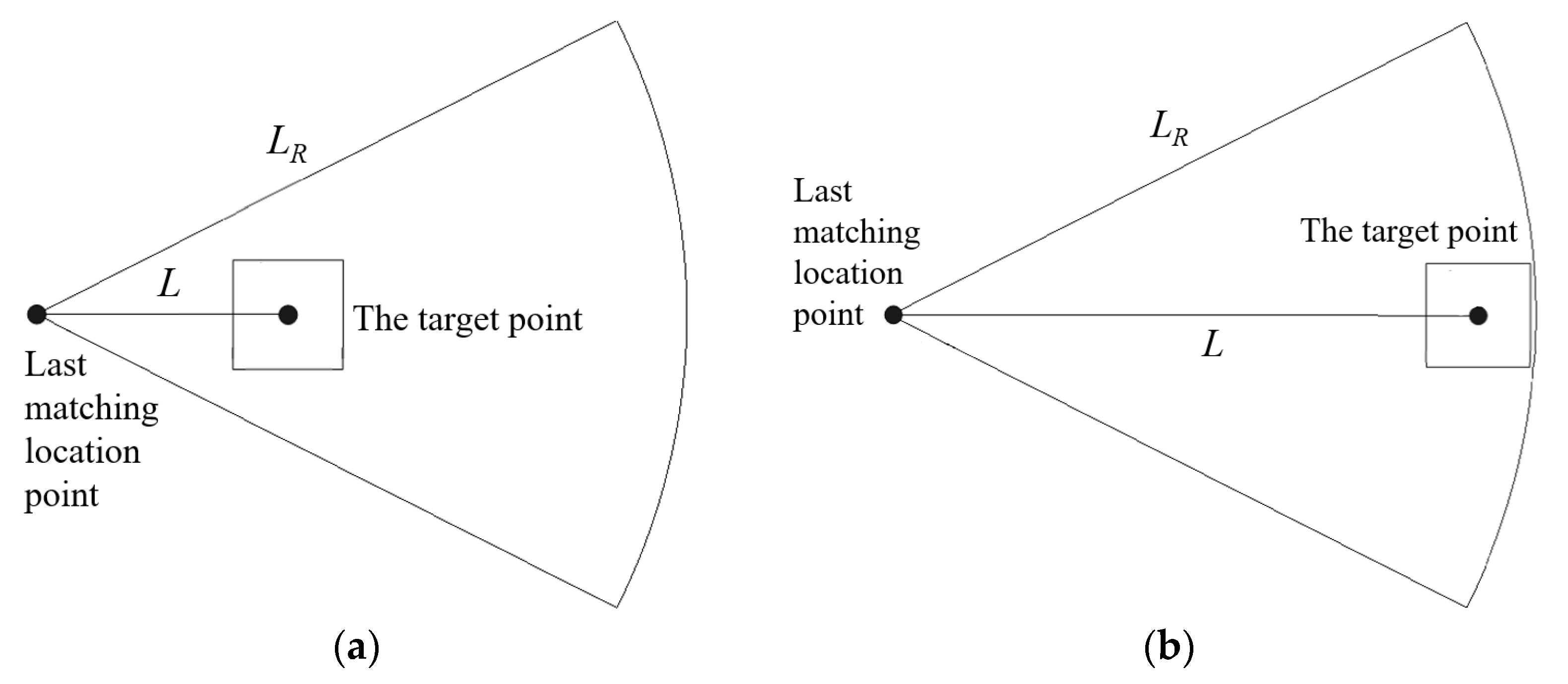
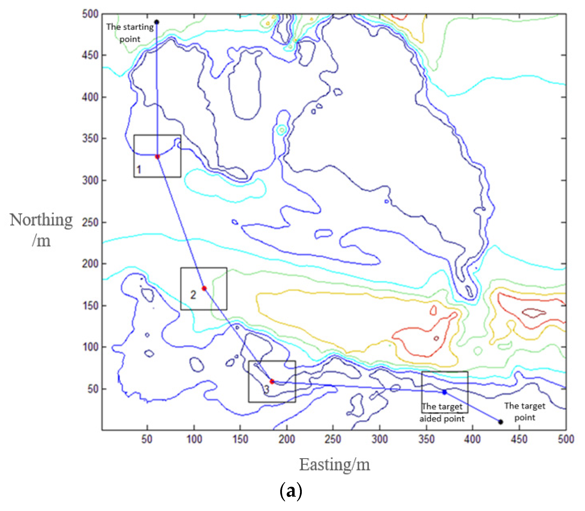
The final step of the proposed method is to find out a target aided point around the target. In some special mission such as seabed equipment installation, the vehicle should arrive in the target point extreme accurately. However, TAN cannot yield an accurate location for a vehicle when the terrain in the target area is flat. The vehicle should arrive on a TAN-suitable area around the target to locate itself firstly, and then the vehicle can reach the target position accurately. Target point may exist at the edge of the sector searching area of the vehicle, the long travel distance of the vehicle from current point to the target will result in a large cumulative error when the vehicle reaches the target point, as shown in
Figure 11.
As can be seen from
Figure 11a, a small INS accumulative error at the target point can meets the navigation accuracy requirements of the vehicle, and AUV can directly navigate to the target. However, in
Figure 11b, the vehicle has to travel nearly the entire search radius to reach the target, and the large accumulative error will affect the accuracy of reaching the target point. Thus, an appropriate TAN-suitable area is selected for transition within an appropriate range before the vehicle reaches the target, and the center point of this area is called the target-aided point, as shown in
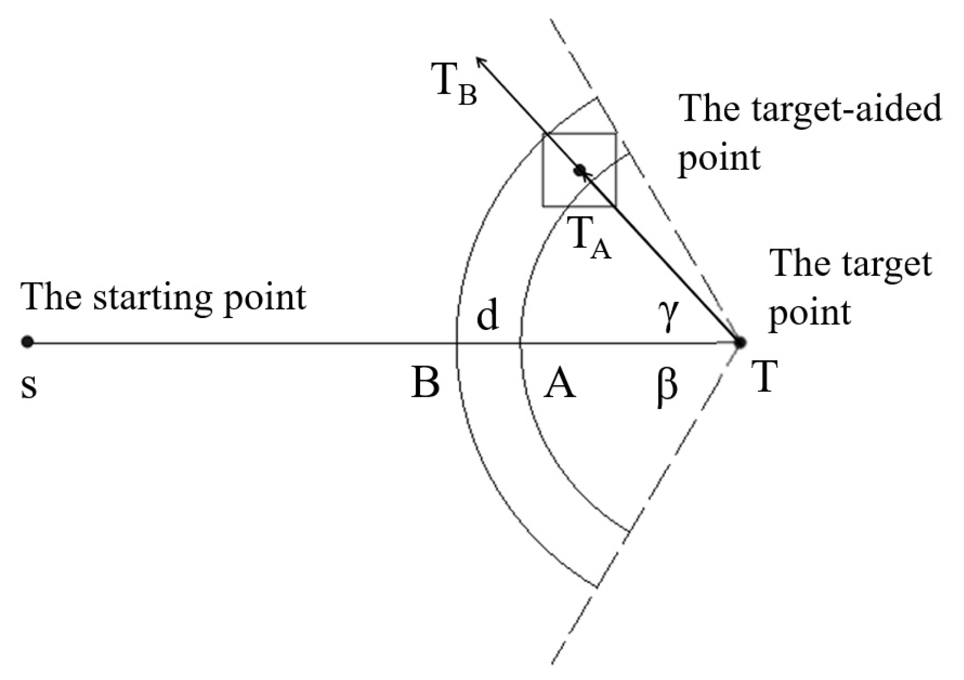
Figure 12.
In
Figure 12, the dotted line is the target exit limit line, and
denotes the limit angle. |
TA| is the minimum distance required by AUV from point
to target
T, which is jointly determined by the turning circle of AUV, the navigation error of the vehicle, and size of the matching scan area. |
TB| is a predefined value that represents the maximum distance set for AUV from point
to target
T, ensuring that the vehicle can search for at least one target-aided point. The defined distance of |
TA| and |
TB| can be calculated as
where
l is the turning circle of the vehicle,
is the estimate on the maximum INS error of the vehicle after driving
distance, and
N has been described in Equation (2).
Then, the value range of distance
L between the target-aided point and the target point is


