1. Introduction
A drone [
1] (UAV—Unmanned Aerial Vehicle) is a type of flying vehicle or unmanned aircraft, aircraft with remote control. Drones can come in many sizes, shapes, and perform many different roles. Their main components include the engine, the central processing unit, the power, the propeller, and the racks. Drones can fly high and up to tens of kilometers. It can be said that the era of drones has come, and these drones are slowly evolving to become an integral part of everyday life. Against this backdrop, industries and governments are racing to find ways to use this emerging technology.
Their main structure includes (
Figure 1): an engine, central processing system, power, propeller, and racks. Drones can fly high and up to tens of kilometers.
Drones are not simply flying devices, they are also a data collection and processing tool–drones are aerial robots [
2]. They are very light, agile, and especially hundreds of times cheaper than bulky ground robots. Drones can easily overcome obstacles and change geographical positions flexibly. The size of drones varies widely, from the size of an adult to those only as big as the palm of your hand. The tasks that these drones can perform are also varied and not the same. Thanks to these advantages, drones have the potential to expand into a large-scale industry, providing multi-industry solutions. Drones can also integrate self-aware technology [
3]—where computers process images and convert what they see into specific behaviors to automate more routine or difficult tasks. for human.
A wide range of industries and businesses are looking to capitalize on the unique advantages of drones, particularly their data collection and processing capabilities. One of the main benefits of drones in business is that they are simply safer than using human labor. From a safety perspective, drones help businesses reduce the need to use helicopters or human workers to climb high-rise structures and conduct inspection operations. In addition, once a fault has occurred and is determined to be due to the drone, the repair will take less time and manpower. The quality of drone models will improve over time, and artificial intelligence (AI) [
4] models will ensure fault detection in minimal time. It is also worth noting that using a drone is very environmentally friendly. The device consumes less energy and emits less than a traditional helicopter, which requires thousands of liters of fuel to operate.
The most mentioned application of drone technology is search and warning monitoring which helps improve safety in people’s daily lives. The trend of using drones in this industry is also increasing. Drones are a perfect complement to traditional means of transport, especially in rural or remote areas that are hard to reach. Thanks to their unique advantages, drones are also gradually playing an important role in emergency situations. They help provide information about disaster situations, crime scenes, and many other factors before anyone reaches the scene. Observers say drones can help provide quick, effective responses to disaster and medical emergencies, including delivering supplies and equipment to victims in areas where there is no such thing as an emergency safe for people to move and approach. Drones can also be deployed before police arrive at the scene to provide initial information about the case, including live footage of the scene and images of the crime. In addition, drones can also help create or check maps [
5], area topography, or support high-tech integrated agriculture.
Smart Drones packed with self-protection and command compliance, precision sensing, and self-monitoring technologies are the next big revolution in the field. With the momentum of modern technology development, the drone will be integrated with many other specialized automated features, ensuring the ability to shoot in the air and on the ground to provide closed inspection solutions. Automation, machine learning, and AI will improve the quality of data collection and verification, ensuring faster drone response and action in the future. With that development prospect, drones promise to provide new opportunities in the fields of transportation, logistics, and many other commercial activities. Experts believe that drones will play a prominent role in everyday life in the not-too-distant future, as their technology becomes more sophisticated and autonomous. The rational use of drones will bring clear positive social impacts such as helping to improve access to healthcare services and equipment in rural and minority communities. This will make this type of drone more receptive to the public, thereby paving the way for many other applications of drones.
Since the 20s, fuzzy set theory and artificial neural networks have developed rapidly and are of interest. With fuzzy logic, artificial intelligence has developed strongly, creating the basis for building expert systems, which are capable of providing system control experience. Artificial intelligence is built on top of artificial neural networks. The combination of fuzzy logic and neural networks in the design of automatic control systems is a completely new trend, the direction of intelligent control system design, a system where the controller has the ability to think like a controller. The human brain can self-learn and re-adjust itself to the unpredictable changes of the subject. As known, fuzzy systems and neural networks are both capable of working in unstable, inaccurate systems and extreme environmental conditions. Fuzzy systems and neural networks have many examples to evaluate and compare them. Nowadays, designers have widely and systematically applied fuzzy logic and neural networks in the field of cybernetics. The idea is to cancel out the disadvantages and gain the advantages of both technologies, this means that the two technologies combine to maximize the strengths of each and complement the disadvantages to form one. The new system is more optimized. This unified system will have the advantages of both: Neural network (learning ability, optimization ability, structural connectivity) and a fuzzy system (human intelligence through fuzzy if-then rule, the advantage of having a close understanding of the expertise of experts).
In fact, the development of drones in the last 10 years is a tremendous development. Presence in almost all areas of life from medical [
6], agriculture [
7], delivery [
8], entertainment [
9], military [
10], etc. In the maritime sector is no exception, so drones at sea [
11] are also an area that needs attention. Apart from that, in the first decade of the 21st century, machine learning was strongly researched and developed, marking an important turning point that changed the research foundation of Artificial Intelligence. Machine learning involves building computer programs that can automatically acquire knowledge, improve their abilities through experiences, and study the principles of the learning process [
12]. The results and technologies of machine learning are demonstrated through diverse practical applications in areas such as natural language processing, computer vision, search and recognition, robotics, data mining, etc. In all, intelligent control is one of the outstanding topics that is highly effective, and the art of modern human-drone interaction [
13] increases. So, the author wants to use a smart method to control the Drone. This study presents a Neural network for supervisory control–the Fuzzy control algorithm–one of the highly effective hybrid controllers [
14,
15,
16] in recent years, making machine control become more efficient. more efficient and stable towards intelligent artificial intelligence capable of reasoning like humans. This controller can control mechanical devices such as robots, automatic cars, etc., and in this article, the problem is to stabilize altitude and track the trajectory [
17,
18,
19] of drones using a Neural-Fuzzy hybrid controller. The operation of Marine Rescue Drones is often unstable due to many external factors, for example, wind is one of the main confounding factors to the Drone’s flight trajectory, and the implementation of altitude control and Trajectory control set plays an important role. Therefore, the author proposes an algorithm to control the altitude and track the Marine Rescue Drone’s trajectory using a Neural network- Fuzzy controller [
20,
21,
22,
23,
24] that is to use a neural network controller in combination with a fuzzy controller to update the parameters of the drone dynamic PID controller (the coefficients Kp, Ki, Kd are updated continuously thanks to the learning of the proposed controller). The learning of the Neural network and the inference of the fuzzy controller is a combination. It is more convenient when the set does not need expert intervention in the fuzzy controller, but it will be transferring data from the neural network and vice versa. The neural network control algorithm combining fuzzy control and PID control is simulated on Matlab/Simulink. The results obtained from both controllers obtained after conducting the simulation are compared with each other so that the reader can see the difference when applying these two controllers in Marine Rescue Drone.
The controller introduced by the author in this study has the following characteristics:
Brings high efficiency in adjusting the Drone to follow the set trajectory.
Suppress the effect of noise at a high level with high efficiency.
Reduce the operator’s responsibility thanks to the high learning nature of the controller, making it easier to control.
High practicality and is a premise for the development of research on actual operation models.
2. Drone Model
2.1. Structure of Drone
A Drone is a device composed of parts: control motor, central processor, propeller, antenna, bracket, battery, and camera. Users can control the Drone by remote controller or pre-programmed according to GPS-based routes and coordinates.
The Drone controller has a similar structure to the remote controls of the model aircraft, including two buttons and a collapsible antenna. They usually use 2.4 GHz radio waves. However, there are also some controllers that combine both 2.4 GHz and Wi-Fi signals, which can also be based on a control app running on mobile devices.
Conventional Drones can fly thanks to the power from the battery supplied to the propellers. However, today there are expensive high-end models that use jet engines instead of traditional propellers, which can fly up to 800 km and up to 15 km high. Some types of drones work by pre-programmed operation, others are operated by humans using a remote control panel.
A Drone has a compact and lightweight design, which is also the reason why it can be carried easily and conveniently. In addition, it also helps Drones to fly longer in the air. A Drone also has outstanding features such as high mobility, convenience, and effective operation. Smaller and more efficient microprocessors, ever-improving wireless communications, and more diverse and multi-purpose Drones have opened up opportunities for Drones. thrive with more useful applications.
2.2. Dynamics Model of the Drone
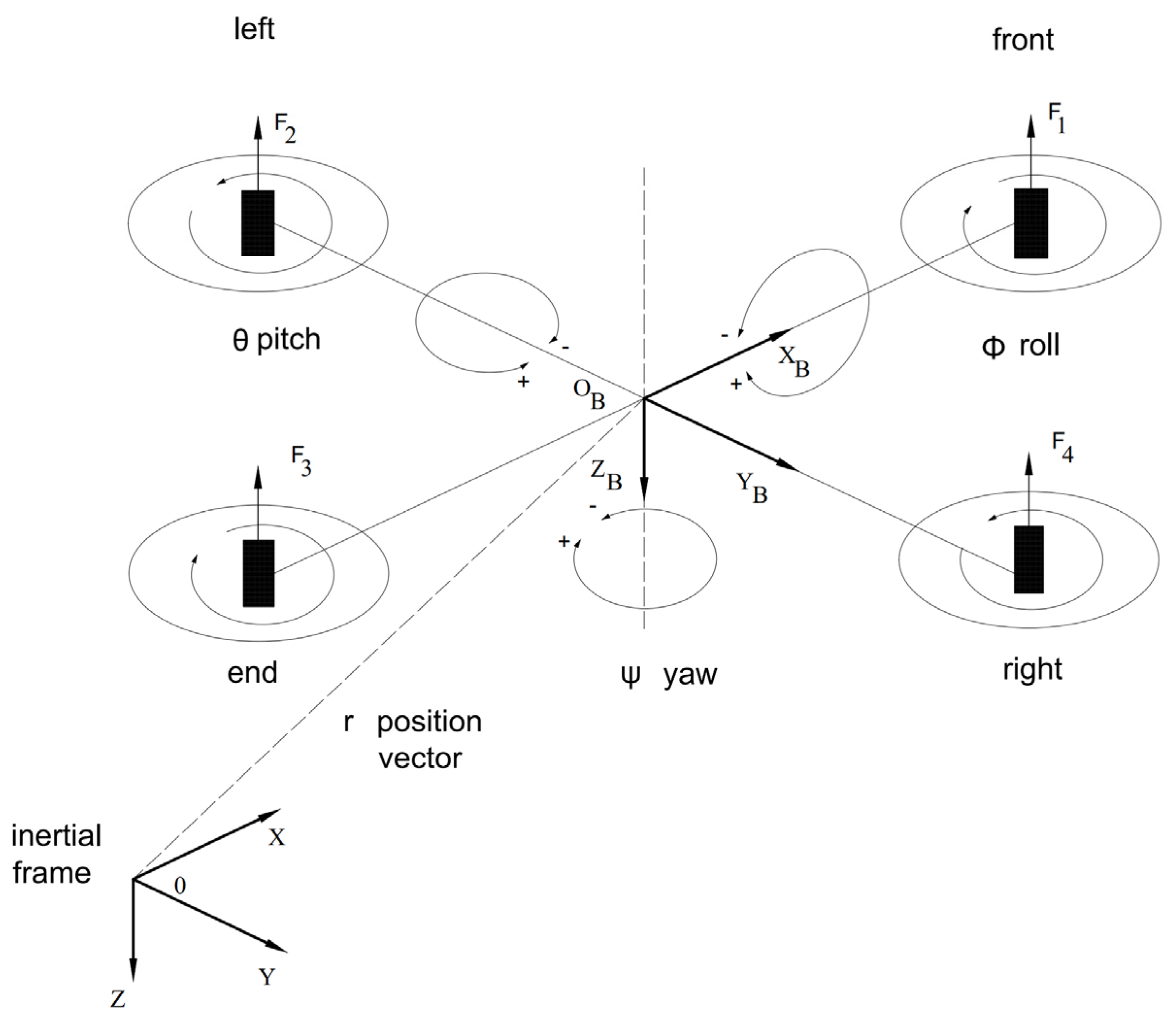
To learn about the kinematic model of the drone Drone, we first determine the coordinate systems that will be used. In
Figure 1, we have the Oxyz coordinate system, which is a global coordinate system (earth reference frame) fixed at a location on the ground.
is a local coordinate system (body reference frame) mounted at the center of the Drone with the
axis toward the 1st motor (Front motor), the
axis towards the 4th motor (Right motor), the
axis pointing down land.
A Drone usually consists of movements: up/down motion (attitude), motion around the
x-axis-roll movement, motion around the
y-axis-pitch movement, and motion around the
z-axis-yaw movement (
Figure 2). By varying the speed of the engines, it is possible to create the movements of the Drone.
In this study, a mathematical model of a Drone [
17,
19] is developed along with its dynamics. The basic equation of motion and force of the Drone is removed and the design parameters for a given Drone are selected. The model is made non-linear for the Drone based on the equation of motion [
22,
23] and the force of the moment using the Newton-Euler method:
where:
—position at the North pole, South pole, the attitude of the Drone in the earth coordinate system;
—are the velocity of the Drone toward the x, y, z axis, respectively;
—are the rotation around the x-axis (Roll angle), y-axis (Pitch angle), z-axis (Yaw angle);
—are the rotational velocities around the x, y, and z axis, respectively;
—acceleration due to gravity;
—cosine; —sin;
—Corresponding thrust of 4 propellers;
—are the moments of inertia of the drone;
—mass of Drone.
2.3. Overview Neural Network–Fuzzy Logic Controller
First of all, we immediately see that both fuzzy controllers and neural network controllers are, in principle, static, nonlinear controllers. They can be designed with a given system quality to arbitrary precision and work according to the principles of human thought.
The performance of a neural network is determined by the type of neurons used and the network structure that connects those neurons together. It is completely independent of the object being controlled. Even if the designers have knowledge and understanding of the object, it will not help in the selection of neurons and the construction of the network structure. In contrast, for the fuzzy controller designer, knowledge and understanding of the object is very necessary. Although these insights are not necessarily represented in the form of a mathematical model describing the object, but can only be experiences gained in the process of approaching the object, without them, the designer is not possible to build a composition rule, can not blur the signal value (determine the membership function). The reality of fuzzy controller design shows that designers are always most confused when building functions belonging to language value descriptions. The reason is that while the association rule is built on the basis of only needing to have a qualitative understanding of the object (which is a fundamental advantage of the fuzzy control principle), the determination of the membership function for each linguistic value is not sufficient. Again, it requires detailed quantitative knowledge (although it is limited to the input and output signal value of the object), which is the key point to distinguish fuzzy control from classical control, and also, the basic point of the neural network.
Even when it was first designed, neural networks had no knowledge. Its knowledge is formed through the learning phase through learning patterns. The better the learning sample, the more diverse, and the more cases, the closer the initial knowledge of the network is to reality. If that is not enough, the knowledge of the network can still be added, and further perfected in the process of working with the object. With the fuzzy controller, the opposite is true. When the design is complete, the fuzzy controller has a certain working mechanism immediately and this mechanism will not change and be kept fixed throughout the working period. In other words, the neural network is capable of learning and the fuzzy controller is not.
The neural network is still considered an application solution in which the designer is “blind” to the object (black-box solution). The knowledge of the network lies in the weights that are evenly distributed throughout the network. A small change in the weights is not enough to change the performance of the neural network, so it is difficult to evaluate the existing knowledge of the network without a comparison sample. Fuzzy controllers are different, a small change in the membership function, or composition rule, will immediately lead to a corresponding change that is very noticeable in its nature. Therefore, the fuzzy controller has higher real-time adaptability than the neural network.
Thus, it is clear that the advantages of neural networks are disadvantages of fuzzy controllers and vice versa. The following table (
Table 1) summarizes the advantages and disadvantages of the two controllers.
To explain the task of the Neural Network and Fuzzy Logic Control in the proposed Neural-Fuzzy control system in
Figure 3 and
Figure 4:
In
Figure 3 and
Figure 4, it is easy to see a neural fuzzy system is characterized by the use of neural networks to provide fuzzy systems with a kind of automatic tuning method, but without altering their functionality. In this study, connecting the fuzzy controller and neural network is a form of serial coupling. This form of coupling is very suitable for problems where the neural network is responsible for processing input and output signals for fuzzy controllers.
Neural networks have a major drawback of their “black box” nature. Data is fed into the network, computation occurs, and results are output. However, we don’t know exactly what happened.
Fuzzy logic is the opposite, their rule sets are very close to human knowledge. However, fuzzy logic does not have the self-learning ability of neural networks. Fuzzy rules and membership functions can only be adjusted manually.
Therefore, the combination of neural networks and fuzzy control has invisibly eliminated their shortcomings, creating a neural-fuzzy controller with outstanding advantages.
The following table shows the strengths and weaknesses of Neural networks and Fuzzy Logic Control. For the reasons mentioned above, the combination of these two control methods is a perfect complement to each other. The new hybrid controller is more efficient and intelligent.
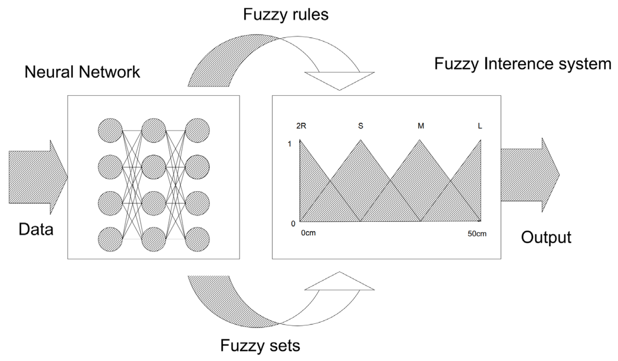
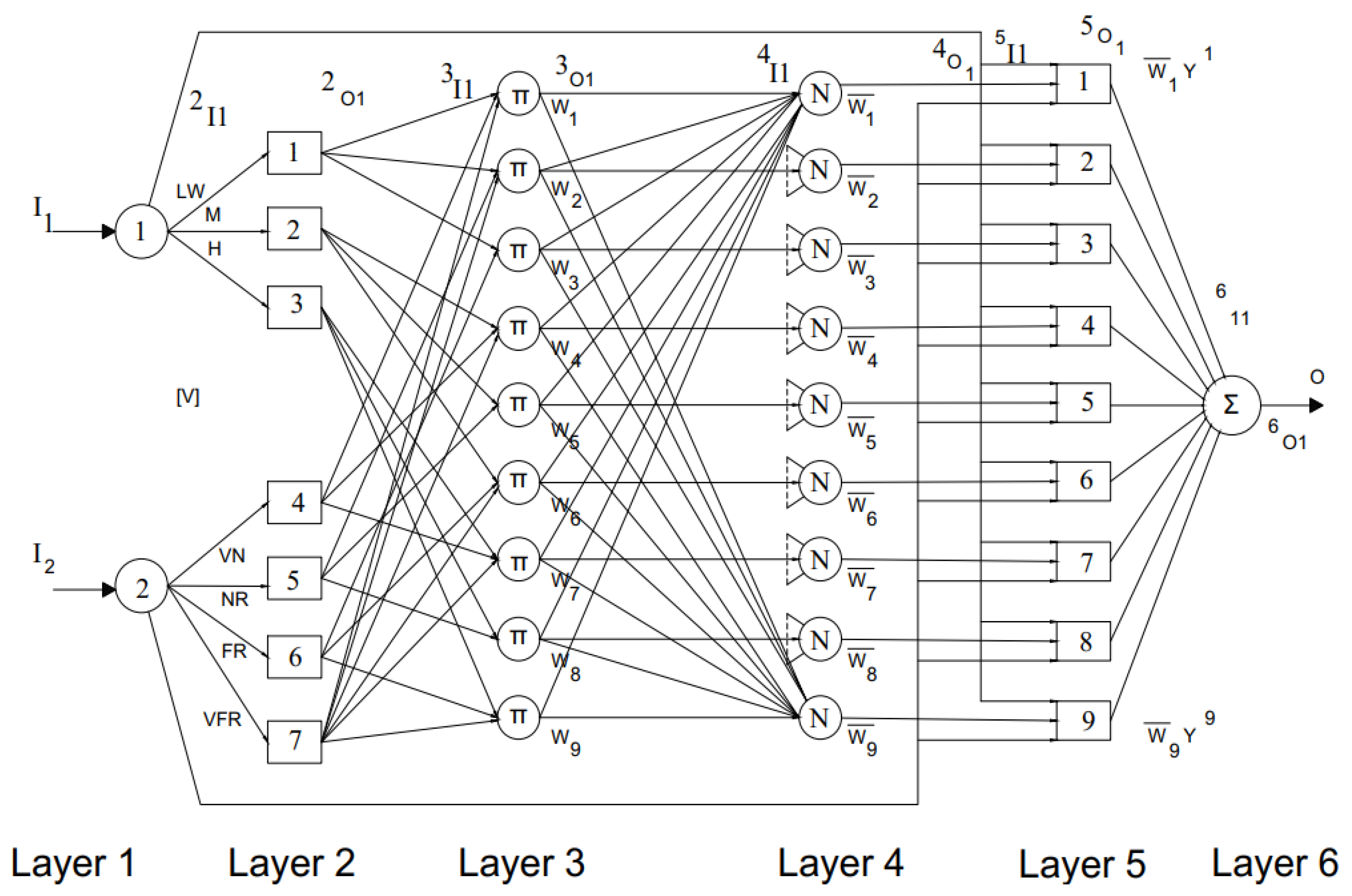
The fuzzy neural system uses the learning algorithm of a multi-layer neural network to adjust the parameters and structure of the fuzzy set (
Figure 5 and
Figure 6). This means that the fuzzy set can construct itself (without needing specialized knowledge of the object it models) when given a rich data set. The finished structure can easily be “compiled” into a human-friendly legal language. This is an effective combination of soft computing technology.
The neural network simulates the processing of a fuzzy system in which the neurons of the first layer are responsible for the fuzzification process. The neurons of the second layer represent the fuzzy words used in the fuzzy rules (third layer). Finally, the neurons of the last layer are responsible for the defuzzification process. In this sense, the training of this neural network results in automatically adjusting the parameters of a fuzzy system and finding their optimal values.
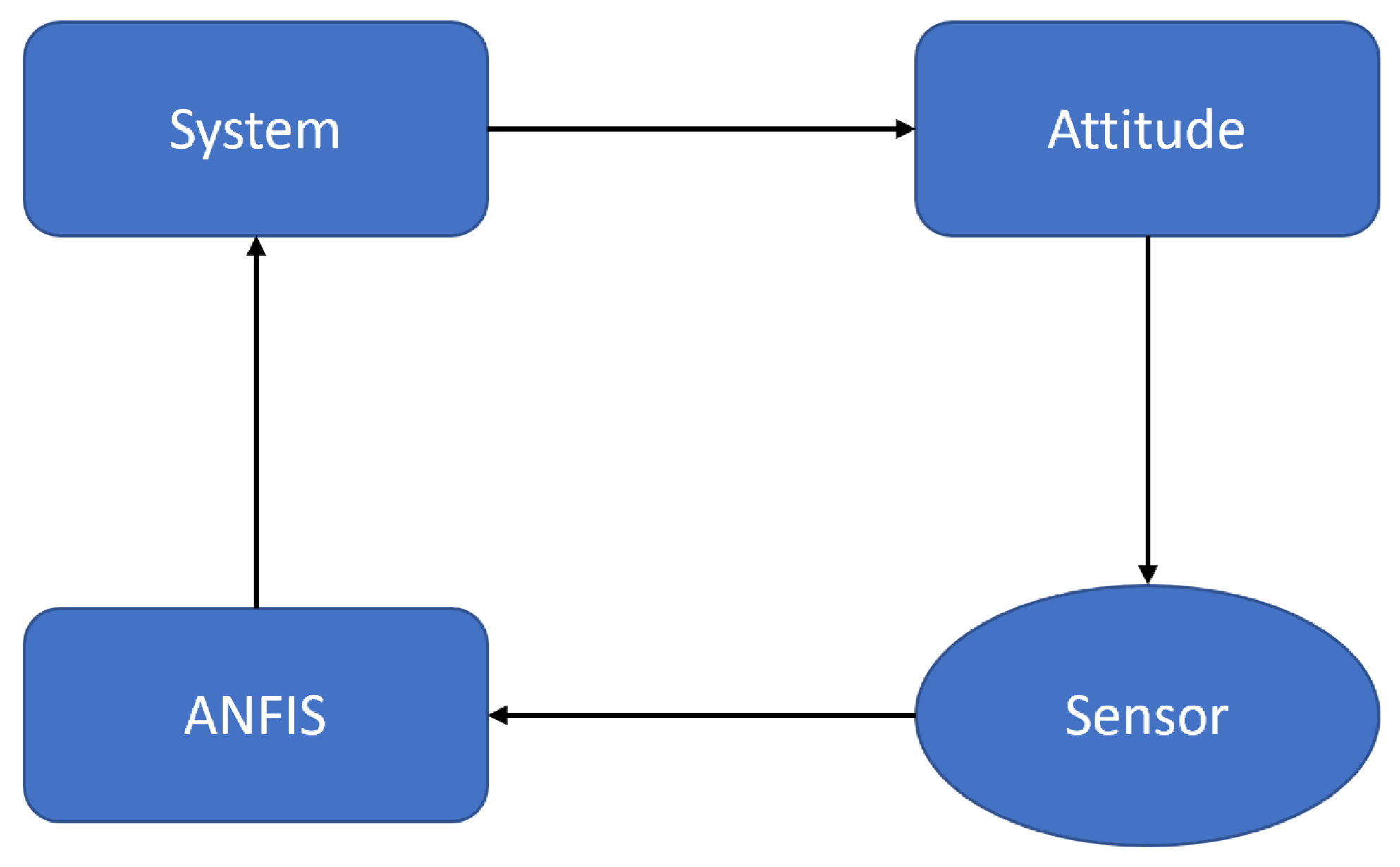
Figure 7 explains the connection of the ANFIS controller to the sensors and the system to control the rescue drone at sea.
3. Drone Controller Scheme
3.1. Position Controller and Altitude Controller of Marine Rescue Drone
- −
6 degrees of freedom: X, Y, Z, roll, pitch, yaw
- −
4 control inputs: for thrust, , , for torque on axis.
is the angular speed of the four motors.
g: Gravity acceleration.
b: Thrust coefficient.
The symbol for the sum of all external forces acting on the plane is:
with components Fx, Fy, Fz defined by the body coordinate system.
According to Newton’s 2nd law we have:
With = (u, v, w) is the absolute velocity vector of the plane in terms of the body coordinate system.
The equations describing the horizontal motion of the Quadrotor:
Due to the suspended state, the roll torque
, so we have:
So, the state space model describing the horizontal motion of the plane is:
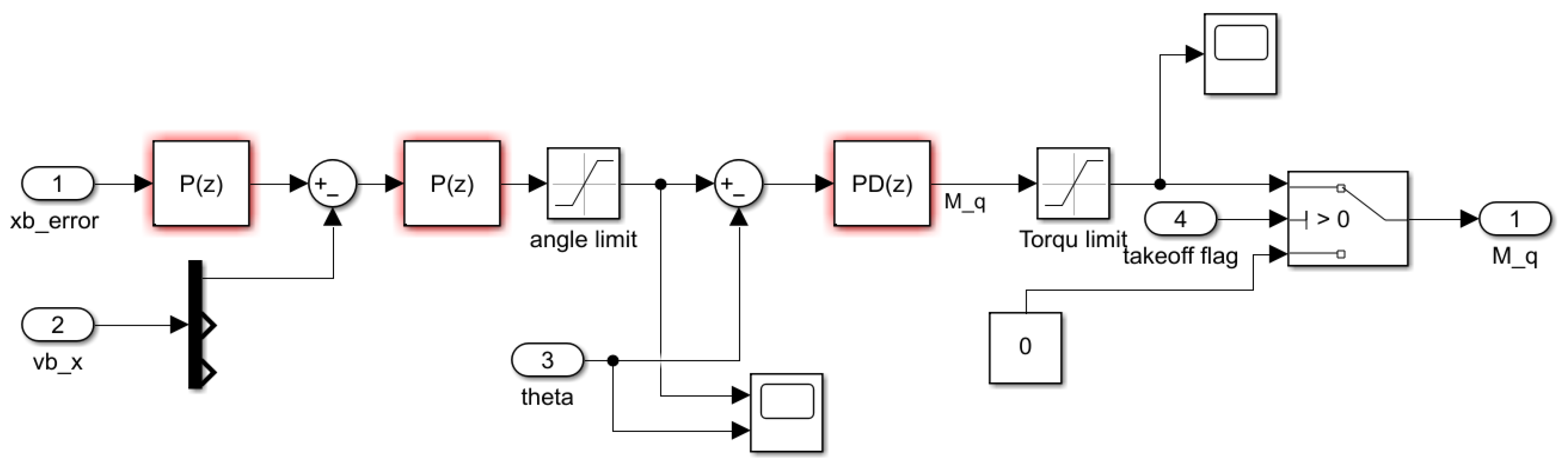
From the above formula, the transfer function is obtained, thereby simulating the stable controller X shown in
Figure 8.
- −
The equations describing the vertical motion of the Quadrotor:
Due to suspended flight, pitch moment
, we have:
So, the state space model describing the horizontal motion of the plane is:
From the above formula, the transfer function is obtained, thereby simulating the stable controller Y shown in
Figure 9.
The equations describing the translational motion in the
axis of the Quadrotor:
According to small noise theory, we can ignore higher order small noise quantities larger than 1:
Since the thrust in the suspended state of the engines is:
So, the state space model describing the horizontal motion of the plane is:
From the space state models infer:
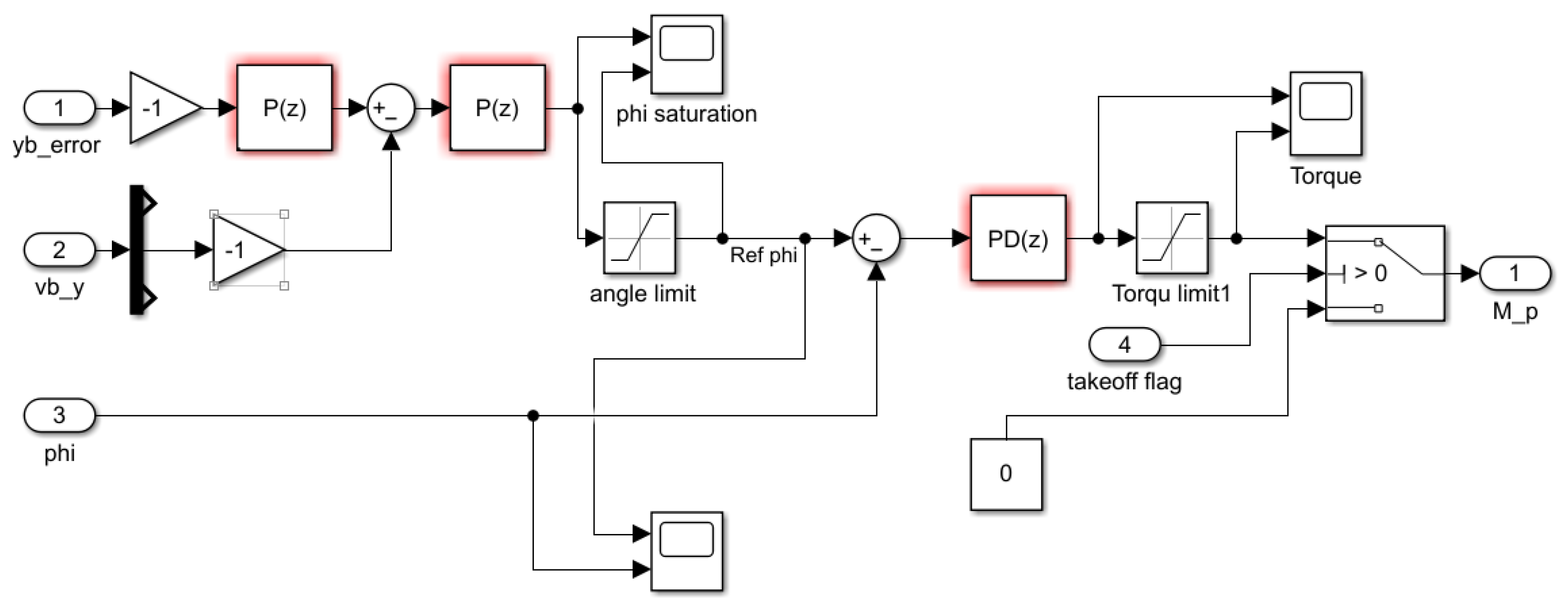
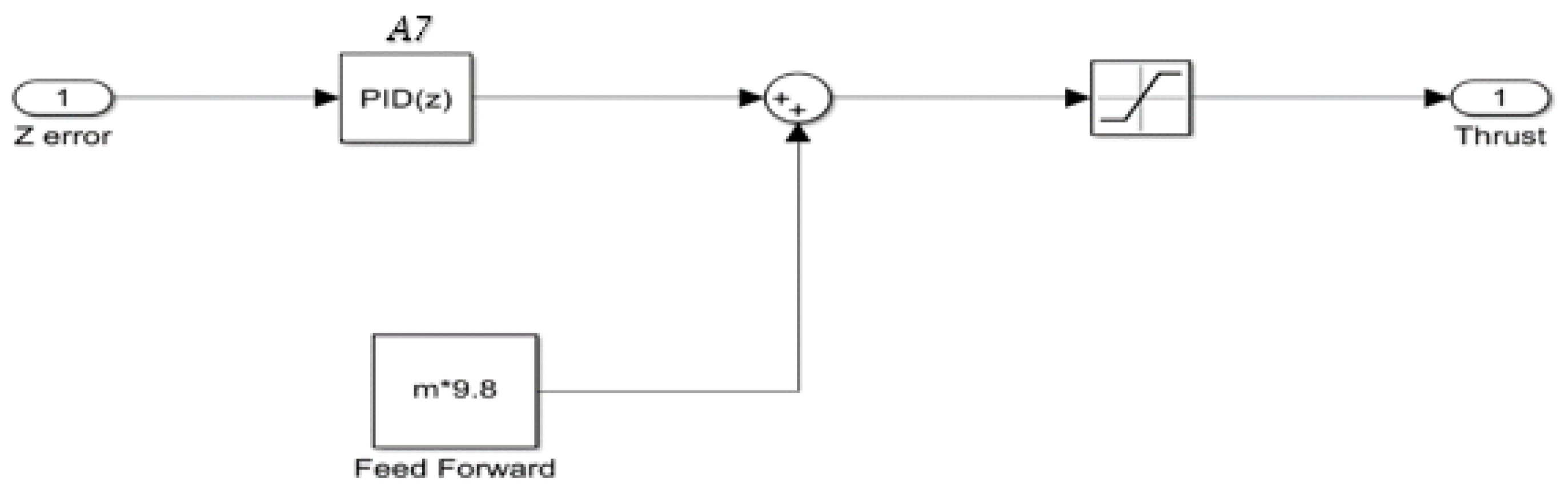
The Altitude Control is the PD Controller then the Mass Resume block combines to control the altitude.
Position control consists of a circular cascaded PD loop where the outer PD control loop generates a signal output signal to the inner corner PD control loop.
From the above formula, the transfer function is obtained, thereby simulating the stable controller Z shown in
Figure 10.
3.2. Disturbance Signal
This simulation models wind turbulence. The goal is to add real-world effects. Using the concept in this model, users can further model other real-world terms, such as noise sensors and motor output fluctuations.
Turbulence is written in the [Force and Environment/Turbulence] block. Wind Level, Noise Level, and Wind Sampling Time are editable to see how the drone performs in different conditions.
In the general case, the wind speed vector W is a very complex function of space and time:
The wind speed vector in the general case can have an arbitrary direction in space, so it is possible to analyze the components W, W, W (according to the ground coordinate system O). The components themselves are also spatially and temporally dependent.
The wind simulation varies at various levels [
25] below as shown below, Algorithm 1. is algorithm for Wind setting using Matlab/Simulink:
| Algorithm 1: Wind setting algorithm |
% Disturbance Signal
ts = 0.01;
WindLevel = [10];
WindSpeed = [13244]; |
In the Wind algorithm is the set WindLevel = [x] and WinSpeed = [y] where x, y are any 2 values that are suitable for the problem. It can be customized according to actual requirements.
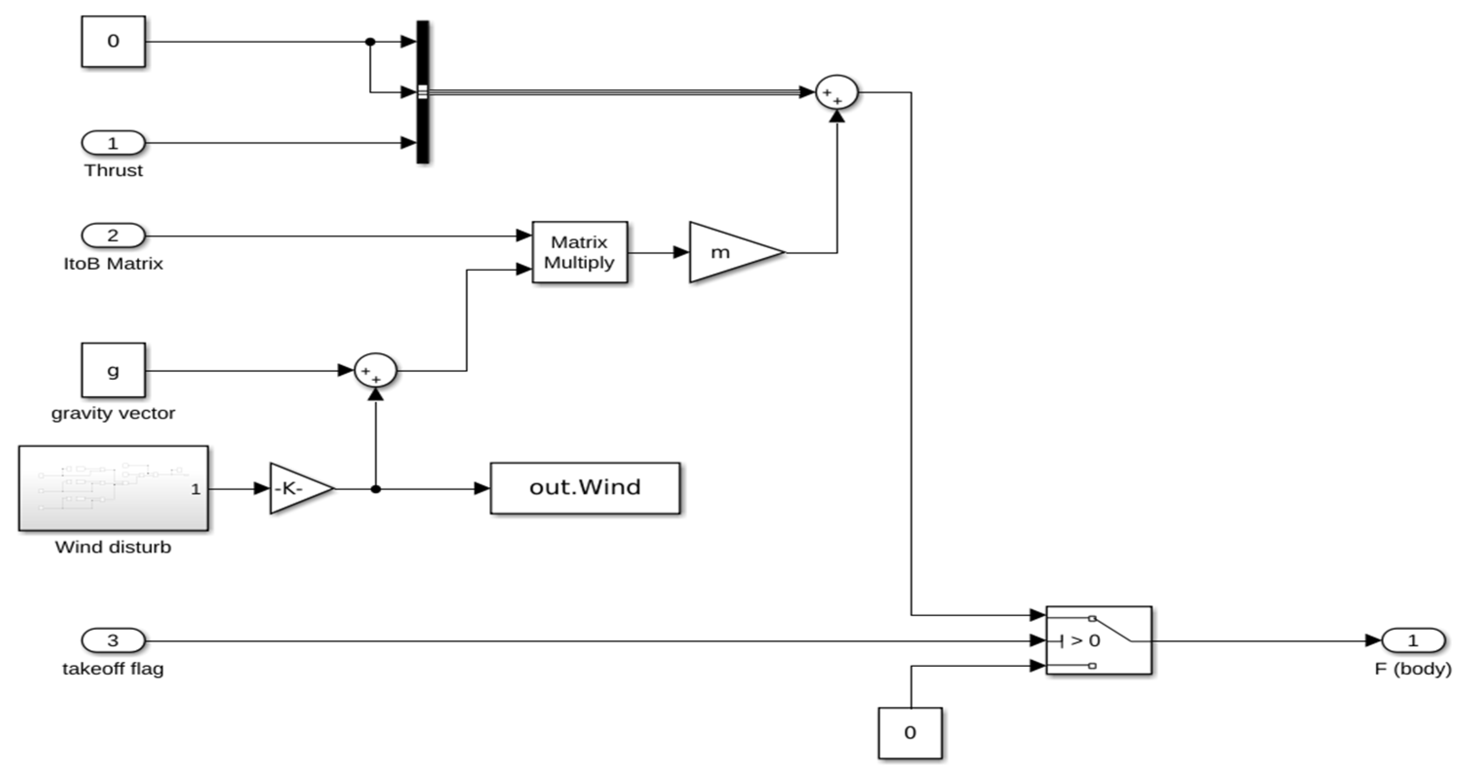
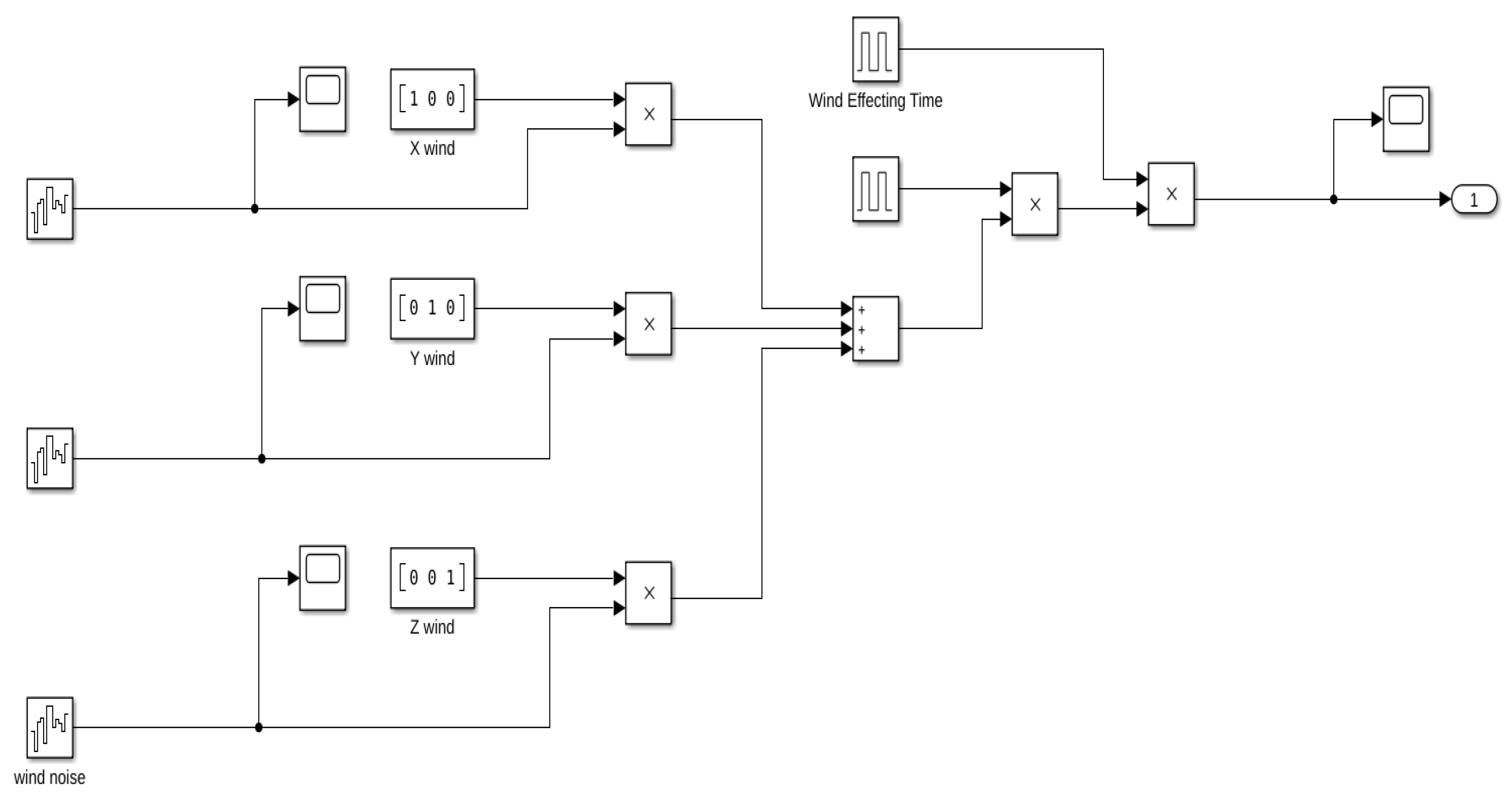
Figure 11 and
Figure 12 show simulation of the forces and noise signals acting on the Drone.
Inside Force and Environment subsystem:
Inside Wind Disturb block:
3.3. Algorithm Neural Network–Fuzzy Controller
In this study, the proposed neural-fuzzy controller is a neural-fuzzy system based on Takagi and Sugeno’s Approach. It is also an Adaptive Neuro-Fuzzy Inference System (ANFIS) [
25,
26,
27,
28,
29,
30,
31]. The proposed controller has two inputs:
and
and one output: O. Membership function distributions of input and output variables of the controller to be output are shown in
Figure 13.
The Neural-Fuzzy controller has 7 values of the fuzzy set that are related according to the
Table 2.
According to first-order Takagi-Sugeno’s model of Fuzzy Logic Control:
where,
I = 1,2,….
are coefficients.
Figure 14 shows a diagram of the relationship between the classes of the ANFIS layer.
Following 4 rules are fired, corresponding to a set input
and
:
Layer 1:
Linear TF (output = input)
Layer 2:
Fuzzification (µ)
Layer 3:
Firing strengths of the rules are calculated considering the products of µ values:
Layer 4:
Calculate normalized firing strength of each rule:
Layer 5:
Output is calculated as the product of normalized firing strength and output of the corresponding fired rule y
Layer 6:
The error loss function E is given by:
where:
is the actual output value
is the desired output value
Algorithm 2. is algorithm for ANFIS controller using Matlab/Simulink.
| Algorithm 2: Neural-Fuzzy controller setting algorithm |
fis = anfis(Drone_NF_ControllerData);
numObs = 3;
opt = anfisOptions(‘InitialFIS’,6,’EpochNumber’,40);
[trainFIS,trainFISError,~,validationFIS,validationFISError] = anfis(NFControllerData,opt);
observationInfo = rlNumericSpec([numObs 1]);
observationInfo.Name = ‘observations’;
numAct = 1;
actionInfo = rlNumericSpec([numAct 1]);
actionInfo.LowerLimit = −1;
actionInfo.UpperLimit = 1;
actionInfo.Name = ‘Control’;
actionInfo.Description = ‘Thurst’;
mdl = ‘Drone_NF_Controller’;
load_system(mdl);
blk = [mdl,’/RL Data’]; |
3.4. Model of Neural Network–Fuzzy Logic Controller in Matlab/Simulink
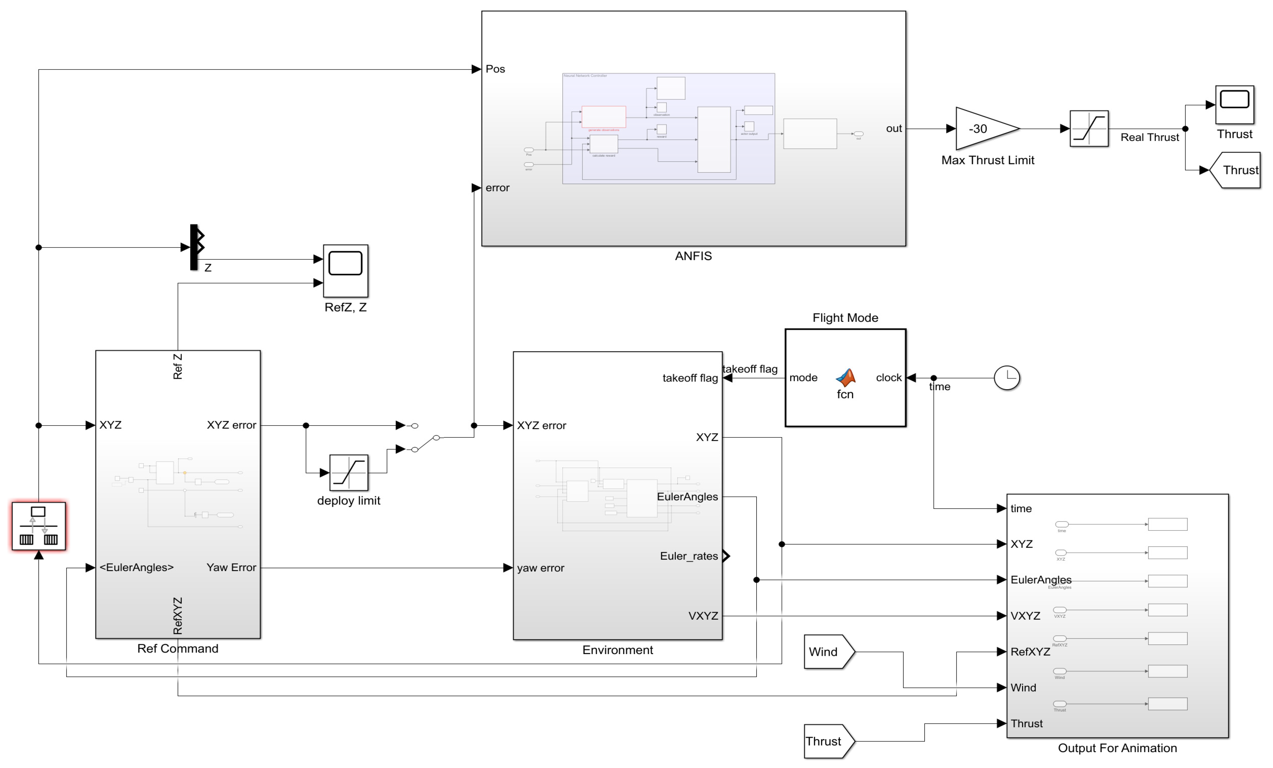
Figure 15 simulates the Neural-Fuzzy controller [
26,
32,
33] on Matlab/Simulink. Including environmental blocks (interference force of the impacting environment, control block, and simulation of 6DoF coordinate system mentioned in
Section 2.1) and Neural-Fuzzy system(ANFIS), Ref command.
4. Results and Discussion
The input parameters used in the simulation are shown in
Table 3 and
Table 4.
Using the manual method is performed many times testing many times, and the Tunning method of Matlab/Simulink obtains the PD coefficients of the PID controller.
The experiment was performed several times with different noise parameters and obtained the same results. There are different levels of wind, and the Drone can only work stably with a wind level below 10. At level 10 there is already but deviation in motion. When at level 11, the Drones cannot work stably. Below are the results obtained showing the features of the Neural-Fuzzy controller. Simulation on Matlab obtained the following results:
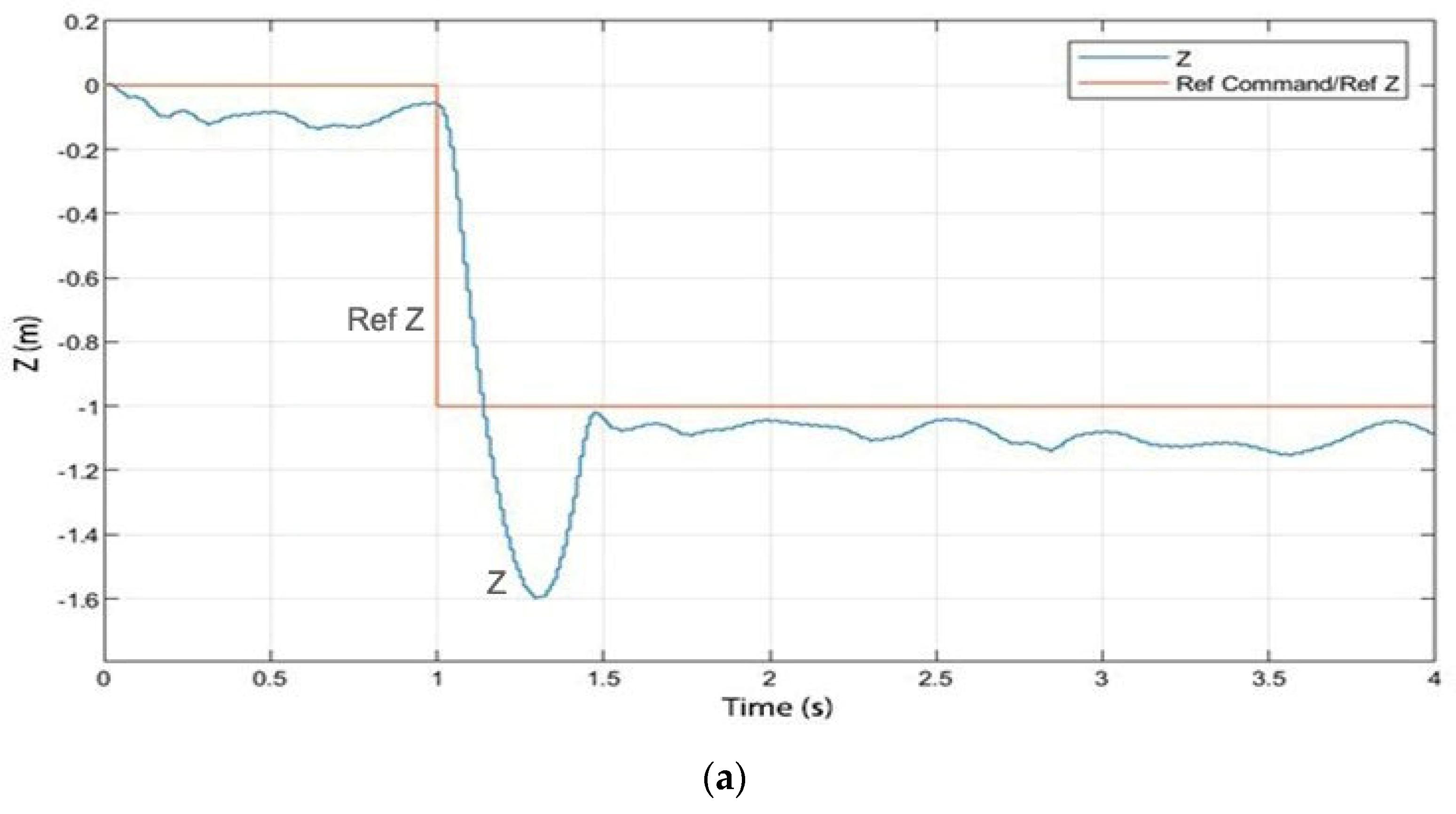
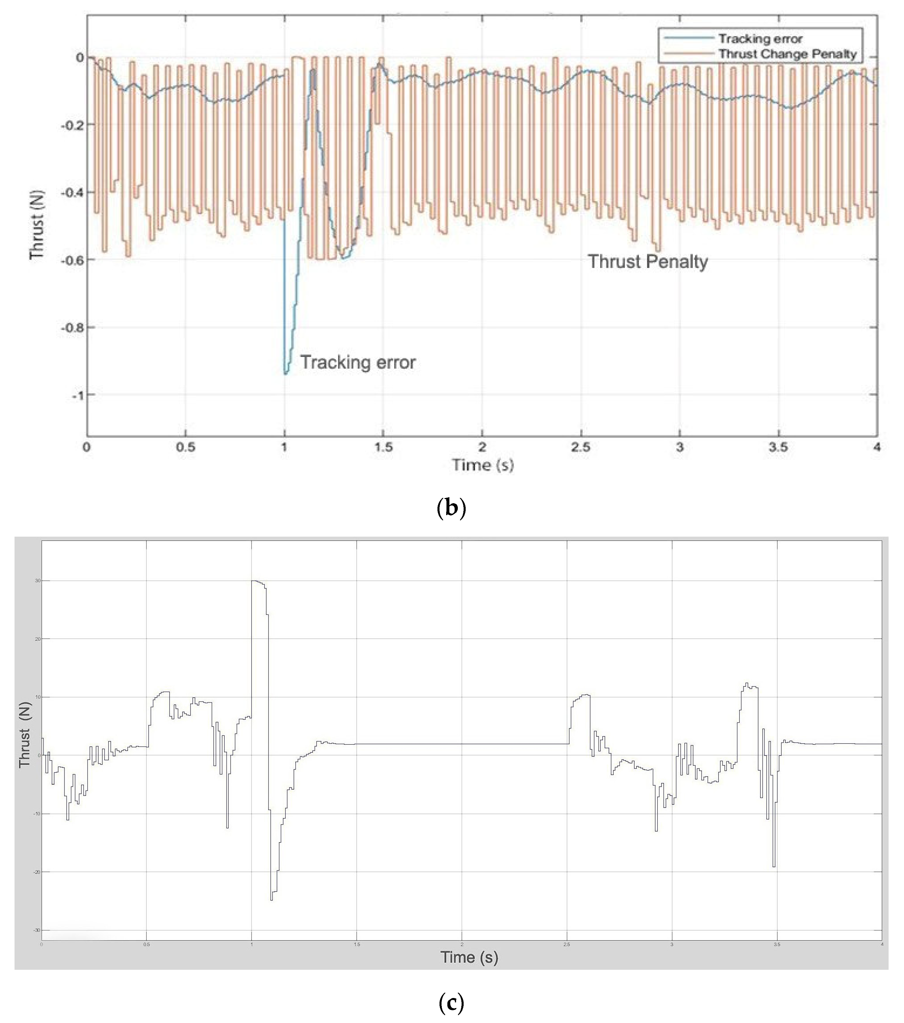
Figure 16 shows that signal Z is always selling close to the given set signal and Thrust’s quick response to a tracking error signal. This shows the responsiveness of the controller so that operations are more accurate than expected.
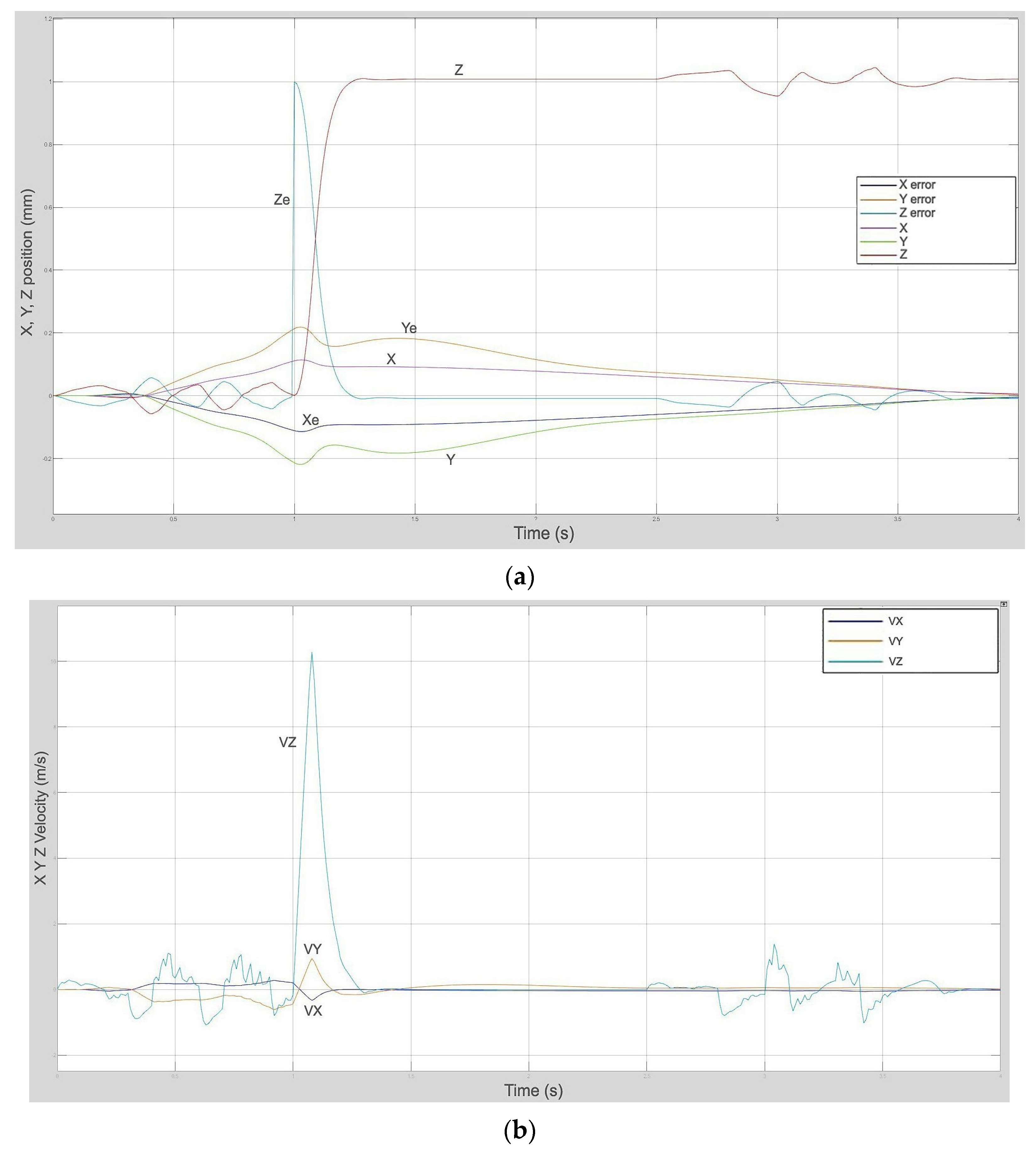
Figure 17 shows the change of parameters position xyz as well as velocity Vxyz to reduce the error signal to zero. The first second due to noise oscillation makes the operation stable, and the error signal reaches the highest amplitude where the values are learned and adjusted for the error signals and bring them to zero at time t = 4 s, and can still be interfered with by the impact of the ever-changing and continuous environment. Then the Neural-Fuzzy controller will always update and give a new signal to adjust and bring the error signal to zero to help the rescue drone work stably.
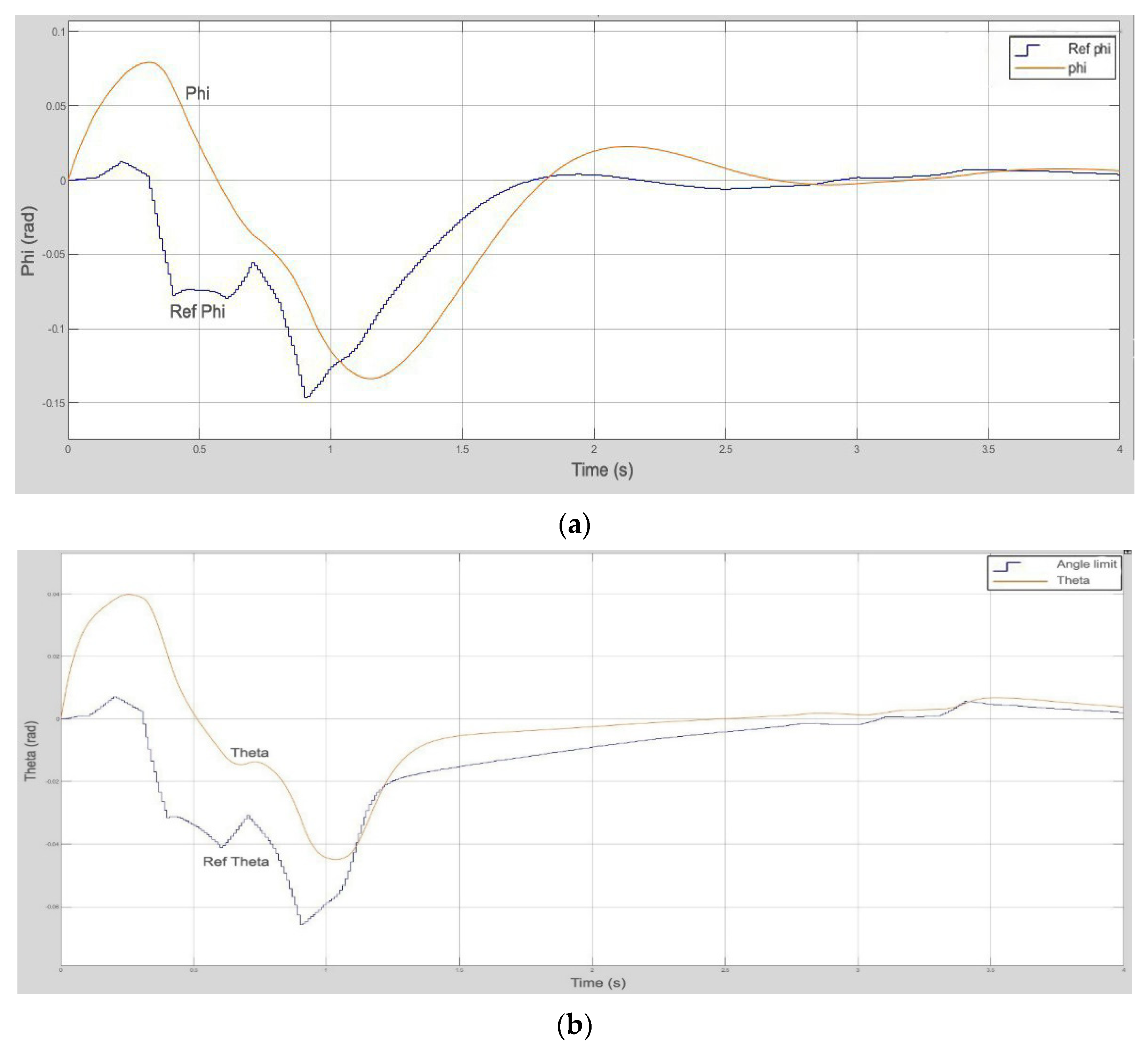
Figure 18 shows that both Theta and Phi can change in a timely manner to closely follow the set signal and increasingly narrow the error gap with the set signal.
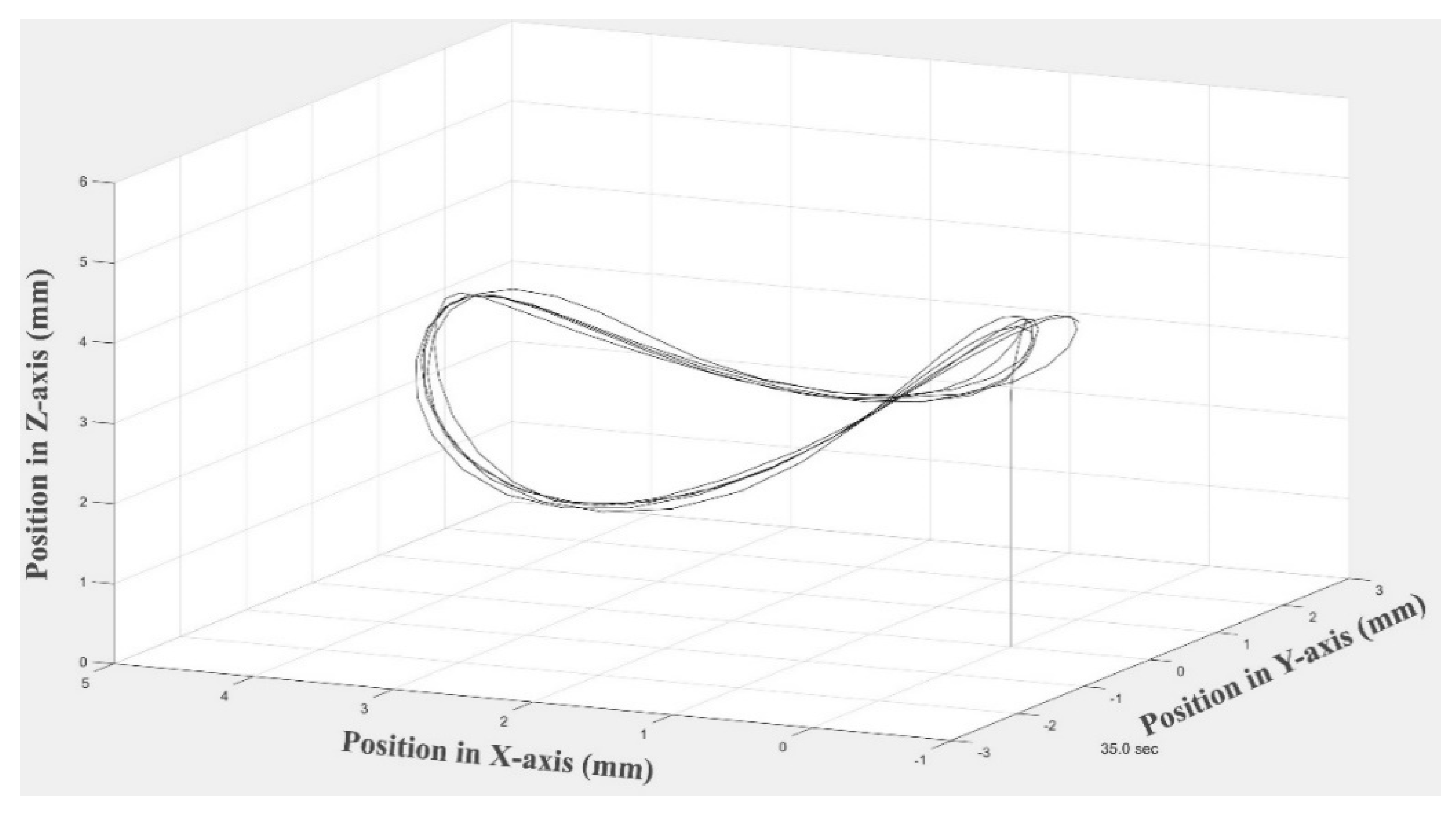
Figure 19 is a simulated image of the drone’s movement on the 3D xyz coordinate system, it can be seen that the orbits are close to each other and have very little deviation, the difference between the two orbits is very small, the two orbits are different each other is approximately 0.3 mm.
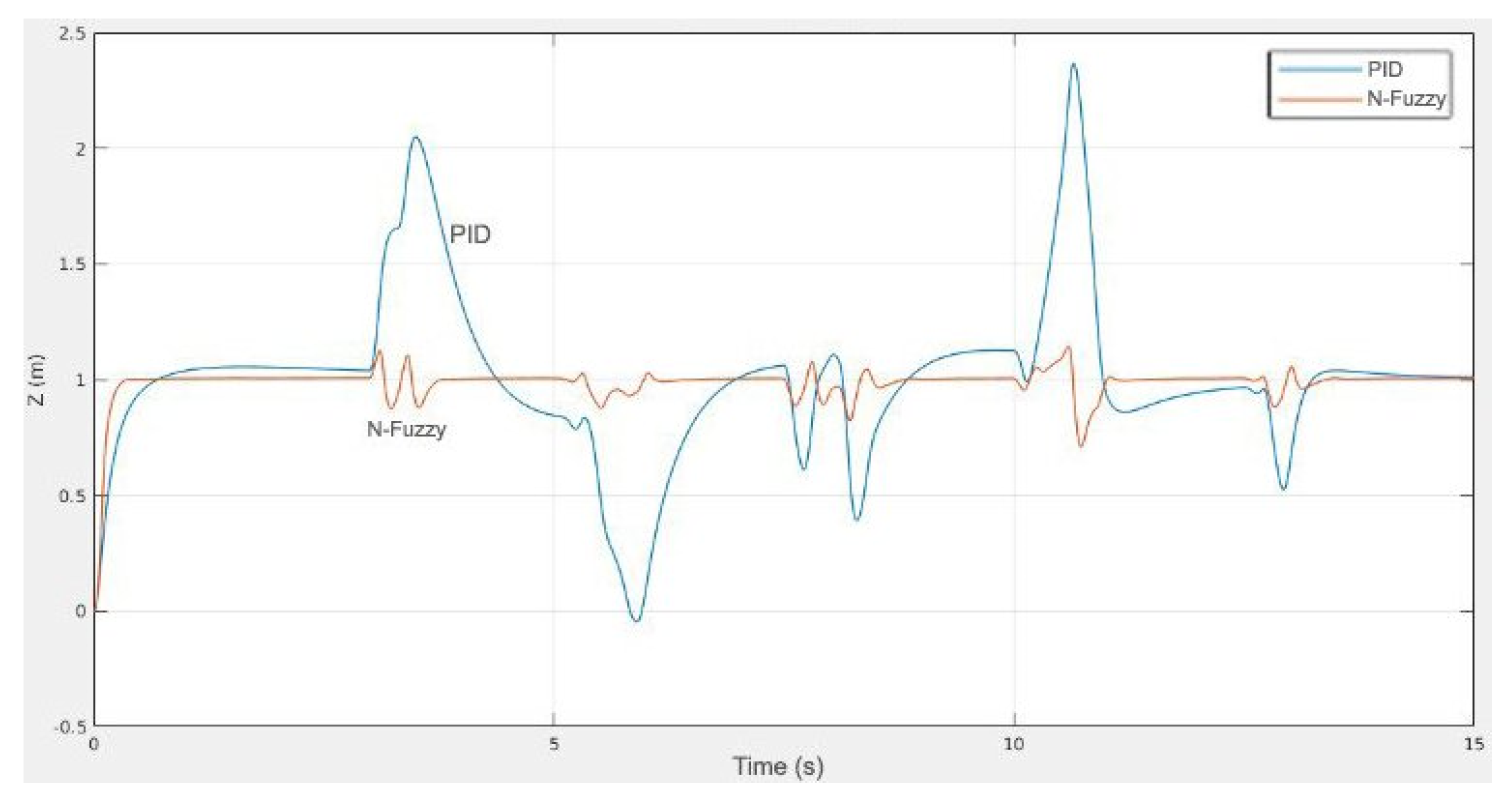
To verify how to evaluate the difference, we use a Neural-Fuzzy controller to control the Z position of the drone. Compare the controller with a classical PID controller under different wind disturbance levels along the z-axis and thrust.
To verify increased accuracy, compare two controllers with noise and no noise conditions to be able to compare and evaluate in the most objective and accurate way.
Where there is no wind:
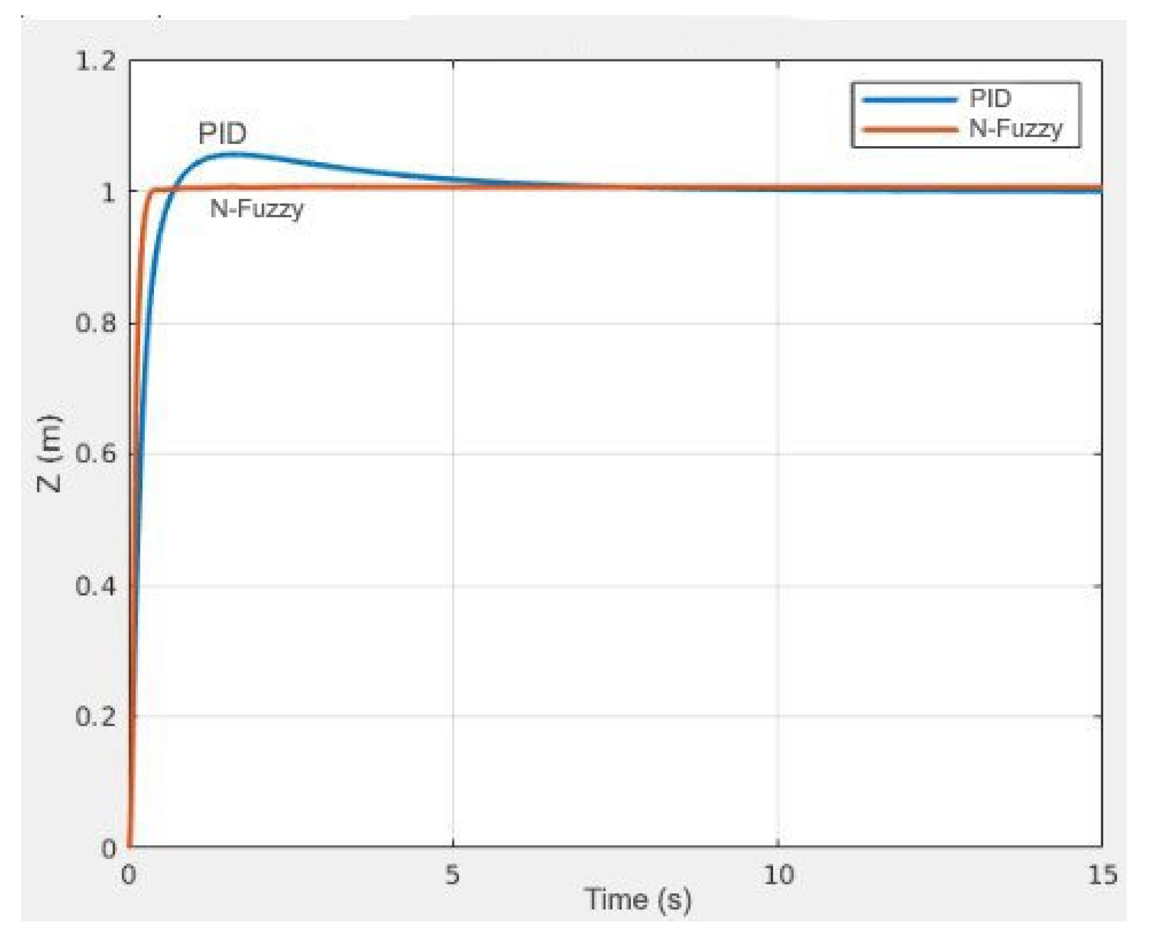
The stability and tracking of the given altitude Z = 1 of the Neural-Fuzzy controller is much higher than that of the classical PID controller. From the above two simulation results (
Figure 20 and
Figure 21), we can see that under the influence of different noise levels, the Neural-Fuzzy controller is more effective.
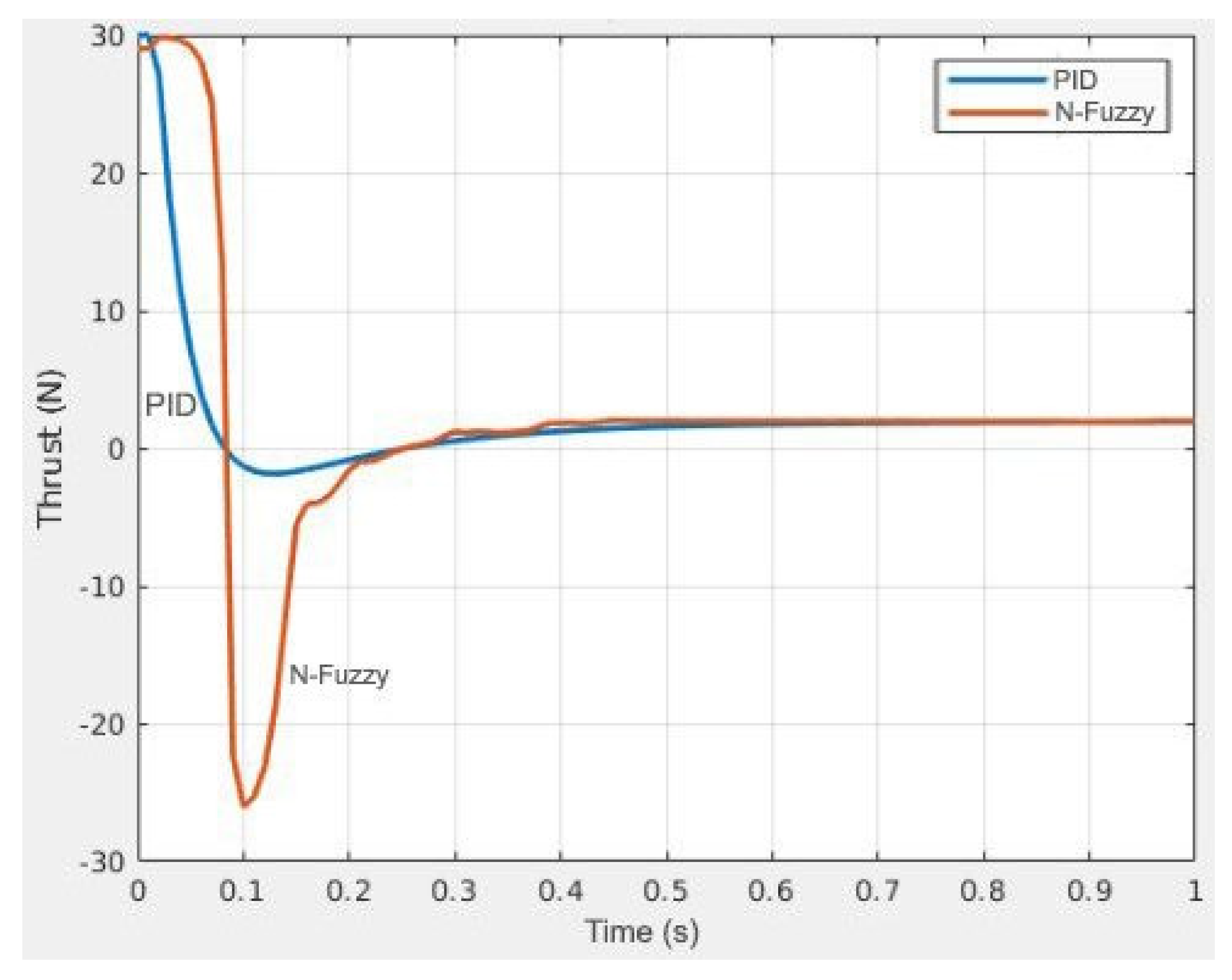
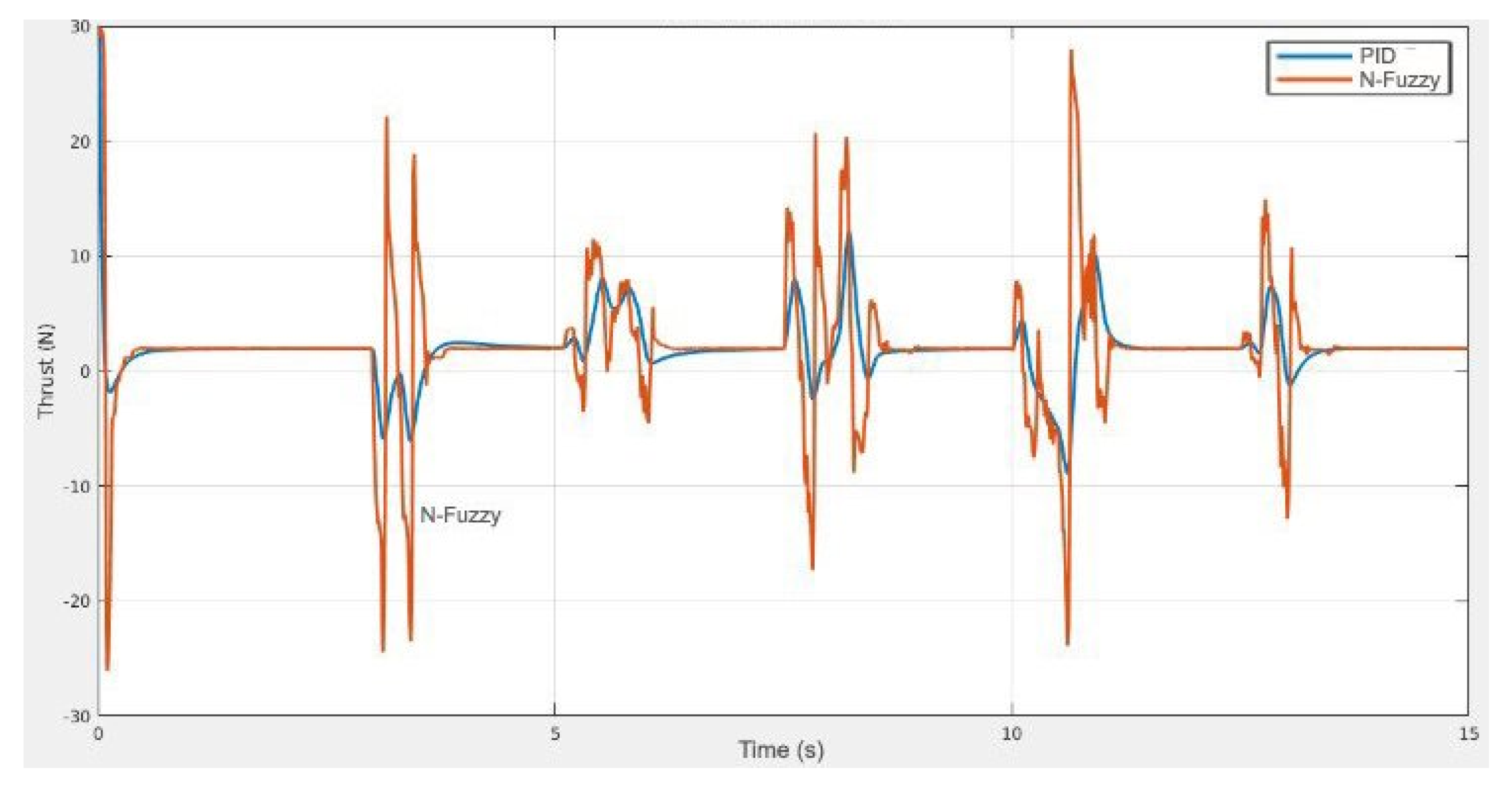
In
Figure 22 and
Figure 23, we can see that the propulsion of the control system by the Neural-Fuzzy hybrid controller is fast, strong, and increases the efficiency to help the navigation of the maritime unmanned rescue aircraft, better than the conventional PID controller. The response of the Neural-Fuzzy controller is much better than that of the PID controller.
It is easy to see that the Neural-Fuzzy controller reaches the steady state of Z very soon (it takes about 0.5 s from the start) with a Thrust force of up to 30 Newtons to quickly adjust the state. As for the PID controller, it takes about 1.5 s to reach a stable state, and the highest Thrust force can only be up to 10 Newtons, making the adjustment against noise to help the Drone stabilize the state for longer than the Neural-Fuzzy controller.
From the obtained results, we can see that the disturbances caused by the environment were quickly overcome thanks to the self-learning feature of the neural network and the inference of the fuzzy logic controller for the drone to operate efficiently. fruit. There are some features worth discussing, such as:
How to create a reward function so that this composite controller can learn just like what we want it to do. It is noticed that one of the advantages of a neural network is that it can learn on its own. However, it is still needed to monitor the training to determine if it “learns the right on path” or not.
Training time and computing resources are enormous. (For this simulation it requires 24 h memory and 6 GB for training).
The generated command output may not be appropriate in real-life cases. (This problem assumes the use of a perfect motor that can perfectly obey the thrust command. To implement the Neural-Fuzzy controller in the real world, it is necessary to model the motor at the same point in time).


