Article

Study on the Hole-Forming Performance and Opening of Mulching Film for a Dibble-Type Transplanting Device

1
State Key Laboratory of North China Crop Improvement and Regulation, Baoding 071001, China
2
College of Mechanical and Electrical Engineering, Hebei Agricultural University, Baoding 071001, China
3
College of Agronomy, Hebei Agricultural University, Baoding 071001, China
*
Author to whom correspondence should be addressed.
Agriculture 2024, 14(3), 494; https://doi.org/10.3390/agriculture14030494
Submission received: 27 January 2024 / Revised: 7 March 2024 / Accepted: 11 March 2024 / Published: 18 March 2024
(This article belongs to the Special Issue Design, Optimization and Analysis of Agricultural Machinery)

Abstract

:
In order to improve the quality of transplanting devices and solve the problems of the poor effect on soil moisture conservation and more weeds easily growing due to the high mulching-film damage rate with an excessive number of hole openings, we developed a dibble-type transplanting device consisting of a dibble-type transplanting unit, a transplanting disc, and a dibble axis. The ADAMS software Adams2020 (64bit) was used to simulate and analyze the kinematic track of the transplanting device. The results of the analysis show that, when the hole opening of the envelope in the longitudinal dimension was the smallest, the transplanting characteristic coefficient was 1.034, the transplanting angle was 95°, and the transplanting frequency had no influence. With the help of the ANSYS WORKBENCH software Ansys19.2 (64bit), an analysis of the process of the formation of an opening in the mulching film and a mechanical simulation of this process were completed. The results indicate that, when the maximum shear stress of the mulching film was the smallest, the transplanting characteristic coefficient was 1.000, the transplanting frequency was 36 plants·min−1, and the transplanting angle was 95°. In addition, the device was tested in a film-breaking experiment on a soil-tank test bench to verify the hole opening in the mulching film. The bench test showed that, when the longitudinal dimension was the smallest, the transplanting characteristic coefficient was 1.034, the transplanting frequency was 36 plants·min−1, and the transplanting angle was 95°. When the lateral dimension was the smallest, the transplanting characteristic coefficient was 1.034, the transplanting frequency was 36 plants·min−1, and the transplanting angle was 90°. The theoretical analysis, kinematic simulation, and soil-tank test results were consistent, verifying the validity and ensuring the feasibility of the transplanting device. This study provides a reference for the development of transplanting devices.

1. Introduction

At present, vegetable seedling transplanting operations are performed either manually or by semi-automatic transplanting machines. Manual transplantation on a large commercial scale remains labor-intensive and time-consuming and has high operating costs and low work efficiency [1,2]. This places a serious restriction on the large-scale industrialization of vegetables. However, mulching-film transplanting machines can effectively cut costs, improve the transplanting efficiency, and provide economic benefits [3,4,5,6,7]. However, the high mulching-film damage rate with an excessive number of hole openings can result in poor soil moisture retention and more weed growth, which have become common problems for dibble-type transplanters. As the most important part of the transplanting machine, the transplanting device has a direct impact on the hole-forming performance and transplant quality of the transplanting machine. Thus, the transplanting device also affects the survival rate of vegetable seedlings.
Research on improving the transplant quality and optimizing performance has attracted more and more attention from scholars. Hu et al. [8] designed a new automatic transplanting mechanism based on a clamping stem. Quan et al. [9] proposed a scheme for eliminating the forward speed of the entire machine by the horizontal linear velocity of the reverse rotation of the hole-forming mechanism. Vlahidis et al. [10] evaluated the functional parameters of a prototype single-row seedling transplanter. Fu et al. [11] simulated and performed an experiment on the compression molding behavior of a substrate block suitable for mechanical transplanting based on the Discrete Element Method (DEM). Du et al. [12] designed a mathematical model, based on the movement trajectory formula of a dibble-type transplanting device, that considers the planting depth, zero-speed transplanting, and the smallest amount of mulching-film damage in order to solve the mulching-film damage problem. Feng et al. [13] proposed design criteria for a dibble-type transplanting device and obtained the constraint formulas for the zero-speed-transplanting throwing conditions and the minimum-film-breaking conditions of a dibble-type transplanter through a theoretical analysis. Cui et al. [14] optimized the movement trajectory of a dibble-type transplanting device and found that the best position for planting seedings is the rising stage of the planting devices after reaching the lowest point, and plant spacing can be changed by changing the transmission ratio or the number of planting devices. The above-mentioned scholars have studied the hole-opening dimension of the transplanter. In terms of the kinematic trajectory, Li and Liu et al. [15,16] reduced the degree of tearing in the mulching film by optimizing the dimensions and kinematic parameters of a dibble-type transplanting device. Tian and Zhang et al. [17,18] analyzed the laws governing the opening of the duckbill of a dibble-type transplanter based on Pro/E and obtained the displacement–time characteristic curve of the motion of the transplanter. Jin et al. [19] designed a duckbill-type pot transplanter to solve the problem of the easy tearing of the mulching film by the dibble-type transplanter and determined the influence of the main parameters on the transplanting track based on ADAMS. Xue et al. [20] optimized a fully automated potted cotton seedling transplanting device. The authors found that, during the planting process, the absolute trajectory of the transplanter must maintain an approximately vertical posture at both the entry and excavation stages. Li et al. [21] studied a kind of automatic pick-up device for chili plug seedlings and found that the relative trajectories of the seedling needle and end-point were consistent with the theoretical ones. Zhou et al. [22,23] designed and improved an end effector of a transplanting device to reduce the seedling-carrying phenomenon of flower plug seedlings. Nevertheless, few studies have conducted a film-breaking experiment on a dibble-type transplanting device.
In this study, we fully considered the agronomic requirements of zero-speed transplanting and the minimum damage to the mulching film and the influence of the transplanting characteristic coefficient, the transplanting frequency, and the transplanting angle on the size of the hole openings in the mulching film based on an ADAMS2020 (64bit) (MSC Software, Inc., Newport Beach, CA, USA)kinematic track analysis and an ANSYS19.2 (64bit) WORKBENCH (ANSYS, Inc., New Castle, DE, USA) dynamic simulation. We also carried out a film-breaking experiment on a soil-tank test bench to verify the simulation analysis results and determine the optimal operating parameters. The optimal operating parameters of the transplanting machine can minimize the hole opening in the mulching film so as to achieve moisture preservation and weed control, improve the survival rate of vegetable seedlings, and improve the quality of transplanting operations, which is of great significance for the large-scale production and industrialization of vegetables in China.

2. Materials and Methods

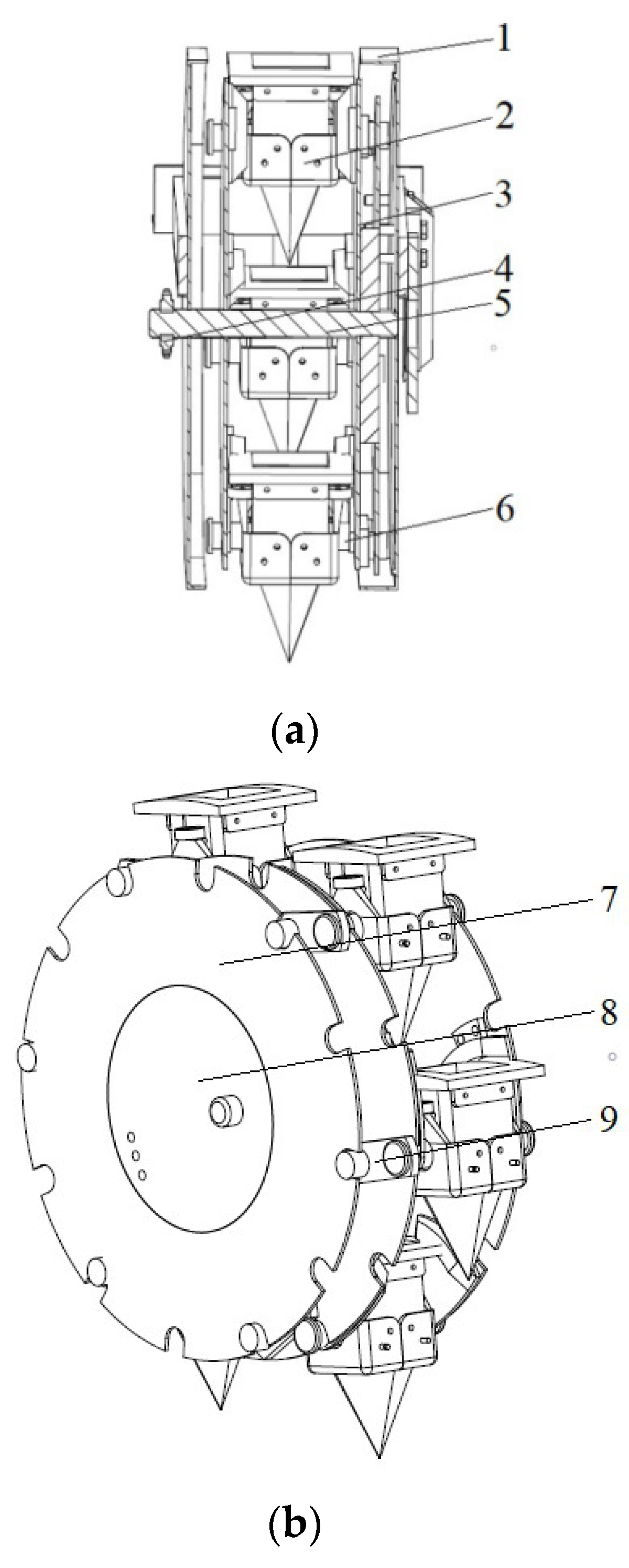
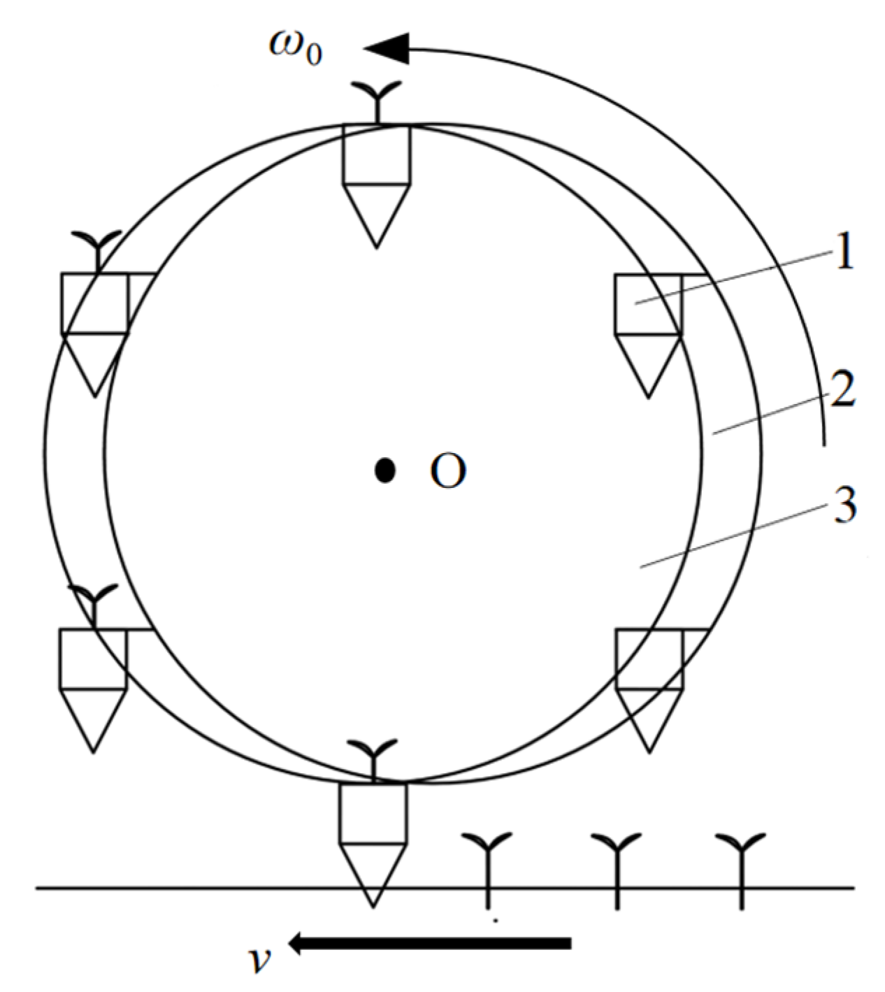
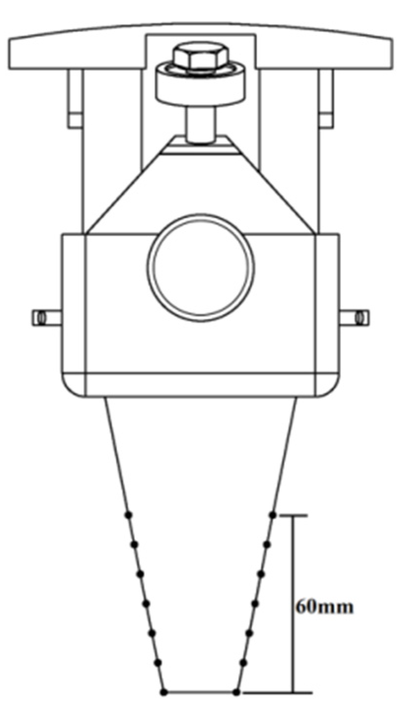
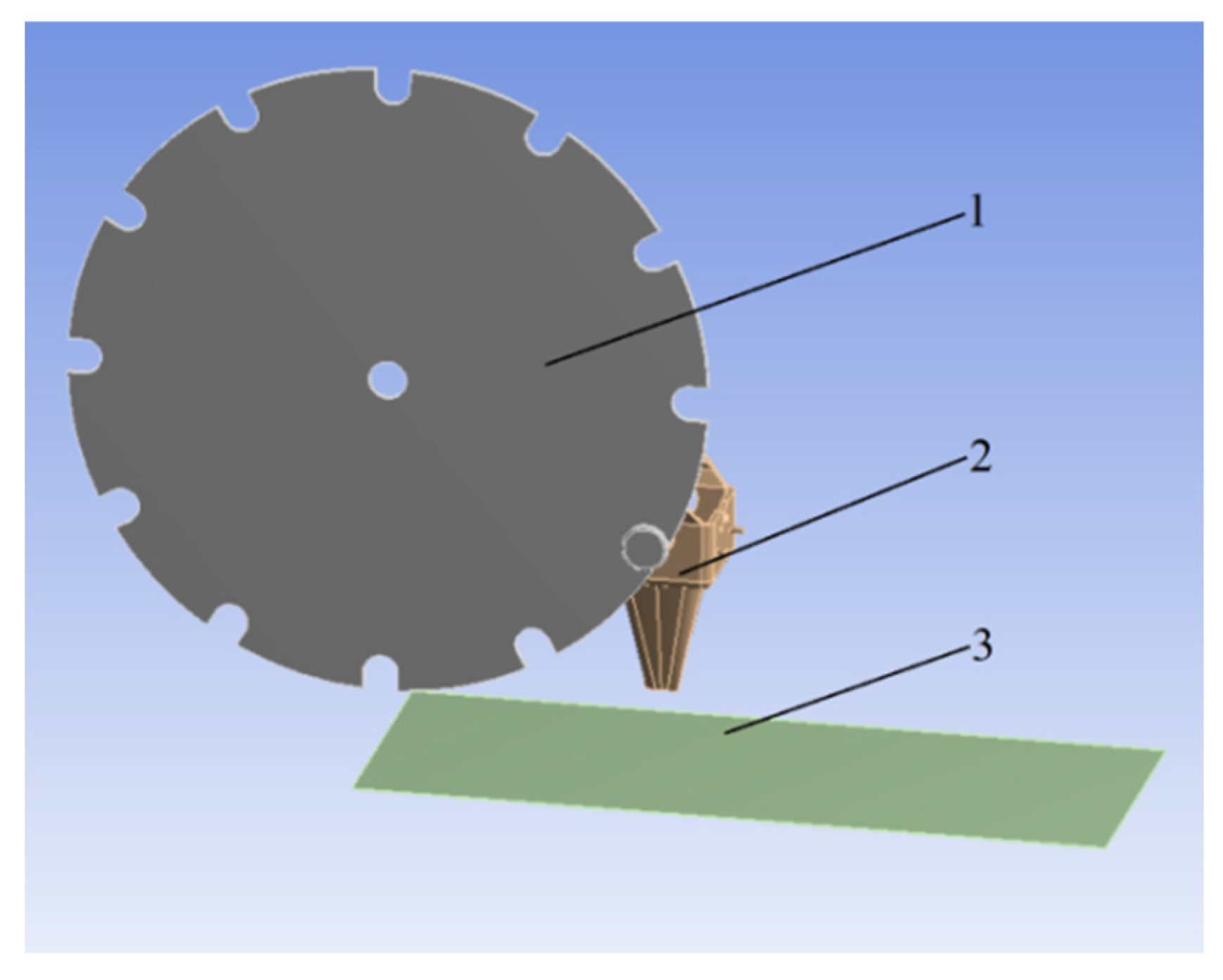
2.1. The Whole Structure and Working Principle of the Transplanting Device

The prototype of the transplanting device is composed of a shell, 6 dibble-type transplanting units, 2 transplanting discs, a sprocket, a spindle, 6 dibble axes, 2 eccentric discs, an eccentric axis, and eccentric connections, as shown in Figure 1.
Each transplanting device is installed with 6 transplanting units. Each transplanting unit is evenly mounted between the transplanting discs by means of a dibble axis. The transplanting discs are power discs. Driven by the transplanting disc, the transplanting units rotate around the center of the transplanting discs. The eccentric discs are mounted on the outside of the transplanting discs by the eccentric axes and are connected to the transplanting discs by the eccentric connections. Under the combined action of the transplanting discs and the eccentric discs, the working angles of the transplanting units remain the same, as shown in Figure 1b.
When the transplanter is operating in the field, the transplanting discs are driven by a ground wheel. The 6 transplanting units rotate with the transplanting disc in the direction of the tractor. A vegetable seedling is manually or automatically fed into the topmost transplanting unit. Under the combined action of the transplanting discs and the eccentric discs, the angle between the transplanting unit with the vegetable seedling and the ground remains unchanged. When it moves to the lower end, it breaks through the mulching film, inserts into the soil, and then opens the dibble under the action of the eccentric discs (equivalent to a cam mechanism), and the vegetable seedling naturally falls into the seedling-hole in the ground under its own weight, followed by soil covering and suppression. The above-mentioned steps form the entire transplanting process of the transplanting device shown in Figure 2.

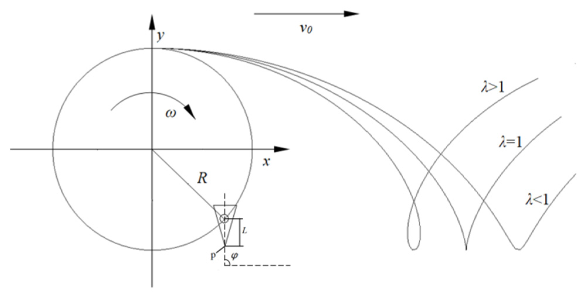
2.2. The Kinematic Analysis of the Transplanting Device

While the transplanting unit moves in a straight line along the direction of travel of the transplanter (Figure 3), the transplanting unit moves in a circular motion along the circumference of the transplanting disc on the transplanting device. The transplanting angle φ is between the center axis of the transplanting device and the direction of the forward speed.
The coordinate system is established with the center of the transplanting disc at the initial position as the coordinate system origin. And then, the kinematic equation for the lower end-point p of the transplanting unit is established, as shown in Equation (1).
{ x = v 0 t + R cos ω t y = R sin ω t L
where v 0 is the forward speed for the transplanting device, m·s−1; R is the rotation radius of the transplanting unit, m; ω is the rotation angular velocity for the transplanting unit, rad·s−1; t is the transplanting time, s; and L is the distance from the center of the transplanting device to the lower end-point P, m.
The first-order derivation of Equation (1) is carried out to obtain the kinematic velocity equation of the lower end-point P of the transplanting unit.
{ v x = v 0 R ω sin ω t v y = R ω cos ω t
The kinematic track of the transplanting unit is mainly related to the transplanting characteristic coefficient λ . λ can be defined by Equation (3):
λ = R ω v 0
The kinematic track of the transplanting unit is greatly affected by λ , as shown in Figure 3. When λ > 1, the kinematic track of the transplanting unit is a trochoid, and the transplanting unit has two points with a horizontal velocity of 0 on both sides of the trochoid loop. When λ = 1, the horizontal velocity v x at the lowest point of the kinematic track is 0. When λ < 1, there is no point where the horizontal velocity is 0 in the kinematic track of the transplanting unit. When the horizontal velocity of the transplanting unit is 0, the vegetable seedling is put in a seedling-hole in the ground, which is conducive to improving the transplanting uprightness of the vegetable seedling. To achieve zero-speed transplanting, a transplanting characteristic coefficient λ ≥ 1 should be ensured. However, when the transplanting characteristic coefficient is too large, the transplanting unit will form a large hole opening in the mulching film, and the problems of mulching-film hanging and mulching-film tearing will occur in severe cases.
The mulching film is close to the ground, and the smaller the hole opening formed in the mulching film when transplanting, the more helpful in preserving moisture. Meanwhile, it can effectively control weeds, which is more conducive to improving the survival rate of vegetable seedlings. The kinematic tracks of the transplanting unit under different transplanting characteristic coefficients λ are shown in Figure 4. The distance H between the mulching film and the bottom of the hole opening is the transplanting depth of the transplanting unit. When the transplanting unit is moved to the lowermost end, the lowermost end-point is at the bottom of the hole opening. The size of the hole opening in the mulching film mainly depends on the horizontal displacement under the mulching film from the lower end-point p from the soil entry point A to the unearthed point B. The horizontal displacement under the mulching film mainly depends on the horizontal displacement l A B formed by the soil entry point A and the unearthed point B and the dimension of l C D at the maximum trochoid loop. The transplanting characteristic coefficient from track 1 to track 5 gradually decreases, and the l A B of track 3 is equal to l C D . It can be seen from Figure 4 that track 3 is a boundary point. With the increase in λ , the displacement l C D of the lower end-point gradually increases. In addition, with the decrease in λ , the displacement under the mulching film formed by the entry point and unearthed point of the lower end-point of the transplanting unit gradually increases. Therefore, when l A B = l C D , the displacement under the mulching film at the lower end-point p of the transplanting unit is the smallest.
When the transplanting unit is moved to the soil entry point A, the height of the lower end-point p from the hole opening is H, and the ordinate y A of the lower end-point p can be defined by Equation (4):
y A = ( R + L ) + H
In Equation (1), θ = ω t , and then θ A is the angle at which the lower end-point P of the dibble-type transplanting unit moves to point A. Then, from Equations (1) and (4), it can be calculated:
θ A = arcsin ( 1 H R )
The rotating radius of the transplanting unit R = 240 mm and the transplanting depth H = 60 mm, so the transplanting angle is calculated as θ A = 0.8481 rad by Equation (5).
According to Equation (1), the abscissa x A of the lower end-point p can be calculated at point A:
x A = 0.8481 v 0 ω + 0.6614 R
When the transplanting unit moves to point C, the horizontal velocity will be equal to 0.
v C x = v 0 ω R sin θ C = 0
Then, the transplanting angle θ C from Equation (7) can be calculated, as shown in Equation (8):
θ C = π arcsin v 0 ω R
Bringing θ C into Equation (1), the x C of the lower end-point p at point C can be calculated by Equation (9):
x C = v 0 ω ( π arcsin v 0 ω R ) + R cos ( π arcsin v 0 ω R )
When xA = xB, Equation (10) can be calculated:
x C x A = 0
Equation (11) is calculated from Equations (3), (6), (9) and (10):
R [ 1 λ ( π arcsin v 0 ω R ) + cos ( π arcsin v 0 ω R ) 0.8484 1 λ 0.6614 ] = 0
From Equation (11), it can be seen that when λ = 1.068, the horizontal displacement of the lower end-point p under the mulching film is the smallest during the hole-forming process for the transplanting unit. The transplanting characteristic coefficient is related not only to the structural parameters of the transplanting device but also to the transplanting depth of the vegetable seedling.

2.3. ADAMS-Based Kinematic Simulation and Analysis for Transplanting Unit

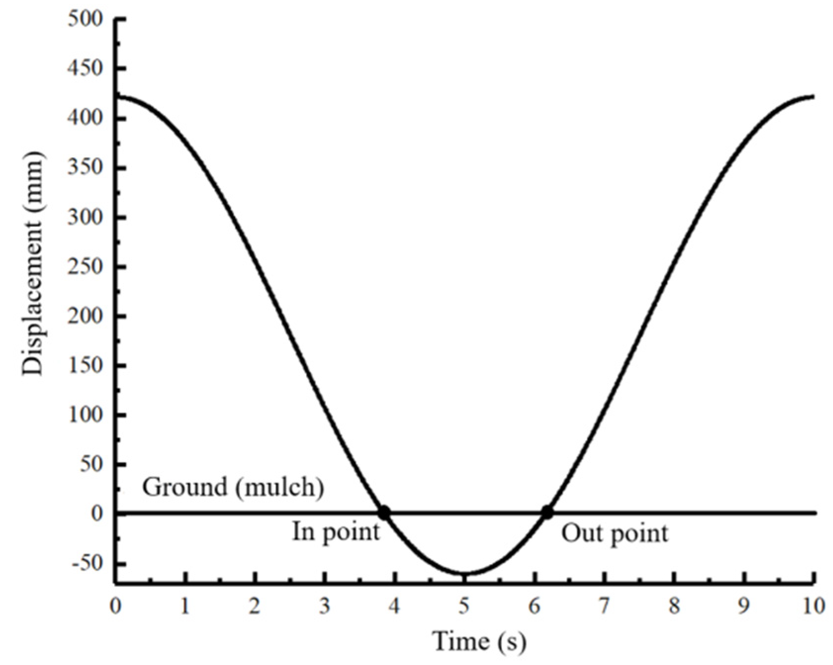
2.3.1. The Displacement Curve of the Transplanting Unit

Equation (1) for the kinematic track of the transplanting unit shows that the displacement y in the vertical direction is only related to the rotational speed ω and is not related to the transplanting characteristic coefficient λ . According to the above, the transplanting characteristic coefficient is selected to be λ = 1.068, and the transplanting frequency is 36 plants·min−1 according to the actual artificial transplanting speed. At this transplanting frequency, the operator has enough time to place the vegetable seedling in the dibble. The kinematic simulation of the transplanting unit was carried out using ADAMS, as shown in Figure 5. The displacement curve coordinates of the lower end-point in the vertical direction were calculated by the ADAMS post-processing module, and the curve coordinates were imported into ORIGIN2021 (64bit) (OriginLab, Inc., Northampton, MA, USA) to generate the vertical displacement curve of the lower end-point. The lowest point of the displacement of the lower end-point for the transplanting unit is the bottom of the hole opening; the ground is 60 mm away from the bottom of the hole opening, and the ordinate of the ground is 0. The two points where the kinematic track intersects with the ground are the soil entry point and the unearthed point, respectively, and then we can calculate that the operation time for the mulching film at the lower end-point of the transplanting unit is 3.86~6.16 s.
According to the above, the transplanting characteristic coefficient λ 1 , and when the displacement under the mulching film of the lower end-point p is the smallest, the transplanting characteristic coefficient λ = 1.068. So, the transplanting frequency is 36 plants·min−1. The transplanting characteristic coefficient was set to 1.000, 1.034, 1.068, 1.102, and 1.136 for the kinematic simulation. The influence of different transplanting characteristic coefficients λ on the displacement under the mulching film of the lower end of the transplanting unit was analyzed.
The ADAMS post-processing module was used to obtain the horizontal displacement curve coordinates of the lower end-point under the mulching film for different transplanting characteristic coefficients, and the curve coordinates were imported into ORIGIN to generate the horizontal displacement curve of the lower end-point, as shown in Figure 6. With the increase in the transplanting characteristic coefficient λ , the displacement curve span in the horizontal direction under the mulching film first decreases and then increases. When λ = 1.068, the displacement curve span is the smallest, and the curve is the most stable.
The maximum displacement of the lower end-point for the transplanting unit under the mulching film for different transplanting characteristic coefficients λ is shown in Table 1.
As the transplanting characteristic coefficient λ increases, the displacement of the lower end-point first decreases and then increases. When λ = 1.068, the displacement is a minimum of 7.91 mm, and when λ = 1.000, the displacement is a maximum of 28.22 mm. To reduce the horizontal displacement of the lower end-point of the transplanting unit under the mulching film, the transplanting characteristic coefficient should be set as close as possible to 1.068.

2.3.2. Kinematic Simulation Analysis

ADAMS was used to simulate the kinematics of the transplanting unit, and the hole-opening formation process was simulated by the envelope of the kinematic track generated by the outline of the duckbill of the transplanting unit, as shown in Figure 7. Seven points were taken from the bottom of the duckbill of the transplanting unit to 60 mm on both sides, and a kinematic track envelope of 14 points was obtained. The dimensions of the hole opening were divided into a longitudinal dimension and a lateral dimension. The dimension of the hole opening formed in the forward direction is the longitudinal dimension. The lateral dimension formed in the direction of the duckbill’s opening and closing movement is perpendicular to the forward direction of the transplanter.

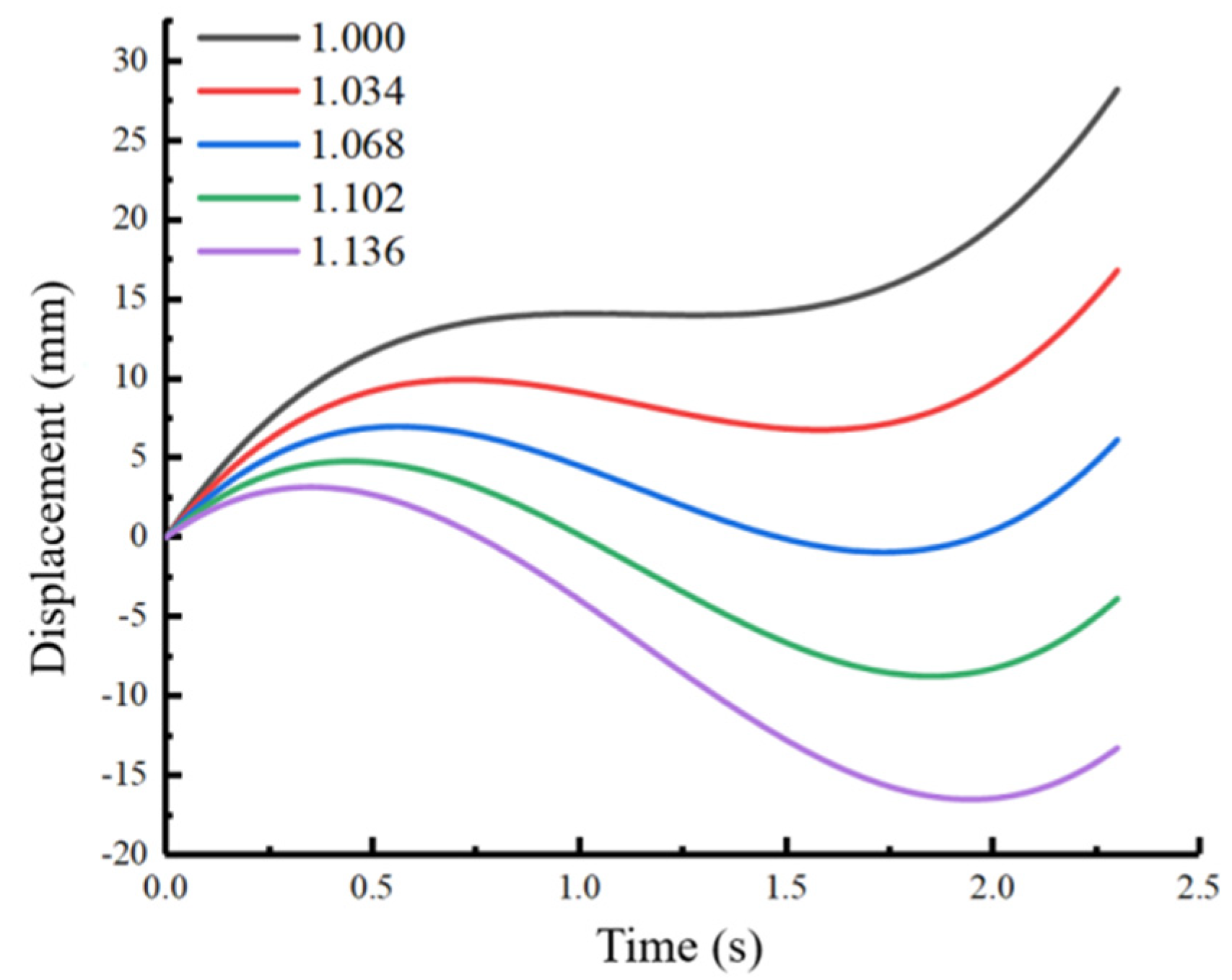
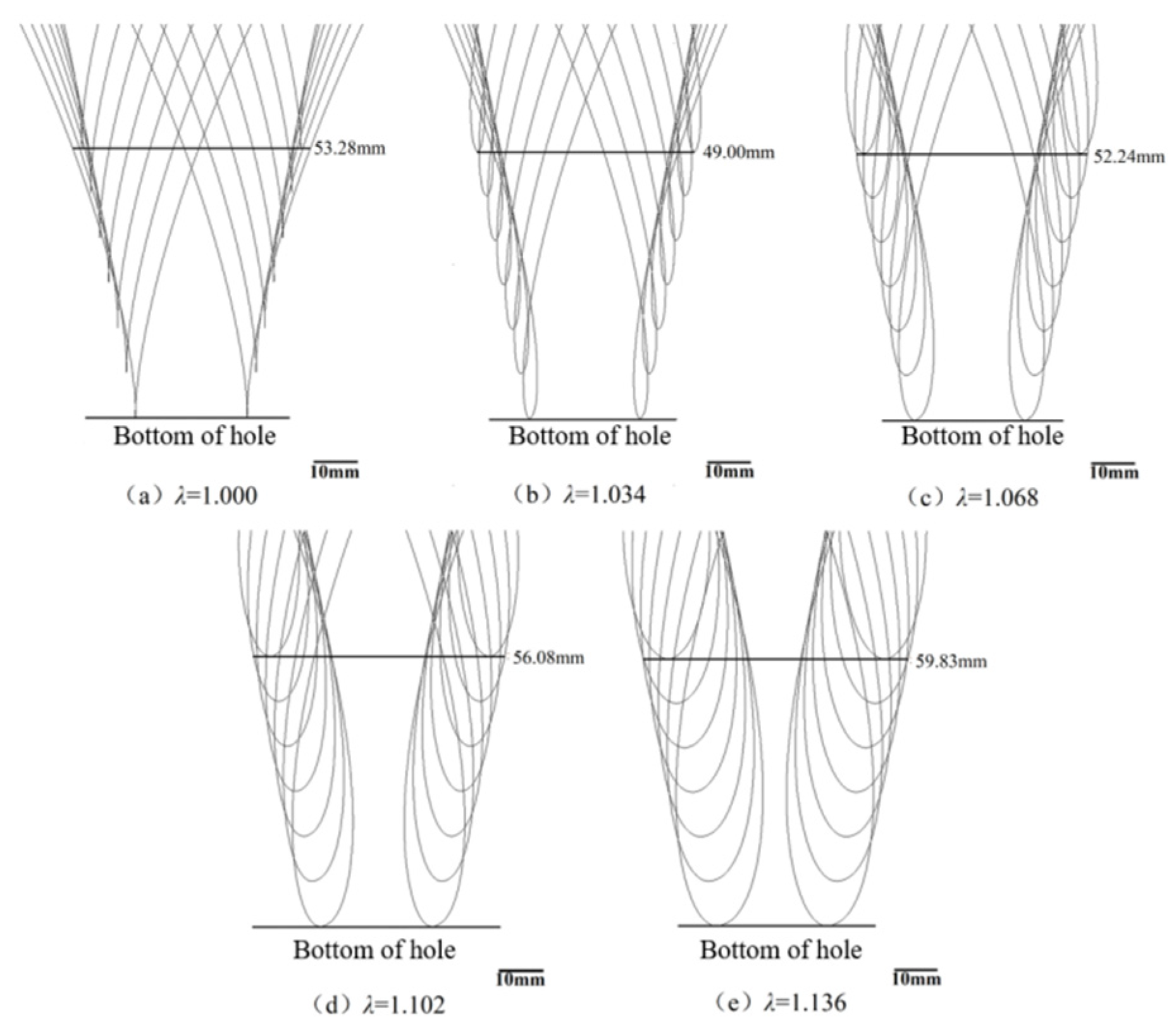
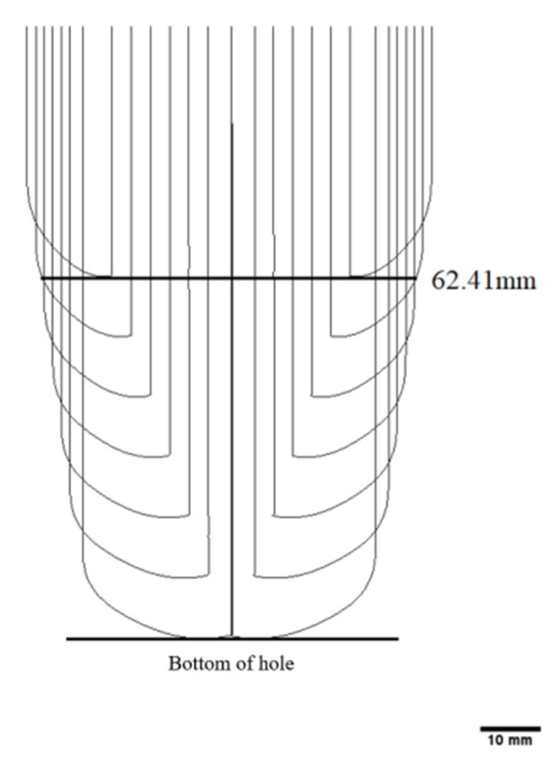
The Effect of the Transplanting Characteristic Coefficient on the Longitudinal Dimension of the Hole Opening

The transplanting angle was 90°, the transplanting frequency was 36 plants·min−1, and the transplanting characteristic coefficient was set to 1.000, 1.034, 1.068, 1.102, and 1.136. The envelope hole openings formed under different transplanting characteristic coefficients λ are shown in Figure 8. The bottom end of the envelope line was set as the hole-opening bottom, and the dimension of the lateral direction of the envelope line at 60 mm from the hole-opening bottom was used to simulate the hole-opening dimension, which is the theoretical hole-opening dimension of the transplanting unit. As the transplanting characteristic coefficients λ increases, the ring buckle of the kinematic envelope line increases, and the dimension of the envelope line first decreases and then increases. When λ = 1.034, the envelope hole opening formed by the kinematic track of the transplanting unit is the smallest, and the hole-opening dimension is 49.00 mm. When λ = 1.068, the displacement under the mulching film at the lower end-point of the transplanting unit is the smallest, and the time for the upper end to enter the soil is short because the transplanting unit is wedge-shaped with a wide top and a narrow bottom. The smaller the trochoid loop of the track of the transplanting unit, the smaller the displacement under the mulching film at the upper end, so the dimension of the trochoid loop of the track also affects the dimension of the envelope hole opening.

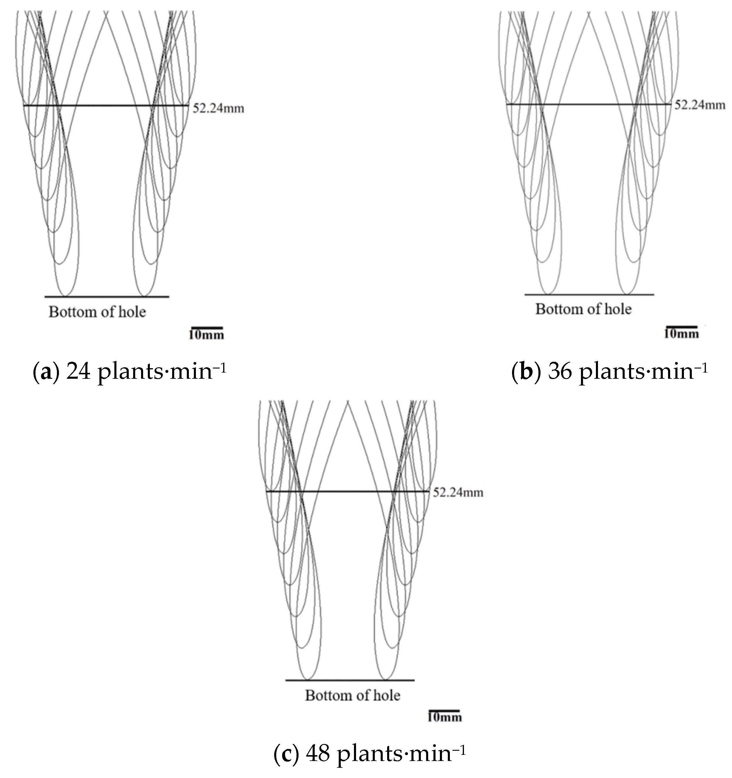
The Effect of the Transplanting Frequency on the Longitudinal Dimension of the Hole Opening

The transplanting angle was 90°, and the transplanting characteristic coefficient λ was 1.068. Three transplanting frequencies of 24, 36, and 48 plants·min−1 were selected for the simulation experiments. With the increase in the transplanting frequency, the speed of hole-opening formation is also accelerated, the dimensions of the envelope do not change, and the dimensions of the envelope trochoid are the same, as shown in Figure 9. When the transplanting angle and the transplanting characteristic coefficient λ remain unchanged, the longitudinal hole-opening dimension of the envelope formed by the transplanting unit is independent of the transplanting frequency. So, in the simulation experiment, the transplanting characteristic coefficient λ was 1.068, and the transplanting frequency was 36 plants·min−1. In addition, the transplanting unit is obliquely inserted into the soil at the maximum transplanting angle but does not make an inclined hole opening; it is advisable to take the adjustable maximum limit of the transplanting angle of the transplanting unit as the experimental maximum (95°), also consider the value of the transplanting angle follows the principle of symmetry.

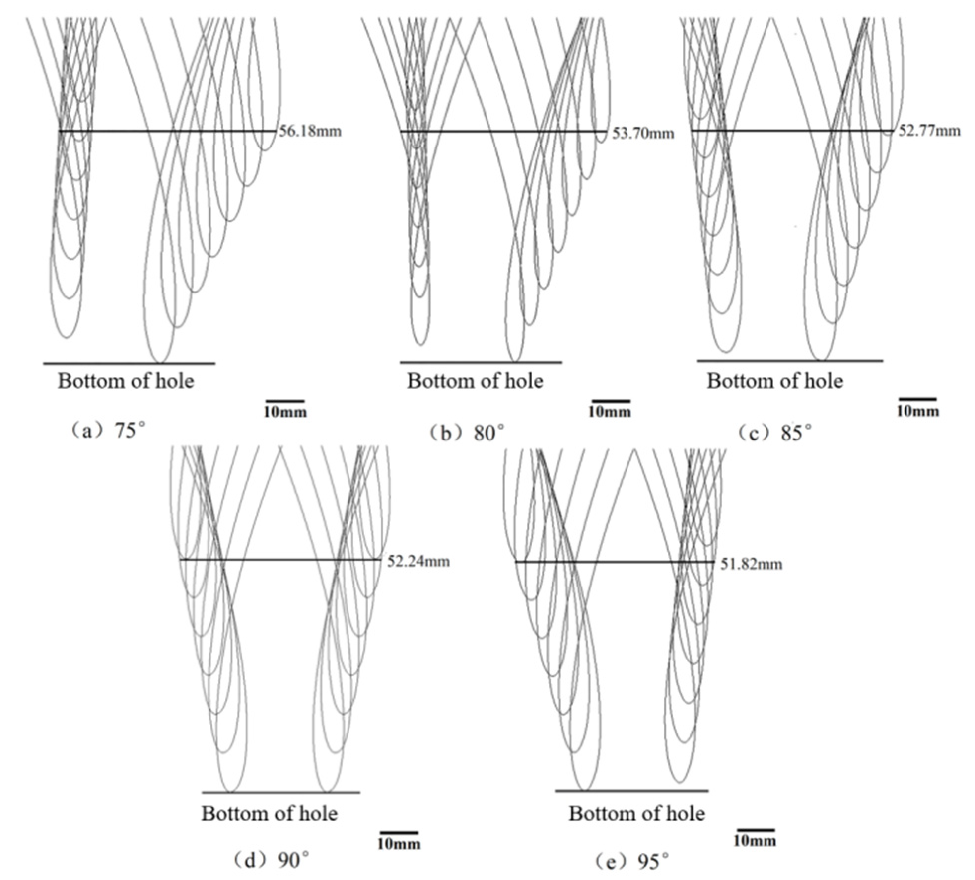
The Effect of the Transplanting Angle on the Longitudinal Dimension of the Hole Opening

According to the above, in the simulation experiment, the transplanting characteristic coefficient λ was 1.068, and the transplanting frequency was 36 plants·min−1. We selected five transplanting angles, 75°, 80°, 85°, 90°, and 95°, to perform the simulation experiment, as shown in Figure 10. As the transplanting angle increases, the horizontal span of the envelope formed on the left side of the duckbill gradually increases, and the envelope becomes more and more scattered. However, the span of the envelope formed on the right side of the duckbill gradually shrinks, and the envelope becomes more and more compact. Thus, with the increase in the transplanting angle, the displacement on the left side of the duckbill of the transplanting unit increases, the displacement on the right side of the duckbill decreases, and the envelope hole opening decreases. When the transplanting angle is 95°, the envelope hole opening is the smallest, and the longitudinal dimension of the hole opening is 51.82 mm. In the actual transplanting operation, the transplanting angle should be adjusted accordingly to achieve the purpose of reducing the hole opening.

The Lateral Dimension of the Hole Opening

The kinematic envelope formed by the transplanting unit in the lateral direction during the transplanting process is shown in Figure 11. Since the lateral kinematic only is the duckbill opening and closing movement, the formation of the lateral hole opening is only related to the dimension the cam that controls the duckbill opening and closing and is independent of other kinematic parameters. Therefore, the theoretical dimension of the lateral hole opening formed by the transplanting unit during the transplanting process is 62.41 mm.

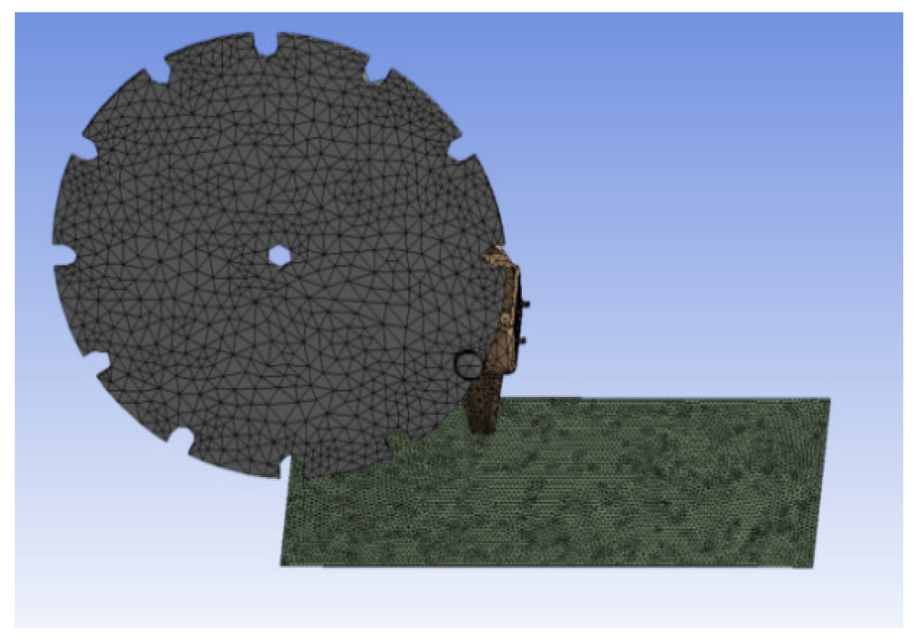
2.4. Dynamic Simulation Analysis Based on ANSYS WORKBENCH

Since the envelope hole opening based on ADAMS is formed by the kinematic track of the transplanting unit, the dimension of the envelope hole opening is the theoretical value of the hole opening. During the transplanting operation process, the plastic mulching film is tough, so the shear stress of the mulching film is also different for different transplanting parameters. In order to obtain the influence of different experimental factors on the maximum shear stress in the process of hole-opening formation, a dynamic simulation of the process of the transplanting unit damaging the mulching film was carried out based on the LS−DYNA module of ANSYS WORKBENCH. In the simulation, only the structural model involved in the film-breaking process was retained, and the model was simplified. The simulation model is shown in Figure 12.
The transplanting unit and the transplanting disc are made of structural steel and were set as rigid bodies. The thickness of the mulching film was set to 1 mm, and it was set as a flexible body. The main material properties of the mulching film are shown in Table 2.
A tetrahedral mesh shape was selected to mesh the simulation model, as shown in Figure 13. The grid dimensions of the transplanting disc and the transplanting unit were set to 5 mm, and the grid dimension of the mulching film was set to 2 mm. After meshing, a driver was added to the simulation model, a fixed constraint was added to the mulching film, and the simulation time was set to 3 s.

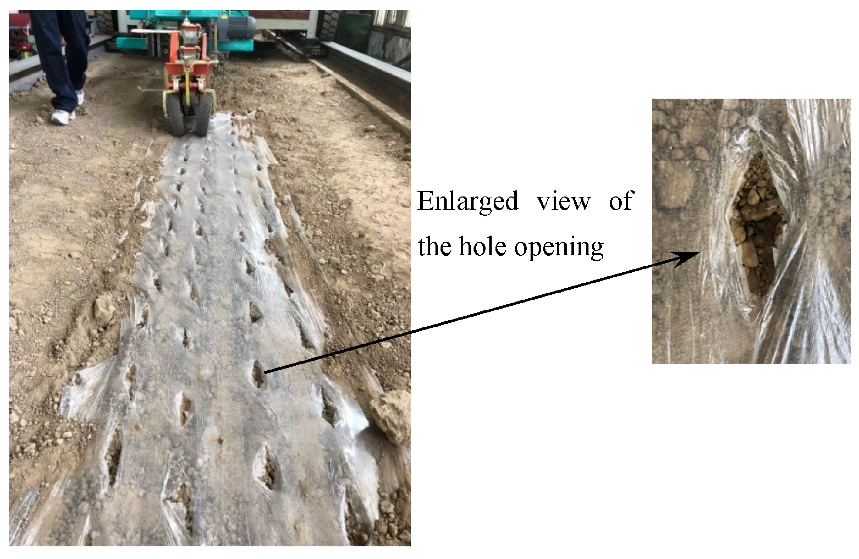
2.5. The Film-Breaking Experiment on the Soil−Tank Test Bench

The film-breaking experiment was carried out on a soil-tank test bench, as shown in Figure 14. The soil-tank test bench is the TCC−II electric four-wheel-drive soil-tank test bench produced by Harbin Bona Technology Co., Ltd., Harbin, Heilongjiang Province, China. Other experimental equipment and tools included a transplanting device, a mulching film (80 cm width), a three-phase asynchronous gear reduction motor, and a steel ruler.
The mulching film was first laid in the soil tank, and the laying distance was not less than 5 m. The dibble-type transplanting device moved forward with the soil-tank experiment vehicle, and the transplanting units were driven by the three-phase asynchronous gear reduction motor. Taking the transplanting characteristic coefficient, the transplanting frequency, and the transplanting angle as the experimental factors, 3 rows were used for experiments run under each experimental factor, and the number of hole openings in each row was not less than 20. A straight steel ruler was used to measure the size of every hole opening in the mulching film. The dimensions of the largest hole opening formed in the longitudinal and lateral directions of the mulching film were measured. The experiment was repeated three times, and then the average of the measurements was obtained.

3. Results and Discussion

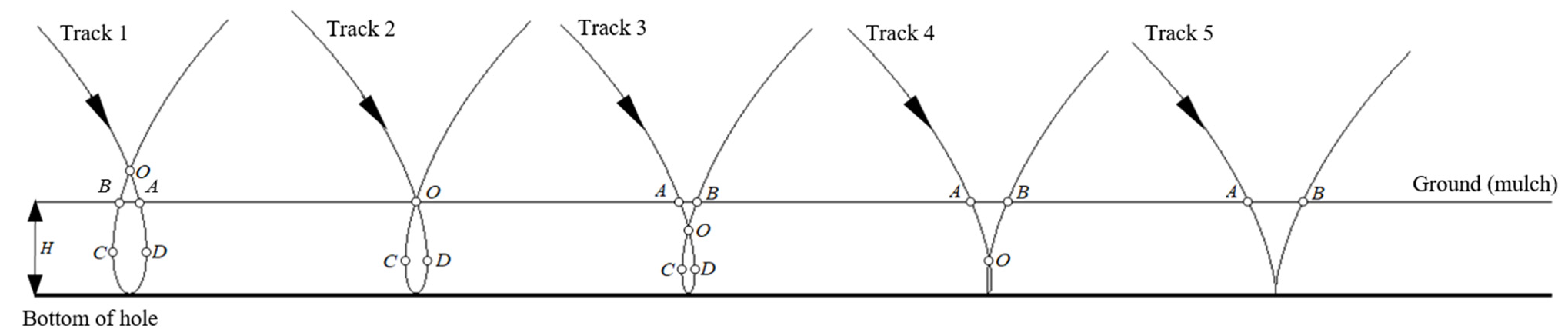
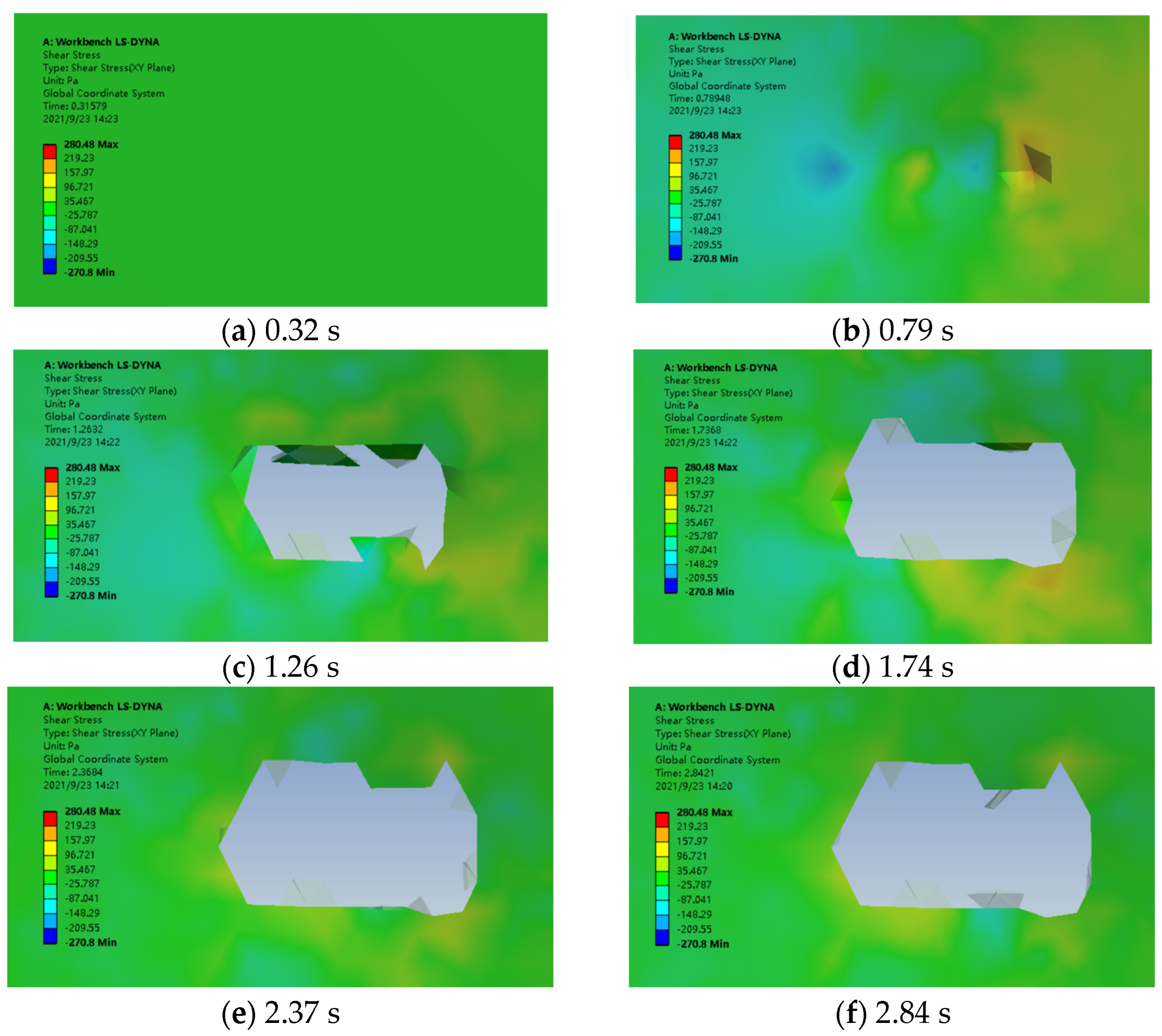
3.1. The Process of Hole-Opening Formation in Mulching Film

The simulation time for the process of hole-opening formation in a mulching film was 3 s. The pressure nephograms of the process of hole-opening formation in a mulching film at different times are shown in Figure 15.
The pressure nephogram of the mulching film at 0.32 s shows that the transplanting unit has not yet contacted the mulching film (Figure 15a). When the simulation time is 0.79 s, the transplanting unit begins to insert the mulching film (Figure 15b). At this time, the mulching film has not been broken, but it is subjected to the greatest stress in the forward direction of the transplanter. Figure 15c,d show the hole-opening formation stage of the mulching film, and the stress on the mulching film is less than the stress before 0.79 s. Figure 15e,f are the pressure nephograms after the hole opening in the mulching film has formed.
From the pressure nephograms of the mulching film at different times, it can be seen that the stress change on both sides of the longitudinal hole of the mulching film is more obvious, and the shear stress of the mulching film on both sides of the lateral hole is relatively uniform. The stress of the mulching film in the longitudinal direction is greater than that in the lateral direction, and the size of the hole formed in the longitudinal direction is larger than that in the lateral direction.

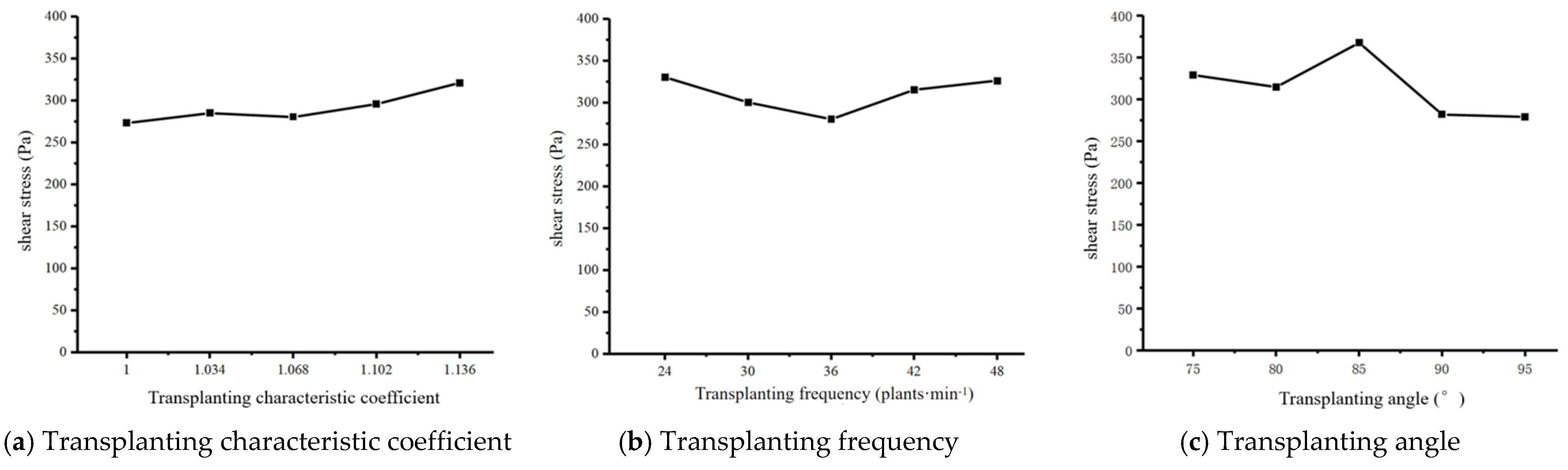
3.2. The Effect of the Maximum Shear Stress on the Mulching Film under Different Experimental Factors

The statistical curves of the maximum shear stress of the mulching film under different experimental factors are shown in Figure 16. With the increase in the transplanting characteristic coefficient λ , the maximum shear stress shows an increasing trend. When the transplanting characteristic coefficient λ = 1.000, the maximum shear stress is the smallest. With the increase in the transplanting frequency, the maximum shear stress first decreases and then increases. When the transplanting frequency is 36 plants·min−1, the maximum shear stress is the smallest. With the increase in the transplanting angle, the maximum shear stress first increases and then decreases. When the transplanting angle is 85°, the maximum shear stress is the largest. When the transplanting angle is 95°, the maximum shear stress is the smallest. The smaller the shear stress of the mulching film during the formation of the hole opening, the smaller the damage caused by the transplanting unit to the mulching film, and the smaller the size of the hole opening. Therefore, the transplanting operation should be carried out under operating parameters that subject the mulching film to less shear stress.

3.3. The Effect of Different Experimental Factors of the Mulching Film on the Size of the Hole Opening

The effects of different operating parameters on the dimensions of the hole opening of a mulching film are shown in Figure 17.
With the increase in the transplanting characteristic coefficient λ , the longitudinal and lateral dimensions of the hole opening first decrease and then increase. The longitudinal dimension of the hole opening ranges from 99.20 to 120.40 mm, and the lateral dimension ranges from 31.67 to 36.53 mm. When the transplanting characteristic coefficient λ = 1.034, the dimension of the hole opening is the smallest. When the characteristic coefficient λ = 1.136, the dimension of the hole opening is the largest. At different transplanting frequencies, the longitudinal dimension of the hole opening ranges from 102.53 to 107.73 mm, and the lateral dimension ranges from 31.67 to 33.87 mm. When the transplanting frequency is 36 plants·min−1, the hole-opening dimension is the smallest. When the transplanting frequency is 48 plants·min−1, the hole-opening dimension is the largest. With different transplanting angles, the longitudinal dimension of the hole opening ranges from 100.47 to 116.33 mm, and the lateral dimension ranges from 31.67 to 37.07 mm. The longitudinal dimension of the hole opening decreases with the increase in the transplanting angle. When the transplanting angle is 95°, the longitudinal dimension is the smallest, while the lateral dimension is the smallest when the transplanting angle is 90°.
From the above-mentioned analysis, it can be seen that the influence of the transplanting characteristic coefficient and the transplanting angle on the longitudinal size of the hole opening is the same as that shown by the kinematic simulation results (Figure 8 and Figure 10). The influence of the transplanting frequency on the longitudinal dimension of the hole opening is related to the shear stress of the mulching film in the dynamic simulation (Figure 15 and Figure 16). The longitudinal dimension of the hole opening is larger than the theoretical dimension, while the lateral dimension of the hole opening is smaller than the theoretical dimension. From the results in Figure 17, we can see that the movement of the transplanting unit in the direction of the forward velocity causes great damage to the mulching film, causing the mulching film to tear in the longitudinal direction and making the actual dimension of the hole opening larger than the theoretical dimension of the hole opening.

4. Conclusions

(1)
The kinematic track of the lower end-point of the transplanting unit was analyzed, and the kinematic track equation was established. According to the results calculated by the kinematic track Equation (11), the actual transplanting depth of the vegetable seedling is 60 mm, the transplanting characteristic coefficient λ of the minimum displacement of the lower end of the transplanting unit under the mulching film is 1.068, and the horizontal displacement of the transplanting unit under the mulching film is minimal.
(2)
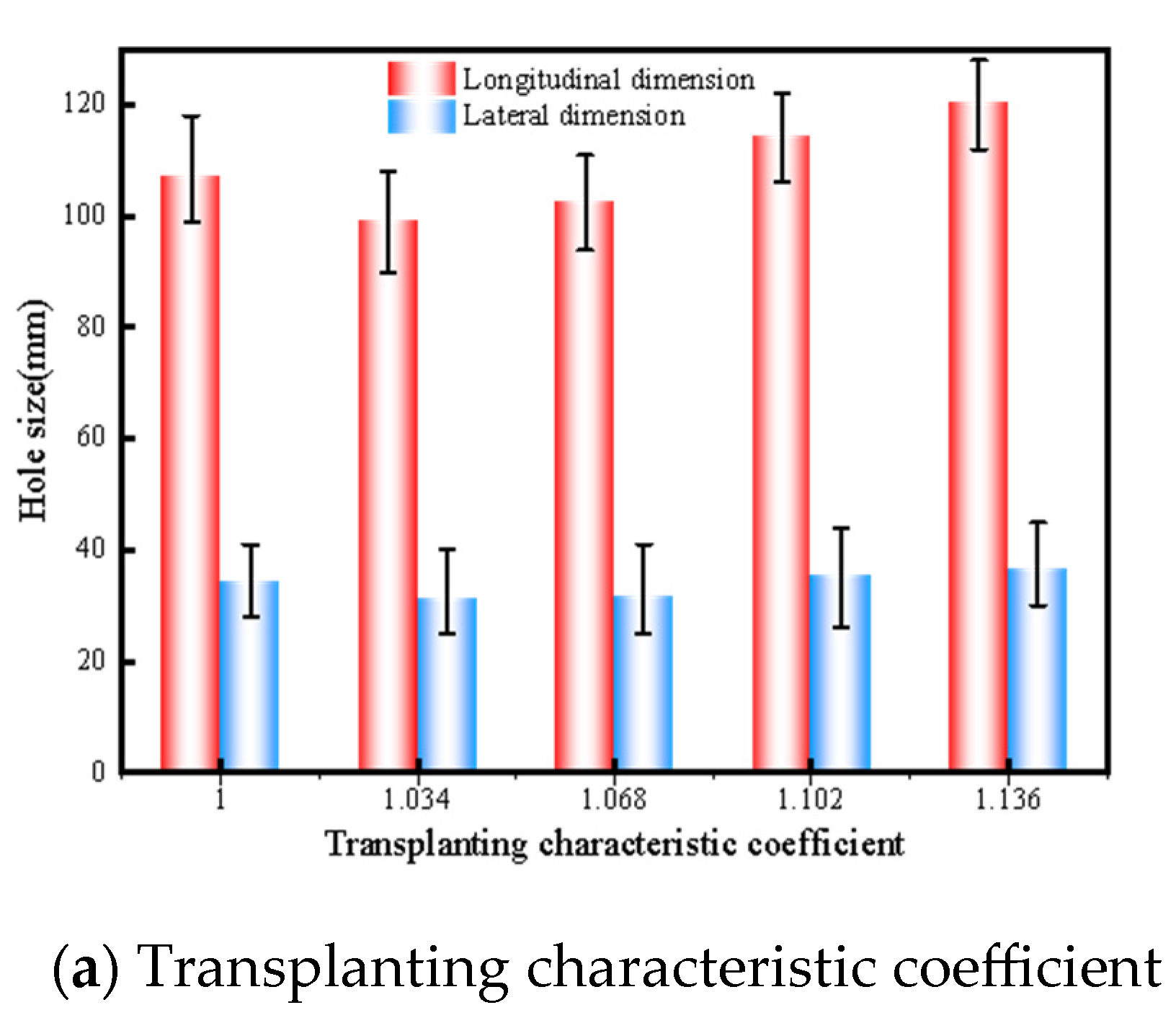
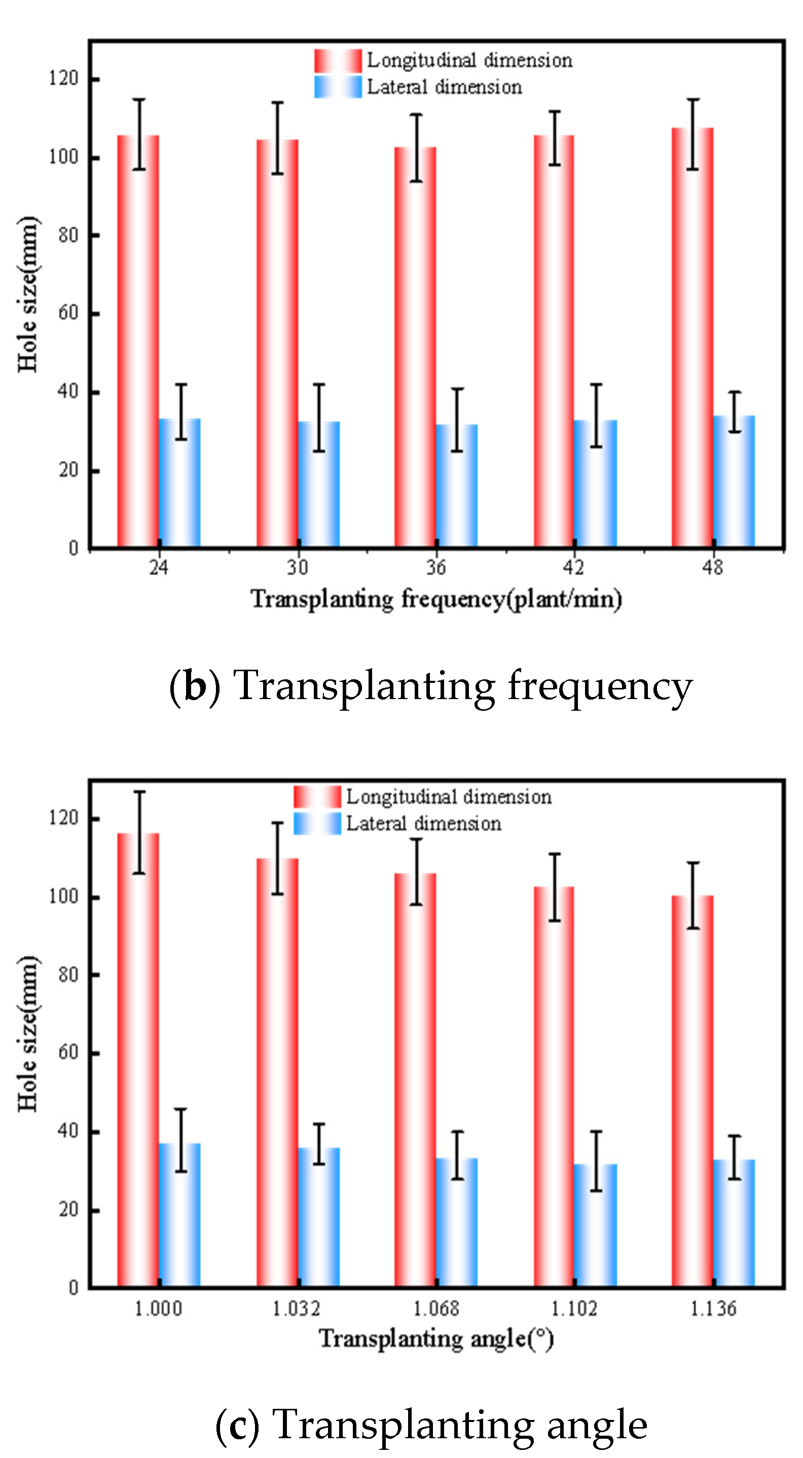
The results of the ADAMS simulation show that the transplanting characteristic coefficient, the transplanting frequency, and the transplanting angle have no effect on the lateral hole-opening dimension of the envelope, and the transplanting frequency has no effect on the longitudinal dimension of the hole opening. But when the longitudinal dimension of the hole opening of the envelope is the smallest, the transplanting characteristic coefficient is 1.034, and the transplanting angle is 95°. Therefore, in the actual transplanting operation, in order to reduce the size of the hole opening in the mulching film, the transplanting characteristic coefficient and the transplanting angle should be reasonably controlled.
(3)
The pressure nephogram from the ANSYS WORKBENCH finite element analysis shows that the maximum shear stress of the mulching film in the longitudinal direction is greater than that in the lateral direction. When the transplanting characteristic coefficient, the transplanting frequency, and the transplanting angle are 1.000, 36 plants·min−1, and 95°, respectively, the maximum shear stress of the mulching film in the process of hole-opening formation is the smallest. So, in the process of transplanting, the operating parameters with less shear stress on the mulching film should be selected as much as possible to reduce the occurrence of mulching-film damage and tearing.
(4)
The optimal parameters were verified through a film-breaking experiment on a soil-tank test bench. Under the conditions of different transplanting characteristic coefficients, transplanting frequencies, and transplanting angles, the differences between the maximum and minimum sizes of the longitudinal dimension of the hole opening in the mulching film are 21.20 mm, 5.20 mm, and 15.86 mm, respectively, and the differences between the maximum and minimum sizes of the lateral dimension of the hole opening in the mulching film are 4.86 mm, 2.20 mm, and 5.40 mm, respectively. The larger the difference between the maximum size and the minimum size of the hole opening in the mulching film, the more significant the influence of the experimental factors on the hole-opening dimensions. The transplanting characteristic coefficient has the most significant effect on the longitudinal dimension of the hole opening, the transplanting angle has the most significant effect on the lateral dimension of the hole opening, and the transplanting frequency has no significant effect on the dimensions of the hole opening. The test results show that the influence of each test factor on hole-opening formation in the mulching film is the same as shown by the simulation analysis results, and the simulation test results have important reference and guiding significance for the size of the actual hole opening.

Author Contributions

Conceptualization, X.Z., J.H. and J.Z.; methodology, X.Z. and Z.H.; software, Z.H. and H.Y.; validation, J.Z., X.Z. and J.H.; formal analysis, J.Z.; investigation, X.Z.; resources, J.H.; data curation, H.Y.; writing—original draft preparation, Z.H. and X.Z.; writing—review and editing, X.Z.; visualization, X.Z.; supervision, J.H.; project administration, Y.L.; funding acquisition, J.Z. All authors have read and agreed to the published version of the manuscript.

Funding

This research was funded by the National Key R&D Program (2021YFD1901104−5), Key R&D Program of Hebei (21327005D), State Key Laboratory of North China Crop Improvement and Regulation (NCCIR2024ZZ−12), and S&T Program of Hebei (23567601H). The central government guides local funds for scientific and technological development (Grant No. 236Z7202G), and the APC was funded by [2021YFD1901104−5].

Institutional Review Board Statement

Not applicable.

Data Availability Statement

The datasets used and/or analyzed during the current study are available from the corresponding author on reasonable request.

Conflicts of Interest

The authors declare no conflicts of interest.

References

  1. Li, L.; Wu, W.L.; Giller, P.; O’Halloran, J.; Liang, L.; Peng, P.; Zhao, G. Life cycle assessment of a highly diverse vegetable multi-cropping system in Fengqiu County, China. Sustainability 2018, 10, 983. [Google Scholar] [CrossRef]
  2. Yin, D.Q.; Wang, J.Z.; Zhang, S.; Zhang, N.Y.; Zhou, M.L. Optimized design and experiments of a rotary-extensive-type flowerpot seedling transplanting mechanism. Int. J. Agric. Biol. Eng. 2019, 12, 45–50. [Google Scholar] [CrossRef]
  3. Ji, J.T.; Cheng, Q.; Jin, X.; Zhang, Z.H.; Xie, X.L.; Li, M.Y. Design and test of 2ZLX-2 transplanting machine for oil peony. Int. J. Agric. Biol. Eng. 2020, 13, 61–69. [Google Scholar] [CrossRef]
  4. Wen, Y.S.; Zhang, J.X.; Tian, J.Y.; Duan, D.S.; Zhang, Y.; Tan, Y.Z.; Yuan, T.; Li, X. Design of a traction double-row fully automatic transplanter for vegetable plug seedlings. Comput. Electron. Agric. 2021, 182, 106017. [Google Scholar] [CrossRef]
  5. Jin, X.; Li, D.Y.; Ma, H.; Ji, J.T.; Zhao, K.X.; Pang, J. Development of single row automatic transplanting device for potted vegetable seedlings. Int. J. Agric. Biol. Eng. 2018, 11, 67–75. [Google Scholar] [CrossRef]
  6. Uchiyama, H.; Wada, Y.; Hatanaka, Y.; Hirata, Y.; Taniguchi, M.; Kadota, K.; Tozuka, Y. Solubility and permeability improvement of quercetin by an interaction between α-glucosyl stevia nano-aggregates and hydrophilic polymer. J. Pharm. Sci. 2019, 108, 2033–2040. [Google Scholar] [CrossRef] [PubMed]
  7. Kumar, N.; Upadhyay, G.; Choudhary, S.; Patel, B.; Naresh Chhokar, R.S.; Gill, S.C. Resource conserving mechanization technologies for dryland agriculture. In Enhancing Resilience of Dryland Agriculture under Changing Climate: Interdisciplinary and Convergence Approaches; Springer Nature: Singapore, 2023; pp. 657–688. [Google Scholar]
  8. Hu, S.; Hu, M.; Yan, W.; Zhang, W. Design and Experiment of an Integrated Automatic Transplanting Mechanism for Picking and Planting Pepper Hole Tray Seedlings. Agriculture 2022, 12, 557. [Google Scholar] [CrossRef]
  9. Quan, W.; Wu, M.; Dai, Z.; Luo, H.; Shi, F. Design and Testing of Reverse-Rotating Soil-Taking-Type Hole-Forming Device of Pot Seedling Transplanting Machine for Rapeseed. Agriculture 2022, 12, 319. [Google Scholar] [CrossRef]
  10. Vlahidis, V.; Rosca, R.; Cârlescu, P.-M. Evaluation of the Functional Parameters for a Single-Row Seedling Transplanter Prototype. Agriculture 2024, 14, 388. [Google Scholar] [CrossRef]
  11. Fu, J.; Cui, Z.; Chen, Y.; Guan, C.; Chen, M.; Ma, B. Simulation and Experiment of Compression Molding Behavior of Substrate Block Suitable for Mechanical Transplanting Based on Discrete Element Method (DEM). Agriculture 2023, 13, 883. [Google Scholar] [CrossRef]
  12. Du, S.; Wang, W.B.; Wang, J.K. Parameters research of dibble-type transplanter for the smallest mulch-film damage. J. Chin. Agric. Mech. 2016, 37, 5–8+17. (In Chinese) [Google Scholar]
  13. Feng, J.; Qin, G.; Song, W.T.; Liu, Y.J. The Kinematic analysis and design criteria of the dibble-type planting devices. Trans. CSAM 2002, 33, 48–50. (In Chinese) [Google Scholar]
  14. Cui, W.; Zhao, L.; Song, J.N.; Lin, J.T. Kinematic analysis and experiment of dibble-type planting device. Trans. CSAM 2012, 43 (Suppl. S1), 35–38+34. (In Chinese) [Google Scholar]
  15. Li, X.Y.; Wang, Y.W.; Lu, G.C.; Zhang, B.; Zhang, H.J. Optimization design and experiment of dibble-type transplanting device. Trans. CSAE 2015, 31, 58–64. (In Chinese) [Google Scholar]
  16. Liu, Y.; Mao, H.P.; Wang, T.; Li, B.; Li, Y.X. Collision optimization and experiment of tomato plug seedling in basket-type transplanter. Trans. CSAM 2018, 49, 143–151. (In Chinese) [Google Scholar]
  17. Tian, Y.; Li, X.Y.; Zhang, H.J.; Chi, M.L.; Zhang, X.J. Design and the motion simulation for spatial cam of dibble-type planting device. J. Agric. Mech. Res. 2014, 36, 62–65+69. (In Chinese) [Google Scholar]
  18. Zhang, X.Z.; Li, X.Y.; Tian, Y.; Chi, M.L. Three-dimensional modeling and motion simulation analysis of dibble-type planting device based on Pro/E. J. Agric. Mech. Res. 2014, 36, 87–90. (In Chinese) [Google Scholar]
  19. Jin, X.; Li, S.J.; Yang, X.J.; Yan, H.; Wu, J.M.; Mao, Z.H. Motion analysis and parameter optimization for pot seedling planting mechanism based on up-film transplanting. Trans. CSAM 2012, 43 (Suppl. S1), 29–34. (In Chinese) [Google Scholar]
  20. Xue, X.L.; Li, L.H.; Xu, C.L.; Li, E.Q.; Wang, Y.J. Optimized design and experiment of a fully automated potted cotton seedling transplanting mechanism. Int. J. Agric. Biol. Eng. 2020, 13, 111–117. [Google Scholar] [CrossRef]
  21. Li, H.; Cao, W.B.; Li, S.F.; Fu, W.; Liu, K.Q. Kinematic analysis and test on automatic pick-up mechanism for chili plug seedling. Trans. CSAE 2015, 31, 20–27. (In Chinese) [Google Scholar]
  22. Zhou, M.F.; Huang, Z.J.; Shi, L.D.; Yu, G.H.; Zhao, X.; Liu, P.F. Improvement design and experimental analysis of automatic transplanting of flower plug seedlings. J. Chin. Agric. Mech. 2019, 40, 10–16. (In Chinese) [Google Scholar]
  23. Zhou, M.F.; Xu, J.J.; Tong, J.H.; Yu, G.H.; Zhao Xiong Xie, J. Design and experiment of integrated automatic transplanting mechanism for taking and planting of flower plug seedling. Trans. CSAE 2018, 34, 44–51. (In Chinese) [Google Scholar]
Figure 1. The whole structure of the transplanting device. (a) A sectional view of the transplanting device. 1. Shell; 2. dibble-type transplanting unit; 3. transplanting disc; 4. sprocket; 5. spindle; 6. dibble axis. (b) An axonometric view of the transplanting device without the shell. 7. Eccentric disc; 8. eccentric axis; 9. eccentric connection.
Agriculture 14 00494 g001
Figure 2. A schematic diagram of the working principle of the dibble-type transplanting device. 1. Dibble-type transplanting unit; 2. eccentric disc; 3. transplanting disc.
Agriculture 14 00494 g002
Figure 3. A schematic diagram of the track of the dibble-type transplanting device.
Agriculture 14 00494 g003
Figure 4. The hole-forming kinematic track of the transplanting unit with different transplanting characteristic coefficients λ .
Agriculture 14 00494 g004
Figure 5. Vertical displacement curve of the bottom end-point of the transplanting unit.
Agriculture 14 00494 g005
Figure 6. Horizontal displacement curve under the mulching film of the lower end-point of the transplanting unit.
Agriculture 14 00494 g006
Figure 7. A schematic diagram of the simulated picking point position of the transplanting unit.
Agriculture 14 00494 g007
Figure 8. Diagrams of envelope hole openings with different transplanting characteristic coefficients. (a) The envelope hole opening at λ = 1.000. (b) The envelope hole opening at λ = 1.034. (c) The envelope hole opening at λ = 1.068. (d) The envelope hole opening at λ = 1.102. (e) The envelope hole opening at λ = 1.136.
Agriculture 14 00494 g008
Figure 9. Diagrams of envelope hole openings with different transplanting frequencies. (a) The envelope hole opening when the transplanting frequency is 24 plants·min−1. (b) The envelope hole opening when the transplanting frequency is 36 plants·min−1. (c) The envelope hole opening when the transplanting frequency is 48 plants·min−1.
Agriculture 14 00494 g009
Figure 10. Diagrams of envelope hole openings with different transplanting angles. (a) The envelope hole opening when the transplanting angle is 75°. (b) The envelope hole opening when the transplanting angle is 80°. (c) The envelope hole opening when the transplanting angle is 85°. (d) The envelope hole opening when the transplanting angle is 90°. (e) The envelope hole opening when the transplanting angle is 95°.
Agriculture 14 00494 g010
Figure 11. Envelope diagram of the transplanting unit in the lateral direction.
Agriculture 14 00494 g011
Figure 12. Dynamic simulation model of film-breaking experiment of the transplanting unit. 1. Transplanting disc; 2. transplanting unit; 3. mulching film.
Agriculture 14 00494 g012
Figure 13. Meshing for the simulation model.
Agriculture 14 00494 g013
Figure 14. Film-breaking experiment on soil-tank test bench.
Agriculture 14 00494 g014
Figure 15. Pressure nephograms of the mulching film during the hole opening forming process.
Agriculture 14 00494 g015
Figure 16. The effect of the maximum shear stress on the mulching film under different experimental factors.
Agriculture 14 00494 g016
Figure 17. The effects of different experimental factors on the dimensions of the hole opening of a mulching film.
Agriculture 14 00494 g017aAgriculture 14 00494 g017b
Table 1. The maximum displacement of the lower end-point under the mulching film with different transplanting characteristic coefficients.
λ Maximum Displacement/(mm)
1.00028.22
1.03416.81
1.0687.91
1.10213.53
1.13619.68
Table 2. Table of mulching-film material properties.
Material
Properties
Density (kg·m−3)Young’s Modulus (MPa)Poisson’s
Ratio
Yield Stress (MPa)
Value9400.10.452 × 10−4
Disclaimer/Publisher’s Note: The statements, opinions and data contained in all publications are solely those of the individual author(s) and contributor(s) and not of MDPI and/or the editor(s). MDPI and/or the editor(s) disclaim responsibility for any injury to people or property resulting from any ideas, methods, instructions or products referred to in the content.

