Article

Evaluation of the Functional Parameters for a Single-Row Seedling Transplanter Prototype

by
Virgil Vlahidis
1,*,
Radu Roșca
1 and
Petru-Marian Cârlescu
2
1
Department of Pedotechnics, Faculty of Agriculture, “Ion Ionescu de la Brad” Iasi University of Life Sciences, 700490 Iași, Romania
2
Department of Food Technologies, Faculty of Agriculture, “Ion Ionescu de la Brad” Iasi University of Life Sciences, 700490 Iași, Romania
*
Author to whom correspondence should be addressed.
Agriculture 2024, 14(3), 388; https://doi.org/10.3390/agriculture14030388
Submission received: 15 December 2023 / Revised: 21 February 2024 / Accepted: 24 February 2024 / Published: 28 February 2024
(This article belongs to the Special Issue Design, Optimization and Analysis of Agricultural Machinery)

Abstract

:
The development of an automatic seedling planting system for micro-farms requires testing under laboratory conditions to verify the theoretical relationships between essential functional parameters, working speed and planting time. The constructive dimensional values of the prototype, the results measured in stationary mode directly on the transplanter and the auxiliary equipment and the direct determinations of the working parameters on the soil bin are used. Depending on the characteristics of the soil bin trolley, a range of speeds is chosen at which the machine is tested. The data obtained validate the correct operation of the prototype at speeds close to those determined theoretically for the following indicators: distance between plants per row, planter wheel slippage, misplanted seedlings rate and seedling frequency, with results comparable to existing agronomic standards. Once the appropriate operating speeds of the machine have been obtained, between 0.304 and 0.412 m/s, with planting frequencies between 0.899 and 1.157 s−1 (respectively, 53.94 and 69.42 seedlings per minute), optimizations and adjustments of some machine components can be made, for subsequent testing in real field conditions.

1. Introduction

All over the world, the automation of seedling planting aims to reduce the shortage of skilled labor, to fit the planting operation into the optimal period and to obtain higher quality indicators than manual planting.
The trend is underlined by intensive research and planting machines introduced on horticultural farms in the last 20 years.
There are currently several directions for automated seedling planting. The first is the development of complex, high-productivity, towed or self-propelled automatic machines by companies from Australia, the US, Great Britain, Italy and Sweden. Characteristic of these machines is their low service staff, high travel speed, long autonomy between feedings and adaptability to different planting schemes; purchase and operating prices are high.
The underlying principles of these machines are air-pruning technology for growing seedlings [1,2] and extraction based either on vacuum from the growth cells of the trays [3] or by finger, needle, or combination systems [4,5].
Another direction of research was initiated in Japan by the agricultural divisions of Yanmar Noki, Co., (Osaka, Japan) Kubota Co., Ltd. (Osaka, Japan) and Iseki Noki Co., Ltd. (Matsuyama-shi, Japan), which developed self-propelled automatic seedling planters derived from rice planters for small and medium-sized Japanese farms. They were designed to be serviced by the machine’s sole operator, have a stock of pulp mold cell seedlings trays, use a holding claw seedling extractor and perform a reduced range of planting schemes [6].
The latest approach to plantation automation can be found in research from China and India. Basically, the aim is to use robotic technology to perform the various operations required for planting: seedling extraction from the growing cell [7], seedling distribution [8], selection before planting [9] and guidance of planting machines in greenhouses [10]. Characteristically, in parallel with equipping these planting machines with high-tech components that can be integrated into precision farming, the primary goal remains the trend to develop small-farm-oriented planting systems to achieve better quality and productivity indicators, as illustrated in the mentioned research in India [8] and China [10].
Meanwhile, vegetable farms in Romania are characterized by a preponderance of subsistence micro-farms, of which more than 70% have areas of less than 5 ha; they face a decline in specialized labor and insufficient financial resources for investments on the scale of automatic planting machines and the related standardized seedling production system.
These considerations argue for the need to obtain a seedling technology accessible to small farmers in terms of price and complexity of use, with low and unskilled labor, comprising a simple construction transplanting machine with gravitational extraction, transport and distribution of seedlings with prefabricated Jiffy-type substrate, grown in rigid original plastic trays, in protected shelters. The planting machine is set up as a mono-section, fed with trays of seedlings by an operator, who also drives the aggregate formed by the machine with a walking-behind tractor.
Although it is still aimed at small farms, in comparison with the other approaches presented above, the main feature of the prototype, constructive and functional simplicity, is characterized by certain particularities in all the segments that define the interdependent system of an automatic planting technology: seedling with nutrient substrate, growing medium and automatic planting machine.
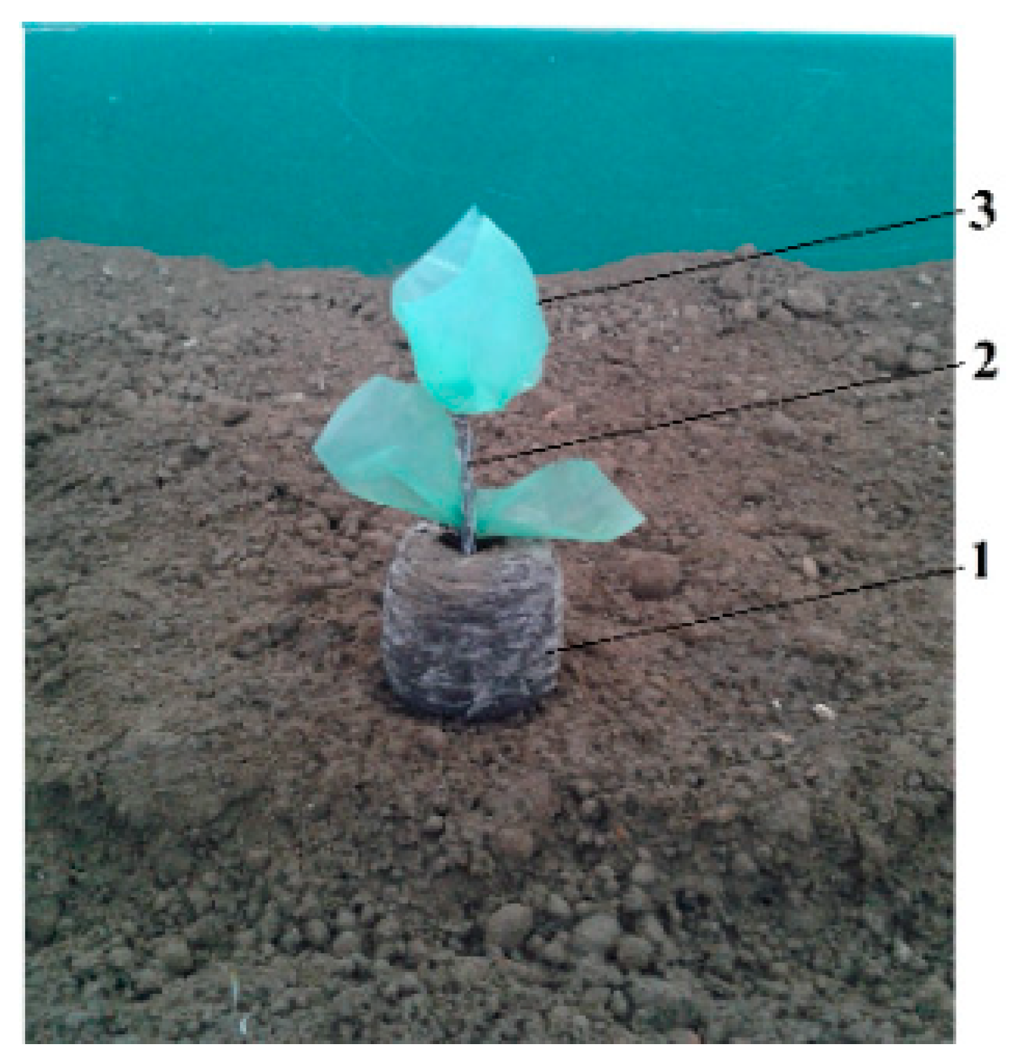
  • Jiffy pellets seedling growing media have been used for decades for a diverse range of plants for the definite advantages of good workability, compatibility with almost all growing trays, high germination rate and shock-free transplanting. They have been utilized for automated transplanting of seedlings into pots or other growing media in greenhouses, but in this technology, they are intended for obtaining seedlings directly into the tray, used then for direct transplanting in the field. In addition to the constancy of dimensional parameters, an essential advantage for the horticultural micro-farm is the elimination of obtaining different recipes for substrate mixture [8,11,12], with all the inherent difficulties: disinfection of the components, dosing, substrate formation; the first stage is more difficult, due to the thermal or chemical operations required, which sometimes also affect the viability of the seedlings [13].
  • The use of the aforementioned mechanically, pneumatically or electrically driven robotic systems for the extraction of seedlings with needles and push forks [7], with L-shaped rotating fingers [8], with clamp-type devices [14], as well as distribution devices with belt-conveyor type with cups [9,15], controlled by an electronic module [16], lead to high qualitative and functional parameters of planting, but with difficulties in operation and maintenance. In the case of the prototype intended for micro-farms in Romania, the solution to eliminate complicated and error-prone seedling extraction and transport systems was the use of exclusively gravitational extraction and multi-stage transport of seedlings with nutrient substrate. Due to the limits to which the substrate can withstand different stresses [17], the verification of Jiffy substrates to transport shocks validates the choice of this simplifying solution.
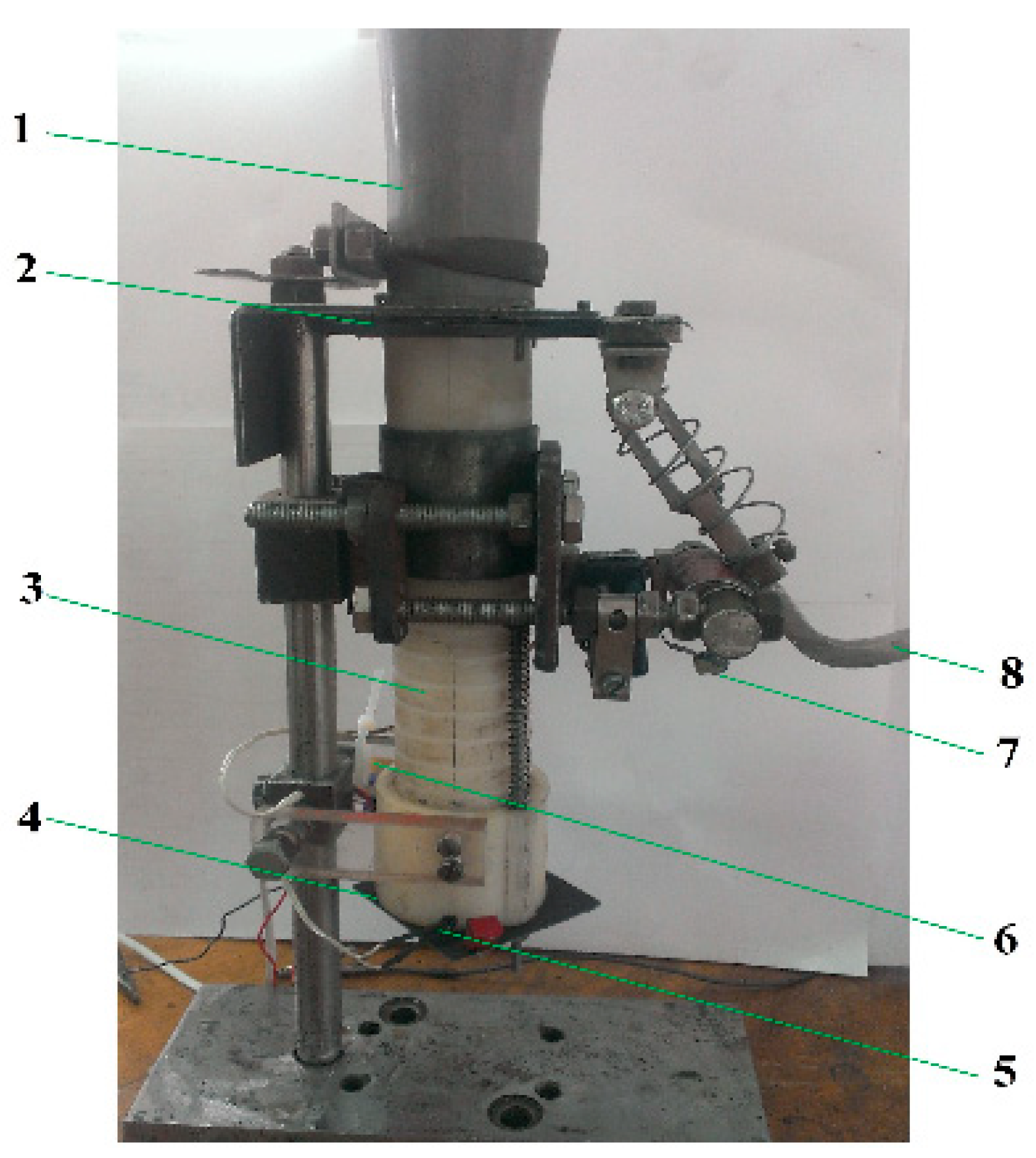
  • Compared to feeding systems from existing high-productivity automatic planters with extraction from universal (Ferrari Growtech, Guidizzolo, Italy) [18] or specialized (Williames Pty Ltd., Warragul, VIC, Australia) [19] trays and transport with different types of conveyors belt types [20,21], the prototype under study comprises a rigid alveolar tray, constructively correlated with the distribution apparatus for simultaneously gravitational discharge of a whole row of seedlings. Thus, intermediate operations performed by third-party systems between the tray and the distribution device are eliminated.
  • Existing automatic planters have either a conventional wheel-linked distribution mechanism [7] or an electronically controlled and electrically driven seedling feeding system, independent of the machine’s movement relative to the ground, based on RTK-GPS technology [22]. In both cases, a slip of the machine’s transport system relative to the ground occurs [23], which implies a variation in the distance between plants per row, greater in the first category. The slippage results in non-zero seedling velocities at soil entry, resulting in altered planting depth [24,25] tilting or damage. The designed transplanter has a planting apparatus drive system allowing the zero-speed seedling’s planting in relation to the soil, correlated with the slipping of the planting wheel [26].
  • Unlike duckbill [27] or dibble [28]-type planters with an external control mechanism, the system designed for the prototype has seedling release flaps from the planting device, controlled by a cam under the action of its own weight force.
The achievement of this integrated technology for planting seedlings comprises five stages, presented in Figure 1:
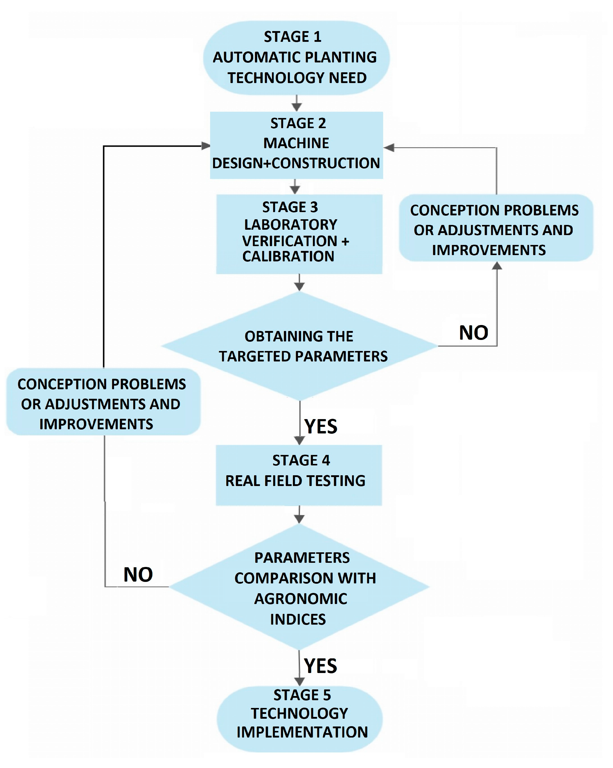
Determining the need for automated seedling planting technology adapted for Romania;
Design and construction of the machine;
Laboratory verification of its operation and preliminary calibration of the main working parameters (working speed and planting time);
Testing under real conditions in the field, with determination of qualitative, energy and economic parameters, for comparison with current agronomic standards;
Technology implementation in practice.
After the design and construction of the prototype, the operating process of the planting machine must be analyzed in terms of two phenomena that take place over interdependent periods of time: the time required to carry out the different operating phases of the feeding system and the time required for the seedling to complete all the stages, from removal from the tray until the entrance into the planting hole. The time intervals involved in the different stages of the planting process are intrinsically linked with the working speed of the machine, which is a defining parameter for machine performance.
These theoretically determined functional characteristics must be verified in practice through calculations and measurements, both at stationary and when operating in the soil bin, to validate the optimum operating values for real operation.
The aim of this paper is to fulfill the second stage of the research:
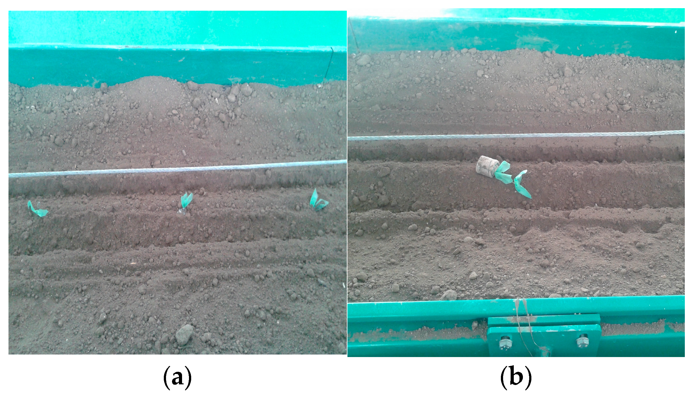
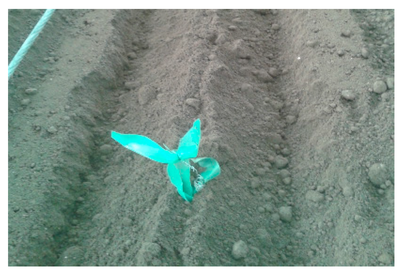
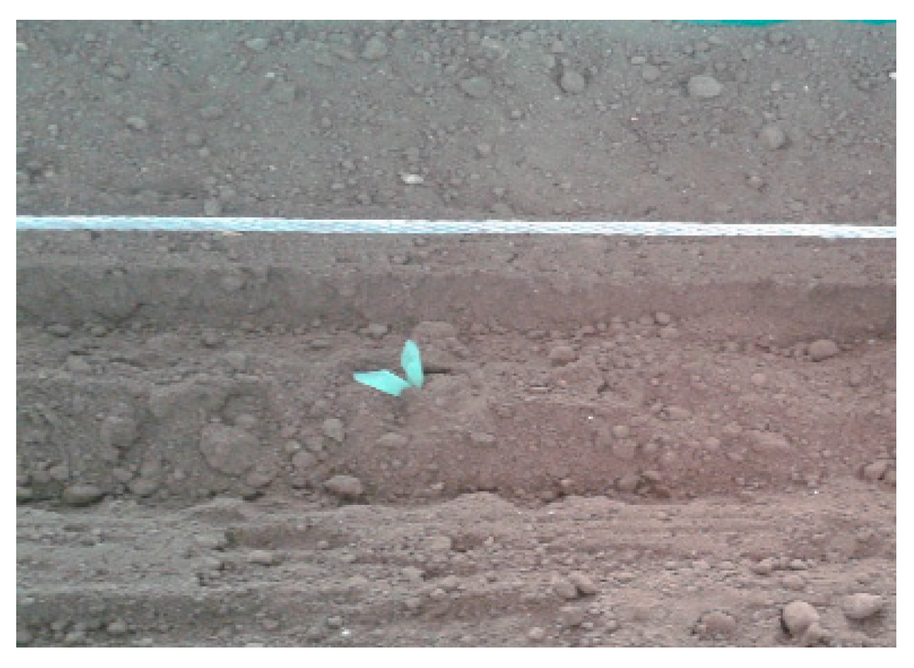
  • Verification of the actual performance of the main operations of the machine: seedling feeding, distribution, insertion and fixing of the seedlings in the soil;
  • To determine the range of feasible working speeds and to check that certain quality and energy indicators are within the agronomic limits.

2. Materials and Methods

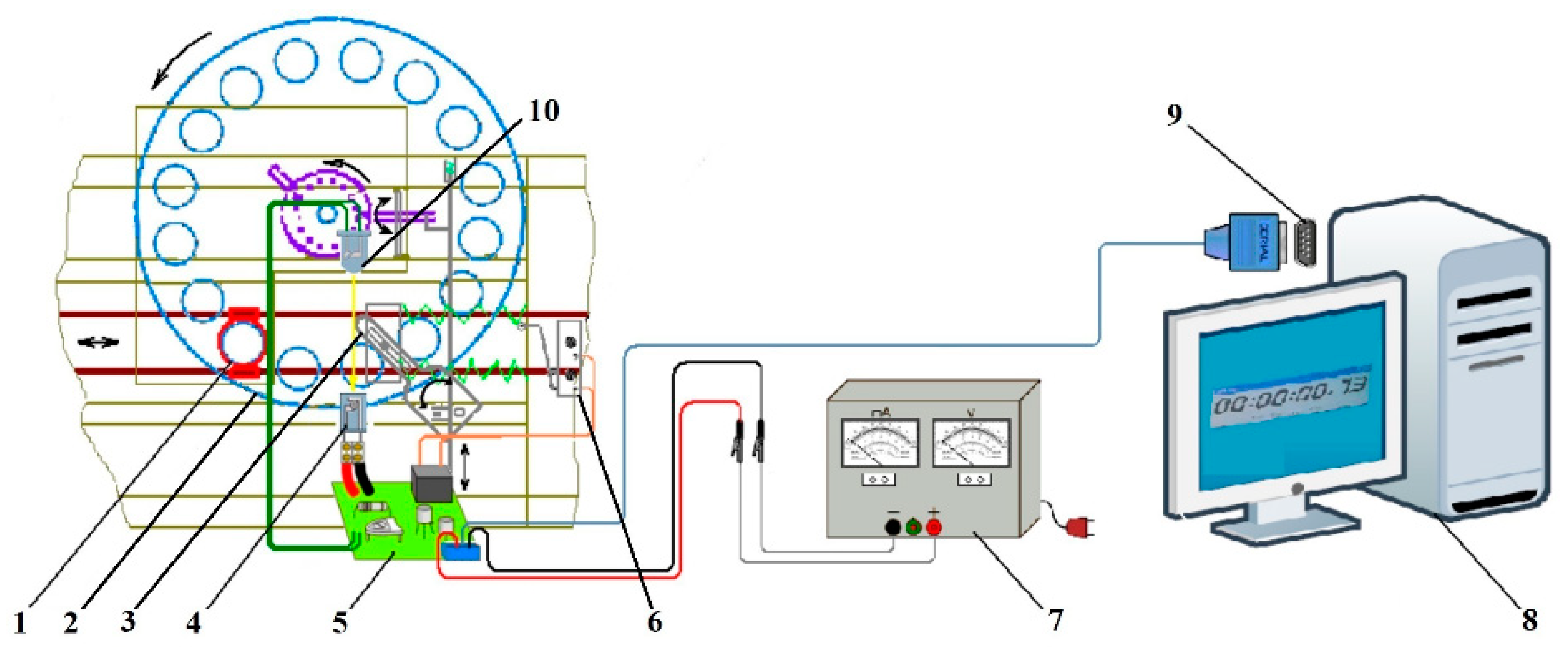
2.1. Seedling Feeding Times

The schematics of the prototype of the planting machine [26], working at speed Vm, which is planting Jiffy nutritive substrate seedlings at distance dp between the plants on a row, in a time tp, is shown in Figure 2.
The machine is shown in the operating position when the feed tube of the planting device (6) is at rest and fed with a seedling from the receiving tube of the distribution apparatus (13). At this moment, when the axis of the planting hole formed in the soil by the spur coincides with the axis of the planting device (6), the control rod (3) actuates the oscillating lever (2) on the portion corresponding to the transport stroke of the AB arc; thus, the sliding rods (5) actuate the planting device (6), which is rolling on the CD curve of the cam guide so the seedling is released when it reaches zero relative speed to the ground (Appendix A). The curve CD equals the fraction of the arc AB corresponding to the transport action (XY arc). The rest of the AB arc corresponds to the pause (BX arc) and return times (AYX arc), respectively; these intervals can be determined according to the position of the control rod on the planter wheel.
Figure 3 shows two combined movements: the distribution apparatus (rotational movement of the distribution apparatus disc with receiving tubes) and the planting device (reciprocating rectilinear movement). The seedling planter travels the corresponding distance dp between two seedlings in a row while the planting device performs two movements:
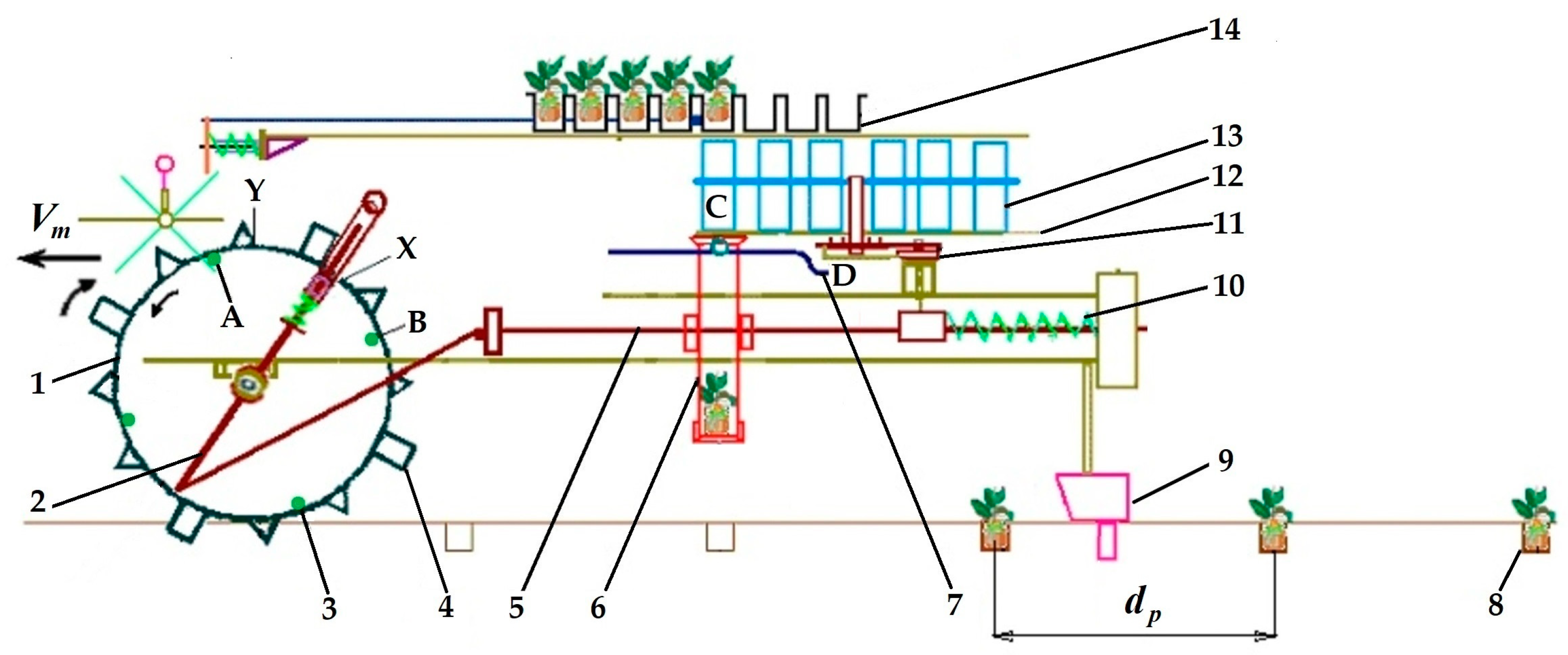
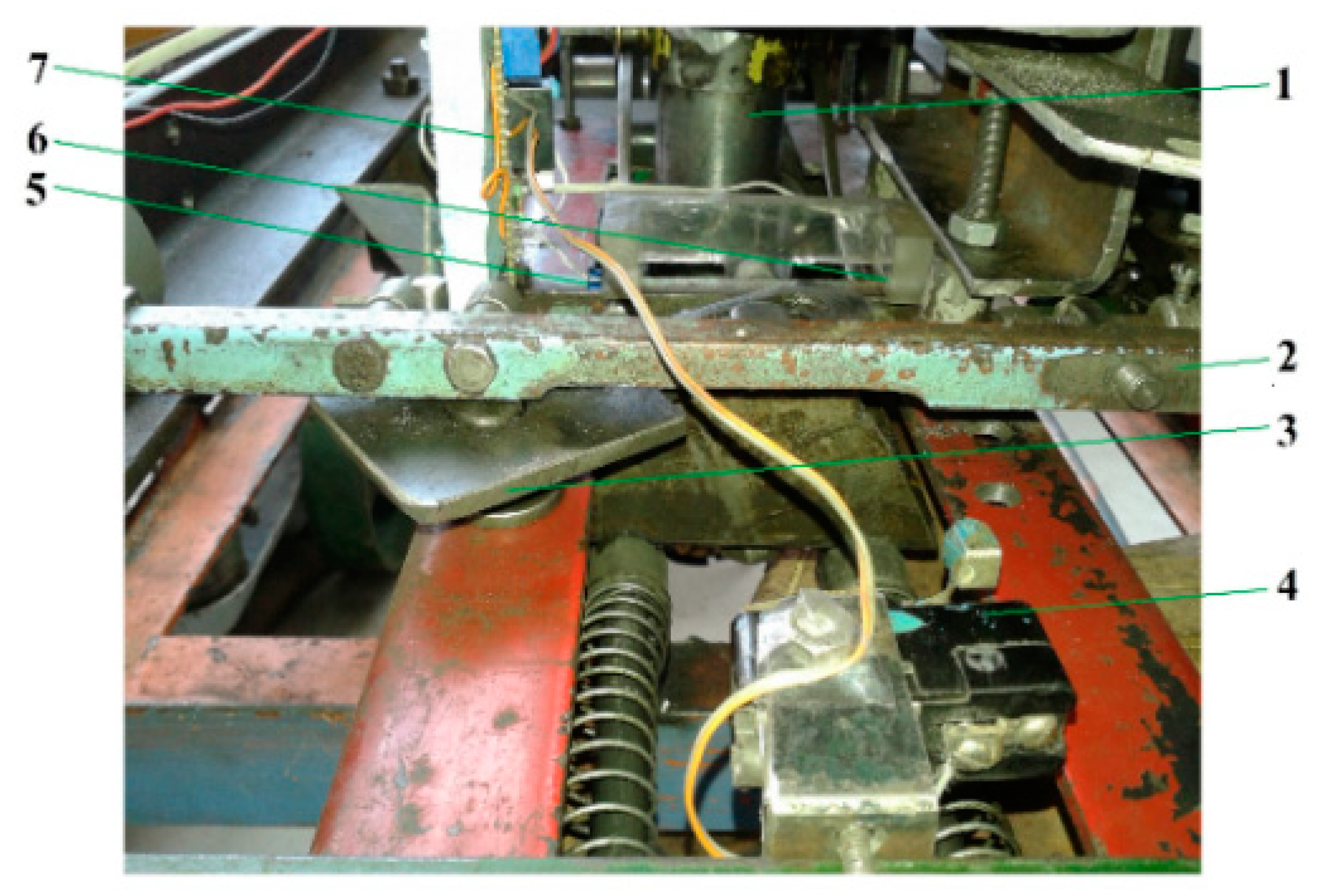
Movement I is the return action of the planting device from the seedling release position to the rest position for feeding (under the slot of the holding-release screen of the distribution apparatus), partially deployed during the return time (YX arc);
Movement II is transporting the seedlings by the planting machine over the same distance during transport time and during the period of initiation of the return movement of the planting device (YA arc).
Between these two movements, the planting device comes to rest in relation to the machine frame (pause time) until the planter wheel control rod comes into contact with the oscillating lever drive profile, initiating the transport stroke (planter wheel XY arc) (Figure 1).
It should be noted that to avoid damaging the seedling, it is necessary that the seedling complete at least part of the gravity fall trajectory from the receiving tube into the planting device tube by the time the seedling transport stroke starts.
To obtain different planting patterns, the planting machine adjustment by mounting an appropriate equidistantly number of spurs on the planting wheel is based on the fact that the pause time determined by the position of the adjustable control rods on the wheel provides the appropriate time interval for correlating the theoretical distance between plants on ra ow with the interval required for the planting device seedling feeding operation.
These considerations indicate that these times overlap at certain stages of the planting device and distribution apparatus operating process, in varying proportions, depending on the working parameters: distance between plants per row and working speeds.
In conclusion, the following times can be defined as being characteristics of the operation of the planting machine described:
Return time trev, in which two separate movements occur: that of the drive rod of the planter wheel, with Vm speed on the YA arc, and the completion of the YX arc by the oscillating driving lever, in the opposite direction relative to the wheel movement;
Pause time t0, corresponding to the control rod peripheral movement on the BX arch, with Vm speed;
Transport time tt corresponds to the movement of the control rod and oscillating lever on the XY arc, with a peripheral velocity equal to the Vm speed.
As a result, the planting time tp is given by the relation:
t p = t r e v + t 0 + t t

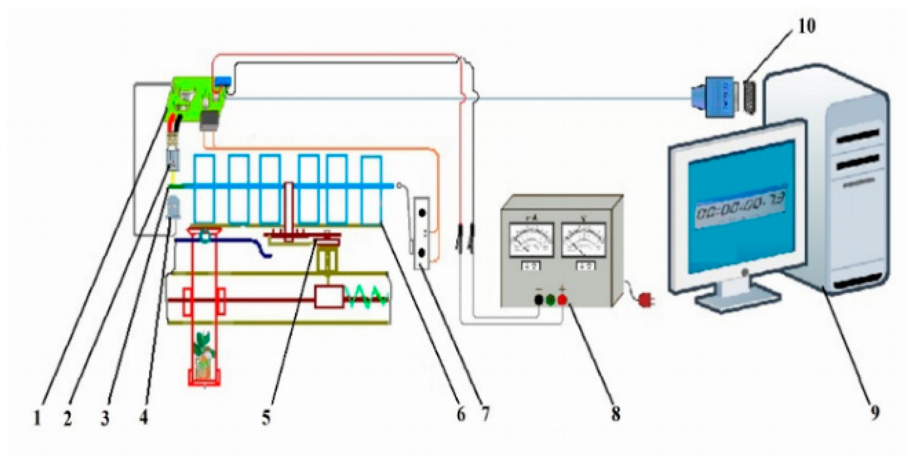
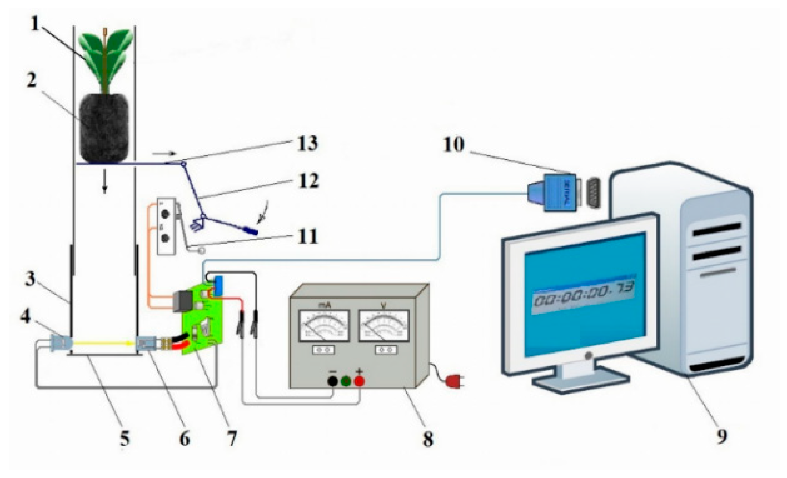
Planting Device Supplying Time

There are two aspects of the seedlings supply to the planting device: the operation of supplying the planting device with a single seedling from the distribution apparatus and, for every four such supplies, the operation of replenishing the distribution apparatus sectors with sets of four seedlings from each row of the tray (Appendix B). Since the second operation overlaps periodically with the first, only this feeding of the planting device is of interest in determining the planting time.
The planting device supplying time tal is given by:
t a l = t p e r + t c d
where:
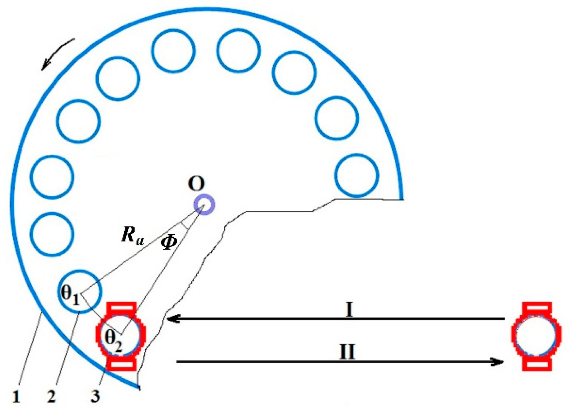
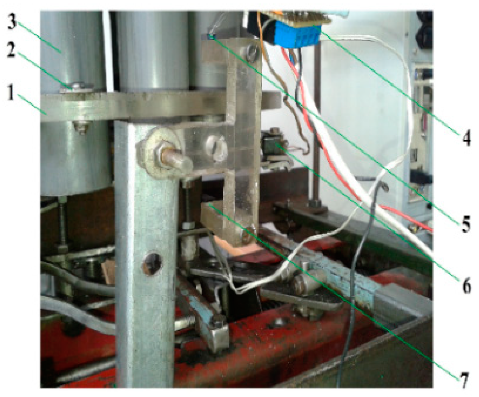
tper—The permutation time of the seedling receiving tube from position θ1 to θ2 (Figure 2);
tcd—Time of gravitational fall of the seedling from the receiving tube into the planting device, s.
The correct supplying condition is as follows: at the end of the permutation stroke of the seedling receiving tube from position θ1 to θ2, the planting device should be at rest position under the slot of the holding-release screen of the distributor; i.e., the return time is lower than the permutation time of the receiving tube, and practically, the planter waits for the gravitational feeding of the seedling during the pause time of the transmission system. The conditions imposed by these factors can be expressed by the relations:
t r e v t p e r
t c d t 0
The return trev and permutation times are determined experimentally by an electronic control block mounted on a planting section operated in stationary conditions.
The gravitational fall time tcd was determined with the same electronic control block mounted on an auxiliary installation [26]. The destination of the auxiliary installation is the measurement of the gravitational feed times for the stages of operation of the planting equipment and for simulating the deformation of the substrates during these operations, thus determining the validity of the choice of such transportation, which is the basis of the simple operation of the machine (Appendix C).
The schematic of the electronic system used to measure the components of planting time is shown in Figure 4.
For these determinations, XNote Stopwatch V 1.63 [29] timing software was used, commanded by the micro-switch of the electronic control block, which also allows the measured times to be recorded.
The return time trev diagram of the measuring installation, presented in Figure 5, is based on the reciprocating rectilinear movement of the planting device. It is determined by measuring the time from the triggering of the micro-contact by the scotch-yoke device to the shut-off of the infrared beam between the infrared LED and the infrared phototransistor by the same part’s lever returns, which has a synchronous movement with the planting device.
The measurement of the permutation time tper was based on the step-by-step movement of the distribution apparatus, operated by a ratchet system, as shown in Figure 6. The start of the timer was triggered by the micro-switch through a receiving tube until the infrared beam between the infrared LED and the infrared phototransistor was interrupted by a shutter mounted on the periphery of the distribution apparatus disc.
The seedling’s fall time was measured by triggering a computer timer with a micro-switch when the lever system was actuated, releasing the seedling simulacrum [3]; the timer was stopped when the substrate passed between the infrared LED and photoreceptor, thus interrupting the IR beam. The auxiliary installation is presented in Figure 7.

2.2. Working Speed

Expressing the pause time t0 as a function of the arc BX leads to:
t 0 = B X ¯ V m V m = B X ¯ t 0
where Vm is working speed, m/s, t0 is pause time, s and the arc length BX, m.
Operating condition (5) allows the determination of the planter’s working speed limit:
V lim B X ¯ t c d
where Vlim is the theoretical maximum working speed of the machine, m/s.
To calculate the actual range of working speeds of the planting machine, bounded by the theoretically determined speed limit, the definitions of the times mentioned in Section 2.1 were corroborated with the experimentally determined values on the said installations and with the measured constructive parameters of the planter wheel equipped with four spurs.
For the last-mentioned measurement, the arcs BX and XY (Figure 2) were determined with the machine at rest and the wheel immobilized immediately after the control rod released the oscillating lever, which reached the end of the return stroke.

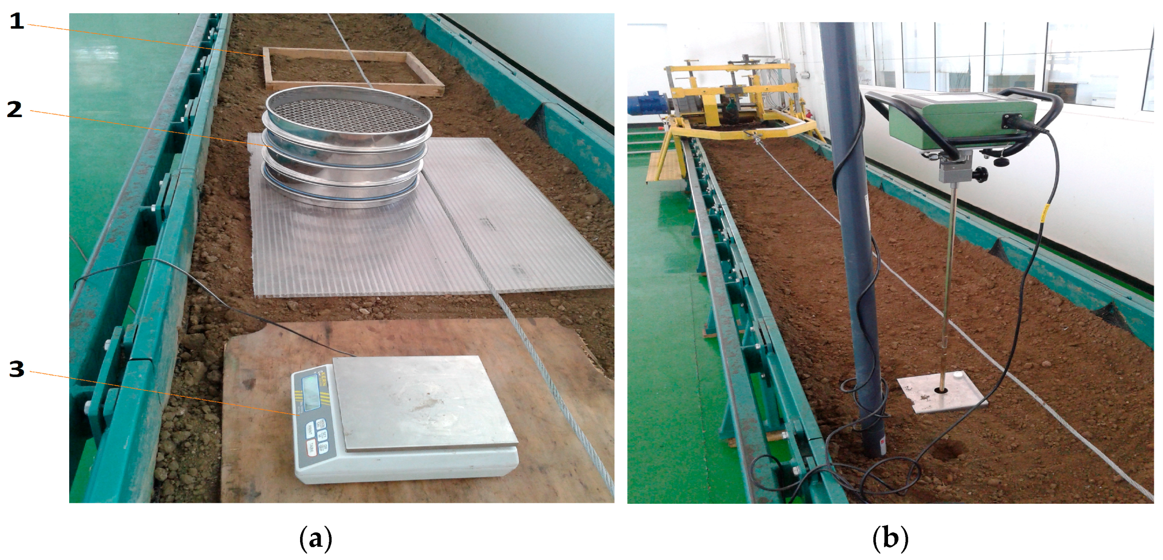
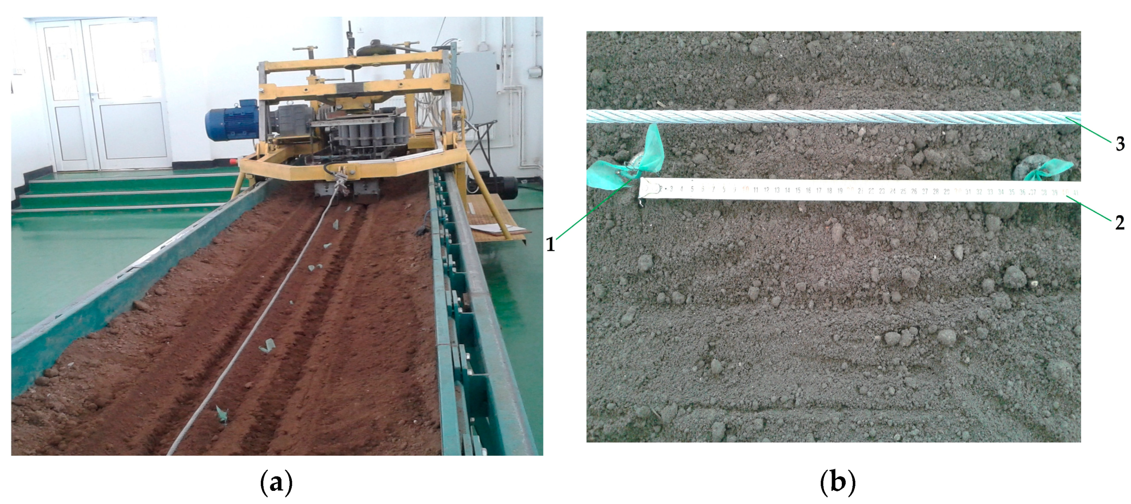
2.3. Soil Bin Studies

The prototype was tested on a soil bin in order to verify the correct functioning of the component systems and to evaluate the constructive, functional and energetic parameters; one of the parameters investigated was the working speed of the equipment. The speed values for which planting of the seedlings is performed properly can be compared with the current values for existing automatic and semi-automatic planting machines; in particular, the maximum value at which proper planting can be performed may provide information regarding the assumptions that led to the theoretical determination of the maximum working speed.
The soil bin shown in Figure 8 [30] was equipped with a trolley on which the tested prototype was mounted. The horizontality and working depth of the planting equipment may be adjusted using screw mechanisms.
The towing cable is coupled to the trolley by two LAUMAS Model SL C3 1000 daN tension load cells, allowing for an average tensile force value to be displayed by a controller.
The rotation speed of the electric motor (5.5 kW and 1000 rpm) may be adjusted by means of a frequency converter (type OMRON Hitachi JX Inverter) to vary the frequency of the supply current between 3 Hz and 50 Hz, allowing the working speed to be modified within wide limits, from 0.1 m/s to 1.55 m/s (0.36…5.58 km/h); it is also possible to control the return movement of the trolley for a new test run on the channel [30].
All these adjustment possibilities will allow the determination of preliminary speeds for prototype testing.
Four indicators were analyzed, with a direct correlation with working speed:
1. A first quality indicator, the relative deviation of the distance between seedlings per row, by measuring the distance between the seedlings on the row’s axis, between the stems points of insertion in the substrate, with a roller; the arithmetic mean was taken:
d p m = i = 1 y d p i y
where:
y = z − 1 is the number of intervals between z planted seedlings.
dp—Distance between plants per row, m.
The relative deviation of the distance between plants from the arithmetic mean Ad was calculated with the usual relation:
A d = i = 1 y ( d p m d p i ) 2 y 1 d p m 100
2. A second qualitative index, the misplanted rate; seedlings that do not survive after planting are in one of the following situations: broken at the stem insertion into the substrate, with the substrate not inserted into the soil, buried in the soil and sloped. Regarding the simulacrum seedlings, these situations are similar, except that the real stem breaking is replaced by stem wire bending. The percentage of misplanted Ms seedlings is:
M s = s w s 100
where:
sw is the number of the misplanted seedlings.
s is the total number of planted seedlings.
3. An energetic indicator, the slip coefficient of the planter wheel; knowing the theoretical value between plants per row dpt (for four spurs on the planter wheel), the wheel slip α was calculated with the relation:
α = d p m d p t d p m 100
4. A qualitative economic exploitation indicator, planting frequency; Fs represents the number of seedlings distributed per second and is determined by the speed of the machine traveling the average distance between seedlings per row:
F s = V m d p m
The agronomic indicators of automatic seedling planting to be met by the four mentioned indicators are taken from the literature and are presented in Table 1.
Due to the relatively small number of seedlings planted along the active length of the soil channel (10 seedlings), three repetitions were performed for each selected speed.

3. Results

3.1. Stationary Collected Data

In order to determine the return time of the planting device and the permutation time of the distribution apparatus, the transplanter prototype was mounted on a suitable stationary stand, which allowed the planter wheel to be driven, with the rotational speed measured by means of a version of the same electronic control block, with the micro-switch triggered by the control rods of the wheel. The rotational speeds of the planter wheel, ranging from 0.47 to 2.38 rev/s, correspond to the calculated working speeds of the transplanter between 0.1 and 0.5 m/s, by the relation:
V = ω R
where:
V is the working transplanter speed, m/s;
ω is the rotational speed, rev/s;
R is the planter wheel radius, m.
Since the planter wheel has four spurs for making planting holes, eight complete wheel rotations are required to make a number of repetitions equal to the number of seedlings contained in a planting tray (32 seedlings).

3.1.1. The Planting Device Return Time Determination

The return times of the planting device for each machine’s working speed and planter wheel rotational speed, determined on installation shown in Figure 9, were processed by calculating the standard deviation from the arithmetic mean (Table 2).

3.1.2. The Distribution Apparatus Permutation Time Determination

The distribution apparatus permutation time was determined, as shown in Figure 10, at the same working and rotational speeds; the measured and processed values are shown in Table 3.

3.1.3. The Gravitational Fall Time Determination

To avoid growing a large number of seedlings for experiments, Jiffy’s substrate seedling simulacrum is used, consisting of a real Jiffy substrate and a wire stem with plastic leaves imitation seedling, presented in Figure 11, made according to the model exposed by Hallonborg, U. [3]. The parameters of a 32-simulacrum set are measured after two-phase watering of the substrate according to the Jiffy manufacturer’s instructions [40] and are presented in Table 4.
The auxiliary system, shown in Figure 12, was adjusted to measure the gravitational fall time of the seedling simulacrum for the distribution apparatus supply stage from the lower end of the receiving tube (13) into the planting device (6) (as shown in Figure 2), where at the bottom end of the tube, a retention system keeps the substrate seedling until the last operation, the gravitational transport to the planting hole in the soil. The exact height of the tube of the planting device (6), which is 228 mm, represents the actual gravitational fall height for this stage of the planting machine supply operation.
The values determined, and the results regarding the standard deviation from the arithmetic mean are shown in Table 5.

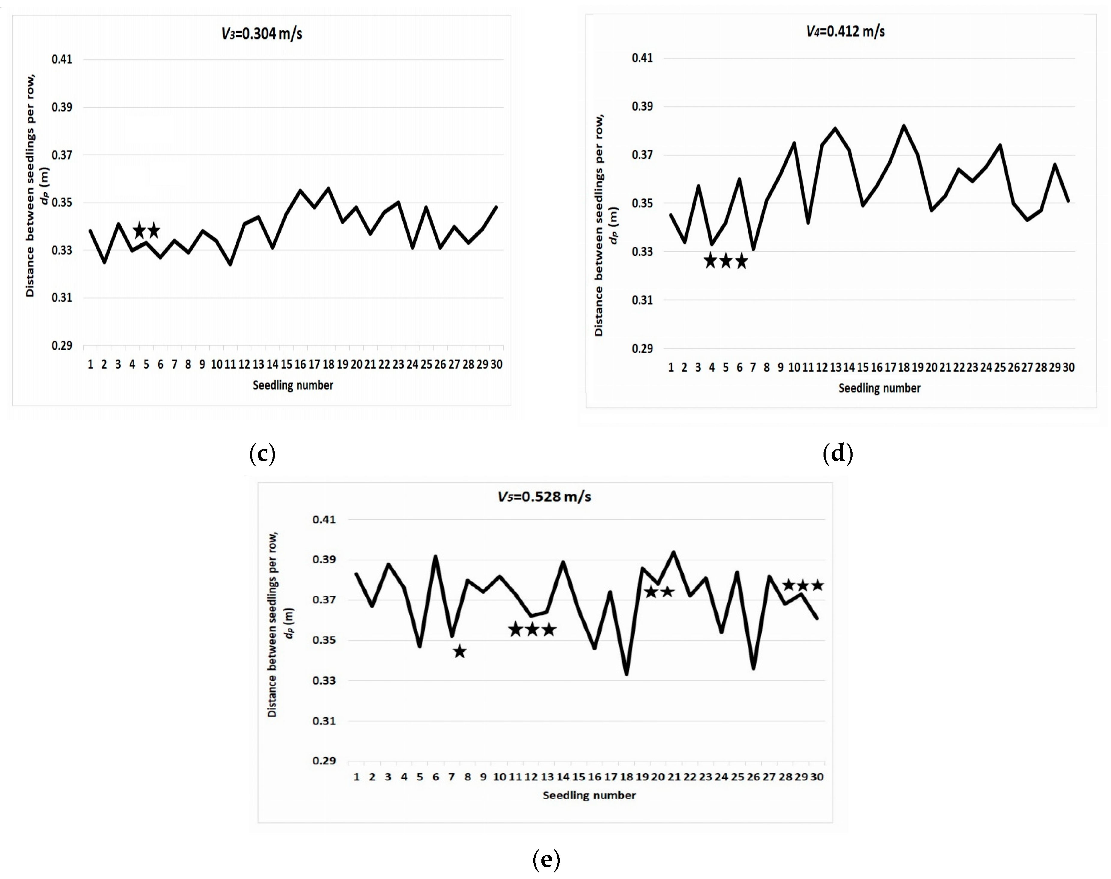
3.2. Soil Bin Test Data

After the soil preparation operations in the bin with the plow attached to the trolley and by processing with the mini-tiller, the degree of soil granulation was analyzed using a metric frame, a set of sieves and a precision balance to determine the percentages of soil components, as shown in Figure 13a. The determinations of the degree of soil compaction and soil moisture at the planting depth of 0–0.150 m were made using the handheld Eijkelkamp cone penetrometer, with humidity electrical conductivity soil sensor ThetaProbe type ML2x (using the software mentioned in Supplementary Materials), as illustrated in Figure 13b.
Following the two types of determinations, the soil in the test bin can be described as a chernozem having a loam-clay texture with 38% clay, 32% silt and 30% sand, with aggregates below 20 mm, moisture content of 19% and compaction of 0.28–0.32 MPa.
During several runs of the soil bin trolley with the planting machine mounted and performed at different speeds without seedling planting, time was measured and divided by the active length of the stand; the speeds obtained are listed in Table 6.
With the machine mounted on the soil bin trolley, with the planting wheel engaged into the soil and with the same adjustment of the fixing skids, at speeds close to those used to determine the planting time components, planting runs were executed (Figure 14). The distances between the planted seedlings simulacra were then measured, as shown in Figure 15; both raw and processed data are presented in Table 7 and Figure 16.

3.3. Wheel Planter Construction Parameters

Measuring the circle arcs of the planting driving wheel (with diameter D = 0.420 m) under the conditions mentioned in Section 2.2 produced the following results:
X Y ¯ = 0.085 ;   B X ¯ = 0.138
where the length of the arc XY, m.
Based on experimental results, it was possible to use the arithmetic mean of the fall time corresponding to transport II from Table 3, i.e.,
tcd = t2 = 0.2590
It therefore follows:
V lim B X ¯ t c d V m 0.533
Thus, for the theoretical maximum limit speed obtained (without slip) of 0.533 m/s (1.918 km/h) and for the theoretical distance between plants per row dpt = 0.321 m, determined for the mentioned planting wheel configuration, the planting time tp can be calculated with the relation:
t p = d p V m
The resulting planting time is greater than or at most equal to the minimum limit value, obtained as follows:
t p t p lim = 0.602
The relationship (1) of the seedling planting time allows the study of the component times.
Thus, the trev return times obtained from the experimental tests (Table 1) have very close values, with arithmetic averages differing by a few tenths of a second, indicating that the recovery springs provide sufficient force to overcome resistances that arise during machine operation at different speeds; the fact that the times are inversely proportional to the five rotational speeds of the planting wheel shows that, at very low speeds, the fraction of the return time corresponding to running the YA arc at the planting wheel speed for a correspondingly longer time changes the composition of the planting time. This influence is less pronounced at high speeds, given the small size of the said arc.
For the calculation of the planting time, the measured return time corresponding to the working speed close to the calculated maximum speed Vlim shall be chosen, i.e., trev = trev5 = 0.3328 s.
The pause time t0, corresponding to the XB arc preceding the operation of the planting machine, is given by the relation:
t 0 = B X ¯ V m = 0.259
The time corresponding to the transportation of the seedling by the planting device on the curve CD, tt, can be deduced by measuring its length or by using the size of the arc XY, equal to CD; thus, it results in the following:
t t = D C ¯ V m = 0.159
So, planting time can be expressed as the sum of its components:
t p min = t r e v + t 0 + t t = 0.750
It can be seen that the value obtained, which is the minimum real planting time of a seedling, calculated with the limited maximum working speed of the machine, follows a relation (17), where the theoretical planting time does not take into account the partial overlapping of some components of the planting and distribution times, an essential element in the machine functioning in different operating modes.

4. Discussion

The data measured for different working speeds provide the possibility of evaluating the constructive and functional factors involved in the indices’ variations in Table 7.
Thus, for the lowest speed V1, difficult planting machine operations occur due to component inertia (oscillating lever-driving rod level, distribution apparatus disc), leading to an increased number of wrongly planted seedlings: tilted and insufficiently fixed (Figure 17a) and displaced, as in Figure 17b and, hence, the results in a higher value of the deviation of the distance between plants per row, even if it is well below the permissible limit. Although the misplanted rate is at the upper acceptable limit, and the wheel slip has a low value, what eliminates V1 working speed is the very low planting frequency, below the accepted range, even for semi-automatic planting machines.
The V2 speed ensures a more constant operation of the distribution system, which has resulted in no planting errors and the lowest deviation of planting distances per row. The low travel speed (about 0.75 km/h) leads to reduced slippage but also to a low planting frequency, below the limit mentioned in the literature.
In the case of the V3 speed, the distribution and planting machine operations are optimal, the only planting fault being the bent seedling simulacrum stem, shown in Figure 18, which would not necessarily compromise planting in a real seedling case. The distance per row deviation, the misplanted rate percentage and the planter wheel slip are within the accepted limits, while the planting frequency, 0.899 s−1 or 53.94 seedlings/minute, exceeds the lower accepted value for the first time. Thus, V3 = 0.304 m/s or 1.094 km/h is the first speed at which the operating parameters specific to an automatic seedling planter are reached.
For the V4 speed, the working parameters are in normal values for the planting process, with the slip index towards the upper allowed limit. The only planting fault is a buried seedling, presented in Figure 19; the planting frequency has a good value for a process with automatic distribution, 1.157 s−1 or 69.42 seedlings per minute, falling well within the range indicated by the literature.
For the V5 speed, the relative deviation index of the distance between seedlings per row is in the normal range and the planting frequency is high, 1.427 s−1 or 85.62 seedlings per minute; however, the exceeded value of the wheel slip and, in particular, the high percentage of planting errors (such as buried and insufficiently fixed seedlings, as in Figure 20a,b) make this working speed not a viable option for machine operation in this prototype design variant.
The resulting soil profile is noticeable with a raised area on the planted row, bordered by two furrows, a phenomenon responsible for some of the planting defects produced.
The relative deviation of the distance between seedlings per row, although generally increasing slightly with working speed, remains, for all five speeds, below the agronomic limit indicated in the literature.
The exception, for V1, with the highest value of these indicators among the five variants, is precisely due to the defective distribution, which led to the change in the distance between the two affected seedlings, visible on the graph in Figure 16a as a sudden variation of large amplitude.
The rate of planting faults has a similar variation, increasing with working speed, with the same exception due to planting faults at V1, where the agronomic upper limit is reached; at V5, however, there is a net overshoot of this indicator due to multiple planting faults, which are not only due to distribution deviations at extreme speeds but also to seedlings poor fixation by winged skids in the soil.
The most influential energy indicator is the slip coefficient of the planting wheel; in practice, its increase with the working speed is the factor that directly determines the identical variation of the distance between plants per row and indirectly the number of misplanted seedlings by altering the interaction of the fixing skids with the soil and the way the planting wheel spurs makes holes in the soil.
Planting frequency is the main indicator that selects the working speeds for future field trials, among those where planting parameters fall within the agronomic limits for automatic transplanters. From the processing of the measured data, the speeds V1 and V2 will not be selected for further testing, even if in V1 tests there was only one indicator at the upper limit, but not exceeded, and there were no misplanted seedlings in V2; the planting frequency for these two speeds is too low, even for manually fed machines.
In the case of speed V5, there is a net overshoot of the slip value, and hence, as pointed out, a high misplanted rate, which also eliminates this speed, even if a very good planting frequency is achieved.
Speeds V3 and V4, with good values of the other indicators, are selected as guideline speeds for field tests precisely because of the planting frequency, acceptable for V3 (according to some cited expert sources, others indicating as a minimum limit a frequency of 1 s−1, i.e., 60 seedlings per minute) and good for V4.

Future Research Directions

Looking at these results, it can be seen that the range of eligible speeds is relatively narrow, and ways need to be found to expand it. While we have shown that it is not feasible from qualitative and economic points of view to choose low speeds, it is logical to eliminate the shortcomings found to achieve higher working speeds.
As shown in relation 15, the theoretical maximum working speed of the machine Vlim = 0.533 m/s and the theoretical maximum planting frequency deduced is 1.66 s−1 or 99.62 seedlings/minute (neglecting both aspects related to the real deployment of some feeding times and wheel slip). The V5 speed has a value close to the limit speed, and obviously, this will be the target working speed if some adjustments or constructive and functional aspects of the prototype are modified.
For this last working speed V5, it should be noted that the process of supplying and transporting the seedlings works correctly; the planting faults are due to the process of introduction and fixing into the soil: incorrectly formed hole, altered (tilted) fixation, and buried seedlings.
Thus, four systems need to be modified to remove or mitigate these shortcomings to achieve higher working speeds in the future.
The first aspect, even if it has mainly occurred at low speeds, the operating deviations due to the high inertia of the distribution apparatus disc, behaving like a flywheel when actuated by the ratchet mechanism, with intermittent movement at low rotational speeds, require its modification or a more efficient immobilization system.
The second issue concerns the shape of the spurs on the wheel (Figure 21a) for forming planting holes, which at high speeds with high slippage tend to form elongated holes, shown in Figure 21b, which can favor the tilting of the seedling in the direction of the row.
The third aspect relates to the fixation of seedlings in the soil by winged fixing skids, presented in Figure 22. It was noted that to standardize the conditions for determining working speeds, the distance and angle of the skid wings are kept constant.
It is obvious that, in addition to changing these parameters according to the soil characteristics in field tests, even at the level of the soil bin where the soil has relatively constant properties, adjustments are necessary because soil flow behavior changes between the skid wings at different working speeds. Thus, because increasing the working speed leads to an increase in the misplanted seedlings number, as shown in Figure 16, it is necessary to increase the distance and decrease the angle between the wings to avoid displacing too vigorously and too much soil, as happened at V5 speed, Figure 20a. In this way, it can be reduced the process of tilting or burial of seedlings already planted in the soil in the fixing process, as shown in Figure 23.
The elongated holes can also favor tilting the seedling in the direction of the row.
The fourth direction is aimed at reducing the wheel slip to the maximum—this factor is the most influential on the behavior of the planting machine. Given that control rods of the distribution system are at the base of some of the anti-slip profiles shown in Figure 21a, the change in their number and profile must be made in accordance with the normal operation of the distribution and, also with the new shape of the spurs, in order not to create variations of wheel adhesion to the ground.
In addition to the prototype testing environment, it should be noted that when testing on the soil bin, there are issues that could interfere with the functioning of the prototype and, therefore, with some of the calculated indicator values. The most important considerations in this situation are as follows:
The slippage is exacerbated due to the soil structure damage after repeated crossings;
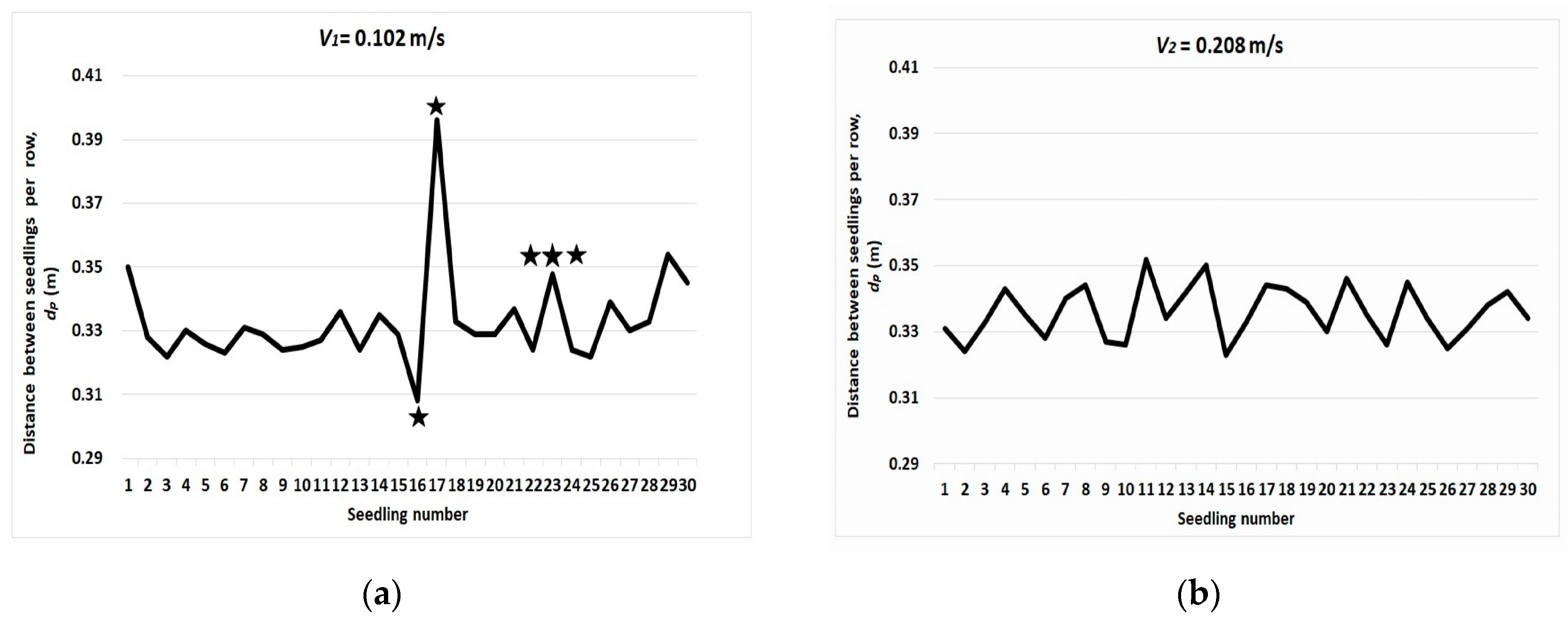
Some events, such as misplanted seedlings, have a higher frequency at the ends of the run (where the soil has more unevenness: moisture, compaction, different grain sizes), observable in the context of a bin run with 10 seedlings planted.
The weight of these influences can only be assessed in actual field tests.

5. Conclusions

The paper presents the test on the soil bin of an automatic seedling planting machine prototype, designed to be attached to a walk-behind tractor, intended for vegetable micro-farms. The work aims at how the transplanter works and the optimal range of speeds for future field tests.
The most important aspects of this research stage are:
  • The results indicate that the chosen speeds, which are below the upper limit of the calculated theoretical working speed, allow for the prototype’s testing, which provides indications of the correctness of the planting operation under near-real conditions.
  • The chosen speeds at which the planting parameters comply with agronomic indicators are comparable to those of existing automatic planting machines.
  • The working speeds suitable for this configuration of the automatic seedling transplanter prototype are within the range given by the speeds V3 and V4, respectively, 0.304 and 0.412 m/s, which have demonstrated the fulfillment of the agronomic indicators imposed by the literature.
  • The prototype achieves seedling planting frequencies of 0.899 and 1.157 s−1, 53.94 and 69.42 seedlings per minute at the mentioned speeds.
At this point, it should be noted that there are no viable working speeds below 0.304 m/s, given the planting frequency towards the lower agronomic limit obtained for V3, which is 0.899 s−1 (nearly 54 seedlings per minute). Still, there are probably working speeds higher than V4 = 0.412 m/s in accordance with the fact that theoretical calculated speed limit (with real planting and distribution times taken into account), given by the relations (16) and (20), is 0.428 m/s.
In order to achieve higher working speeds and thus higher quality and economic indicators, in particular higher planting frequencies, following the analysis of the deficiencies found, directions for improvement of the seedling planter prototype were established for future field trials:
Some low mass inertia components, such as the distribution apparatus disc, should be made to avoid malfunctions at low speeds;
The shape of the spurs should be modified (e.g., by adopting a double-circular arc profile design) to obtain appropriate openings over the whole speed range;
The anti-slip profiles need resizing and reconfiguration to minimize planter wheel slip and improve self-cleaning of soil that tends to stick;
The setting of the fixing skid wings must be correlated with the soil type, moisture content, and working speed, a priority being establishing an appropriate relationship for effective adjustment.

6. Patent

Applicant:
Universitatea de Știinţe Agricole şi Medicină Veterinară “Ion Ionescu de la Brad” [Ro]-Iasi University of Life Sciences (IULS).
Inventor:
Vlahidis Virgil, “Ion Ionescu de la Brad”Iasi University of Life Sciences (IULS), Faculty of Agriculture, Department of Pedotechnics, Romania [RO]
Title:
Equipment for automatically planting seedlings with nutritive pots
Registered by:
OSIM-State Office for Inventions and Trademarks Romania
Priorities:
RO201500134A·2015-02-24
Published as:
RO130295 on 30.03.2022

Supplementary Materials

The following software was accessed and used in this paper: Eijkelkamp Penetrologger, The following supporting information can be downloaded at: https://eijkelkamp-penetroviewer.software.informer.com (accessed on 10 December 2023).

Author Contributions

Writing—original draft preparation, V.V.; review and editing, R.R. and P.-M.C. All authors have read and agreed to the published version of the manuscript.

Funding

This research received no external funding.

Institutional Review Board Statement

Not applicable.

Data Availability Statement

Supplementary data regarding this article will be made available by the corresponding author on reasonable request.

Conflicts of Interest

The authors declare no conflicts of interest.

Appendix A

Avoiding mechanical, pneumatic or hydraulic drive variants with electronic control of the planting device led to the simple design variant of drive from the wheel in contact with the ground. The novelty lies in the lever system (Figure 2), which consists of oscillating levers and sliding rods controlled by the planter wheel that drives the planting device in the two movements shown in Figure 3.
To highlight this aspect, three captures are taken from a video of the planting equipment working on the soil channel, shown in Figure A1.
Figure A1a shows the movement imparted by the planter wheel (1) via the control rod (3) to the oscillating lever (2), which, together with the other components of the lever system, the link bars (4) and the sliding rods (7), drive the planting device (8) in stroke II (Figure 3) on the cam guide (6), with equal speed and opposite direction to the working speed. Sliding rods drive the scotch-yoke mechanism (10) during this time and compress the return springs (12), which will provide the stroke I return movement (Figure 3). The hole (9) is already formed by the spur (5) of the planter wheel and is ahead of the planter; their positions will synchronize at the end of stroke II. The distribution apparatus has a seedling (15) in the receiving tube, supported by the holding-release screen (13) for the future feeding of the planter.
Figure A1b shows the moment when the oscillating lever is towards the end of its rod control action (area A), the planting device has reached the end of stroke II, descends on the downward side of the cam guide (area B), and under the action of its weight, the flaps (16) are opened. The seedling (17) is released and falls into the hole in the ground.
Figure A1. Aspects regarding the operation of the planting device drive system: (a) planting stroke II; (b) Seedling planting time; (c) Operations carried out after stroke I, during pause time t0; (1) planting driving wheel; (2) oscillating lever; (3) control rod; (4) link bars; (5) spur; (6) cam guide; (7) sliding rods; (8) planting device; (9) planting hole; (10) ratchet system; (11) fixing skids; (12) return springs; (13) holding-release screen; (14) receiving tube of the distribution apparatus; (15) seedling ready for feeding; (16) planting device flaps; (17) Seedling in the ground hole; A—oscillating lever-rod control interaction; B—planting device on cam guide downward side; C—released oscillating lever; D—next control rod; E—new seedling for planting device feeding; F—scotch-yoke mechanism position after distribution apparatus permutation movement; G—seedling in the hole in the ground before skids soil tamping.
Agriculture 14 00388 g0a1
At this point, the relative speed of the seedling in the machine’s working direction is 0, the only speed being that in the vertical direction, imparted by the last (third) gravitational transport movement made on the machine.
In Figure A1c, stroke I is completed during the duration of trev under the action of the return springs on the sliding rods. The scotch-yoke mechanism (zone F) ensured the permutation movement of the distribution apparatus, the new seedling (zone E) starting to enter the planting device tube (second gravitational transport movement), all this happening in time pause t0, during which the planting machine will be at rest relative to the machine frame, under the seedling discharge hole of the holding-release screen. In addition, during this period of time, the oscillating lever, having escaped from the action of the previous control rod (zone C), will enter under the action of the next control rod (zone D). The seedling from the ground hole (zone G) enters under the action of the fixing skids (11).
Each variation in the transplanter linear speed due to various factors (micro-leveling, wheel slippage, areas with different soil compaction or friction coefficients) is copied into the movement of the planting device so that the relative speed in the working direction relative to the ground is 0 when the seedling is released into the planting hole.

Appendix B

In order to eliminate intermediate seedling transport systems on the prototype planter, an integrated system consisting of a tray and a distribution apparatus was designed.
The alveolar tray used is constructed to feed the distribution apparatus with groups of gravity-transmitted substrate seedlings in coordination with the operation of the planting device. The tray contains the growing cells arranged in straight rows lengthways and in rows in a circle arc shape on widthways, congruent (in terms of the number and arrangement of the cells) with a whole number of corresponding sectors of the circle of the distribution apparatus disc, as shown in Figure A2.
Figure A2. Seedling feeding system: (a) General view; (b) Alveolar seedling tray on feed table; (1) feed table; (2) alveolar tray; (3) current row of simulacra seedlings; (4) holding-release screen; (5) slot of the holding-release screen; (6) planting device; (7) distribution apparatus; (8) receiving tube of the distribution apparatus; (9) scotch-yoke mechanism; (10) push rod; (11) rod guide; (12) slots of the feed table; (13) simulacra seedling in growing cell.
Agriculture 14 00388 g0a2
The distribution apparatus is of the horizontal rotating disc type with receiving tubes and a holding-release screen with a slot for each seedling to fall into the tube of the planting device. The distribution device is mounted on the shaft of the ratchet mechanism, which drives it in a stepwise permutation movement. The role of this apparatus is to allocate the seedlings, one by one, from the gravitational unloaded row from the alveolar tray to the planting device.
When the last seedling of the previous series falls from the receiving tube (8) through the slot (5) of the holding-release screen (4) into the planting device tube (6), the push rod (10) pushes the alveolar tray (2) with the growing cell with seedling (13) forward with the distance between two rows of trays.
Through the slots of the feed table (1), the current row (3) of the tray is discharged into the receiving tubes (8) of the corresponding sector of the distribution apparatus disc (7) (Figure A2b). The seedlings with the nutrient substrate are stopped at the bottom of the tubes by the holding-release screen and slide on it at the step-by-step rotation of the distribution apparatus, printed by the ratchet device driven by scotch-yoke mechanism (9); when the slot in the hold-release screen is reached, the first seedling in the group drops gravitationally into the planting device tube.
The push rod retracts and is in position by the time the last seedling in the group is delivered to the planting device; one of the control rods of the planter wheel drives the arms of the feeding system and ensures a new forward movement of the tray.
This feeding system allows the seedlings to drop from the growing tray through the distribution unit to the planting device by two successive gravitational falls in a simple and compact design.

Appendix C

The auxiliary installation was designed to reproduce both the deformation of the seedling substrate and the fall times corresponding to the three different stages of gravitational transport [26]. If the fall time tcd is used to determine the feed time for the planting device, the fall times for the other two gravitational transports are used for the calculation of the alveolar tray driving system, respectively, for the dimensioning of the receiving tubes of the distribution apparatus and the cam guide.
The gravitational type of transport simplifies the transmission and seedling supply of the prototype planter but is limited by the degree of deformation that the seedling substrate can withstand, especially at multiple stages of transport and by the dynamics of falling [3], and can be adopted only after checking the seedling deformation of the Jiffy Pellets substrates after successive fall from the real heights in the working process.
The auxiliary installation is dimensionally adjusted for each fall height that reproduces the targeted gravitational transport stage, is loaded with the seedling simulacrum, and is manually operated to trigger the fall; the hatch mimics the sliding on the real supports in operation (feeding table, hold-release screen, planting device flaps).
The fall times are measured using the electronic block mentioned above, and the dimensions after the deformation of the substrates are measured with the caliper. Determinations start with the expansion of Jiffy substrates by watering according to the manufacturer’s instructions; the prefabricated nutrient substrate in its initial state has the following dimensions: a diameter of 36 mm and height of 8 mm. Measure the mass and the lower and upper diameter on a batch of 32 substrates using a scale and a caliper; the values are listed in Table A1.
Table A1. Mean parameters of expanded Jiffy Seedling substrate *.
Lower Diameter
[mm]
Upper Diameter
[mm]
Height
[mm]
Weight (Wet)
[g]
39.86 ± 0.116038.64 ± 0.197341.02 ± 0.120544.36 ± 0.2093
* Data processed by calculating the standard deviation from the arithmetic mean.
After expansion, make the simulacrum seedling by adding the metal stem and plastic leaves. The initial parameters of the simulacra are given in Table A2.
Table A2. Seedling simulacra mean parameters before transport **.
Seedling
Height
[mm]
Stem
Height
[mm]
Substrate
Height
[mm]
Substrate
Diameter
[mm]
Weight
[g]
Foliage
Diameter
[mm]
Leaves Number
[pcs.]
158 ± 0.034580 ± 0.03241.02 ± 0.120539.86 ± 0.116058.6 ± 0.643245 ± 1.8942–4
** Data processed by calculating the standard deviation from the arithmetic mean.
Next, using the installation in Figure 12 for Transport II from the planting device tube and the variants for Transports I and III, shown in Figure A3, the substrate deformations corresponding to the parameters: substrate lower diameter and substrate height are determined; the first parameter serves for the actual dimensioning of the drop tubes, while the second provides information on the degree of deformation after successive transports. The values are presented in Table A3.
Figure A3. Auxiliary installation for gravity transport simulation. (a) Height adjustment for Transport II; (b) height adjustment for Transport III.
Agriculture 14 00388 g0a3
Table A3. Seedling simulacra parameters after transport stages ***.
Initial
Values
Transport I
h1 = 185 mm
Transport II
h2 = 228 mm
Transport III
h3 = 80 mm
Lower
Diameter
[mm]
Height
[mm]
Lower
Diameter
[mm]
Height
[mm]
Lower
Diameter
[mm]
Height
[mm]
Lower
Diameter
[mm]
Height
[mm]
39.86 ± 0.1160 41.02 ± 0.120541.11 ± 0.237440.28 ± 0.141141.53 ± 0.112938.88 ± 0.156942.80 ± 0.103937.10 ± 0.1767
*** Data processed by calculating the standard deviation from the arithmetic mean.
The mass of the simulacra was constant during the short time of the determinations; there were also no variations regarding stem and leaf simulacrums. The variations of the measured parameters are relatively small, and the most important aspect is that the seedling simulacrums maintained their integrity, which demonstrates the viability of the chosen gravity transport system.

Appendix D

Table A4. Planting device return time.
Return
Time
Speed
Rotational/Working
trev1
(s)
trev2
(s)
trev3
(s)
trev4
(s)
trev5
(s)
ω1 = 0.47 rev/s
V1 = 0.1 m/s
ω2 = 0.95 rev/s
V2 = 0.2 m/s
ω3 = 1.42 rev/s
V3 = 0.3 m/s
ω4 = 1.90 rev/s
V4 = 0.4 m/s
ω5 = 2.38 rev/s
V5 = 0.5 m/s
10.370.360.350.350.34
20.370.320.350.330.34
30.350.380.370.350.36
40.340.380.320.330.35
50.370.320.350.340.32
60.350.360.340.350.33
70.330.350.340.340.32
80.370.370.330.340.31
90.360.340.330.340.35
100.350.330.340.330.34
110.350.330.360.360.35
120.340.320.350.340.33
130.370.350.340.330.32
140.370.340.350.330.32
150.340.370.360.340.31
160.360.330.350.330.32
170.330.370.340.330.35
180.320.330.360.350.34
190.340.350.350.350.32
200.330.370.350.330.31
210.360.330.360.330.32
220.330.360.370.350.35
230.340.330.330.350.33
240.350.340.360.340.34
250.350.380.350.360.36
260.370.360.360.340.35
270.360.380.330.320.34
280.350.330.360.340.33
290.360.350.350.330.31
300.340.330.330.340.32
310.360.380.350.350.32
320.340.350.350.360.35
X = x ¯ ± σ x ¯ 0.3506 ± 0.00250.3496 ± 0.0035 0.3478 ± 0.00210.3406 ± 0.00180.3328 ± 0.0027
Table A5. Distribution apparatus permutation time.
Permutation
Time
Speed
Rotational/Working
tper1
(s)
tper2
(s)
tper3
(s)
tper4
(s)
tper5
(s)
ω1 = 0.47 rev/s
V1 =0.1 m/s
ω2 = 0.95 rev/s
V2 =0.2 m/s
ω3 = 1.42 rev/s
V3 =0.3 m/s
ω4 = 1.90 rev/s
V4 = 0.4 m/s
ω5 = 2.38 rev/s
V5 = 0.5 m/s
10.750.720.780.780.74
20.750.740.830.730.80
30.810.770.760.810.79
40.740.740.750.710.80
50.790.770.730.790.79
60.740.710.790.750.76
70.780.770.770.830.71
80.740.800.720.790.81
90.780.760.770.830.79
100.810.820.750.720.77
110.830.790.830.830.80
120.820.770.780.820.76
130.750.820.840.710.75
140.770.770.750.810.73
150.770.750.830.740.76
160.800.800.790.740.82
170.820.800.810.780.74
180.810.750.780.760.79
190.830.810.710.730.76
200.790.810.820.800.81
210.770.770.730.810.76
220.750.820.810.790.79
230.750.800.750.810.79
240.730.780.830.700.81
250.800.790.740.790.71
260.760.800.840.780.81
270.800.760.730.780.76
280.740.770.800.770.72
290.800.800.740.810.75
300.790.780.780.700.75
310.770.750.760.780.81
320.770.750.750.770.76
X = x ¯ ± σ x ¯ 0.7784 ± 0.00520.7762 ± 0.00500.7765 ± 0.00670.7734 ± 0.00700.7718 ± 0.0055

References

  1. Huang, B.K.; Ai, F. Air-pruned transplant production system for fully automated transplanting. Acta Hortic. 1992, 319, 523–528. [Google Scholar] [CrossRef]
  2. Gao, J.H.; Huang, B.K. Computer-Controlled Transplanting of Air-Pruned Seedlings/Plugs. SNA Res. Conf. 1993, 38, 229–234. [Google Scholar]
  3. Hallonborg, U. Wobbling in Pneumatic Systems for Transporting Seedlings. J. For. Eng. 1998, 9, 7–14. [Google Scholar] [CrossRef]
  4. Zhang, N.; Zhang, G.; Liu, H.; Liu, W.; Wei, J.; Tang, N. Design of and Experiment on Open-and-Close Seedling Pick-Up Manipulator with Four Fingers. Agriculture 2022, 12, 1776. [Google Scholar] [CrossRef]
  5. Jorg, O.J.; Sportelli, M.; Fontanelli, M.; Frasconi, C.; Raffaelli, M.; Fantoni, G. Design, Development and Testing of Feeding Grippers for Vegetable Plug Transplanters. AgriEngineering 2021, 3, 669–680. [Google Scholar] [CrossRef]
  6. Tsuga, K. Development of fully automatic vegetable transplanter. Jarq-Jpn. Agric. Res. Q. 2000, 34, 21–28. [Google Scholar]
  7. Ye, B.L.; Li, L.; Yu, G.H.; Liu, A.; Cai, D. Design and test on cam mechanism of seedling pick-up arm for vegetable transplanter for pot seedling. Trans. CSAE 2014, 30, 21–29. [Google Scholar]
  8. Khadatkar, A.; Mathur, S.M.; Dubey, K.; BhusanaBabu, V. Development of embedded automatic transplanting system in seedling transplanters for precision agriculture. Artif. Intell. Agric. 2021, 5, 175–184. [Google Scholar] [CrossRef]
  9. Jin, X.; Yuan, Y.; Ji, J.; Zhao, K.; Li, M.; Chen, K. Design and implementation of anti-leakage planting system for transplanting machine based on fuzzy information. Comput. Electron. Agric. 2020, 169, 105204. [Google Scholar] [CrossRef]
  10. Yang, Q.; Huang, G.; Shi, X.; He, M.; Ahmad, I.; Zhao, X.; Addy, M. Design of a control system for a mini-automatic transplanting machine of plug seedling. Comput. Electron. Agric. 2020, 169, 105226. [Google Scholar] [CrossRef]
  11. Jin, X.; Li, D.Y.; Ma, H.; Ji, J.T.; Zhao, K.X.; Pang, J. Development of single row automatic transplanting device for potted vegetable seedlings. Int. J. Agric. Biol. Eng. 2018, 11, 67–75. [Google Scholar] [CrossRef]
  12. Han, L.; Mo, M.; Gao, Y.; Ma, H.; Xiang, D.; Ma, G.; Mao, H. Effects of New Compounds into Substrates on Seedling Qualities for Efficient Transplanting. Agronomy 2022, 12, 983. [Google Scholar] [CrossRef]
  13. Parladé, J.; Pera, J.; Álvarez, I.F.; Bouchard, D.; Généré, B.; Le Tacon, F. Effect of inoculation and substrate disinfection method on rooting and ectomycorrhiza formation of Douglas fir cuttings. Ann. For. Sci. 1999, 56, 35–40. [Google Scholar] [CrossRef]
  14. Iqbal, M.Z.; Islam, M.N.; Ali, M.; Kabir, M.S.N.; Park, T.; Kang, T.G.; Park, K.-S.; Chung, S.-O. Kinematic analysis of a hopper-type dibbling mechanism for a 2.6 kW two-row pepper transplanter. J. Mech. Sci. Technol. 2021, 35, 2605–2614. [Google Scholar] [CrossRef]
  15. Han, C.; Hu, X.; Zhang, J.; You, J.; Li, H. Design and testing of the mechanical picking function of a high-speed seedling auto-transplanter. Artif. Intell. Agric. 2021, 5, 64–71. [Google Scholar] [CrossRef]
  16. Jin, X.; Li, M.; Li, D.; Ji, J.; Pang, J.; Wang, J.; Peng, L. Development of automatic conveying system for vegetable seedlings. EURASIP J. Wirel. Commun. Netw. 2018, 2018, 178. [Google Scholar] [CrossRef]
  17. Zeng, F.; Cui, J.; Li, X.; Bai, H. Establishment of the Interaction Simulation Model between Plug Seedlings and Soil. Agronomy 2024, 14, 4. [Google Scholar] [CrossRef]
  18. Ferrari Growtech. Available online: https://ferrarigrowtech.com/en/tray-transplanters/8-futura-automated-transplanter.html. (accessed on 10 February 2024).
  19. Williames Pty Ltd. Available online: http://www.williames.com/nursery-machinery/williames-trays-flats/ (accessed on 10 February 2024).
  20. Wen, Y.; Zhang, J.; Tian, J.; Duan, D.; Zhang, Y.; Tan, Y.; Yuan, T.; Li, X. Design of a traction double-row fully automatic transplanter for vegetable plug seedlings. Comput. Electron. Agric. 2021, 182, 106017. [Google Scholar] [CrossRef]
  21. Han, L.; Mao, H.; Hu, J.; Kumi, F. Development of a Riding-Type Fully Automatic Transplanter for Vegetable Plug Seedlings. Span. J. Agric. Res. 2019, 17, e0205. [Google Scholar] [CrossRef]
  22. Sun, H.; Slaughter, D.C.; Ruiz, M.P.; Gliever, C.; Upadhyaya, S.K.; Smith, R.F. RTK GPS mapping of transplanted row crops. Comput. Electron. Agric. 2010, 71, 32–37. [Google Scholar] [CrossRef]
  23. Pérez-Ruiz, M.; Slaughter, D.C. Development of a precision 3-row synchronised transplanter. Biosyst. Eng. 2021, 206, 67–78. [Google Scholar] [CrossRef]
  24. Reza, M.N.; Ali, M.; Habineza, E.; Kabir, M.S.; Kabir, M.S.N.; Lim, S.-J.; Choi, I.-S.; Chung, S.-O. Analysis of operating speed and power consumption of a gear-driven rotary planting mechanism for a 12-kW six-row self-propelled onion transplanter. Span. J. Agric. Res. 2023, 21, e0207. [Google Scholar] [CrossRef]
  25. Manilla, R.D.; Shaw, L.N. A high-speed dibbling transplanter. Trans. ASAE 1987, 30, 904–908. [Google Scholar] [CrossRef]
  26. Vlahidis, V. Contributions to Improving the Seedling Planting Process. Ph.D. Thesis, “Gh.Asachi” Technical University Iași, Faculty of Mechanics, Specialisation Mechanical Engineering, Iași, Romania, 2014. [Google Scholar]
  27. He, T.; Li, H.; Shi, S.; Liu, X.; Liu, H.; Shi, Y.; Jiao, W.; Zhou, J. Preliminary Results Detailing the Effect of the Cultivation System of Mulched Ridge with Double Row on Solanaceous Vegetables Obtained by Using the 2ZBX-2A Vegetable Transplanter. Appl. Sci. 2023, 13, 1092. [Google Scholar] [CrossRef]
  28. Wang, Y.; He, Z.; Wang, J.; Wu, C.; Yu, G.; Tang, Y. Experiment on transplanting performance of automatic vegetable pot seedling transplanter for dry land. Trans. Chin. Soc. Agric. Eng. 2018, 34, 19–25. [Google Scholar] [CrossRef]
  29. Xnote Stopwatch V 1.63. Available online: http://www.xnotestopwatch.com/download.html (accessed on 11 December 2023).
  30. Țenu, I.; Roșca, R.; Cârlescu, P.; Vlahidis, V. Laboratory Stand for Impact Study Agricultural Traffic and Technological Works on Soil Physical Properties; Iasi Polytechnic Institute Bulletin, Machine Constructions Section: Iași, Romania, 2012; Volume LVIII (LXII), pp. 255–262. [Google Scholar]
  31. Stubbs, S.; Colton, J. The Design of a Mechanized Onion Transplanter for Bangladesh with Functional Testing. Agriculture 2022, 12, 1790. [Google Scholar] [CrossRef]
  32. Khadatkar, A.; Mathur, S.M.; Dubey, K.; Magar, A.P. Automatic Ejection of Plug-type Seedlings using Embedded System for use in Automatic Vegetable Transplanter. J. Sci. Ind. Res. 2021, 80, 1042–1048. [Google Scholar] [CrossRef]
  33. Prasanna Kumar, G.V.; Raheman, H. Development of a walk-behind type hand tractor powered vegetable transplanter for paper pot seedlings. Biosyst. Eng. 2011, 110, 189–197. [Google Scholar] [CrossRef]
  34. Brewer, H.L. Experimental Automatic Feeder for Seedling Transplanter. Appl. Eng. Agric. 1988, 4, 24–29. [Google Scholar] [CrossRef]
  35. Liu, J.; Zhao, S.; Li, N.; Faheem, M.; Zhou, T.; Cai, W.; Zhao, M.; Zhu, X.; Li, P. Development and field test of an autonomous strawberry plug seeding transplanter for use in elevated cultivation. Appl. Eng. Agric. 2019, 35, 1067–1078. [Google Scholar] [CrossRef]
  36. Yang, L.; He, X.T.; Cui, T.; Zhang, D.X.; Shi, S.; Zhang, R.; Wang, M. Development of mechatronic driving system for seed meters equipped on conventional precision corn planter. Int. J. Agric. Biol. Eng. 2015, 8, 1–9. [Google Scholar] [CrossRef]
  37. Iqbal, M.Z.; Islam, M.N.; Chowdhury, M.; Islam, S.; Park, T.; Kim, Y.-J.; Chung, S.-O. Working Speed Analysis of the Gear-Driven Dibbling Mechanism of a 2.6 kW Walking-Type Automatic Pepper Transplanter. Machines 2021, 9, 6. [Google Scholar] [CrossRef]
  38. Garibaldi-Márquez, F.; Martínez-Reyes, E.; García-Hernández, R.V.; Galindo-Reyes, M.A. Planter to distribute seeds in four-row beds and harvest rainwater. Ing. Agrícola Y Biosist. 2020, 12, 21–40. [Google Scholar] [CrossRef]
  39. Wen, Y.; Zhang, L.; Huang, X.; Yuan, T.; Zhang, J.; Tan, Y.; Feng, Z. Design of and Experiment with Seedling Selection System for Automatic Transplanter for Vegetable Plug Seedlings. Agronomy 2021, 11, 2031. [Google Scholar] [CrossRef]
  40. Jiffy Pellets Products. Available online: https://jiffygroup.com/products/jiffy-pellets/#jiffypellets (accessed on 3 January 2024).
Figure 1. The stages of the automatic seedling planting technology development.
Agriculture 14 00388 g001
Figure 2. Schematics regarding the constructive and functional parameters of the automatic transplanter [26]: (1) planting driving wheel; (2) oscillating lever; (3) control rod; (4) spur; (5) sliding rods; (6) planting device; (7) cam guide; (8) seedling; (9) fixed winged skids; (10) return springs; (11) ratchet system; (12) holding-release screen; (13) receiving tube of the distribution apparatus; (14) seedlings tray; A—position of the control rod at the previous planting stroke; B—position of the control rod at the next planting stroke; C—position of the planting device on the cam guide at the planting stroke start; D—position of the planting device on the cam guide at the end of the planting stroke; X—oscillating lever position at the start of the planting stroke; Y—oscillating lever position at the end of the planting stroke; dp—distance between plants on the row; BX and XY circle arcs.
Agriculture 14 00388 g002
Figure 3. Aspects of distribution and planting movements: (1) distribution apparatus disc; (2) receiving tube; (3) planting device; I—return stroke; II—planting stroke; Ra—the radius of the distribution apparatus at the centers of the receiving tubes Φ—the angle at the center corresponding to the arc θ1θ2 described by the distribution apparatus disc for supplying a seedling to the planting device.
Agriculture 14 00388 g003
Figure 4. Electronic control block: R1—2 kΩ electrical resistance; R2—8 kΩ electrical resistance; R3—0.560 kΩ electrical resistance; R4—2 kΩ electrical resistance; LED 1—light in infrared emission; LED 2—light in infrared phototransistor; MSW—micro-contact; TC—control transistor; ND1—normally open contact; ND2—normally open contact; S—solenoid; PS9—PC nine-pin serial port.
Agriculture 14 00388 g004
Figure 5. Installation diagram for measuring the return time of the planting device: (1) planting device; (2) distribution apparatus; (3) scotch-yoke device; (4) infrared phototransistor; (5) data acquisition board; (6) micro-switch; (7) DC power supply; (8) computer; (9) serial port; (10) infrared LED.
Agriculture 14 00388 g005
Figure 6. Installation diagram for measuring the distribution device permutation time: (1) data acquisition board; (2) infrared phototransistor; (3) shutter; (4) infrared LED; (5) ratchet system; (6) distribution apparatus; (7) micro-switch; (8) DC power supply; (9) computer; (10) serial port.
Agriculture 14 00388 g006
Figure 7. Test rig for measuring fall times for gravitational transport and substrate deformation: (1) seedling simulacrum foliage; (2) seedling substrate; (3) guide tube; (4) infrared LED; (5) impact surface; (6) infrared phototransistor; (7) data acquisition board; (8) DC power supply; (9) computer; (10) serial port; (11) micro-switch; (12) lever system; (13) trap door; ↓—the dropping direction of the seedling simulacrum; →—the trap door direction of opening; ↷—the lever system direction of rotation.
Agriculture 14 00388 g007
Figure 8. Soil bin test rig: (1) soil channel frame; (2) planting machine; (3) trolley; (4) control panel; (5) sensors for measuring the pulling force; (6) electric motor for driving the trolley; (7) pulling cable; (8) vertical loading mechanism on the roller; (9) vertical loading mechanism on the wheel; (10) mechanism for vertical adjustment of the machine’s clamping support.
Agriculture 14 00388 g008
Figure 9. Installation configuration used to determine the return time of the planting device: (1) planting device; (2) oscillating sliding bar; (3) oscillating scotch-yoke lever; (4) micro-switch; (5) infrared LED; (6) infrared phototransistor; (7) data acquisition board.
Agriculture 14 00388 g009
Figure 10. Installation configuration used to determine the distribution apparatus permutation time: (1) distribution apparatus disc; (2) receiving tube; (3) shutter; (4) acquisition data board; (5) Infrared LED; (6) micro-switch; (7) infrared phototransistor.
Agriculture 14 00388 g010
Figure 11. Substrate seedling simulacra: 1. plug; 2. stem; 3. leaves.
Agriculture 14 00388 g011
Figure 12. Auxiliary installation for seedling’s fall time determination adjusted for the height of 228 mm: (1) receiving tube; (2) trapdoor; (3) planting device tube; (4) plate for stopping the seedling; (5) infrared phototransistor; (6) electronic device (with Infrared LED); (7) micro-switch; (8) lever.
Agriculture 14 00388 g012
Figure 13. Aspects of the determinations of soil characteristics in the test bin: (a) soil particle size analysis: (1) metric scale; (2) soil sieves set; (3) precision balance; (b) penetration resistance and soil moisture determinations are cited.
Agriculture 14 00388 g013
Figure 14. Planting machine run in the soil bin (video capture).
Agriculture 14 00388 g014
Figure 15. Seedlings simulacra in the soil bin: (a) planted in a row at the run end; (b) measuring the distance between seedlings: (1) planted seedling; (2) measuring tape; (3) towing cable.
Agriculture 14 00388 g015
Figure 16. Distances measured between seedlings on the row. (a) Results for V1; (b) results for V2; (c) results for V3; (d) results for V4; (e) results for V5. Errors due to: ★ distribution apparatus blockages, ★★ unfixed seedling, ★★★ wrongly planted seedling.
Agriculture 14 00388 g016aAgriculture 14 00388 g016b
Figure 17. Planted seedlings at V1 working speed. (a) Tilted and insufficiently fixed seedlings; (b) displaced seedlings.
Agriculture 14 00388 g017
Figure 18. Seedling simulacrum with a bent wire stem.
Agriculture 14 00388 g018
Figure 19. Buried seedling simulacrum.
Agriculture 14 00388 g019
Figure 20. Transplanter with V5 working speed; (a) raised planted row with buried seedlings; (b) tilted and insufficiently fixed seedling.
Agriculture 14 00388 g020
Figure 21. Influence of the spur’s shape on the planting hole profile. (a) Detail of the planter wheel: (1) spur; (2) fixing and adjusting screw; (3) anti-slip profile; (4) threaded adjusting rod; (5) control rod. (b) Elongated planting hole.
Agriculture 14 00388 g021
Figure 22. Winged fixing skids-rear view: (1) support; (2) active surface of the skid; (3) skid wing; (4) rotating hub for adjusting the distance between the skid wings: (5) the angle made by the wing with the forward direction; (6) device for adjusting the wing inclination angle with the direction of travel.
Agriculture 14 00388 g022
Figure 23. Tilted and partially buried seedlings in the winged skid-fixing process.
Agriculture 14 00388 g023
Table 1. Agronomic requirements for seedling planting.
Agronomic
Planting
Indicator
Relative
Deviation
Ad (%)
Misplanted
Rate
Ms (%)
Planter Wheel
Slippage
α (%)
Planting
Frequency
Fs (s−1)
Value5–10 16–10 210–15 30.83–5 4
1 Maximum values [8,10,31,32,33,34,35]; 2 Maximum values [24,35,36,37]; 3 Maximum values [36,38]; 4 Extended values range [10,24,31,33,35,39].
Table 2. Planting device return time *.
Return Time
Speed
Rotational/Working
trev1
(s)
trev2
(s)
trev3
(s)
trev4
(s)
trev5
(s)
ω1 = 0.47 rev/s
V1 =0.1 m/s
ω2 = 0.95 rev/s
V2 = 0.2 m/s
ω3 = 1.42 rev/s
V3 = 0.3 m/s
ω4 = 1.90 rev/s
V4 = 0.4 m/s
ω5 = 2.38 rev/s
V5 = 0.5 m/s
X = x ¯ ± σ x ¯ 0.3506 ± 0.00250.3496 ± 0.00350.3478 ± 0.00210.3406 ± 0.00180.3328 ± 0.0027
* The table with all measured data can be found in Appendix D, Table A4.
Table 3. Distribution apparatus permutation time **.
Permutation
Time Speed
Rotational/Working
tper1
(s)
tper2
(s)
tper3
(s)
tper4
(s)
tper5
(s)
ω1 = 0.47 rev/s
V1 = 0.1 m/s
ω2 = 0.95 rev/s
V2 = 0.2 m/s
ω3 = 1.42 rev/s
V3 = 0.3 m/s
ω4 = 1.90 rev/s
V4 = 0.4 m/s
ω5 = 2.38 rev/s
V5 = 0.5 m/s
X  = x ¯ ± σ x ¯ 0.7784 ± 0.00520.7762 ± 0.00500.7765 ± 0.00670.7734 ± 0.00700.7718 ± 0.0055
** The table with all measured data can be found in Appendix D, Table A5.
Table 4. Seedling simulacra mean parameters *.
Seedling
Height
[mm]
Stem
Height
[mm]
Substrate
Height
[mm]
Substrate
Diameter
[mm]
Weight
[g]
Foliage
Diameter
[mm]
Leaves
Number
[pcs.]
157 ± 0.104579 ± 0.125440.28± 0.141141.11 ± 0.237458 ± 0.323645 ± 1.1752–4
* The data are the parameters of seedling simulacra after the first gravitational transport presented in Appendix C.
Table 5. Seedlings fall time values.
No.tcd
(s)
No.tcd
(s)
No.tcd
(s)
No.tcd
(s)
10.2790.22170.29250.26
20.22100.29180.29260.21
30.25110.25190.28270.25
40.22120.27200.31280.28
50.22130.28210.29290.28
60.29140.27220.22300.29
70.29150.24230.25310.24
80.24160.22240.28320.23
X = x ¯ ± σ x ¯ 0.2590 ± 0.045
Table 6. Soil bin speed selection.
Parameters/Runs123456789
Frequency (Hz)1014.619.921.728.331.535.440.348.2
Electrical resistance (KΩ)1.03.04.55.06.57.07.58.08.5
Speed Vm (m/s)0.1020.1500.2080.2270.2850.3040.3530.4120.528
Table 7. Measured and calculated indicators.
No.Working Speed
Vm (m/s)
Seedlings Distance Per Row
dp (m)
Relative
Deviation
Ad (%)
Misplanted
Rate
Ms (%)
Wheel
Slip
α (%)
Planting Frequency
Fs (s−1)
MinMaxMeanSt Dev
1V1 = 0.1020.3080.3960.3330.01514.534103.600.306
2V2 = 0.2080.3230.3520.3350.00802.38804.1790.620
3V3 = 0.3040.3240.3560.3380.00862.5443.335.0290.899
4V4 = 0.4120.3310.3820.3560.01413.9603.339.8311.157
5V5 = 0.5280.3330.3940.3700.01604.32413.3313.241.427
Underlined values: exceeded agronomic limits.
Disclaimer/Publisher’s Note: The statements, opinions and data contained in all publications are solely those of the individual author(s) and contributor(s) and not of MDPI and/or the editor(s). MDPI and/or the editor(s) disclaim responsibility for any injury to people or property resulting from any ideas, methods, instructions or products referred to in the content.

