Article

Analysis and Experimental Investigation of Steering Kinematics of Driven Steering Crawler Harvester Chassis

1
School of Agricultural Engineering and Food Science, Shandong University of Technology, Zibo 255000, China
2
Nanjing Institute of Agricultural Mechanization, Ministry of Agriculture and Rural Areas, Nanjing 210014, China
*
Author to whom correspondence should be addressed.
Agriculture 2024, 14(1), 65; https://doi.org/10.3390/agriculture14010065
Submission received: 30 November 2023 / Revised: 17 December 2023 / Accepted: 20 December 2023 / Published: 29 December 2023
(This article belongs to the Special Issue Design, Optimization and Analysis of Agricultural Machinery)

Abstract

:
In the context of automatic driving, the analysis of the steering motion characteristics is critical for enhancing the efficiency of crawler harvesters. To address issues such as the low transmission efficiency and the large steering radius encountered by traditional crawler harvesters featuring hydrostatic drives, a driven steering crawler harvester chassis was designed. This involved analysis of the chassis transmission system structure and its steering characteristics under several conditions, including differential steering, differential direction reversal, and unilateral braking steering. The steering parameters were determined based on real-time kinematic positioning–global navigation satellite system (RTK-GNSS) measurements, and they were compared with theoretical predictions based on the crawler harvester steering kinematics. The slip rates and modified models of the crawler chassis for various steering modes were then obtained. The results indicated that the increase in the ratio between the running input and steering input speeds led to larger track steering radii and smaller average rotational angular velocities. Remarkably, the slopes of the linear fits of the tracked chassis steering parameters varied significantly under differential direction reversal and differential steering modes. Compared with the actual results, the correlation coefficient of the tracked chassis steering parameters fitting model is close to 1. The steering parameter model was deemed suitable for actual operational requirements. The results provide a valuable reference for designing navigation and steering models of crawler harvesters operating on different road surfaces.

1. Introduction

The crawler harvester plays an unparalleled role in modern-day harvesting owing to its attributes such as small ground pressure, a tight turning radius, and a characteristic adaptability to a varied terrain [1,2]. With regard to autonomous navigation of the crawler chassis, the steering system’s performance directly affects the harvester’s navigation efficiency and quality [3,4,5]. The preeminent crawler harvester chassis traditionally employs the hydrostatic transmission system (HST), which faces such limitations as an unvarying steering mode, augmented turning radius, and limited transmission efficacy [6,7]. Furthermore, the steering process of a crawler vehicle is both dynamic and intricate, given that crawler harvesters exhibit track sag, slip, and sliding during operation [8,9]. Therefore, the differences between the practical steering radius and steering angular velocity from the theoretical values severely curtails the operational accuracy and control reliability of the crawler harvester in an autonomous scenario [10,11].
In Europe and the United States, hydraulic drive chasses have been extensively employed in self-propelled combines, which can effectively circumvent the limitations of a mechanical drive [12,13,14,15]. There are three main driving forms: a single hydraulic pump with a single hydraulic motor and a gearbox, a single hydraulic pump with double hydraulic motors, and double hydraulic pumps with double hydraulic motors [16,17]. Present-day domestic harvesters generally utilize the HST and conventional mechanical transmission systems to achieve chassis drive operations. Liu et al. [18] designed a planet-tracked agricultural power chassis with a suspension composed of parallel springs and shock absorbers that can be freely retractable in a vertical direction. Notably, Sun et al. [19] integrated the drive wheel gear transmission and cutting platform gear transmission portions into a shared box, forming a densely packed, effective closed system to enhance the transmission efficiency, built upon traditional HST methods. Establishing a vehicle steering model forms the foundation for designing tracked vehicle navigation control systems. However, early tracked vehicle steering models failed to consider track sag [20,21]. Thus, as research progressed, scholars globally began factoring in track sag, slip, roll, centroid deviations, and other factors related to the coordination between the ground and the track, ultimately establishing steady-state and transient steering models for tracked vehicles [22,23,24,25,26]. Fu et al. [27] studied the effects of the height, thickness, inclination Angle and spacing of track teeth on the adhesion between track soil and black soil, and optimized the design parameters of track teeth. Liu et al. [28] established a soft ground steering model for tracked vehicles and studied the influence of track and ground on the driving force. Yokoyama et al. [29] analyzed the influence of track plate spacing on the settlement, traction effect and shear deformation of tracked vehicles in dry sand soil, and designed a flexible track in the form of a grid. Nakajima et al. [30] predicted the total tractive force of a rubber track system and developed and refined an internal 2D DEM program for analyzing the total tractive force generated by a single rigid grip tooth.
After analyzing, comparing, and examining the structural principles of the prevailing steering mechanisms, a drive steering crawler harvester chassis was designed in this study. The structure and principles of the drive steering crawler chassis transmission system were determined, kinematic analysis was performed, and steering kinematic models accounting for the track and the ground were established for three steering modes, namely differential steering, differential direction reversal, and unilateral braking steering. The interplay between the steering parameters and the slip rate on both sides of the tracks was analyzed, and a model relating the slip rate, steering radius, and steering angle was established through actual real-time kinematic positioning–global navigation satellite system (RTK-GNSS)-recorded data. Finally, the offset and correction factors induced by the track chassis’ skid were derived, serving as a foundation for designing the navigation and steering model of tracked vehicles.

2. Materials and Methods

2.1. Basic Structure of Driven Steering Crawler Harvester Chassis

Figure 1 shows the detailed structure of the driven steering crawler’s chassis. Compared to traditional crawler chassis design, the driven steering crawler features a dual-channel HST drive and a two-channel walking–steering gear transmission, establishing the chassis transmission system. The chassis relied on diesel engines to perform operations, and belt transmissions drove the transmission. The power was transferred to the left and right driving wheels of the chassis via double HST hydraulic and internal transmission gear transmission. The movement of the driving wheels propelled the track to coil around the track frame. The tensioning wheel provided tension to the track and precisely guided the track’s rotation direction alongside the supporting wheel while taking the driving direction provided by the ground into account.
Figure 2 displays the all-encompassing structure of the chassis transmission system of the driven steering crawler harvester. The combination of a fixed-shaft gear pair and a planetary gear group mechanism designed with two power flows, walking and steering, enabled the operation and switching of various steering modes, including differential-reverse, differential-speed, and unilateral-braking modes. The engine’s power output was transmitted to the gearbox through belt wheel 5, and input shaft 6 was divided into two power flows, namely the walking power source running in a straight line and the steering power source, causing a speed difference between the left and right tracks. The HST hydraulic stepless transmission device enabled independent speed control for walking and steering. Power sources on both sides input power to planet gear 12 via the internal drive shaft’s gear transmission, steering power input to left and right internal gear 15, and walking power input to central gear 18. Through the planetary rack, the left and right solar gears transmit the final output power, which ultimately achieves different speeds of the left and right tracks, facilitating tracked vehicle driving and steering. The transmission system integrates the high efficiency of a mechanical transmission and the continuously variable speed of a hydraulic transmission, enabling the system to realize continuous steering at any steering radius. Consequently, the transmission performance exceeds that of the traditional transmission system.

2.2. Analysis of Speed of Drive and Steering Transmission System

During straight and turning movements of tracked vehicles, the walking power source imparts various linear speeds to different gears, while the steering power source provides a speed differential between the left and right tracks. The subsequent analysis pertains to the kinematic features of these two sources in the fixed-shaft gear pair and planetary gear set.
The rotational speed of the fixed-shaft gear pair corresponds to the number of primary and secondary gear teeth and the transmission characteristics of the gears. The rotational speed of the fixed-shaft gear pair is represented by Equation (1):
n m + 1 = n m z m z m + 1 = n m i m , m + 1 ,
where nm denotes driving gear speed of the fixed-shaft gear pair (r/s), nm+1 denotes the fixed-shaft gear pair passive gear speed (r/s), zm denotes the number of driving gear teeth of the fixed-shaft gear pair, zm+1 denotes the number of main and passive gear teeth of the fixed-shaft gear pair, and im denotes ratio of the main and passive gears.
According to the transmission characteristics of the planetary mechanism, the output speed of the planet is related to the radii of the inner gear and the solar gear, and the rotational speed of the left and right output shafts is as follows:
ω o = 2 π n e r i + 2 π n c r r i + r ,
where ωo denotes the angular velocity of the output axis (rad/s), ri denotes the radius of the inner gear assembly (m), r denotes the radius of the solar gear (m), ne denotes the left and right planetary gear speed (r/s), and nc denotes the planet central gear speed (r/s).
Similarly, the rotational speed of the output shaft of the left and right hemispheres of the planet via the reduction shaft and the sprocket shaft can be calculated, i.e., the rotational speed of the driving wheel:
ω d = ω o z r z s ,
where zr denotes the number of gear teeth of the reduction shaft, zs denotes the number of gear teeth of the sprocket shaft, and ωd denotes drive wheel speed (r/s).

2.3. Analysis of Steering Characteristics of Driven Steering Crawler Harvester

The chassis transmission system of the driven steering crawler harvester enables the modification of the left and right driving wheel speeds by utilizing the fixed-shaft gear pair and planetary gear group mechanisms. Consequently, the crawler harvester accomplishes linear walking and steering in three modes: differential direction reversal, differential steering, and unilateral braking steering, as shown in Figure 3. The subsections below comprehensively analyze and delineate various linear and steering movements.
During straight-line motion of the tracked vehicle, the fixed-shaft gear pair and planetary gear group mechanism create rotational speeds of equal magnitude and direction for the left and right driving wheels. Equations (1)–(3) show that ω R = ω L . At this moment, the central gear’s speed is nc ≠ 0, and the planetary gear’s speed is ne = 0. Only the traveling drive from the central gear emits power, and the steering power source lacks any power input.
When the tracked vehicle reverses in differential mode, the fixed-shaft gear pair and planetary gear group mechanism generate opposing speeds for the left and right driving wheels. This condition indicates that ωLω < 0. Moreover, the output shaft of the left and right wheels rotate in opposite directions, causing the outer track to rotate forward and the inner track to rotate backward. In Figure 4, which provides the steering radius and input speed diagram (R = f (nc|ne)), the blue line represents a reversal when the ratio of the central gear’s rotational speed to the planetary gear’s speed is less than the ratio of the radius of the internal gear to the radius of the sun gear ( n c n e < ± r i r ). This condition results in a turning radius R < B/2.
In particular, when ω R = ω L , signifying an equal but opposite direction for the rotational speed of the left and right half shafts, the entire vehicle pivots in place. At this point, the traveling power source lacks any power input to the planet’s central gear, leading to a rotational speed (nc) of 0. Only the steering drive from the internal gear assembly provides a power output, n c n e = 0 , resulting in a steering radius R = 0.
During differential steering of a tracked vehicle, the fixed-shaft gear pair and planetary gear group mechanism generate motion in the same direction but with different speeds of the left and right driving wheels. This condition is indicated when ωLωR > 0, leading to the same directional rotation of the inner and outer tracks, with the latter experiencing a faster speed than the former, as illustrated by the green line segment in Figure 4. At this stage, the ratio of the central gear speed to the planetary gear speed surpasses the ratio of the radius of the inner gear to the radius of the sun gear ( n c n e > ± r i r ), resulting in a steering radius of R > B/2. The walking drive from the central gear and steering drive from the internal gear assembly simultaneously emit power output. The steering movement of the entire vehicle represents a synthesis of the two movements.
During unilateral braking steering of a tracked vehicle, the fixed-shaft gear pair and planetary gear group mechanism generate a singular side speed for the left and right driving wheels, while the other side lacks speed, with ωL = 0 or ωR = 0. Consequently, tracked vehicles steer around tracks on the no-speed side, as depicted by the red dot in Figure 4. At this point, the ratio of the rotational speed of the central gear to that of the planetary gear equals the ratio of the radius of the internal gear to the radius of the solar gear ( n c n e = ± r i r ), resulting in a steering radius of R = B/2.

2.4. Kinematics Analysis of Tracked Vehicle Steering

The motion of a tracked vehicle on horizontal ground can be regarded as a combination of the relative movement between the vehicle and ground track alongside the sliding or rolling movement of the ground track. It is presumed, at this point, that the axes of the driving wheel, guide wheel, support wheel, and sprocket remain stationary. The track winds around these wheels at a certain speed propelled by the driving wheel. Obtaining this parameter is challenging and requires indirect calculation through other monitored quantities. The velocity can be expressed as follows:
v R = z K l t n R = z K l t ω R 60 v L = z K l t n L = z K l t ω L 60 ,
where vR and vL denote the average speeds of left and right track winding motions (m/s), respectively, zK denotes the effective number of meshed gear teeth of the driving wheel, lt denotes the chain rail pitch (m), ωL and ωR denote the left and right driving wheel angular speeds (rad/s), respectively, and nL and nR denote the left and right driving wheel speeds (r/s), respectively.
On level terrain, a tracked vehicle attains stable steering around the steering center O, as shown in Figure 5. It is observable that precarious steering of the tracked vehicle on both track sides yields differences in the turning speeds (|vR−vL|), leading to a smaller tracked vehicle steering radius R for larger steering angular velocities of α. The mathematical formulas for calculating steering parameters R and α are as follows:
R = 0.5 B v R + v L v R v L ,
α = v L R 0.5 B = v R R + 0.5 B ,
ω = α t ,
where B denotes the track gauge (m), R denotes the theoretical turning radius of the tracked vehicle (m), α denotes the vehicle theoretical steering angle (rad), and ω denotes the average theoretical steering angular velocity (rad/s).
During vehicle operation, despite not surpassing the traction force capacity of the track-ground adhesion, there remained a slight level of sliding between the track and the ground due to track shear or soil deformation caused by track compression. Figure 5 displays the scenario of track slippage, wherein the vehicle speed v denotes the actual speed, defined as the relative driving speed of the track landing zone versus the vehicle body. It combines the sliding speed of the track with the relative speed between the frame and the ground track. In cases where the steering radius R fell between B/2, the distance between the centers of the tracks, and the free steering radius, sliding of the outer track occurred, with its actual speed lower than the theoretical speed, while the inner track experienced skidding, with its actual speed greater than the theoretical speed. When the steering radius was less than B/2, a track sliding phenomenon occurred on both sides. This led to deviations of the actual instantaneous steering center from the theoretical one, causing the actual steering radius RS to surpass the theoretical steering radius R. The actual steering angular velocity never exceeded the theoretical steering angular velocity. The sliding and skidding of the track are represented by the slip coefficients σ1 and σ2, respectively.
σ 1 = S S S S S = 1 n l t z k / 2 π ( R S 0.5 B ) ω S σ 2 = S S S S = 1 ( R S + 0.5 B ) ω S n l t z k / 2 π ,
where SS denotes the actual traveling distance of the track (m), S denotes the track theoretical traveling distance (m), l denotes the pitch of the track plate (m), RS denotes the theoretical turning radius of the tracked vehicle (m), and ωs denotes the vehicle theoretical steering angular velocity (rad/s).

3. Results and Discussion

3.1. Test Conditions and Process

The tests conducted involved the linear movement of the chassis transmission system and steering performances for the three steering modes on both concrete pavement and a harvested field using a driven steering crawler harvester. The trial was conducted on 15 November 2022 at the Baima Agricultural Base in Nanjing. The RTK-GNSS antenna was installed on either side of the harvester’s top in order to collect GNSS position information. Additionally, a speed sensor was installed within the transmission to gauge the speeds of the planetary gear and the central gear. Table 1 displays the various parameters associated with the entire machine, including the antenna position parameters.
The actual steering radius and average steering angular velocity of a tracked vehicle can be calculated based on the position and azimuth information collected by the RTK-GNSS. The vehicle’s steering trajectory was obtained by calculating the differences between the global latitude and longitude coordinates, and the actual average steering angular velocity was obtained through an integral calculation. The actual turning radius RGNSS at the RTK-GNSS receiver is presented in Figure 6.
R GNSS = 1 m i = 1 m ( x i u 1 ) 2 + ( y i u 2 ) 2 ,
where m denotes the quantity of data collected by the RTK-GNSS (each). [u1, u2] are the least-squares-fitted center coordinates of the trajectory:
u 1 u 2 = i = 1 m 1 b i 2 i = 1 m 1 a i c i i = 1 m 1 b i c i i = 1 m 1 a i b i i = 1 m 1 a i 2 i = 1 m 1 b i c i i = 1 m 1 a i c i i = 1 m 1 a i b i 1 i = 1 m 1 a i 2 i = 1 m 1 b i 2 ( i = 1 m 1 a i b i ) 2 ,
a i = 2 ( x i + 1 x i ) b i = 2 ( y i + 1 y i ) c i = x i + 1 2 + y i + 1 2 x i 2 y i 2 ,
where x and y denote the position information collected by the RTK-GNSS in the universal transverse Mercator grid system (UTM) coordinate system (m).
The actual turning radius RS at the center of gravity of the harvester is calculated as follows:
R S = R GNSS 2 u 2 + d ,
where u denotes the distance between the antenna and the caterpillar axis (m), and d denotes the distance between the antenna and the central axis (m).

3.2. Test Data

The harvester had three gears: high speed, middle speed, and low speed. The walking speed is determined by the position of the variable-speed operating lever. During the test, the harvester selected the moderate-speed gear when driving on concrete pavement and the low-speed gear when driving in a field. The turning radius of the combine was controlled by the steering wheel. During the test, the steering wheel was set to a fixed angle and driven at a constant speed. At the same time, the GNSS position information, heading angle, speed of the walking shaft, and speed of the steering shaft were recorded. The theoretical turning radius, turning angular velocity, actual turning radius, actual turning angular velocity, and slip/slip rate were calculated according to Equations (1)–(12). The motion parameters and test results are shown in Table 2 and Table 3.

3.3. Test Analysis

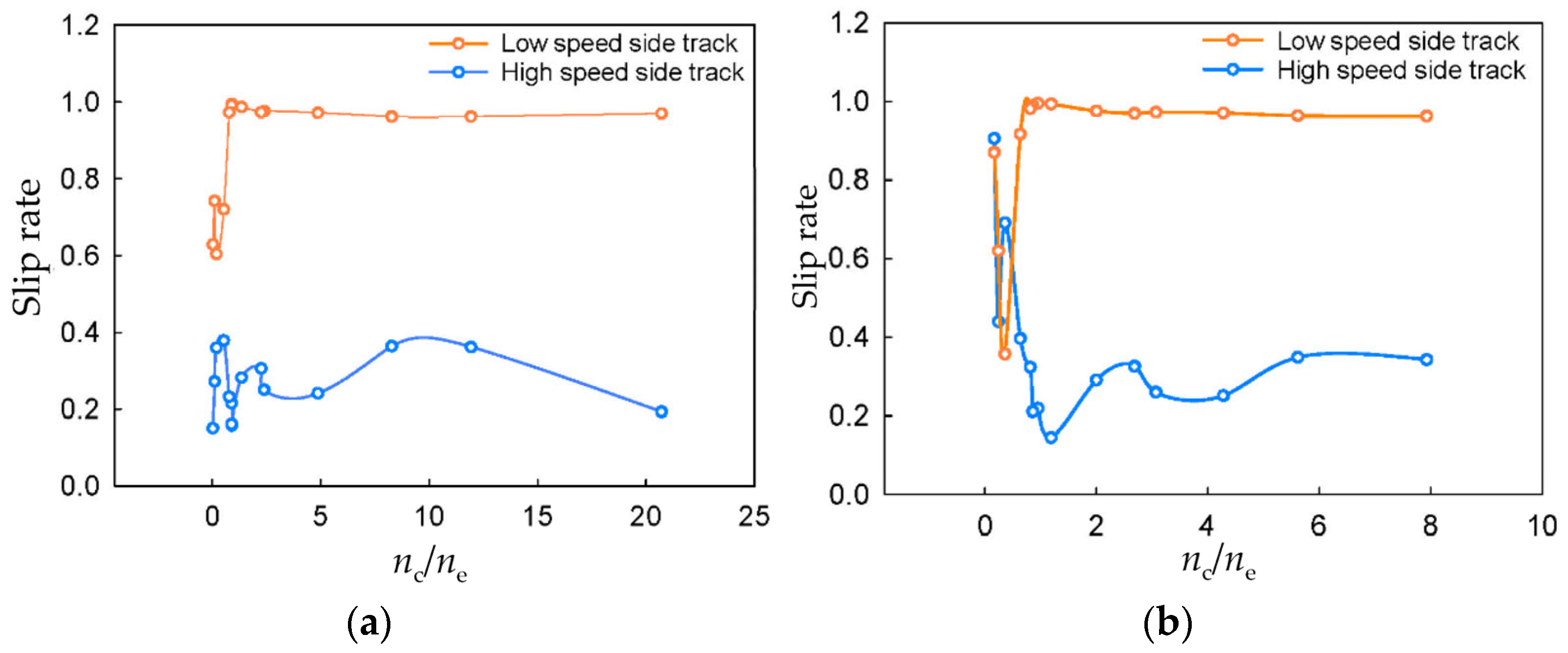
3.3.1. Relationship between Input Speed and Steering Parameters

The actual turning radius and the actual turning angular velocity of the crawler harvester on concrete pavement and in a field for various input speeds are shown in Figure 7 and Figure 8, respectively. As the transmission system of the harvester could realize differential direction reversal, differential steering, and unilateral braking steering, it could realize any turning radius. When the harvester was in the same gear and at the same speed, the larger the ratio between the running input speed and the steering input speed was, the larger the track steering radius and the smaller the average rotation angular velocity were. When the ratio was close to 1, the steering radius was close to half of the track gauge. On the concrete pavement, the slope of the linear fit of the theoretical turning radius was 0.707, whereas the slopes of the linear fits of the actual data were 0.913 during differential steering and 0.8 during differential direction reversal. On the field, the slope of the linear fit of the theoretical steering radius was 0.622, whereas the slopes of the linear fits of the actual data were 0.692 during differential steering and 2.129 during differential direction reversal.
When the crawler harvester steered on the concrete pavement and the field, the relationship between the low-speed side track slip rate σ1 and the high-speed side track slip rate σ2 with the ratio of the input speed and the fitted curve is shown in Figure 9. For the crawler harvester during differential steering (nc/ne > 1), with the decrease in the input speed ratio, the slip rate of the low-speed side track increased and approached 1. At this time, the walking input speed nc was close to the steering input speed ne, and the winding speed of the low-speed side decreased and approached 0. The displacement between the track and ground came from the implicated movement of the vehicle on the ground, and the track was in a state of sliding, while the slip rate of the high-speed side track was between 0.2 and 0.4. When the crawler harvester underwent differential direction reversal (nc/ne < 1), the low-speed side track began to reverse, the traction decreased, and the motion of the track changed to skidding.

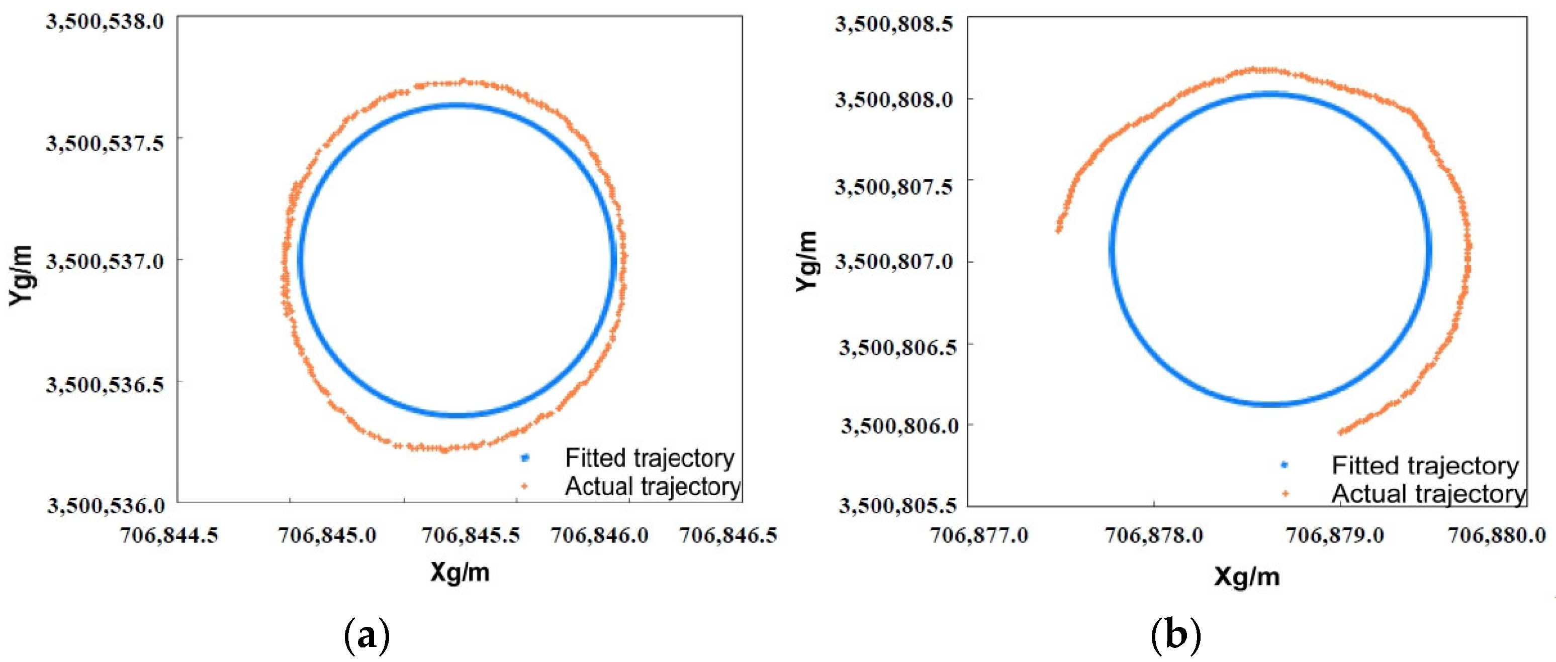
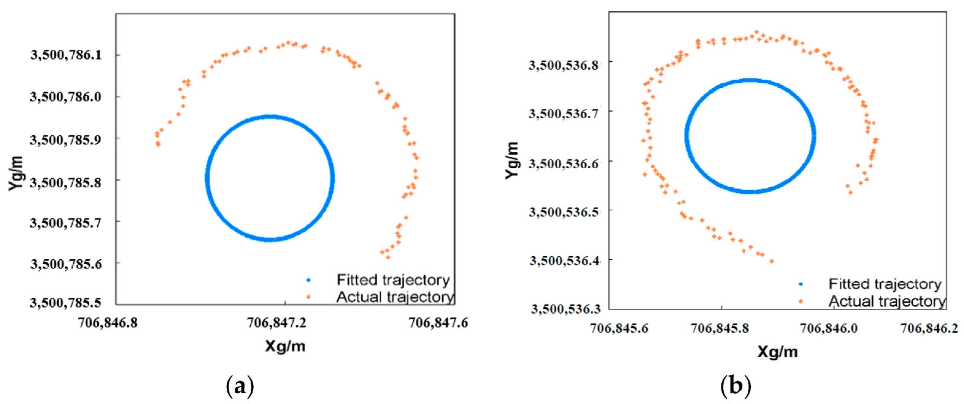
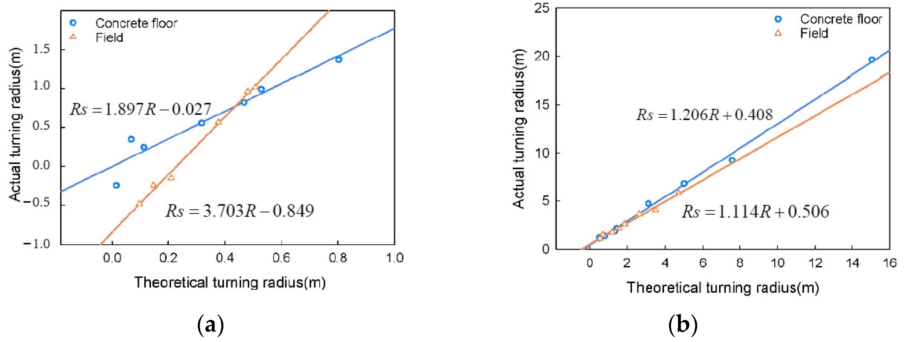
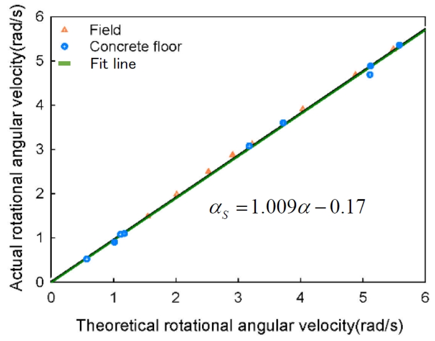
3.3.2. Correction Calculation of Steering Parameters

As can be seen from the previous analysis, the actual steering radius was larger than the theoretical steering radius due to the slip of the track, that is, the steering radius of the tracked vehicle increased. At the same time, the slip rate of the differential direction reversal and differential steering track were different for the concrete pavement and the field due to the different shear stresses, so the variation trends of the radius in the different steering modes were also different. Figure 10 and Figure 11 show the actual turning paths of the harvester and the fitted paths of the driving wheel of the harvester at different steering angles.
In an automatic driving scenario of a crawler harvester, the steering mode of the harvester determines the accuracy of operation and the control reliability. Reasonable analysis of the motion characteristics of different steering modes is the key to improving the working efficiency of the harvester. Due to the influence of track slippage, the actual steering motion parameters of the crawler harvester differed greatly from the theoretical values. Therefore, correction parameters of the steering radius and average steering angular velocity need to be calculated to correct the theoretical values. Figure 12 and Figure 13 show the fitted curves of the correction parameters of the steering radius and the average steering angular velocity.
A linear function was used to fit the correction parameters of the steering radius and average steering angular velocity. It can be seen from the Figure 12 that the correction parameters of the steering radius differed greatly for the different road surfaces and steering modes, so they were calculated separately under the different conditions. However, the average steering angular velocities had little difference, so the fitting calculation was carried out for all the data combined. On the concrete pavement, the fitted formula of the differential turning radius was Rs = 1.206R + 0.408, with R2 = 0.997. The fitted formula of the differential reversing turning radius was Rs = 1.807R − 0.027, with R2 = 0.871. On the field, the fitted formula of the differential turning radius was Rs = 1.114R + 0.506, with R2 = 0.986. The fitted formula of the differential reversing turning radius was Rs = 3.703R − 0.849, with R2 = 0.994. The fitted formula of average turning angular velocity was αs = 1.009α − 0.17, and the R2 value was 0.981.

4. Conclusions

In this paper, the transmission system structure of a driven steering crawler harvester chassis was analyzed, the speed relationship and steering characteristics under conditions of differential steering, differential direction reversal, and unilateral braking steering were analyzed. Based on a comparative study of the steering parameters obtained by RTK-GNSS measurements and the calculation results from a theoretical steering kinematics model of a crawler harvester, the mathematical expressions relating the walking power source and the steering power source to the winding speed, steering radius, and steering angle on both sides of the track were determined. Finally, the slip rate and the modified model of the track chassis slippage under different steering modes on concrete pavement and a field were obtained.
The experimental results showed that the larger the ratio of the running input speed to the steering input speed was, the larger the track steering radius and the smaller the average rotation angular velocity were under differential direction reversal and differential steering modes. There was a linear relationship between the actual steering parameters and the theoretical values. Compared with the actual results, the correlation coefficient of the tracked chassis steering parameters fitting model is close to 1. In the normal running state of the harvester, the theoretical steering parameters can be calculated and corrected in real time based on the input speed of the moving steering of the gearbox, which provides a reference for the study of the steering characteristics of tracked vehicles for different road surfaces and steering modes and the verification of the theoretical steering model.

Author Contributions

Conceptualization, Data curation, Methodology, Writing—Original Draft, Y.W.; Funding acquisition, Formal analysis, Writing—review and editing, Writing—review and editing, C.J.; Formal analysis, Investigation, T.Y.; Writing—review and editing, T.W.; Writing—review and editing, Y.N. All authors have read and agreed to the published version of the manuscript.

Funding

This work was supported by the National key research and development program [Grant No. 2021YFD2000503]; Special fund project for the construction of modern agricultural industrial technology system [Grant No. CARS-04-PS29].

Institutional Review Board Statement

Not applicable.

Informed Consent Statement

Not applicable.

Data Availability Statement

Data are contained within the article.

Conflicts of Interest

The authors declare no conflict of interest.

References

  1. He, Y.; Zhou, J.; Sun, J.; Jia, H.; Liang, Z.; Awuah, E. An adaptive control system for path tracking of crawler combine harvester based on paddy ground conditions identification. Comput. Electron. Agric. 2023, 210, 107948. [Google Scholar] [CrossRef]
  2. Hossain, M.; Hoque, M.; Wohab, M.; Miah, M.M.; Hassan, M. Technical and economic performance of combined harvester in farmers field. Bangladesh J. Agric. Res. 2015, 40, 291–304. [Google Scholar] [CrossRef]
  3. Lv, Y.; Wu, X.; Fu, Y.; Li, Z. Research on the Influence of Four-wheel Chassis ’Working Stroke Rate. J. Agric. Mech. Res. 2015, 37, 23–26+30. [Google Scholar] [CrossRef]
  4. Chen, T.; Xu, L.; Ahn, H.S.; Lu, E.; Liu, Y.; Xu, R. Evaluation of headland turning types of adjacent parallel paths for combine harvesters. Biosyst. Eng. 2023, 233, 93–113. [Google Scholar] [CrossRef]
  5. Guan, Z.; Zhang, M.; Jin, M.; Li, H.; Jiang, T.; Mu, S. Research progress of mechanical damage to soil bywalking mechanism of tracked agricultural equipment. J. Intell. Agric. Mech. 2022, 3, 62–70. [Google Scholar]
  6. Zhang, L.; Liu, G.; Qi, Y.; Yang, T.; Jin, C. Research progress on key technologies of agriculturalmachinery unmanned driving system. J. Intell. Agric. Mech. 2022, 3, 27–36. [Google Scholar]
  7. Munir, F.; Azam, S.; Yow, K.-C.; Lee, B.-G.; Jeon, M. Multimodal fusion for sensorimotor control in steering angle prediction. Eng. Appl. Artif. Intell. 2023, 126, 107087. [Google Scholar] [CrossRef]
  8. Yang, H.; Zhou, J.; Wang, X.; Wu, Y. Parameter Matching and Tillage Depth Control Method for Electric Crawler Tractor Platforms. J. Eng. Sci. Technol. Rev. 2021, 14, 83–90. [Google Scholar] [CrossRef]
  9. Inoue, E.; Mitsuoka, M.; Rabbani, M. Investigation of nonlinear vibration characteristics of agricultural rubber crawler vehicles. AMA-Agric. Mech. Asia Afr. Lat. Am. 2011, 42, 89. [Google Scholar]
  10. Shi, R.; Dai, F.; Zhao, W.; Liu, X.; Wang, T.; Zhao, Y. Optimal design and testing of a crawler-type flax combine harvester. Agriculture 2023, 13, 229. [Google Scholar] [CrossRef]
  11. Liu, Z.; Zhang, G.; Chu, G.; Niu, H.; Zhang, Y.; Yang, F. Design matching and dynamic performance test for an HST-based drive system of a hillside crawler tractor. Agriculture 2021, 11, 466. [Google Scholar] [CrossRef]
  12. Tang, Z.; Ren, H.; Li, X.; Liu, X.; Zhang, B. Structure Design and Bearing Capacity Analysis for Crawler Chassis of Rice Combine Harvester. Complexity 2020, 2020, 7610767. [Google Scholar] [CrossRef]
  13. Adams, B.; Darr, M.; Shah, A. Optimized Chassis Stability Relative to Dynamic Terrain Profiles in a Self-Propelled Sprayer Multibody Dynamics Model. J. ASABE 2023, 66, 127–139. [Google Scholar] [CrossRef]
  14. Sun, Y.; Xu, L.; Jing, B.; Chai, X.; Li, Y. Development of a four-point adjustable lifting crawler chassis and experiments in a combine harvester. Comput. Electron. Agric. 2020, 173, 105416. [Google Scholar] [CrossRef]
  15. Shinzato, Y.; Komesu, H.; Akati, T.; Ueno, M. Estimating the performance of small sugarcane harvesters in Okinawa. Eng. Agric. Environ. Food 2019, 12, 499–504. [Google Scholar] [CrossRef]
  16. Xu, L.; Zhou, Z.; Wang, B. Study on Matching Strategies of Hydro-Mechanical Continuously Variable Transmission System of Tractor. Int. J. Digit. Content Technol. Its Appl. 2013, 7, 843–849. [Google Scholar]
  17. Shao, X.; Yang, Z.; Mowafy, S.; Zheng, B.; Song, Z.; Luo, Z.; Guo, W. Load characteristics analysis of tractor drivetrain under field plowing operation considering tire-soil interaction. Soil Tillage Res. 2023, 227, 105620. [Google Scholar] [CrossRef]
  18. Liu, P.; Wang, Z.; Li, H.; Zhang, S.; Wei, W. Design and overcoming obstacles ability research of tracked driving chassis with planetary structure. Trans. Chin. Soc. Agric. Mach. 2014, 45, 17–23. [Google Scholar]
  19. Sun, S.; Wang, J.; Ke, J. New HST optimal design and test in harvester. J. Mach. Des. 2014, 31, 34–38. [Google Scholar] [CrossRef]
  20. Previati, G.; Gobbi, M.; Mastinu, G. Farm tractor models for research and development purposes. Veh. Syst. Dyn. 2007, 45, 37–60. [Google Scholar] [CrossRef]
  21. Letherwood, M.D.; Gunter, D.D. Ground vehicle modeling and simulation of military vehicles using high performance computing. Parallel Comput. 2001, 27, 109–140. [Google Scholar] [CrossRef]
  22. Du, P.; Ma, Z.; Chen, H.; Xu, D.; Wang, Y.; Jiang, Y.; Lian, X. Speed-adaptive motion control algorithm for differential steering vehicle. Proc. Inst. Mech. Eng. Part. D J. Automob. Eng. 2020, 235, 672–685. [Google Scholar] [CrossRef]
  23. Tang, S.; Yuan, S.; Hu, J.; Li, X.; Zhou, J.; Guo, J. Modeling of steady-state performance of skid-steering for high-speed tracked vehicles. J. Terramech. 2017, 73, 25–35. [Google Scholar] [CrossRef]
  24. Soodmand, I.; Heidari Shirazi, K.; Moradi, S. Analysis of ride comfort of a continuous tracked bogie system with variable configuration. Proc. Inst. Mech. Eng. Part. D J. Automob. Eng. 2020, 234, 3429–3439. [Google Scholar] [CrossRef]
  25. Xin, Z.; Jiang, Q.; Zhu, Z.; Shao, M. Design and optimization of a new terrain-adaptive hitch mechanism for hilly tractors. Int. J. Agric. Biol. Eng. 2023, 16, 134–144. [Google Scholar] [CrossRef]
  26. Matsuda, S.; Mukai, H. Effects of the Combination of Sloped Farm Field, Crawler Compaction and Open Channels on Moisture and Hardness and Temperature of the Surface Soil Layer after Disappearance of the Snow Cover. Trans. Jpn. Soc. Irrig. 2010, 77, 411–416. [Google Scholar]
  27. Fu, J.; Li, J.; Tang, X.; Wang, R.; Chen, Z. Optimization of Structure Parameters of the Grouser Shoes for Adhesion Reduction under Black Soil. Agriculture 2021, 11, 795. [Google Scholar] [CrossRef]
  28. Liu, Z.; Guo, J.; Ding, L.; Gao, H.; Guo, T.; Deng, Z. Online estimation of terrain parameters and resistance force based on equivalent sinkage for planetary rovers in longitudinal skid. Mech. Syst. Signal Process. 2019, 119, 39–54. [Google Scholar] [CrossRef]
  29. Yokoyama, A.; Nakashima, H.; Shimizu, H.; Miyasaka, J.; Ohdoi, K. Effect of open spaces between grousers on the gross traction of a track shoe for lightweight vehicles analyzed using 2D DEM. J. Terramech. 2020, 90, 31–40. [Google Scholar] [CrossRef]
  30. Nakashima, H.; Yoshida, T.; Wang, X.L.; Shimizu, H.; Miyasaka, J.; Ohdoi, K. On a Gross Traction Generated at Grouser for Tracked Agricultural Vehicles. IFAC Proc. Vol. 2013, 46, 311–316. [Google Scholar] [CrossRef]
Figure 1. Schematic diagram of chassis structure. 1. Transmission, 2. Double HST assembly, 3. Driving wheel, 4. Track, 5. Return roller, 6. Engine, 7. Frame, 8. Belt wheel, 9. Tension wheel.
Agriculture 14 00065 g001
Figure 2. Schematic diagram of the transmission system. (a) Schematic diagram of transmission mechanism; (b) Schematic diagram of planetary transmission. 1. Steering drive shaft 2, 2. Steering drive shaft 1, 3. Reversing shaft, 4. Reduction shaft, 5. Belt pulley, 6. Input shaft, 7. Walking drive shaft 2, 8. Walking drive shaft 1, 9. Walking drive shaft 3, 10. Steering drive shaft 3, 11. Steering drive shaft 4, 12. Planet gear, 13. Travel drive shaft 4, 14. Pinion, 15. Internal gear, 16. Planet rack, 17. Sun gear, 18. Center gear, 19. Half shaft. In the figure, n represents the speed of the shaft, r/s; ω is the angular velocity of this axis, rad/s.
Agriculture 14 00065 g002
Figure 3. Schematic diagram of linear and steering motions of track chassis. (a) Straight-line driving; (b) Differential direction reversal; (c) Unilateral braking steering; (d) Differential steering.
Agriculture 14 00065 g003
Figure 4. Relationship between steering radius and input speed.
Agriculture 14 00065 g004
Figure 5. Schematic diagram of tracked vehicle steering movement. (a) Unilateral braking steering (b) Differential steering (c) Differential direction reversal.
Agriculture 14 00065 g005
Figure 6. Steering diagram of crawler harvester. Note: UTM denotes a universal transverse Mercator grid system, where UTM-E is the projected distance from the central meridian of the longitude region and UTM-N is the projected distance from the equator. Point P is the installation position of the global navigation satellite system (GNSS). Point Os is the center of the turning moment. d is the distance between point P and the central axis. u is the distance between the antenna and the caterpillar axis. Rs is the turning radius at the central axis.
Agriculture 14 00065 g006
Figure 7. Variations of steering radius with input speed. (a) Concrete pavement (b) Field.
Agriculture 14 00065 g007
Figure 8. Average rotation angular velocity variations with input speed. (a) Concrete pavement (b) Field.
Agriculture 14 00065 g008
Figure 9. Sliding rate variations with input speed. (a) Concrete pavement (b) Field.
Agriculture 14 00065 g009
Figure 10. Differential steering path trajectory. (a) Concrete pavement (b) Field.
Agriculture 14 00065 g010
Figure 11. Trajectory of differential reversal path. (a) Concrete pavement (b) Field.
Agriculture 14 00065 g011
Figure 12. Correction parameters of steering radius. (a) Error reversal radius correction parameter (b) Differential steering radius correction parameter.
Agriculture 14 00065 g012
Figure 13. Average steering angular velocity correction parameters.
Agriculture 14 00065 g013
Table 1. Crawler harvester and antenna position parameters.
ParameterNumerical Value
Machine size (length × width × height)/(mm)5640 × 2600 × 2800
Weight/(kg)4030
Track grounding length/center distance/(mm)2300
Track gauge/(mm)1200
Mean ground voltage (kPa)19.1
Track pitch × number × width90 mm × 58 segment × 550 mm
Number of driving gear teeth8
Spacing between antenna and central axis/(mm)740
Spacing between antenna and track axis/(mm)420
Table 2. Test results of steering motion parameters and corrected parameters of crawler harvester on concrete pavement.
No. n ¯ c n ¯ e v ¯ R v ¯ L n ¯ c / n ¯ e R ¯ R ¯ S ω ¯ ω ¯ s σ ¯ 1 σ ¯ 2 Steering Type
1157.0657.5842.0871.89220.7115.03619.6430.570.5230.1930.97a
2161.9213.5742.2231.87511.9297.5599.2621.0160.9040.3620.962a
3122.06514.761.7381.3598.275.0165.8361.1121.0790.3640.962a
480.63216.5571.2340.8094.873.0914.7411.1761.1020.2410.972a
5101.37742.3521.830.7432.3941.4292.2013.1783.0790.250.976a
6111.03349.1262.0450.7722.261.3281.8753.7233.6020.3060.973a
792.25868.1872.0460.2961.3530.8031.3685.1164.690.2820.987a
861.93968.2931.662−0.090.9070.5381.25.1244.8860.1580.995a
966.74974.4711.802−0.1090.8960.5321.175.5885.3590.1620.994a
1061.87269.3091.674−0.1040.8930.5290.995.365.190.2150.992a
1140.45251.4221.171−0.1460.7870.4680.8183.853.9830.2320.973b
1245.89385.7621.676−0.5160.5350.3180.5546.4086.20.3790.721b
1317.75492.9781.418−0.9680.1910.1130.2446.986.7570.360.604b
147.28363.550.908−0.7210.1150.0680.3434.7584.4020.2720.743b
152.839108.7391.424−1.3520.0260.015−0.2488.1198.9550.1510.629b
Table 3. Test results of steering motion parameters and correction parameters of field crawler harvester.
No. n ¯ c n ¯ e v ¯ R v ¯ L n ¯ c / n ¯ e R ¯ R ¯ S ω ¯ ω ¯ s σ ¯ 1 σ ¯ 2 Steering Type
1163.6820.6452.3431.8127.9284.7045.9041.5491.4860.3430.963a
2150.54426.8192.2541.5665.6133.4874.0522.0121.9820.3490.964a
3143.93433.6542.2581.3954.2792.6343.6512.5252.4990.2510.971a
4118.98238.7982.0081.0123.0671.8832.6442.9112.8780.260.973a
5115.34942.9822.0150.9122.6841.592.1393.2253.1170.3260.97a
6107.41653.8162.0530.6721.9961.1921.744.0383.9110.2910.976a
777.2465.1021.8150.1481.1860.7041.484.8844.6850.1450.994a
869.45773.1861.82−0.0580.9490.5641.0975.4915.2650.2190.996a
963.41174.0891.755−0.1460.8560.5081.0115.5595.3980.2110.99b
1060.57274.6681.727−0.1890.8110.4810.9615.6034.7010.3240.982b
1134.40854.3481.134−0.2610.6330.3770.5634.0783.6920.3970.917b
1228.56180.5911.396−0.6720.3540.21−0.1596.0476.1550.6910.357b
1311.89749.9180.791−0.490.2380.147−0.2453.7453.2930.440.62b
1414.2786.731.294−0.9310.1650.097−0.4866.5086.6840.9060.87b
Note: n ¯ c is the average speed of the central gear (r/s), n ¯ e is the average speed of the planetary gear (r/s), v ¯ R is the average left-winding speed (m/s), v ¯ L is the right winding average speed (m/s), R ¯ is the average theoretical turning radius (m), R ¯ s is the average actual turning radius (m), ω ¯ is the theoretical average rotational angular velocity (rad/s), ω ¯ s is the actual average rotational angular velocity (rad/s), σ ¯ 1 is the average slip rate of the high-speed side track, and σ ¯ 2 is the average slip rate of the side track at low speeds, a is the differential steering, b is the differential direction reversal.
Disclaimer/Publisher’s Note: The statements, opinions and data contained in all publications are solely those of the individual author(s) and contributor(s) and not of MDPI and/or the editor(s). MDPI and/or the editor(s) disclaim responsibility for any injury to people or property resulting from any ideas, methods, instructions or products referred to in the content.

