Article

Design and Test of a Low-Loss Soybean Header Based on Synchronous Profiling

College of Mechanical and Electrical Engineering, Sichuan Agricultural University, Ya’an 625014, China
*
Author to whom correspondence should be addressed.
Agriculture 2023, 13(8), 1580; https://doi.org/10.3390/agriculture13081580
Submission received: 20 June 2023 / Revised: 19 July 2023 / Accepted: 31 July 2023 / Published: 8 August 2023
(This article belongs to the Special Issue Agricultural Machinery Design and Agricultural Engineering)

Abstract

:
A synchronous-profiling, low-position-cutting, flexible-reel-belt-conveyor, low-loss soybean header was designed to address the problems of a lack of soybean harvesting machines supporting soybean-corn strip intercropping, the few existing soybean headers, and the high loss rate of soybean headers. By establishing a dynamic model of the synchronous-profiling cutting device, the key structure and operation parameters that affect the performance of synchronous profiling were determined, while the key parameters of the flexible-reel-belt conveyor device were determined by theoretical analysis. Based on ADAMS rigid-flexible coupling, simulation analysis was conducted on the working process of the synchronous-profiling cutting device, verifying that the profiling cutting device can effectively control the height of the cutter off the ground with undulating ground and that the cutting device can accurately and quickly respond to ground excitation, meeting the requirements of synchronous-profiling, low-position cutting. Field tests showed that the loss rate and stubble height of the soybean headers are 1.34% and 70.36 mm, respectively, which are 55% and 22.7% lower than the existing reel-type rigid soybean headers, meeting the actual production requirements. This study can provide a reference for the structural design of soybean harvesting headers and the reduction of header losses.

1. Introduction

Soybean-corn strip intercropping is the main planting technology in China, which effectively solves the conflict between soybean and corn for land [1,2,3]. Realizing mechanized harvesting is of great significance for popularizing this technology. At present, there are few soybean harvesting machines supporting the strip intercropping model at home and abroad. The header is a key component of a harvester, and the soybean harvester adopts a rigid header of the reel type. According to data, the total loss rate in the soybean harvesting process can be as high as 10%, and the header loss accounts for over 80% of the total loss in the harvesting process [4,5]. According to the estimated total soybean production in China in 2022 of approximately 20.28 million tons, reducing the loss by 1% can save 200,000 tons of grain [6]. Reducing harvest losses helps increase grain supply and is of great significance for ensuring national food security [7,8].
The installation height of the cutter in the existing reel-type rigid soybean headers is higher from the ground. If the height of the soybean plant’s bottom pod is low, the cutter is prone to missing the soybean, resulting in missed harvest losses. If the height of the cutter is lowered, it is more likely to shovel soil and cause “muddy face” loss [9,10]. At the same time, soybean plants are hit multiple times by the reel, resulting in the loss of fried soybean pods and leading to a sharp increase in header losses. Domestic and foreign scholars have conducted relevant research on the structure of headers to address the issue of high losses. Kassen et al. [11,12,13] designed an adaptive header height system based on the RFL method, the IROD algorithm, and a soil-machine system, which improved the accuracy of header profiling but required high system control accuracy. Li [14] developed a soybean profiling header by means of a four-link profiling mechanism to achieve low-level cutting of soybeans. Jin et al. [15] designed main-subplate compression-type header profiling, which effectively improved the profiling sensitivity and ground perception ability of the header. Xie [16] developed a soybean belt conveyor header by designing an intermediate conveying device between the cutter and the churn, but there was still a problem because the reel struck the soybean plants many times. In summary, despite domestic and foreign emphasis on header control strategy and structural design, the study of synchronous-profiling low-cutting technology is rarely reported. At the same time, because of the biological characteristics of easy-to-fry soybean pods, there is still a problem of high reel loss in the operation of the existing reel-type rigid soybean header.
To address the above problems, this paper designed a low-loss soybean header based on synchronous profiling and determined the structural parameters of the key components through theoretical analysis. ADAMS2018 software was used to analyze the motion process of the synchronous profiling device and verify the low-cutting performance of the synchronous profiling. Comparative field tests based on the agronomic characteristics of the soybean-corn strip intercropping model were conducted.

2. The Overall Structure and Working Principle of the Header

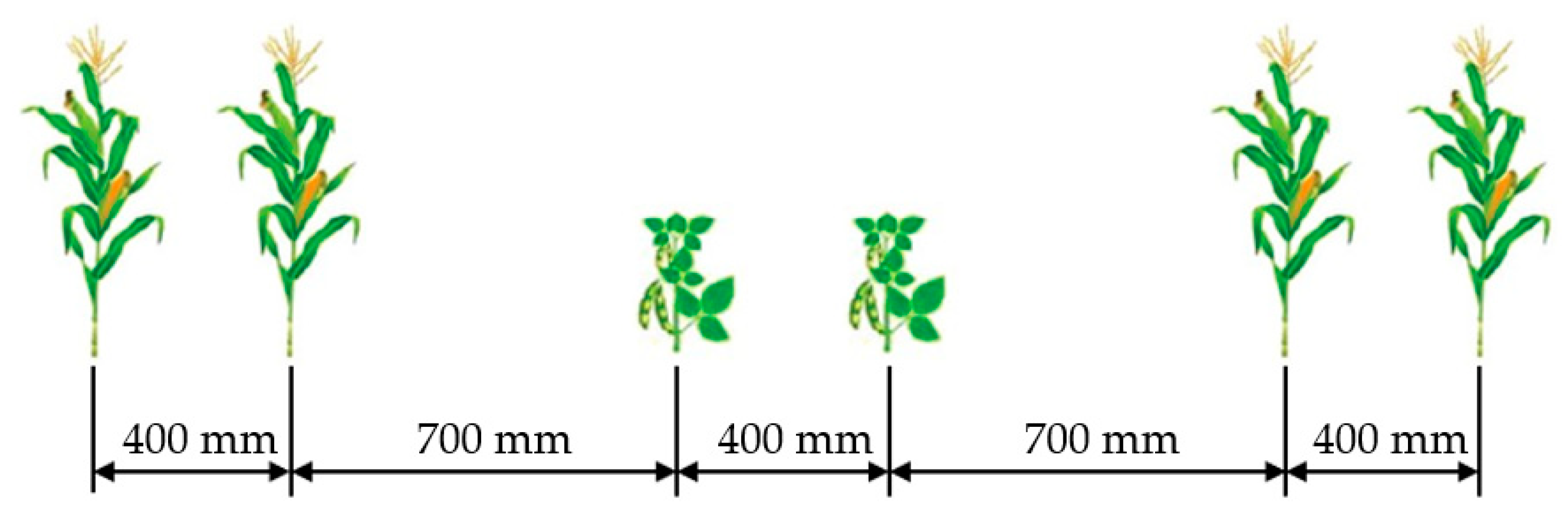
2.1. Requirements for Matching Machines for Soybean-Corn Strip Intercropping

Figure 1 shows the agronomic model of narrow-row and high-density planting based on the strip intercropping of two rows of corn and two rows of soybeans that is used in the southwestern hills and mountain areas. In order to facilitate the narrow-row operation of the machine and avoid the machine hitting the corn on both sides, the total width of the supporting soybean harvesting equipment is required to be less than 1600 mm [17]. Therefore, the total width of the low-loss soybean header was designed to be 1350 mm, which can complete the soybean belt-harvesting operation with a row spacing of 200–400 mm and meet the requirements of matching machines for soybean-corn strip intercropping.

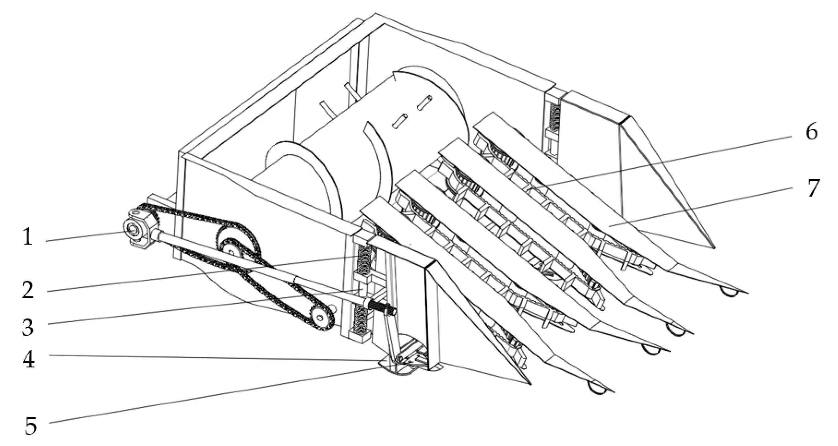
2.2. Overall Structure of the Header

The low-loss soybean header was primarily comprised of a synchronous-profiling cutting device and a flexible reel conveyor device, as shown in Figure 2. The synchronous-profiling cutting device consisted of a profiling plate, profiling spring, reciprocating low-position single-action cutter, guiding column, etc. The flexible reel conveyor device comprised a flexible reel conveyor belt, main and driven wheels, a grain divider, and other components. The main technical parameters are shown in Table 1.
During operation, the grain divider guides the soybean plant and directs it into the corresponding channel of the flexible reel conveyor belt. The reel belt rotates at a constant speed to flexibly reel the upper end of the soybean plant, ensuring orderly clamping as it is delivered to the synchronous-profiling cutting device. Under the influence of gravity and spring force, the profiling plate closely follows the ground, and both the profiling plate and cutter move synchronously up and down along the guide column, creating undulations on the surface. The reciprocating cutter synchronously and precisely cuts the lower end of the plant, while the cut plant moves to the end of the reel belt, where it is thrown to the churning at a certain initial speed.

3. Key Component Design

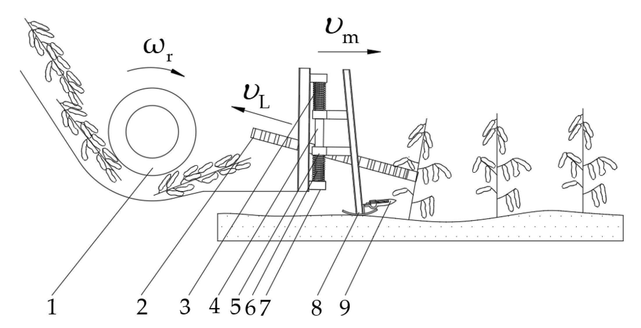
3.1. Synchronous-Profiling Cutting Device

In the soybean-corn strip intercropping, due to the low podding position of soybean varieties, in order to reduce header harvest losses, it was necessary to ensure that the stubble height of soybean plants was 5–10 cm during harvest. While the existing rigid soybean header cutter was high above the ground, the low-cutting performance of the cutter was poor during harvesting. The cutter was prone to missing cutting and shoveling, resulting in soybean leakage loss and mud blossoms [16,18]. Therefore, a synchronous-profiling cutting device was designed for the above problems, as shown in Figure 3.

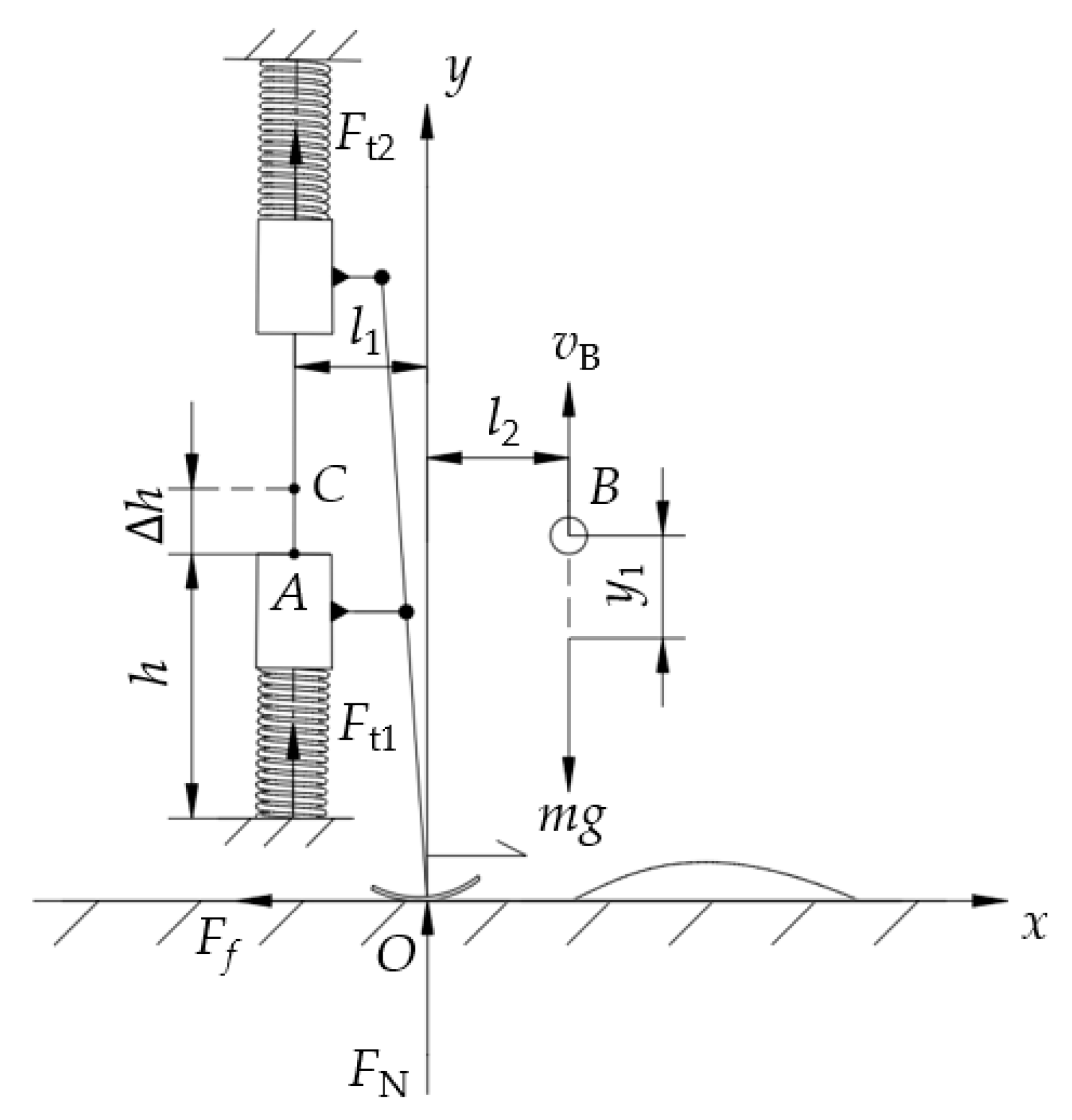
3.1.1. Dynamic Modeling of a Synchronous-Profiling Cutting Device

To study the kinematic characteristics of the synchronous-profiling cutting device during the profiling motion phase, the kinetic equations of a single degree of freedom were established by the second Lagrange equation [19]. During the operation, the profiling plate and the cutting device made a translational movement along the y-direction, and the dynamic model of the synchronous-profiling device was established, as shown in Figure 4.
The Lagrange equation of the system can be represented by kinetic energy and potential energy, namely:
d d t T y ˙ T y + V y = Q
where Q is the generalized force of the system, J; T is the kinetic energy of the system, J; and V is the potential energy of the system, J.
The expression for system kinetic energy was as follows:
T = 1 2 m y ˙ 1 2
The system’s potential energy expression was as follows:
V = 1 2 k c y 1 2 + m g y 1
where kc is the equivalent spring stiffness, N/mm. Bring Equations (2) and (3) into Equation (1) to obtain the system differential equation of motion:
m 1 y ¨ 1 m 1 y ˙ 1 + k c y 1 + m 1 g = 0
Through the analysis of Equation (4), it can be concluded that the generalized coordinates y, spring stiffness kc, mass, center of mass position, and other parameters of the synchronous profiling device had an impact on the dynamic response of the system when the synchronous profiling device was profiled close to the ground. When the size of the synchronous profiling device and the installation points of the spring were determined, its mass, center of mass position, and working stroke were also determined. At this time, the dynamic response of the system only depended on the spring stiffness.

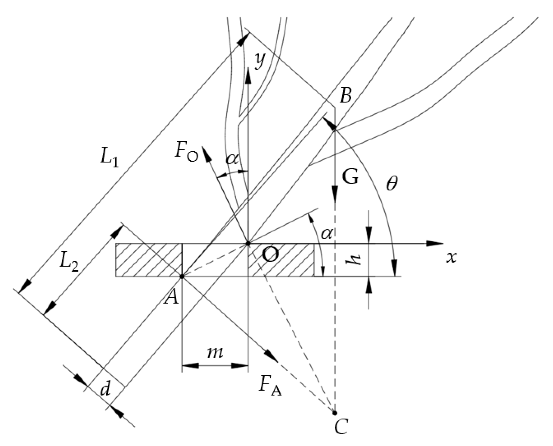
3.1.2. Force Analysis of a Synchronous Profiling Cutting Device

To determine the value of the spring stiffness kc, the force analysis of the profiling device was performed, as shown in Figure 4. The equilibrium equation was listed as:
F x = 0 M O = 0 k c Δ y G + F N = 0 ( F t 1 + F t 2 ) × l 1 G l 2 = 0 F f = μ F N G = m g
where Δ y is the spring displacement, mm; μ is the coefficient of dynamic friction between the ground and the profiling plate, generally 0.3–0.7.
In order to make the profiling plate close to the ground, the ground needed to maintain a certain force on the profiling plate, that is, FN > 0.
The profiling displacement was designed to be 70 mm, l1 was 20 mm, l2 was 35 mm, and the overall mass was 23.7 kg. According to Equation (5), the profiling spring stiffness kc was > 5.81 N/mm. Considering that the spring stiffness was too large to make the profiling device sink seriously, the design took 6 N/mm to ensure the profiling accuracy during operation.

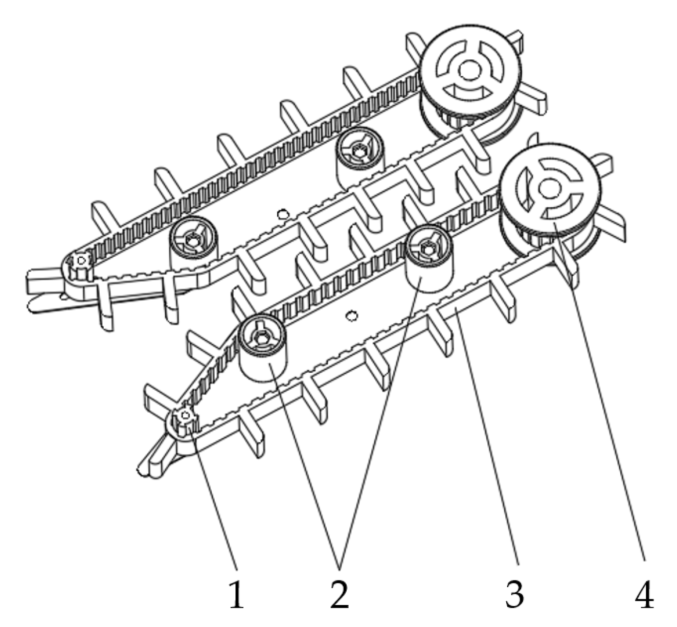
3.2. Design of a Flexible Reel-Belt Conveyor

In view of the problems of high reel loss and easy congestion when the existing soybean header harvested strip intercropping soybeans, this paper designed a flexible-reel-belt conveyor device, whose structure is shown in Figure 5. The flexible reel belt was made of rubber with good flexibility and small stiffness to reduce the impact force of reel collisions on the plant and reduce reel loss.
To determine the key parameters of the flexible-reel-belt conveyor device, a mechanical analysis model as shown in Figure 6 was established with the plant forward tilt as an example [20,21].
The balance equation for the plant clamping and conveying process was as follows:
F A × sin θ F O × sin α = 0 F O × cos α F 2 × cos θ G = 0 G × cos θ L 1 L 2 F O × m 2 + h 2 = 0
The geometric relationship can be obtained from Figure 6:
tan α = h / m
tan θ = h m d cos 90 ° θ = h m d sin θ
According to the trigonometric relationship, the union (6)~(8) can be simplified to obtain:
L 1 L 2 = m 2 + h 2 cos θ m h tan θ = m 2 + h 2 tan θ d
In order to ensure the conveying efficiency of the flexible reel belt, the height h of the reel belt teeth should meet the following conditions:
v L B v m k h
where k is the plant accumulation coefficient, generally ranging from 18 to 33 [22].
According to the agronomic characteristics of strip intercropping soybean with a dense plant spacing of 8–10 cm [23], the plant accumulation coefficient should be taken as the larger value, and in this design, k = 25. The forward speed of the harvester vm was 1.1 m/s, and the speed vL of the reel belt was 0.5–2 m/s [24], taking 1.8 m/s. The width B of the header was 1300 mm, and the height of the teeth of the belt calculated from Equation (10) was h ≥ 31.7 mm, taking h = 32 mm.
To ensure smooth transportation, the spacing between the teeth of the reel belt m should not exceed the diameter of the soybean canopy dc. To minimize seed loss caused by multiple impacts of the reel belt on the plants, the number of reel spring teeth should not exceed three within the canopy diameter range. Therefore, the spacing between the teeth of the reel belt should satisfy the following condition [25]:
m < d c min 2 × m > d c max
where m is the spacing between the teeth of the reel belt, mm; dcmin is the minimum canopy diameter of soybean, mm; and dcmax is the maximum canopy diameter of soybean, mm.
Based on field measurements, the average minimum and maximum canopy diameters of strip-intercropped soybeans were found to be 84 mm and 132 mm, respectively. Combined with the average distance from the center of gravity of the soybean plant to the cutting point of 450 mm and the distance from the bottom of the reel belt to the cutting point L2 of 100 mm, the tooth spacing of the reel belt m can be determined using Formulas (7), (9) and (11). After considering the overall layout of the reel belt, the design of the reel belt tooth spacing was set at 68 mm.

4. Simulation Analysis of a Synchronous-Profiling Device Based on ADAMS Rigid-Flexible Coupling

ADAMS software is widely used in various fields of mechanical system dynamics simulation analysis and can reliably and effectively calculate and analyze the kinematics and dynamics performance of a virtual mechanical system model [26,27]. In this study, ADAMS software was used to simulate and analyze the motion process of a synchronous-profiling cutting device on a sine wave ground.

4.1. Simulation Model Establishment and Parameter Settings

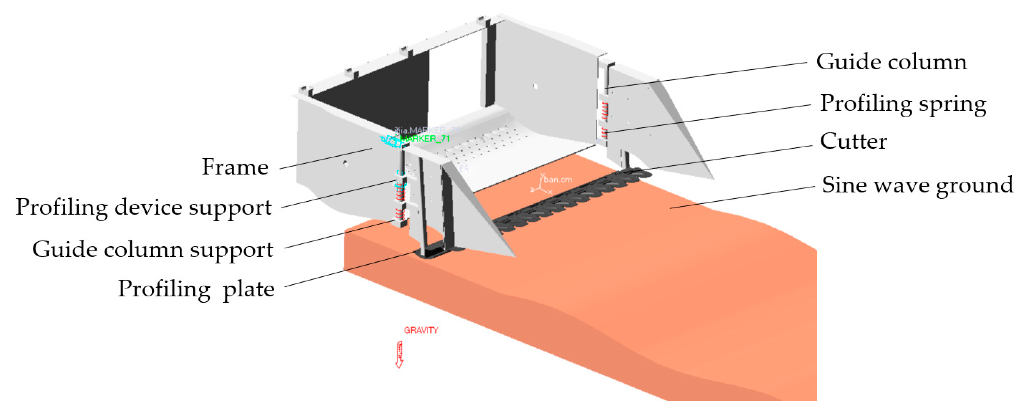
4.1.1. Simulation Model

In order to simulate the undulating terrain of clay soil in hilly and mountainous areas, a sine wave ground model was established, with the maximum undulating height of the ground set at 70 mm. In order to further study the operation of the profiling device on undulating ground, a three-dimensional assembly model of the profiling device and sine wave ground was established by Solid Works. Save in X_T file format and import into ADAMS. The virtual prototype model mainly includes the frame, profiling device support, profiling plate, guide column, guide column support, cutter, and sine wave ground, as shown in Figure 7.

4.1.2. Parameter Setting of a Simulation Model

According to the motion characteristics of each part, add a fixed constraint between the sine wave ground and the earth. Add a moving pair between the frame and the earth. A moving pair was added between the guide column support and the profiling device support, and a contact constraint was added between the profiling plate and the sine wave ground. The ground material was defined as viscous soil with a density of 7.801 × 10⁻⁶ kg/mm3, a Poisson’s ratio of 0.29, and an elastic modulus of 2.07 × 10⁵ N/mm2 [28]. The profiling plate was made of 65 Mn spring steel, with a density of 7.801 × 10⁻⁶ kg/mm3, a Poisson’s ratio of 0.3, and an elastic modulus of 1.965 × 10⁵ N/mm2 [29,30]. Other parts were made of ordinary carbon steel. A tension spring was introduced between the guide column support and the profiling device support, with a spring stiffness of 6 N/mm, to replace the force exerted by the spring on the profiling plate. The View Flex module in ADAMS software was used to designate the profiling plate and ground as flexible bodies, while the other parts were considered rigid bodies.
Referring to the commonly used operating speeds of soybean combine harvesters, the machine’s forward speed was set to three levels: 0.9 m/s, 1.2 m/s, and 1.4 m/s. The drive function was added, and the simulation time was set to 3.5 s with a step length of 200 steps.

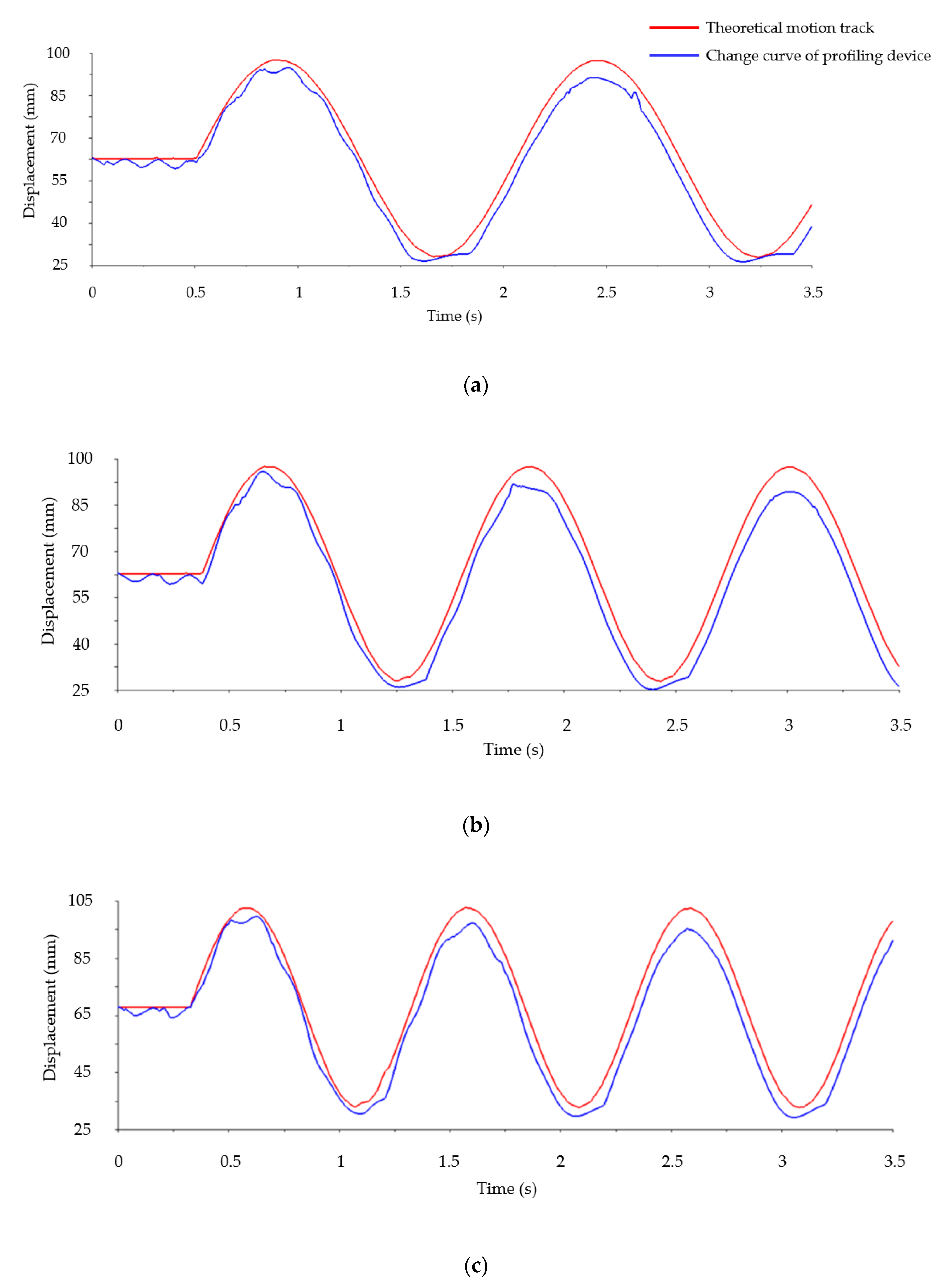
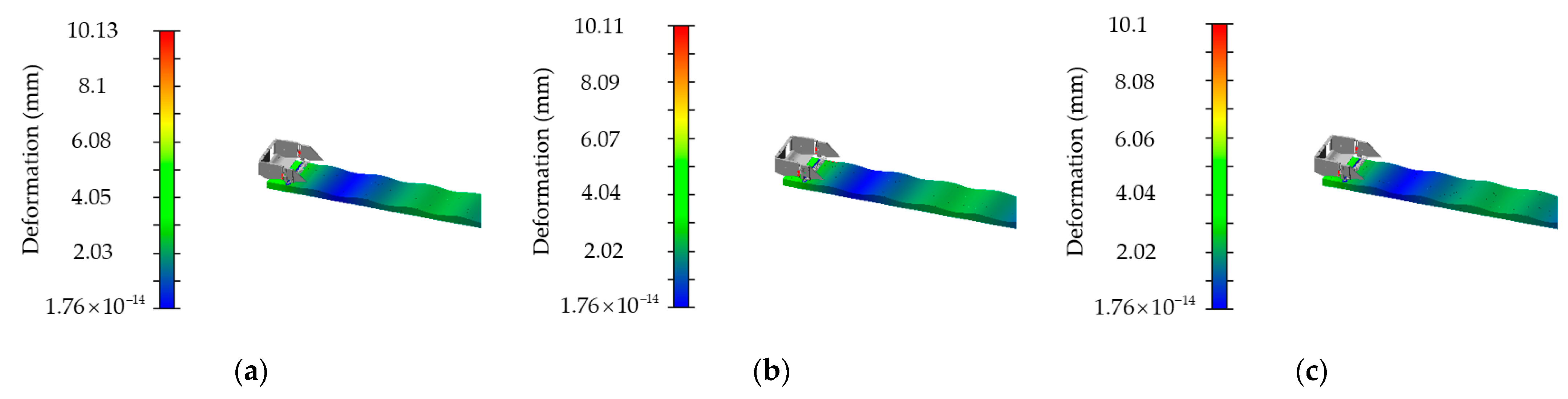
4.2. Analysis of Simulation Results
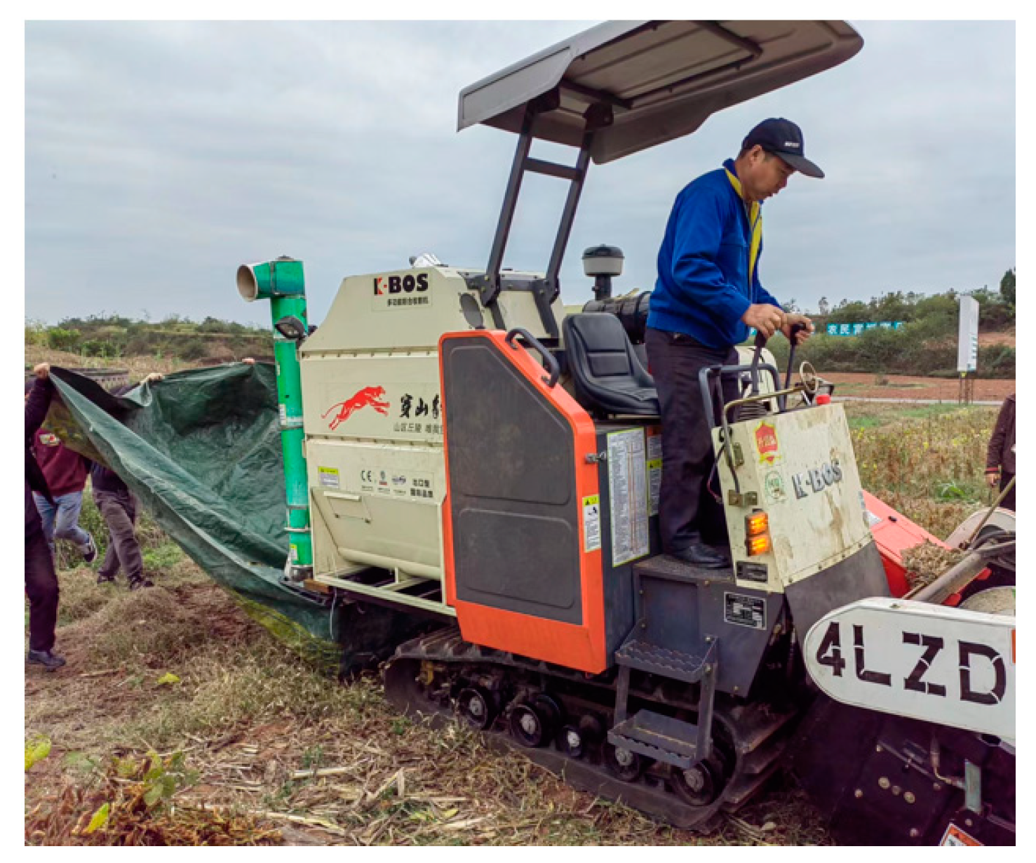
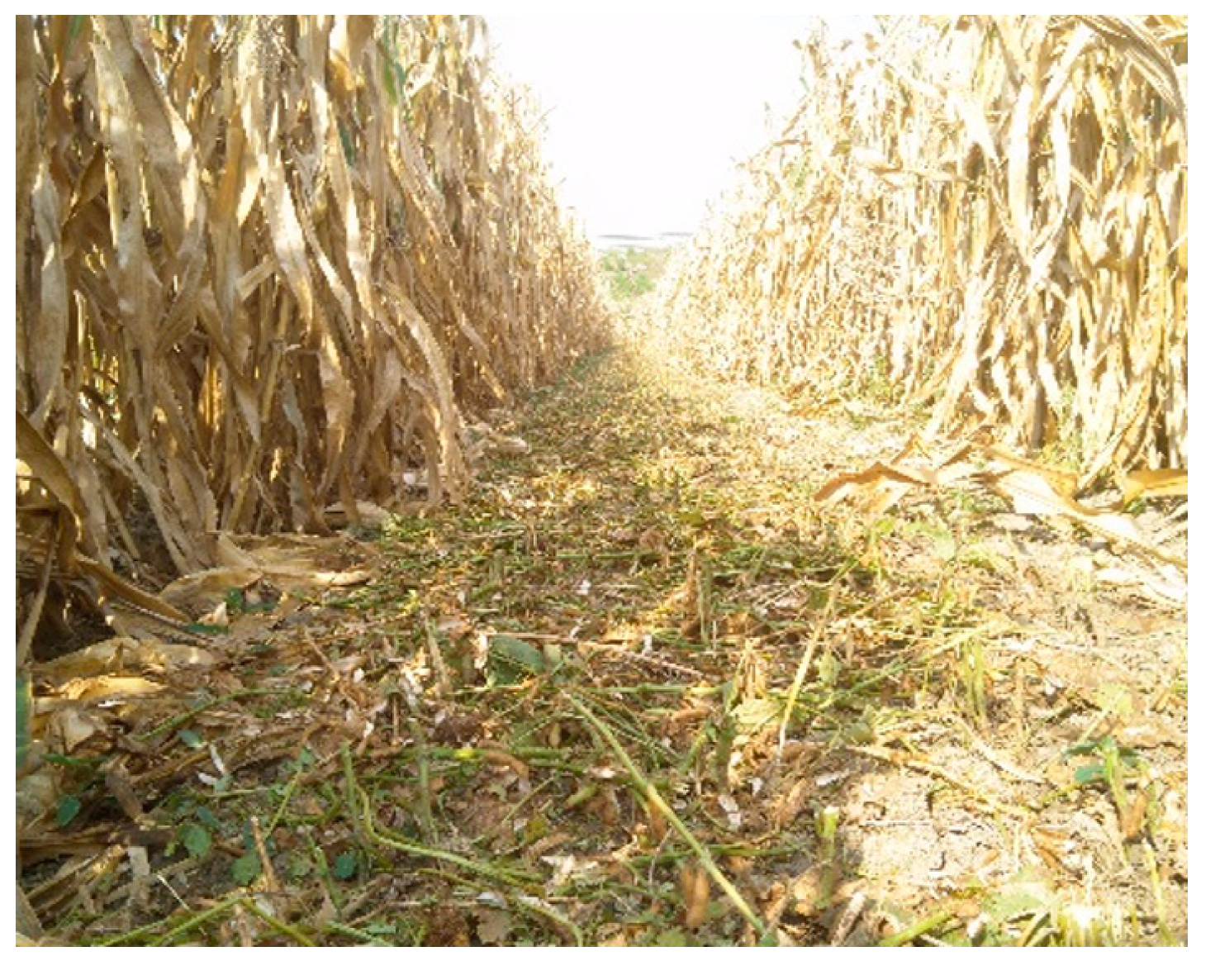
The resulting motion curve of the profiling device on the sine wave ground was obtained through post-processing, as shown in Figure 8.
Figure 8 shows the variation curve of the profiling device, and the sine wave ground variation curve tends to be consistent at different machines’ forward speeds. Due to a certain impact between the profiling plate and the ground, there was shaking when the profiling plate was attached to the ground for profiling. The shaking situation showed a slight positive correlation change as the machine’s forward speed gradually increased. However, under the action of the self-weight and spring force of the profiling device, the shaking error range was within plus or minus 5 mm. The trajectory change of the profiling device was consistent with the sine wave ground, indicating that the profiling effect of the profiling plate was better when it was attached to the ground. Therefore, compared with the existing soybean rigid header cutter, the profiling cutting device can better control the height of the cutter from the ground on undulating ground.
From the changing curves in the figure, it can be observed that there was a time difference between the profiling device and the theoretical motion track. The phase difference can be determined by comparing the peak time differences between the profiling device and the theoretical motion track. For machine forward speeds of 0.9 m/s, 1.2 m/s, and 1.4 m/s, the phase differences were calculated as 0.0395 s, 0.0446 s, and 0.053 s, respectively. These results indicated that the phase difference of the profiling device increased slightly with the machine’s forward speed, but the profiling error was small. The cutting device adopted synchronous profiling, which meant that the profiling plate was directly arranged at the bottom of the cutting device and that the distance between the profiling plate and the cutting device was closer. Through the simulation analysis, it can be concluded that the profiling cutting device can respond to the ground excitation accurately and quickly and meet the requirements of synchronous profiling and low-cutting.
Figure 9 shows that the sag of the profiling device can be determined through post-processing. With the forward speeds of the machine set at 0.9 m/s, 1.2 m/s, and 1.4 m/s, the maximum sinkage of the profiling device measures 10.13 mm, 10.11 mm, and 10.1 mm, respectively. The average sinkage was calculated to be 10.11 mm. This indicated that the profiling plate can perceive real-time ground changes when operating on the ground.

5. Field Test

5.1. Test Conditions

In order to determine the field operation performance of soybean headers, a field test was conducted in the Modern Grain and Oil Park of Renshou County, Sichuan Province, in November 2022. The experimental soybean variety used was Nandou 25, with an average row spacing of soybean plants between 115 and 300 mm. The average plant height was 570 mm, the average bottom pod height was 130 mm, and the average grain water content was 14.7%. The soil at the test site was purple soil with flat and undulating terrain, 18.1% water content, and a firmness of 5270 kPa. According to the working principle of the soybean header structure, the designed synchronous-profiling cutting device and flexible-reel-belt conveyor device were configured on the soybean combined harvesting header for field testing. Figure 10 shows the prototype field test. The effect of soybean cutting is shown in Figure 11.

5.2. Test Method

According to the relevant provisions of “Soybean Combined Harvester Machinery” (NY/T738-2020) and GB/T8097-2008 “Combine Harvester Test Method”, the performance test of the header was carried out. The loss rate of the header and the average stubble height were used as evaluation indexes.
Before the test, the preset height of the synchronous-profiling cutting device from the ground was 70 mm, and three test areas with a length of 20 m and a width of 1.3 m were randomly selected. Secondly, in order to prevent the impact of debris discharged from the machine on the loss rate of the header, a waterproof cloth was used to catch all impurities, such as straw discharged from the tail of the machine. During the test, the whole machine stably walked for 20 m. All the fallen seeds, pod seeds, and missed soybean seeds were collected and weighed together on the test plot after cutting. The grain loss rate of the header in the test area was calculated. The test was repeated three times under the above conditions. At the same time, a comparative test was conducted on the existing reel-type rigid soybean header. After the test, a test area was randomly selected, and the stubble height was manually measured every 0.3 m with a steel ruler. Fifty sampling points were measured.
The calculation formula for each evaluation index was as follows:
Y L = W L W z × 100 %
h ¯ = i = 1 n h i n
where YL is the header seed loss rate, %; WL is the mass of fallen seeds collected in the test area, g. WZ is the total mass of soybean seeds in the test area, g; h ¯ is the average stubble height of soybean, mm; hi is the stubble height measured in the i test area; and n is the number of measurements in the test area.

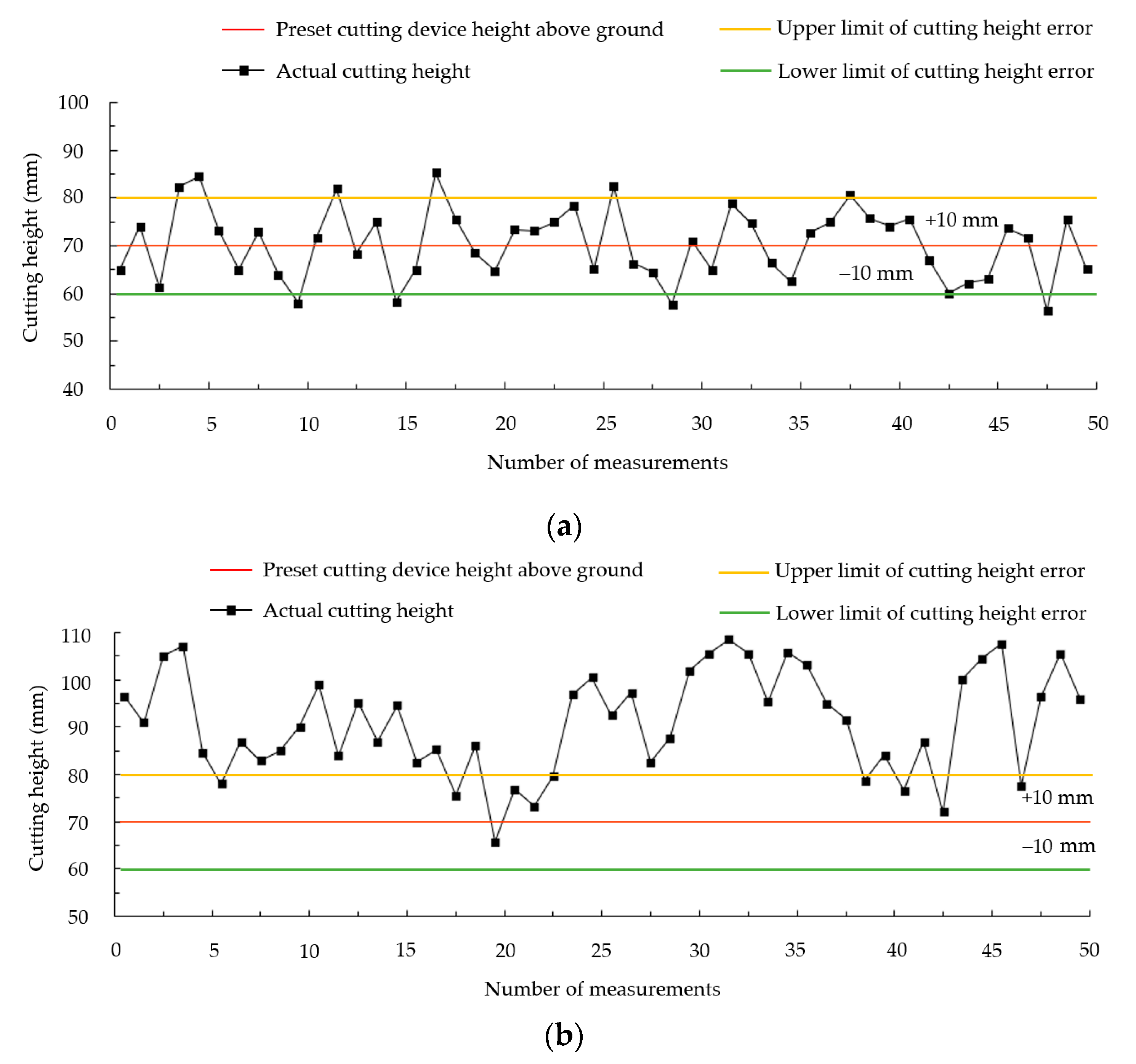
5.3. Analysis of Test Results

The measurement results for header loss rate are shown in Table 2. Under the same operating conditions, the loss rate of the header was 1.34%, which was 55% lower than that of the existing reel-type rigid soybean header. This indicated that the soybean header operation had a good effect and could effectively reduce the header losses.
The actual height distribution of stubble is shown in Figure 12. According to the actual operation requirements, the deviation of stubble height was controlled within the range of plus or minus 10 mm. It can be seen from the figure that when the synchronous profiling cutting device was operated, the stubble height was mostly distributed within the allowed error range. However, when the rigid cutting device of the existing soybean header operated, the distribution of stubble height was mostly beyond the allowable error range, and the control of cutting height was unstable.
By calculating the measurement data of stubble height, it can be concluded that the average stubble height during the operation of the synchronous-profiling cutting device was 70.36 mm, with a maximum deviation of 15.3 mm and an average deviation of 6.38 mm. The average height of the stubble during the operation of the existing rigid cutting device of the soybean header was 90.96 mm, with a maximum deviation of 38.6 mm and an average deviation of 21.14 mm.
Further calculation showed that the stubble height of the synchronous-profiling cutting device designed in this paper was 22.7% lower than that of the existing soybean rigid cutting device. This indicated that the synchronous-profiling cutting device had a good effect on controlling the cutting height, which met the working requirements of the soybean header.

6. Conclusions

(1)
A low-loss soybean header based on synchronous profiling was designed to address the problems of a lack of soybean harvesting machines for supporting soybean-corn strip intercropping, the few existing soybean headers, and the high loss rate of soybean headers.
(2)
In order to realize the cutting device attached to the undulating ground, a synchronous-profiling cutting device was designed. The spring stiffness was determined to be 6 N/mm by theoretical and dynamic analyses. The simulation analysis of the motion process of the synchronous-profiling cutting device was conducted through ADAMS rigid-flexible coupling, indicating that the profiling cutting device can effectively control the height of the cutter off the ground in real-time by following the fluctuations of the ground. The cutting device can respond to the ground excitation accurately and quickly, which meets the requirements of synchronous profiling and low-cutting.
(3)
Field test results showed that the loss rate and stubble height of the soybean header were 1.34% and 70.36 mm, respectively, which were 55% and 22.7% lower than the existing reel-type rigid soybean header and met the requirements of the soybean harvesting operation index.

Author Contributions

Conceptualization, L.Z. and J.N.; methodology, J.N.; software, J.N. and H.L.; validation, J.N., Y.Z., Q.L. and Q.Q.; formal analysis, L.Z.; investigation, L.Z.; resources, J.N.; data curation, J.N.; writing—original draft preparation, J.N.; writing—review and editing, J.N., H.L., Y.Z., Q.L., Q.Q. and L.Z.; funding acquisition, Y.Z. All authors have read and agreed to the published version of the manuscript.

Funding

This research was funded by Sichuan Provincial Department of Science and Technology (2021YFG0063).

Institutional Review Board Statement

Not applicable.

Data Availability Statement

The data presented in this study are available upon request from the authors.

Conflicts of Interest

The authors declare no conflict of interest.

References

  1. Yang, W.; Yang, F. Developing Maize-Soybean Strip Intercropping for Demand Security of National Food. Sci. Agric. Sin. 2019, 52, 3748–3750. [Google Scholar]
  2. Luo, H.; Jiang, X.; Qin, D.; Zuo, P.; Zhang, F.; Zhang, L. Design and Experiment of Narrow Row Spacing and Low-Damage Corn Picking Header. J. Northeast Agric. Univ. 2021, 52, 66–76. [Google Scholar]
  3. Wu, Y.; Gong, W.; Yang, F.; Wang, X.; Yong, T.; Liu, J.; Pu, T.; Yan, Y.; Yang, W. Dynamic of recovery growth of intercropped soybean after maize harvest in maize-soybean relay strip intercropping system. Food Energy Secur. 2022, 11, e350. [Google Scholar] [CrossRef]
  4. Liu, J.; Jin, C.; Liang, S.; Ni, Y. The Research of Soybean Harvested by Machine. J. Agric. Mech. Res. 2017, 39, 1–9+15. [Google Scholar]
  5. Chaab, R.; Karparvarfard, S.; Rahmanian-Koushkaki, H.; Mortezaei, A.; Mohammadi, M. Predicting Header Wheat Loss in a Combine Harvester, a New Approach. J. Saudi Soc. Agric. Sci. 2020, 19, 179–184. [Google Scholar] [CrossRef]
  6. Guo, S.; Xu, J. Development Status and Existing Problems of Soybean Food Industry in China. J. Food Sci. Technol. 2023, 41, 1–8. [Google Scholar]
  7. Luo, Y. On Farm Harvest and Storage Losses of Oil Crops and the Impact on Resources and Environment in China. Chin. J. Oil Crop Sci. 2022, 44, 249–256. [Google Scholar]
  8. Arends-Kuenning, M.; Garcias, M.; Kamei, A.; Shikida, P.; Romani, G. Factors associated with harvest and postharvest loss among soybean farmers in Western Parana State, Brazil. Food Policy 2022, 112, 102363. [Google Scholar] [CrossRef]
  9. Chen, W.; Zhang, M.; Han, Y.; Zhu, J. Investigation on the Mechanical Harvest Loss of Soybean—A case study of soybean in Heilongjiang and Inner Mongolia. Agric. Sci. Eng. China 2017, 29, 16–20. [Google Scholar]
  10. Xia, X.; Yang, G.; Chen, Q.; Song, Z.; Mei, S.; Jin, Y. Analysis on loss reduction technology and strategy for combined harvesting process of food legumes. J. Chin. Agric. Mech. 2022, 43, 13–19+25. [Google Scholar]
  11. Kassen, D.; Kelkar, A. Combine harvester header height control via robust feedback linearization. In Proceedings of the 2017 Indian Control Conference (ICC), Guwahati, India, 4–6 January 2017; pp. 1–6. [Google Scholar]
  12. Tulpule, P.; Kelkar, A. Integrated robust optimal design (IROD) of header height control system for combine harvester. In Proceedings of the 2014 American Control Conference, Portland, OR, USA, 4–6 June 2014; pp. 2699–2704. [Google Scholar]
  13. Ni, Y.; Jin, C.; Chen, M.; Yuan, W.; Qian, Z.; Yang, T.; Cai, Z. Computational model and adjustment system of header height of soybean harvesters based on soil-machine system. Comput. Electron. Agric. 2021, 183, 105907. [Google Scholar] [CrossRef]
  14. Li, Z. Design of Soybean Profiling Header and Control System for Multi-Crop Crawler Combine Harvester. Master’s Thesis, Jiangsu University, Zhenjiang, China, 2022. [Google Scholar]
  15. Jin, C.; Liu, G.; Ni, Y.; Yang, T.; Wang, T.; Qi, Y. Design and experiment of header profiling mechanism for combine harvester based on MBD-DEM coupling. Trans. Chin. Soc. Agric. Eng. 2022, 38, 1–10. [Google Scholar]
  16. Xie, H. Design and Experiment of Belt Conveyor Header for Soybean Combine Harvester. Master’s Thesis, Shandong University of Technology, Zibo, China, 2019. [Google Scholar]
  17. Xu, F.; Zhang, L.; Peng, J.; Yang, H.; Wang, Y. Development status and trend of special machine for soybean and corn strip compound planting. J. Chin. Agric. Mech. 2023, 44, 1–8. [Google Scholar]
  18. Yang, H. Parameters Optimization of Harvester Threshing Unit and Appropriate Agronomic Characteristics of Machine-harvested Soybean in Relay Strip Intercropping. Master’s Thesis, Sichuan Agricultural University, Chengdu, China, 2018. [Google Scholar]
  19. Zhang, B.; Li, Z. A discussion on Lagrange’s equation and its application. J. Shijiazhuang Railw. Inst. 1990, 3, 55–63. [Google Scholar]
  20. Kong, F.; Wang, D.; Shi, L.; Wu, T.; Chen, C.; Sun, Y.; Xie, Q. Design and experiment of disc-cutting picking device of castor. Trans. Chin. Soc. Agric. Eng. 2021, 37, 1–9. [Google Scholar]
  21. Yin, Q.; Li, Y.; Ji, B.; Chen, L. Design and Experiment of Clamping and Conveying Device for Self Propelled Reed Harvester. J. Agric. Mech. Res. 2023, 45, 113–118. [Google Scholar]
  22. Chinese Academy of Agricultural Mechanization Sciences. Agricultural Machinery Manual; China Agricultural Science and Technology Press: Beijing, China, 2007. [Google Scholar]
  23. Ren, L.; Zhang, L.; Ding, G.; Yang, W.; Wang, X.; Yong, T.; Kong, F.; Dai, J. Design and experiment of a type of 2BF-5 maize-soybean strip intercropping precision seeder. J. Henan Agric. Univ. 2019, 53, 207–212+226. [Google Scholar]
  24. Guan, Z.; Jiang, T.; Li, H.; Wu, C.; Zhang, M.; Wang, G.; Mu, S. Analysis and test of the laying quality of inclined transportation rape windrower. Trans. Chin. Soc. Agric. Eng. 2021, 37, 59–68. [Google Scholar]
  25. Ni, Y.; Jin, C.; Wang, T.; Zhou, L.; Liu, Z. Design and experiments of the 4LZ-1.5 soybean combine harvester. Trans. Chin. Soc. Agric. Eng. 2022, 38, 1–11. [Google Scholar]
  26. Chen, Z.; Xue, Z.; Zhang, S.; Li, L. Closing Effort Analysis of Sliding Doors Based on Co-simulation of ADAMS and Simulink. China Mech. Eng. 2020, 31, 924–930. [Google Scholar]
  27. Zhou, J.; Gao, Y.; Wang, D.; Xiao, J.; Wang, Z. Artillery launch dynamic simulation based on ADAMS. J. Vib. Shock 2020, 39, 135–140. [Google Scholar]
  28. Geng, A.; Zhang, M.; Zhang, J.; Zhang, Z.; Gao, A.; Zheng, J. Design and Experiment of Automatic Control System for Corn Header Height. Trans. Chin. Soc. Agric. Mach. 2020, 51, 118–125. [Google Scholar]
  29. Wang, Y.; Fang, L.; Zhou, S. Design of Bionic Variable Stiffness Joint. Trans. Chin. Soc. Agric. Mach. 2018, 49, 390–396. [Google Scholar]
  30. Shi, Y.; Chen, X.; Chen, M.; Wang, D.; Shang, S. Design and Experiment on Ploughshare Furrowing Ridging Device of Sweet Potato Ridging Shaping Machine. Trans. Chin. Soc. Agric. Mach. 2022, 53, 16–25. [Google Scholar]
Figure 1. Soybean and corn planting patterns.
Agriculture 13 01580 g001
Figure 2. Structure diagram of a low-loss soybean header based on synchronous-profiling. (1) Power input shaft, (2) profiling spring, (3) guide column, (4) profiling plate, (5) reciprocating low-position single-action cutter, (6) flexible reel conveyor belt, and (7) divider.
Agriculture 13 01580 g002
Figure 3. Structure drawing of a synchronous-profiling cutting device. (1) Churning, (2) flexible reel belt, (3) upper profiling spring, (4) guide column, (5) profiling device support, (6) lower profiling spring, (7) guide post support, (8) profiling plate, and (9) cutter.
Agriculture 13 01580 g003
Figure 4. Dynamic model of a synchronous-profiling cutting device. Point O is the coordinate origin; point A and point C are the original working points of the profiling device and the maximum point of displacement of the profiling device; point B is the position of the center of mass of the profiling device; h, Δ h , and y1 are the original height of the profiling device, the displacement distance when profiling, and the displacement distance of the center of mass of the profiling device in mm; l1 is the distance from the center axis of the guiding column to the center line of the profiling plate in mm; l2 is the distance from the center axis of the profiling plate to the center of mass in mm; FN is the force of the ground on the profiling plate, N; Ff is the friction force of the ground on the profiling plate, N; Ft1 and Ft2 are the lower profiling spring force and the upper profiling spring force, N; v B is the velocity of the center of mass movement during the profiling motion, m/s.
Agriculture 13 01580 g004
Figure 5. Flexible reel-belt conveyor device. (1) Driven wheel, (2) support wheel, (3) flexible reel belt conveyor, and (4) main wheel.
Agriculture 13 01580 g005
Figure 6. Clamping conveying force analysis diagram. L1 is the distance from the center of gravity of the cut plant to the cutting point, mm; L2 is the distance from the bottom surface of the belt to the cutting point, mm; FA is the force of the front reel teeth on the plant, N; FO is the force of the rear reel teeth on the plant, N; m is the space between the teeth of the belt, mm; h is the height of the teeth of the belt, mm; α is the angle between the spacing between the teeth of the belt and the height of the teeth, (°); θ is the inclination angle between the plant and the belt, (°); Point A is the point of action of the front reel teeth on the plant; Point O is the point of action of the rear reel teeth on the plant; Point B is the point of center of gravity of the plant; G is the gravity force of the cut plant, N; and Point C is the intersection point of the three forces.
Agriculture 13 01580 g006
Figure 7. Simulation model of a synchronous-profiling cutting device.
Agriculture 13 01580 g007
Figure 8. Profiling change curve of the synchronous-profiling device attached to the ground. (a) Profiling curve at 0.9m/s forward speed; (b) Profiling curve at 1.2 m/s forward speed; (c) Profiling curve at 1.4 m/s forward speed.
Agriculture 13 01580 g008
Figure 9. Profiling device subsidence. (a) Sinkage of the profiling device at a forward speed of 0.9 m/s; (b) Sinkage of the profiling device at a forward speed of 1.2 m/s; (c) Sinkage of the profiling device at a forward speed of 1.4 m/s.
Agriculture 13 01580 g009
Figure 10. Test site and equipment.
Agriculture 13 01580 g010
Figure 11. Soybean harvesting effect.
Agriculture 13 01580 g011
Figure 12. The actual height distribution of stubble. (a) Stubble height distribution of synchronous-profiling cutting devices; (b) Stubble height distribution of rigid cutting devices for existing soybean headers.
Agriculture 13 01580 g012
Table 1. Main technical parameters of the header.
No.ParameterValue
1Chassis type4LZ
2Matching engine power (kW)44.2
3Overall dimensions (mm × mm × mm)4230 × 1500 × 2300
4Overall machine mass (kg)2410
5Header width (mm)1300
6Number of rows2
7Operating efficiency (hm2/h)0.27–0.48
Table 2. Measurement results of the header loss rate.
Performance ParameterTest NumberAverage Value of the TestPerformance Index of the Existing Reel-Type Rigid Soybean HeaderTechnical Requirement
123
Header loss rate (%)1.261.441.331.342.98≤3
Disclaimer/Publisher’s Note: The statements, opinions and data contained in all publications are solely those of the individual author(s) and contributor(s) and not of MDPI and/or the editor(s). MDPI and/or the editor(s) disclaim responsibility for any injury to people or property resulting from any ideas, methods, instructions or products referred to in the content.

