Article

Design and Experiment of Sweet Potato Ridging and Forming Machine

1
Chinese Academy of Agricultural Mechanization Sciences Group Co., Ltd., Beijing 100083, China
2
State Key Laboratory of Soil Plant Machine System Technology, Chinese Academy of Agricultural Mechanization Sciences Group Co., Ltd., Beijing 100083, China
3
College of Mechanical and Electrical Engineering, Qingdao Agricultural University, Qingdao 266109, China
*
Author to whom correspondence should be addressed.
Agriculture 2023, 13(8), 1641; https://doi.org/10.3390/agriculture13081641
Submission received: 1 August 2023 / Revised: 14 August 2023 / Accepted: 17 August 2023 / Published: 21 August 2023
(This article belongs to the Special Issue Agricultural Machinery Design and Agricultural Engineering)

Abstract

:
To address the problem of poor ridging effect, a sweet potato ridging and shaping machine was designed and its overall structure and working principles were described. The design parameters of rotary tillage device, furrowing and shaping device and pressing and shaping device were determined. The motion model of soil particles on the furrowing and shaping device was analyzed, the force model of the furrowing and shaping device was established. A response surface Box–Behnken Design test was carried out to obtain the better working parameters of the sweet potato ridging and shaping machine as follows: the embedded depth is 196 mm, the forward speed is 0.82 m/s, and the soil moisture is 18%. At this time the stability coefficient of the ridge height was 99.84%. The comparative test showed that the operation performance and fuel consumption of the ridge shaping machine were better than 1GQL-2 sweet potato two rows rotary plowing and ridging machine, which met the agronomic requirements and created a good soil environment for sweet potato. The research can provide a design reference for the development and application of sweet potato transplanting machinery and ridging machinery in hilly areas.

1. Introduction

Sweet potato is an important food crop in China, and its planting area is about 3.36×10⁶ hm2, ranking first in the world [1]. The sweet potato production areas are mainly concentrated in the southwest region and east China, and more than half of the sweet potato in the country is produced in these two regions. As a specialty food crop, sweet potato has many production links, usually transplanted after ridging. Currently, the ridging and shaping process can basically finished by machine, but the existing machine is difficult to meet the agronomic requirements of sweet potato, especially the height of the ridge and the soil compactness, affecting the sweet potato transplanting operations and future field management [2,3].
A lot of research has been carried out on ridging operation. Dai et al. [4,5,6] developed a horizontal belt mulching type full-film double-row furrow mulching machine for the whole-film double-row furrow sowing planting in the dry land of Northwest China. It can complete the longitudinal and transverse laying of ridging, fertilizer application, spraying, mulching and mulching belt on the film at one time; Lin et al. [7] designed 1MXQ-4 stubble rotary plowing and ridging machine can complete the joint operation of subsoil tillage, stubble, rotary plowing, ridging and suppression, and at the same time, it can realize the exchange of furrow and ridge hathpace. Bao et al. [8] designed a plow rotary combination oilseed rape furrowing and ridging machine, using the plowshare furrowing component for furrowing and ridging operations, compared with the traditional ridging plow, the soil fall back problem has been significantly improved. Wang et al. [9] designed a carrot seeding machine, the use of double-wing ploughs and compression rollers combination of ridging and shaping device, by first turning the soil and then compression to form a ridge; Fu et al. [10] designed corn stubble fertilizer ridging machine adopts a compound type of ridging method. Realize stubble and directional soil throwing, and further through the mulcher and spade soil cultivator to rise the ridge operation. Suppressor roller ridge top suppression to form a trapezoidal ridge; Li et al. [11] designed a Machine Integrating Ridge-Breaking, Fertilizing, and Ridging for Ratoon Sugarcane, the use of crushing, rotary tillage and pressing to form a ridge, and the realization of the device into the soil depth can be adjusted. The depth of the device is adjustable. Zhang et al. [12,13,14] designed 2BFQ-6 oilseed rape combine direct seeder adopts a boot-type opener, and the side plates of the boot-type opener and the leveling drag plate press the soil to form a ridge at the same time. Poland WEREMCZUK company [15] designed and produced integrated AUR2, integrated AUR4 rotary plowing and shaping machine, integrated rotary plowing and soil crushing and shaping function, through the hydraulic drive shaping rollers to form a ridge. US Veda Farming Company [16] produces and designs G35 multifunctional reversing rotary tiller, which also integrates the functions of rotary tillage and soil crushing and ridging and shaping, and the rear compression and shaping device can be changed to other devices according to the operational requirements.
At present, China’s sweet potato ridging operation has also carried out targeted research, Wang et al. [17] designed a 1GQL-2 sweet potato double ridging and mulching machine, the use of single-wing ridging plows and lateral sealing guards, can realize a two-row operation, with rotary plowing, ridging, suppression, etc., high operating efficiency; Liu et al. [18] developed a 1KQ-30 sweet potato ridging machine, whose ridging mechanism consists of composite soil feeder and scraper, and at the same time, it has the function of rotary tillage and ridging and shaping, and the rear pressing and shaping device can also be replaced with other devices according to operational requirements. Its ridging mechanism consists of compound soil feeder and scraper, and at the same time, it increases the rotary plow crushing knife roller between the disc surface knives, which can solve the problem of uneven soil crushing during the ridging operation. Because the agronomic requirements of sweet potato differ greatly from the rest of the crop, the research on various ridging machinery can only be used as a reference and cannot be used directly. And the existing sweet potato ridging machinery has problems such as easy collapse of the ridge and small ridge height, which restricts the development of sweet potato industry.
To address the above problems, designs a sweet potato ridging and shaping machine. Combined with the sweet potato agronomic requirements, the design scheme and the main technical parameters of the sweet potato machine are determined. Rotary tillage device, furrowing and ridging device and pressing and shaping device were designed, and the structural parameters of each device were determined. The field test verified that the performance and economy of the sweet potato ridging and shaping machine are better than the existing sweet potato ridging machine, which can meet the agronomic requirements of sweet potato. It creates a good soil environment, improves sweet potato yield, and is of great significance in promoting the development of sweet potato industry.

2. Materials and Methods

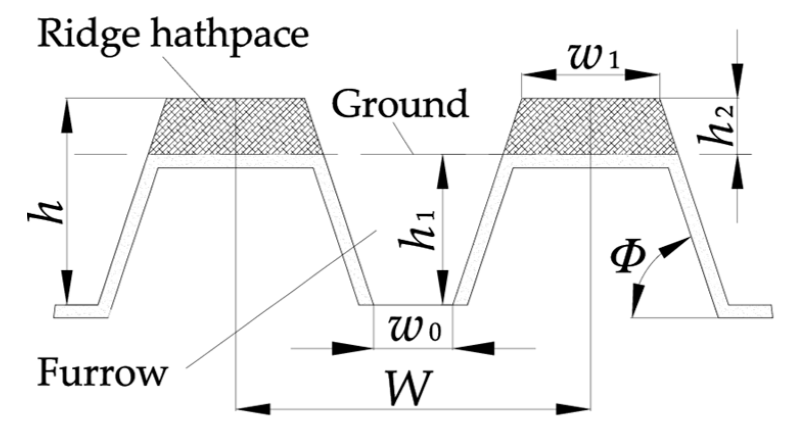
2.1. Agronomic Requirement

Sweet potato planting patterns in China vary greatly from region to region, but most of them are planted in ridged rows. There are two types of planting patterns: double rows on large ridges, double rows on double ridges and single rows on single ridges. At present, there is no research showing that different planting modes will influence the yields and qualities of sweet potato. Sweet potato planting ridge body requires a larger height of the ridge body, the difficulty of ridging and cannot be common with the rest of the crop machinery, so the study of sweet potato ridging and shaping machinery is very necessary.
The Sweet potato ridge type in production is mainly divided into trapezoidal and semicircular ridges, of which trapezoidal ridges are suitable for mechanized ridging and shaping operations, then trapezoidal ridges were selected as the planting ridge type. Through visiting the production areas and considering the conditions of the local fields and agronomic requirements, the trapezoidal ridge planting pattern with two rows on two ridges was selected. The specific parameters of the pattern were as follows [19,20]: bottom width of 600 mm, top width of 400 mm, furrow width of 200 mm, height of 250 mm, and spacing of 800 mm.

2.2. Overall Structure and Working Principles

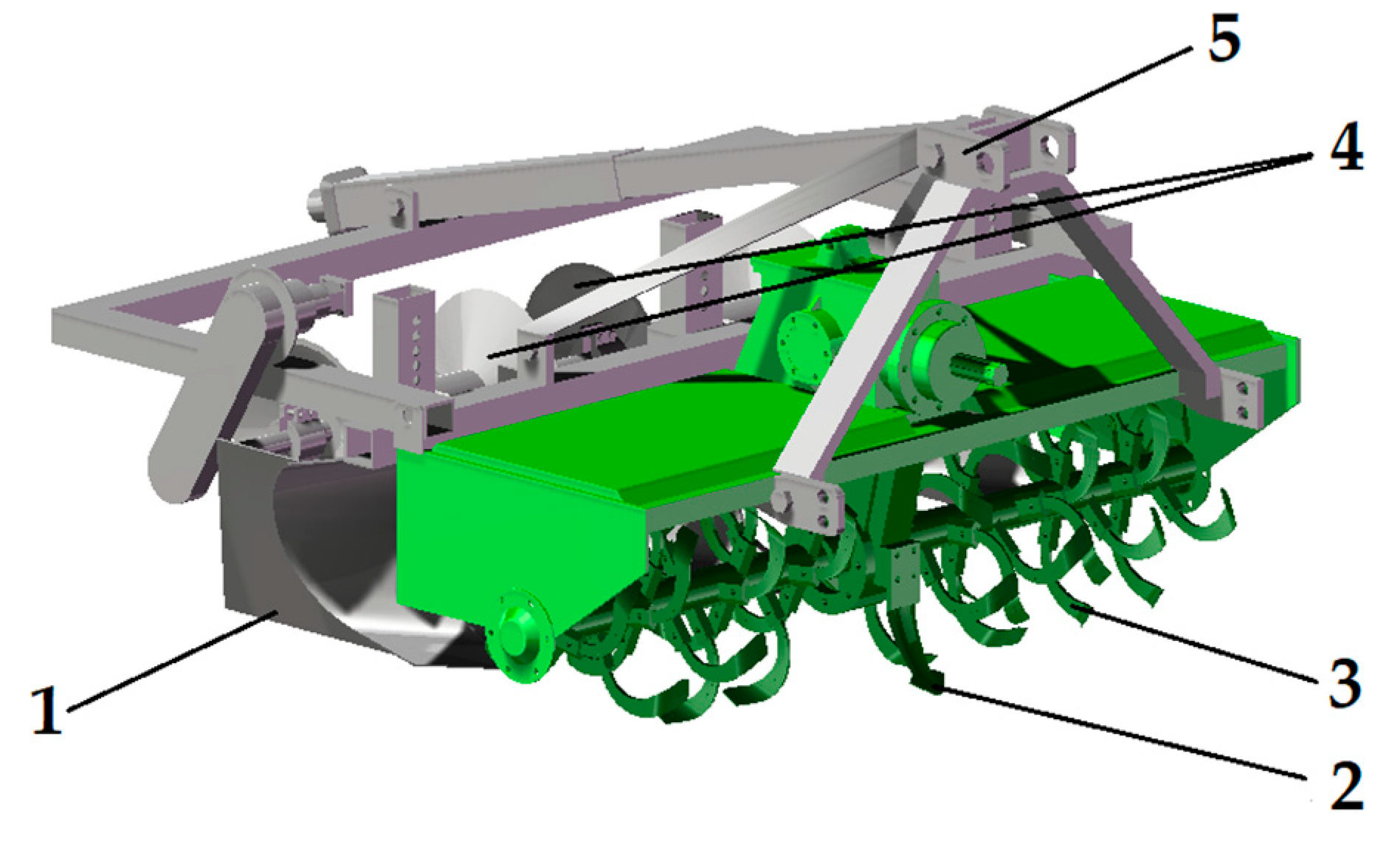
2.2.1. Overall Structure

Sweet potato ridging and shaping machine is a joint operation machine which is drawn by tractor, powered, and hydraulically driven. The whole machine mainly consists of frame, three-point suspension, gearbox, rotary plow blade, and Pressing shaping roller and other devices. To facilitate the design, this paper divides the whole machine structure into three devices: Rotary tillage device, plowshare furrowing device and pressing and shaping device, as shown in Figure 1.

2.2.2. Working Principle

The tractor driven shaft drives the Front plow at the front of the machine to cut the soil in the unplowed area and guide the machine to enter the soil smoothly. The rear output shaft delivers the power to the gearbox through the universal joint coupling, rotate the Rotary cutter, which achieves the effect of soil crushing through the cutting, throwing, and collision with the implement of the soil, and gathers the soil that has been crushed to the middle. Plowshare furrowing and ridging device moves forward together with the implement, and the soil moves upward along with the guiding effect of the Furrowing plow, and then leaves the surface of the Furrowing plow under the action of speed and gravity when it reaches the ground and piles up into a ridge of soil at the edge of the Ridge surface, completing the furrowing and guiding soil operation. Presses the Ridge side to form a preliminary ridge. The Pressing and shaping device are used to trim and compact the ridge, forms the ridge shape meet the requirements of sweet potato planting.

2.3. Key Components Structural Parameters Determination

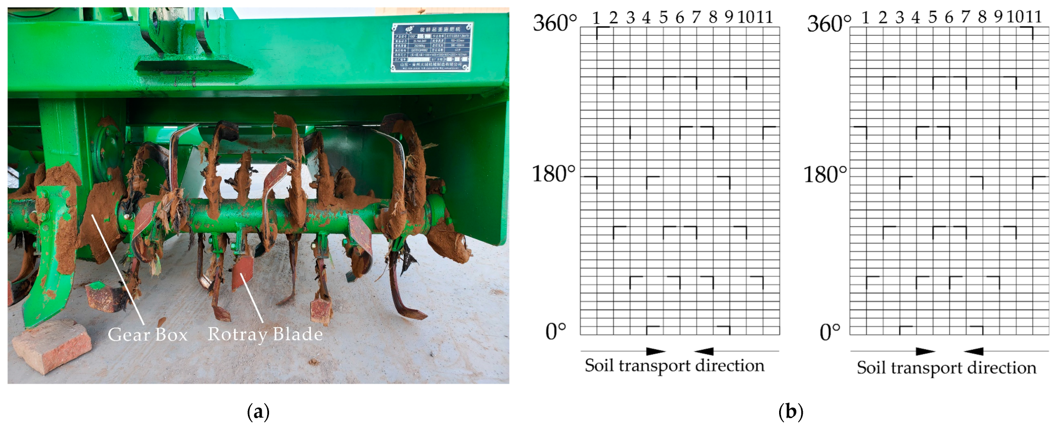
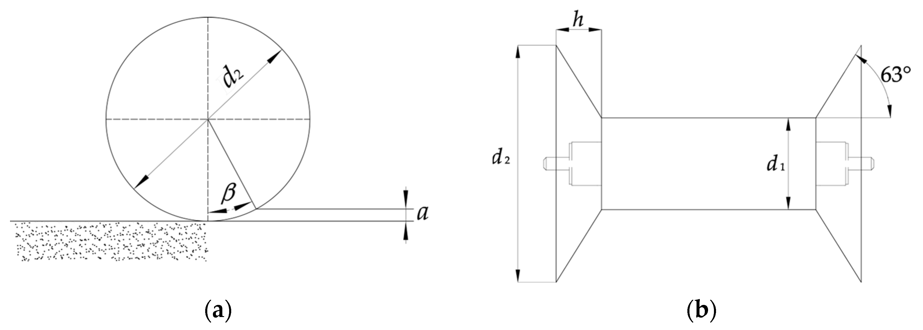
2.3.1. Rotary Tillage Device

The Rotary tillage device is symmetrically distributed on the left and right, and while completing the soil crushing operation, it gathers the soil within the width of a single side to the center, so that there is enough soil volume when starting the ridge. To realize the function of soil delivery to the middle, a method of installing the rotary tillage blades in the same rotation plane in the same direction is designed. That is, the left blade shaft adopts the right helix arrangement, and the cutting soil is thrown to the right rear during the operation, and the right blade shaft adopts the left helix arrangement, and the cutting soil is thrown to the left rear during the operation, to realize the purpose of soil conveying to the middle. The tillage blade in the middle of the blade roller adopts normal arrangement and throws to the right rear, meanwhile, the Rotary tillage blades near the position of the gearbox and the position of the two side panels of the implements are selected to select the type of rotary tillage blades with larger rotary tillage radius and larger tillage depth, and all adopt normal arrangement, as shown in Figure 2, with the purpose of carrying out rotary tillage and crushing operation on the soil at the bottom of the gearbox and at the bottom of the two side panels of the implement at the same time, to reduce the traction resistance.
The left and right Blade rolls of the rotary plow device are 11 pairs, totaling 22 rotary blades. The rotary Blade rollers are arranged in a double spiral, the angle between the blades on the same spiral line is 60°, and the spacing between the Blade rollers is 75 mm, as shown in Figure 3. To achieve the plowing depth and width required by the agronomy of sweet potato planting, with reference to GB/T 5669-2017 Rotary Tillage Machinery Blades and Holders, the inner rotary blades are selected as IT245 rotary blades, and the outer rotary blades are selected as IT260 rotary blades [21].

2.3.2. Pressing and Shaping Device

The Pressing and shaping rollers are symmetrically arranged, and the two pressing and shaping rollers correspond to the two ridge bodies, with their midline aligned with the centerline of the ridge to ensure uniform impact the ridge surface. Pressing and shaping roller is cylindrical design, wider surface to make the pressure distribution uniformly. Pressing shaping roller is mainly composed of drive shaft, compaction shaping roller and molding plate, when the operation relies on the tractor to drag the ridge shaper forward and its own rotation to compact the soil on the upper part of the ridge, reduce the loss of water in the soil as well as to achieve the role of heat preservation and moisture retention, and through the molding plate on the two sides of the trapezoidal shape of the ridge is sorted out. Under the same soil conditions, the larger the diameter and width of the pressing and shaping roller, the smaller its rolling resistance and soil resistance [22]. However, the larger diameter and width will increase the size of the Pressing and shaping device, but also will cause excessive pressure on the drive system. Therefore, to ensure the performance, control the diameter of roller, the minimum diameter should be satisfied:
d 2 a 1 cos β
where d is the diameter of pressing and shaping roller, mm; a is the depth of pressing, mm; β is the flip angel of pressing and shaping roller°.
To ensure the normal operation of the pressing and shaping roller, pressing and shaping roller flip angle β should be satisfied with less than or equal to 20°, the formula to take β = 18°, take depth of pressing a = 30 mm, the diameter ≥123 mm, taking into account the performance, pressing and shaping roller diameter is determined to be 200 mm. The smooth surface design can reduce the adhesion of the soil in the pressing and shaping roller.
The molding disk at both sides of the pressing and shaping roller is to trim out the trapezoidal target ridge pattern, and the angle of inclination at both sides should be the same as the angle of inclination of the ridge body, with reference to the agronomic planting requirements of the ridge pattern, take the angle of inclination of 63°. As shown in Figure 3, the outer diameter of the molding disc should be designed considering the height of the loose soil in the ridging process and three-side of ridge can be pressed simultaneously. The parameters of the designed pressing and shaping roller are pressing and shaping roller diameter d1 = 200 mm, molding disc outer diameter d2 = 550 mm, height h = 140 mm.
Figure 3. Schematic diagram of pressing and shaping roller. (a) Cross-scetional of pressed soil. (b) Front of pressing and shaping roller d2 is outer diameter of molding disc; β is pressing and shaping roller flip angle; d1 is diameter of pressing and shaping roller; h is height of molding disc; a is depth of pressing.
Agriculture 13 01641 g003

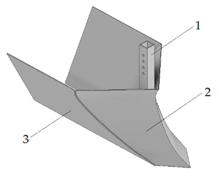
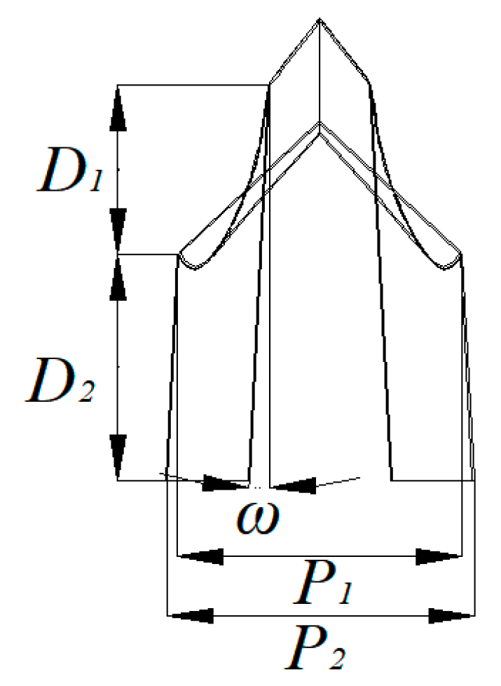
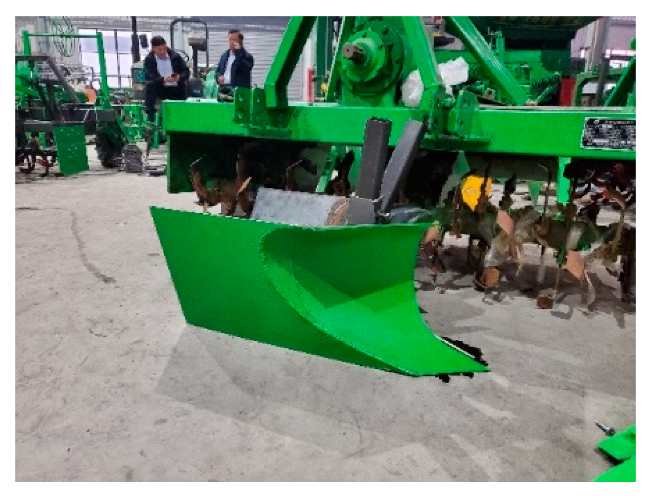
2.4. Design of Plowshare Furrowing and Ridging Device

Plowshare furrowing and ridging device mainly consists of furrowing surface, wing plate and connection frame, connection frame can adjust the depth of the Plowshare furrowing and ridging device into the soil, and the wing plate is a plate-like structure. The overall structure is shown in Figure 4.
When working in the field, as the Sweet potato ridging and shaping machine advances, the lower part of the furrowing surface cuts the soil and lifts the soil to the middle part of the surface; the soil is divided into two sides in the middle part of the surface and lifted to the upper part of the surface which is higher than the ground; the upper part of the surface guides the soil to be turned over and thrown to the top of the ridge and flattened. The wing plate is narrow in the front and wide in the back, the narrowest part relates to the furrowing surface and gradually widens outward with the forward direction. The wing plate will impact the two sides of the ridge to form a ridge after furrowing, and at the same time guides the soil at the ridge surface to prevent the soil from falling back into the furrow.
Parameters of the ridge are bottom width of 600 mm, top width of 400 mm, furrow width of 200 mm, height of 250 mm, spacing of 800 mm. During the working process of sweet potato ridging and shaping machine, the furrowing surface lifts the soil in the ridge to the ridge and separates the soil to the two sides, and finally stabilizes it at the ridge surface under the impacting of the wing plate to achieve the soil exchange between Furrow and Ridge hathpace [7], the ridge cross section is shown in Figure 5.
In Figure 5, with Ridge hathpace above the ground and Furrow below the ground. ridge inclination ϕ can be expressed as:
ϕ = arctan h 1 2 ( W w 0 ) w 1
where h is the height of ridge, mm; W is the spacing between ridges, mm; w0 is the furrow width, mm; w1 is the top width, mm.
After the soil has been rototilled and broken up, the soil volume will be fluffed up, and the minimum embedded depth of the furrowing surface can be expressed as follows:
h 1 = λ w 1 + w 1 + h 2 cot ϕ × h 2 w 0 + w 0 + h 1 × cot ϕ
where h is the volume ratio of soil before and after rototilled, taken as 1.2; h2 is the height of ridge hathpace, mm;
With the parameters of the ridge, the angle of inclination of the ridge was calculated to be 63°, and the theoretical minimum embedded depth was 192 mm.
Considering the soil be fluffed up, soil accumulation in the forward of the plowshare furrowing and ridging device, etc., the height of the plowshare furrowing and ridging device should be higher than the height of soil accumulation of ridge surface, the top width of the plowshare furrowing and ridging device can be expressed as:
W k = w 0 + 2 H k cot ϕ λ
where Wk is the top width of plowshare furrowing and ridging device, mm; Hk is the height of plowshare furrowing and ridging device, mm.
With the parameters of the ridge, Wk was determined to 670 mm, Hk was determined to 410 mm.

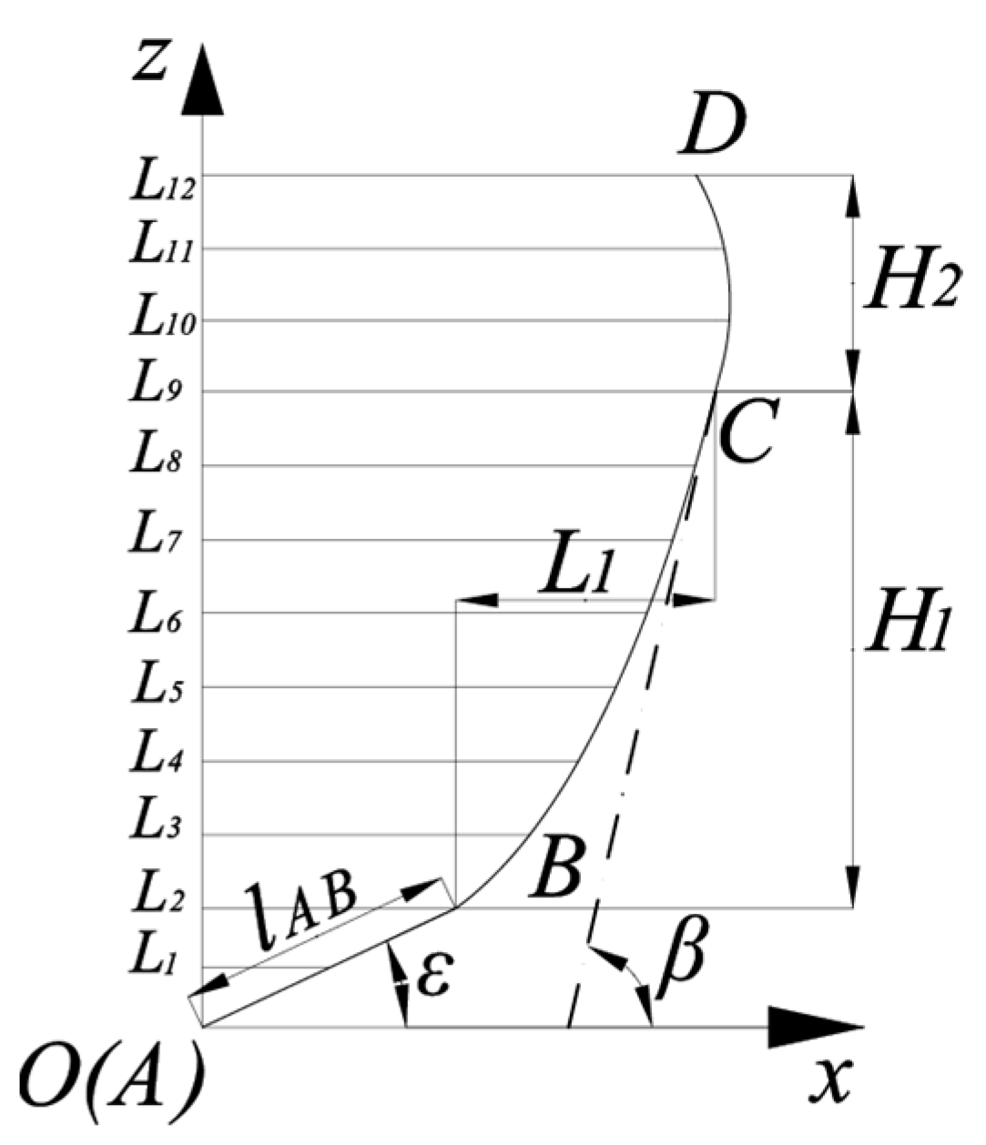
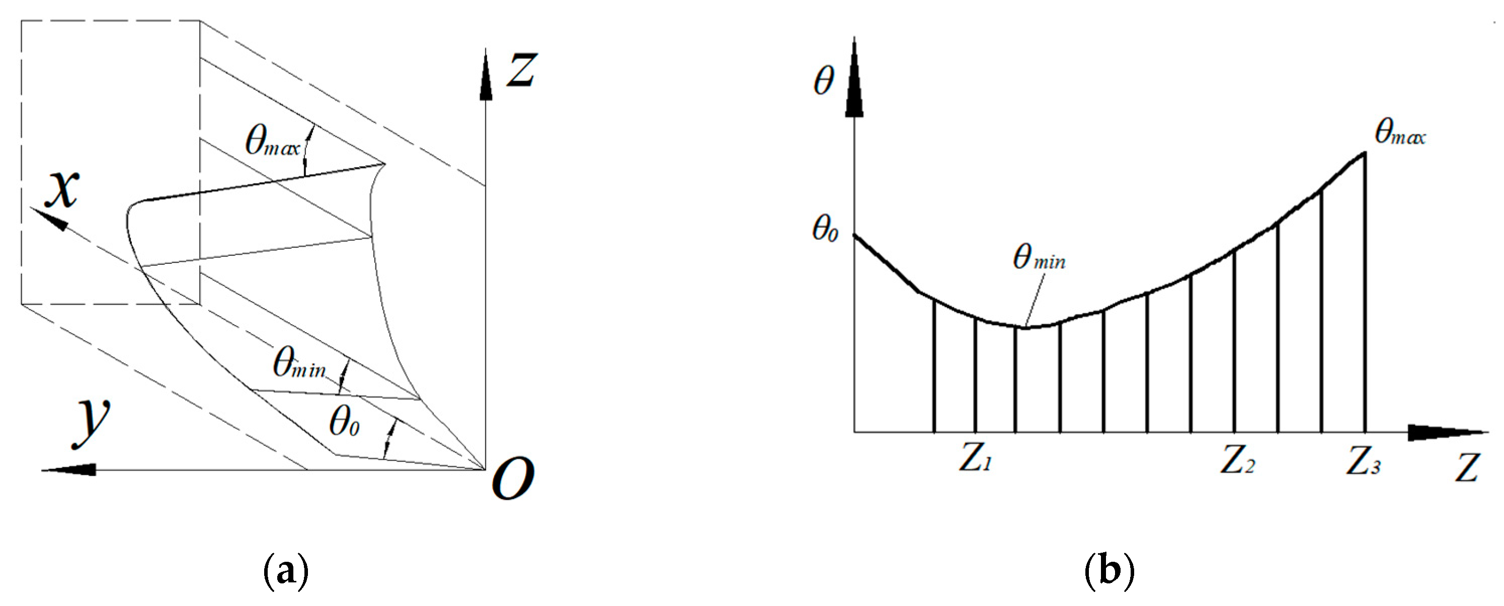
2.4.1. Design of Furrowing Surface

The furrowing surface is regarded as horizontal straight-line formed along the Guiding curve motion, and the angle between the horizontal straight-line and the guiding curve is a certain rule of change, the guiding curve consists of the beginning of the straight-line AB, the curve section BC below the Ground and the curve section CD above the Ground [23]. The endpoints A (0, 0), B(xb, zb), C(xc, zc), D(xd, zd) are transitioned smoothly, and the guiding curve is shown in Figure 6.
The parametric equation of the Guiding curve can be expressed as:
f ( x ) = k x a x 2 + b x + c R 2 x 2 + d
where k, a, b, c, d are constants, R is the arc radius of curve section CD, mm.
The parameter equation of the guide curve is determined by the slope of the AB section, i.e., the installation angle ε and lAB, the height of the BC section H1 and the openness L1, and the height of the CD section H2. According to the requirements of sweet potato planting operation, the values of the guide curve parameters of the furrowing surface are as follows: the installation angle ε is taken as 25°, lAB is taken as 85 mm, the openness L1 of the section BC is taken as 150 mm, the height H1 of section BC is taken as 245 mm, the height H2 of the section CD is taken as 125 mm, and the radius of the section arc is taken as 150 mm [24]. the slopes of the guide curve endpoints B and C can be expressed as follows:
tan α = k = 2 a + b tan β = 2 b x c + c = x c R 2 x c 2
Calculate the Equations (4) and (5) jointly:
k = tan a a = H 1 L 1 tan a x b + x c 2 L 1 b = tan a 2 H 1 L 1 tan a x b + x c 2 L 1 c = z c a x c 2 + b x c d = z c x c 2 b x c + b
Substituting the parameters of the sections of the Guiding curve gives k = 0.47, a = 0.05, b = 0.37, c = 2.2 and d = 16.8.
Plowshare furrowing and ridging device is arranged after rotary tillage device breaks up the soil, mainly completes the soil guide and soil turning, the Semi-spiral curved surface turns up the soil with better performance [24]. Therefore, the furrowing surface adopts the Semi-spiral curved surface. The Element line angle θ grows slowly in the lower part of the furrowing surface and grows faster in the upper part of the furrowing surface. The initial Element line angle is also the angle between the furrowing surface and the furrow side, which is the bulldozing angle. To reduce the tractive resistance and avoid excessive soil disturbance, the initial Element line angle θ0 is taken to be smaller, and to facilitate the soil to rise, the Element line angle θ0 is taken to be 35°, which is gradually reduced to θmin with the increase in height. In the guiding curve where the AB section meets the BC section, the Element-line angle decreases to θmin. Subsequently, the Element line angle θ increases continuously with the height of the guide curve to θmax.
The difference between the maximum and minimum value of the Element line angle of a Semi-spiral curved surface is generally between 7° and 15°, It has been shown that when the difference in the Element line angle of the semi-spiral surface is greater than 10°, the furrowing surface can achieve the function of soil turning and throwing. However, at the same time, excessive value of the Element-line angle difference will lead to increasing of traction resistance, principle of surface formation is shown as Figure 7a.
The curve of variation of the Element line angle of the furrowing surface takes a concave parabola as shown in Figure 7b and can be expressed as:
θ n = θ min + Δ θ L n 2 L 2 n = 1 , 2 , , 10
where θn is the value of the Element line angle at the nth height, °; θmin is minimum value of the Element line angle, °; θmax is maximum value of the Element line angle, °; Ln is nth height of Guiding curve, mm; L is total height of section BC and CD of Guiding curve, mm.

2.4.2. Design of Wing Plate

After the furrowing surface operation, it is necessary to compact the side of the ridge to prevent part of the soil in the ridge from falling back into the ridge. To solve this problem, a wing plate extending toward the rear of the implement is designed and installed on the side of the furrowing and starter surface to carry out compaction and molding operations on the side of the ridge, as shown in Figure 8.
Considering the soil collapse and fluffing problem after the furrowing surface, the wing plate adopts the front narrow back wide type design, the front width P2 is the same as the top width of the plowshare type furrowing and ridging device, and the rear width P2 has an angle of tilt ω compared with the front width, which is taken as 3° for comprehensive consideration. The height of the wing plate is the same as the height of the furrowing surface. The length of the wing plate consists of two parts, the length of the front part D1 is only related to the parameters of the furrowing surface, and the length of the rear part D2 is related to the forward speed of the sweet potato ridging and shaping machine and the height of the ridge body.
The trajectory of the soil particles during their descent to the ridge is:
D 2 = V Z 2 + 4 g h V x V x 2 g V z = g t h L = 1 2 g t 2
where Vx is the Velocity of soil particles in the forward direction, m/s; Vy is the Velocity of soil particles in the vertical direction, m/s; g is gravitational acceleration, m/s2; t is the drop time of soil particles, s.
The motion speed Vx of soil particles in the forward direction is the same as the forward speed of the machine, which is taken as 0.8 m/s. The falling height h of the soil particles is slightly larger than the height of the plowshare furrowing and ridging device, which is taken as 410 mm, and the length of the back of the wing plate, D2, is calculated to be 270 mm according to the Equation (9).

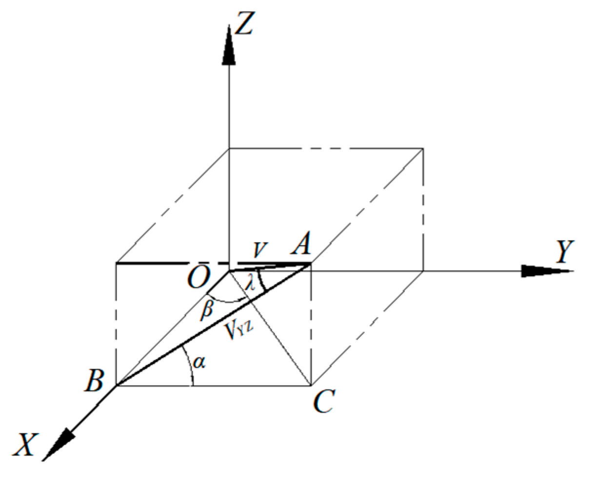
2.4.3. Soil Kinematics Analysis

The motion of soil in the process of operation is extremely complex, to analyze its motion process, according to the structure of furrowing surface, the motion process of soil is divided into two phases: (1) the motion of soil on the furrowing surface; (2) Soil motion after leaving the furrowing surface.
(1)
Soil motion on the furrowing surface.
Soil in the furrowing plow body on the surface of the trajectory can be called the soil track line, if the known soil track line can be obtained from the absolute motion of soil particles and the spatial position at any time and the speed of the size, direction and so on. Among many factors, the greatest influence on the soil track line is the forward speed of the plowshare furrowing device, i.e., the forward speed of the machine. In order to further study the soil trace line, a cubic polynomial is used to describe the equation of the soil trace line, and the coordinates of individual soil particles when they enter and leave the furrowing surface set to be x1, y1, z1 and x2, y2, z2, then the equation of the soil trace line is:
x = V 0 t y = A 0 + A 1 x + A 2 x 2 + A 3 x 3 z = B 0 + B 1 x + B 2 x 2 + B 3 x 3
where V0 is the Velocity of sweet potato ridging and shaping machine, m/s; t is time, s.
The equations in Equation (10) can all be viewed as projections of the soil motion trajectory in the coordinate plane. Therefore, the slope of each projected surface can be obtained by taking the derivative with respect to x:
y = 3 A 3 x 2 + 2 A 2 x + A 1 z = 3 B 3 x 2 + 2 B 2 x + B 1
Bringing x1, y1, z1 and x2, y2, z2 into Equations (12) and (13).
x 1 3 x 1 2 x 1 1 x 2 3 x 2 2 x 2 1 3 x 1 2 2 x 1 1 0 3 x 2 2 2 x 2 1 0 A 1 A 2 A 3 A 4 = y 1 y 2 y 1 y 2
and
x 1 3 x 1 2 x 1 1 x 2 3 x 2 2 x 2 1 3 x 1 2 2 x 1 1 0 3 x 2 2 2 x 2 1 0 B 1 B 2 B 3 B 4 = z 1 z 2 z 1 z 2
From the system of two equations, two sets of coefficients, A and B, can be solved and brought in to obtain the trajectory of the soil on the surface.
(2)
Soil motion after leaving the furrowing surface.
When the soil moves along the furrowing surface to the top or edge of the surface, it is about to be thrown by the surface and leave the surface. At this point, if the internal friction and adhesion between soil particles are ignored, the motion of soil particles can be regarded as an ejection motion.
As shown in Figure 9, when the soil particles move to point A, their spatial position is determined by XA, YA and ZA. In general, we believe that the relative velocity of the soil and the plow body is the forward velocity V of the plowshare furrowing and starting device, and what determines the trajectory of the soil after detaching from the surface of the furrowing and plowing body is the magnitude and direction of the projection VYZ of V in the plane of YOZ. α is the angle of VYZ with the Y-axis, and β is the angle of VXY with the X-axis, and in the case of known α and β, the lateral partial velocity can be obtained by the velocity triangle VYZ. In the figure, OA is the forward speed V of the plow body, AB is the lateral partial velocity VYZ, and λ is the angle between V and VYZ.
Derived from the geometric relationship of △OAB:
V Y Z = V 1 + cos   2   α cot 2 β
Equation (14) shows the relationship between the lateral partial velocity VYZ and the forward velocity V0. The motion of the soil particles after leaving point A is projected in the YOZ plane as a projectile motion, which starts from point A with initial velocity VYZ and α angle to the diagonal rear. In summary, the motion trajectory of soil particles leaving the furrowing surface at point A is:
Z = Y tan α Y 2 g 2 V Y Z cos α
where Z, Y are the coordinate values of soil particles in the YOZ plane; g is gravitational acceleration, m/s2.
As can be seen from Equation (15), the soil motion trajectory of the soil particles after leaving the furrowing surface is related to both the forward speed V0 of the Plowshare furrowing and ridging device, and the angle α between V0 and both the X-axis and Y-axis. Where the value of the angle α is related to the structural parameters of the furrowing surface.
Soil kinematics analysis can only represent the motion trajectory of soil on a surface in an ideal state. In the actual field operation, it is difficult to analyze the actual motion trajectory due to the complex soil environment and the non-ideal shape of the surface. In the next section, this paper intends to explore the soil motion pattern through EDEM (discrete element simulation software)simulation experiments and field verification tests.

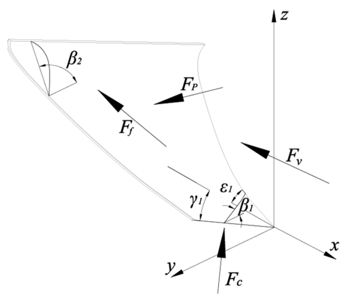
2.4.4. Force Analysis of Furrowing Surface

The traction resistance F1 of the furrowing surface in the forward direction consists of the following components: (1) FC: The cutting force of the surface on the soil; (2) FP: The total pressure of the soil; (3) Ff: The frictional resistance between the soil and surface; (4) Fv: The force driving the soil motion [25]. The direction of the force is shown in Figure 10.
F 1 = F C + F P + F f + F v
(1)
The cutting force FC of the surface on the soil.
The component forces N1 and T1 of the cutting force of the surface on the soil:
N 1 = 7.2 × cos 2 δ sin γ 1 ε 1 π 2 sin ε 1 + f sin γ 1 cos 2 ε 1 1 sin 2 γ 1 sin 2 ε 1 N 2 = 3.6 × sin 2 δ tan γ 1 ε 1 π 2 ρ ε 1 sin 2 γ 1 sin 2 ε 1 d ε
where ε1 is installation angle, °; γ1 is bulldozing angle, °; ρ = ρ(ε) is Vertical section curve; f is the coefficient of friction between the soil and the surface; k is the soil property.
From Equation (17), the fractional forces N1 and T1 of the cutting force of the furrowing surface on the soil are related to some of the parameters of the surface: ε1, γ1, and the shape and dimensions of the vertical section curve (ρ = ρ(ε)); and they are also related to parameters of soil: f and k.
N 2 = 0.992 × sin γ 1 ε 1 π 2 sin ε 1 + f sin γ 1 cos 2 ε 1 1 sin 2 γ 1 sin 2 ε 1 ρ ε sin 2 ε 1 d ε T 2 = 0.335 × sin 2 γ 1 ε 1 π 2 sin 2 ε 1 ρ ε 1 sin 2 γ 1 sin 2 ε 1 d ε
From Equation (18), the dynamic pressures N2 and T2 are related to some of the parameters of the surface: ε1, γ1, and the shape and dimensions of the vertical section curve (ρ = ρ(ε)). The cutting force of the surface on the soil, FC, is the sum of the cutting force of the surface on the soil and the dynamic pressure of the soil on the surface in the X-axis, i.e., the forward direction:
F C = T 1 + T 2 cos γ 1 + N 1 + N 2 sin γ 1
(2)
The total pressure FP of the soil on the surface.
F P = 1 2 k s 2 sin ε 1 sin γ 1
where s is area of soil on the surface; k is parameter of soil property.
(3)
Frictional resistance Ff between soil and furrowing surface.
F f = 1 cos β 1 f sin β 1 × T 0 + f I e f θ + f a b γ g v e 2 sin ε 1 sin γ 1 + 1 2 k s 2
where I is the homogeneous normal load of the soil on the surface; ve is the implicating velocity of the soil particles; θ is the angle between the horizontal section and the forward direction. β1 is the soil entry angle on the surface.
(4)
Frictional resistance Ff between soil and furrowing surface.
F v = a b γ g v e 2 1 φ cos β 2
where a is the furrowing depth, m; b is the furrowing width, m; g is gravitational acceleration, m/s2; φ is the coefficient of soil compression; β2 is the soil leaving angle on the surface, °.
In summary, the total resistance of the furrowing surface in the forward direction is:
F 1 = T 1 + T 2 cos γ 1 + N 1 + N 2 sin γ 1 + 1 2 k s 2 sin ε 1 sin γ 1 + a b γ g v e 2 1 φ cos β 2 + 1 cos β 1 f sin β 1 T 0 + f I e f θ + f a b γ g v e 2 sin ε 1 sin γ 1 + 1 2 k s 2
As can be seen from Equation (23), the resistance in the forward direction is related to the shape of the furrowing surface, soil property, the dimensions of the soil on the surface and the other working indexes. The shape of the surface of the furrowing surface and the motion trajectory of the soil on the surface is related to the installation angle ε1 and the bulldozing angle γ1, the soil entry angle β1 and soil leaving angle β2, of which β1 and β2 are related to the change rule of the element-line angle θ and the bulldozing angle γ1.

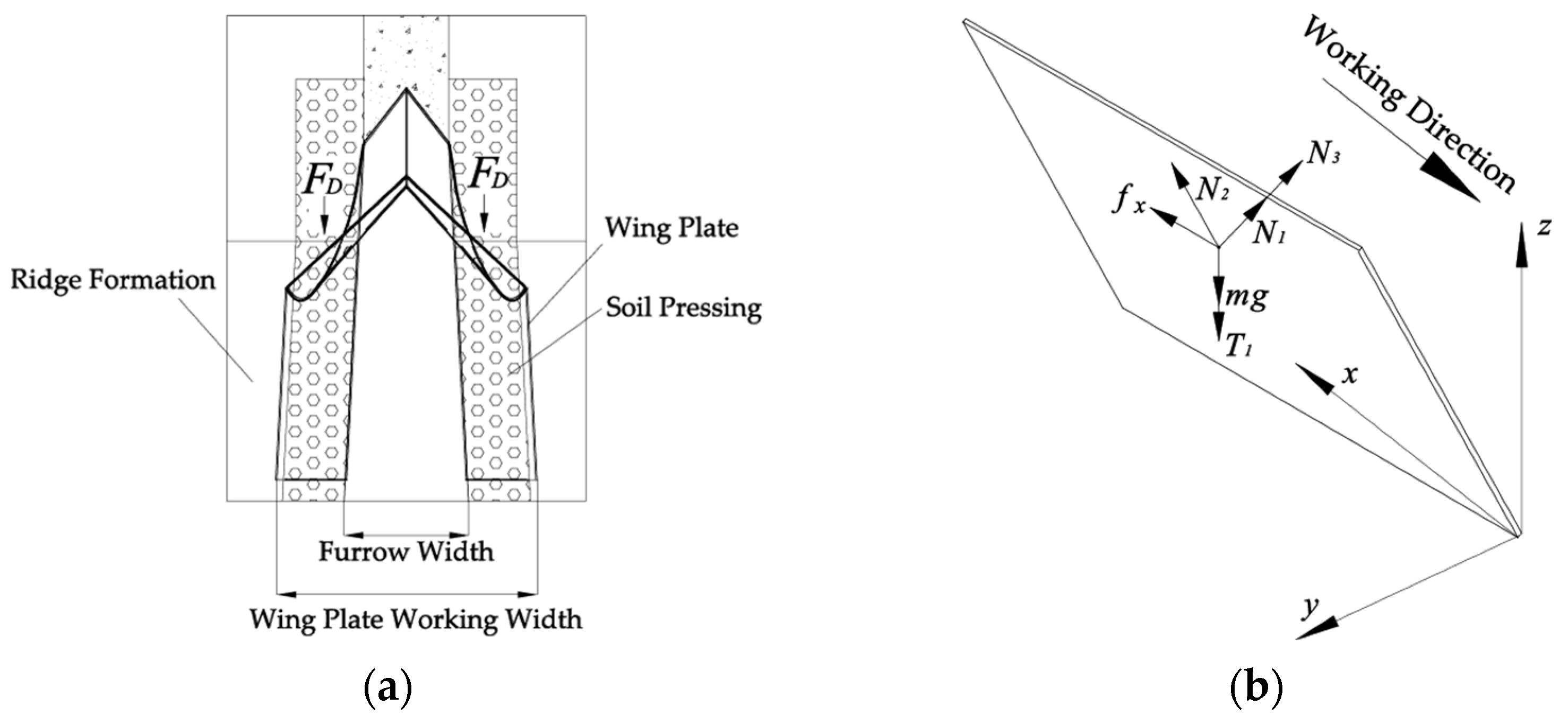
2.4.5. Force Analysis of Wing Plate

When the whole machine operates, the wing plate is narrow in front and wide at the back, so that it can form a ridge body by pressing both sides of the ridge with the forward motion of the implement, preventing the soil from falling back and forming a complete furrow as shown in Figure 11a. The resistance of the wing plate is mainly generated by the interaction and friction between the wing plate and the soil. The traction resistance F2 of the wing plate is:
F 2 = f x + F D
After the furrowing surface to form the ridge, the wing plate is pressed on the side wall of the ridge and furrow, currently, the wing plate is subjected to the soil extrusion counterforce FD, which is symmetrically distributed on the opposing wing plate, and the opposite of the forward direction.
Meanwhile, the wing plates are also subjected to the friction force fx of the soil, which is symmetrically distributed on the opposing wing plates as shown Figure 11b. The plowshare furrowing and ridging device carries part of the gravity of the sweet potato ridging and shaping machine in addition to its own gravity during field working. The support force of the soil on the wing plate includes the support force of the ground on the wing plate, and the support force of the side of the ridges and the soil extrusion counterforce FD on the wing plate. Since the gravity of the wing plate mainly acts on the side of the ridges, the support force of the ground on the wing plate is ignored in the process of calculating the friction force. As shown in Figure 11b, the friction force fx can be expressed as:
f x = μ m g + T 1 sin ϕ + N 3
where μ is coefficient of friction between wing plate and soil; m is mass of wing plate; T1 is pressure of the whole machine on the wing plate; ϕ is ridge inclination; N3 is the support force of the wing plate by the soil extrusion counterforce FD.
In summary, the total resistance of wing plate on forward direction is:
F 2 = 2 μ m g + T 1 sin θ + N 3
The traction resistance of the furrowing device consists of two parts: the resistance of the furrowing surface and the resistance of the wing plate. Among them, the wing plate parameter is basically an invariable parameter, which is only related to the pressure and soil properties. The surface parameters of the furrowing and ridging device and the motion parameters of the soil on the surface are the basis for the design of the surface, of which the variable geometric parameters are the installation angle ε1, the push angle γ1, and the element-line angle difference θ.
For comprehensive consideration, under the condition of guaranteeing the performance quality and minimizing the traction resistance, the installation angle of 27.5°, the bulldozing angle of 38°, and the element-line angle difference of 10.5° were selected.
The force analysis of the furrowing and ridging device is only used as a parameter solving process. In the actual field operation, the distribution of the devices touching the soil of the machine is uneven, and the soil resistance is complicated and difficult to predict. And the design of the whole machine should not only consider the situation of a single device, should be comprehensive analysis of the whole machine, so in the field operation, the average fuel consumption to analyze the traction resistance of the whole machine.

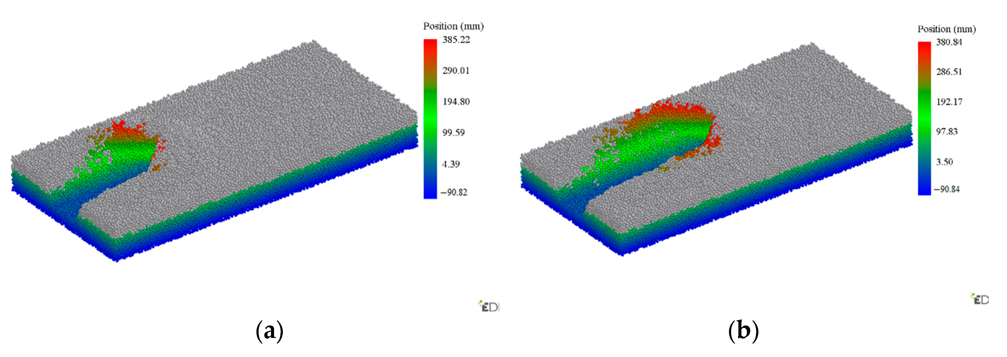
2.5. Analysis of Soil Particle Motion Based on EDEM

2.5.1. Simulation Model Building of EDEM

Based on the determined parameters, Inventor software was used to establish a simulation model of the plowshare furrowing and ridging device, and the model was converted to STEP format and imported into the EDEM software. To improve the calculation speed and operational efficiency of EDEM software, the parts that do not produce contact with the soil are omitted to simplify the model. The material of the plowshare furrowing and starting device was set to 65 Mn steel plate in combination with the actual processing situation to simulate as accurately as possible the machine-soil interaction during field working.
Soil particle modeling is the key to determining the simulation test results, and to be close to the soil characteristics in the field, the soil parameters were determined with reference to relevant literature [26,27,28], the EDEM material library and relevant experiments. To better explore the soil particle motion law, the soil particles are set to be regular and the same shape, and the spherical particles with a radius of 6 mm are used to form a single soil particle. The motion model between soil particles is selected as JKR model. The basic simulation parameters are shown in Table 1.
To avoid the influence of the boundary of the simulation soil tank on the simulation experiment, a simulation soil tank of length (4000 mm) × width (1500 mm) × height (400 mm) was established, and the height of the soil was 300 mm. As shown in Figure 12a, in order to observe the motion law of soil particles, the soil in the soil tank was divided into two soil layers, namely, Plough layer (0–150 mm) and Plow sole (150–300 mm), and the soil particles were generated by two particle factories with the same soil particle parameters.
To study the soil motion pattern, the device was simulated based on the parameters of forward speed of 0.8 m/s and embedded depth of 200 mm.The simulation model of plowshare furrowing and ridging device is shown as Figure 12b.

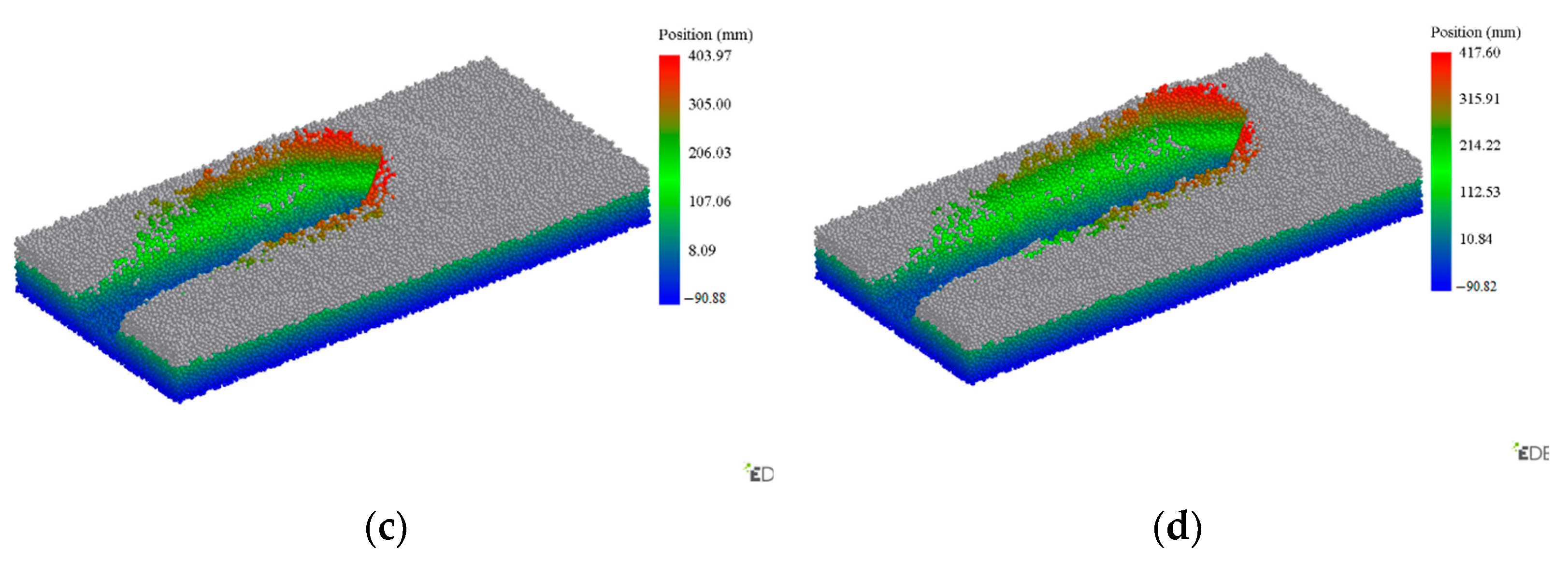
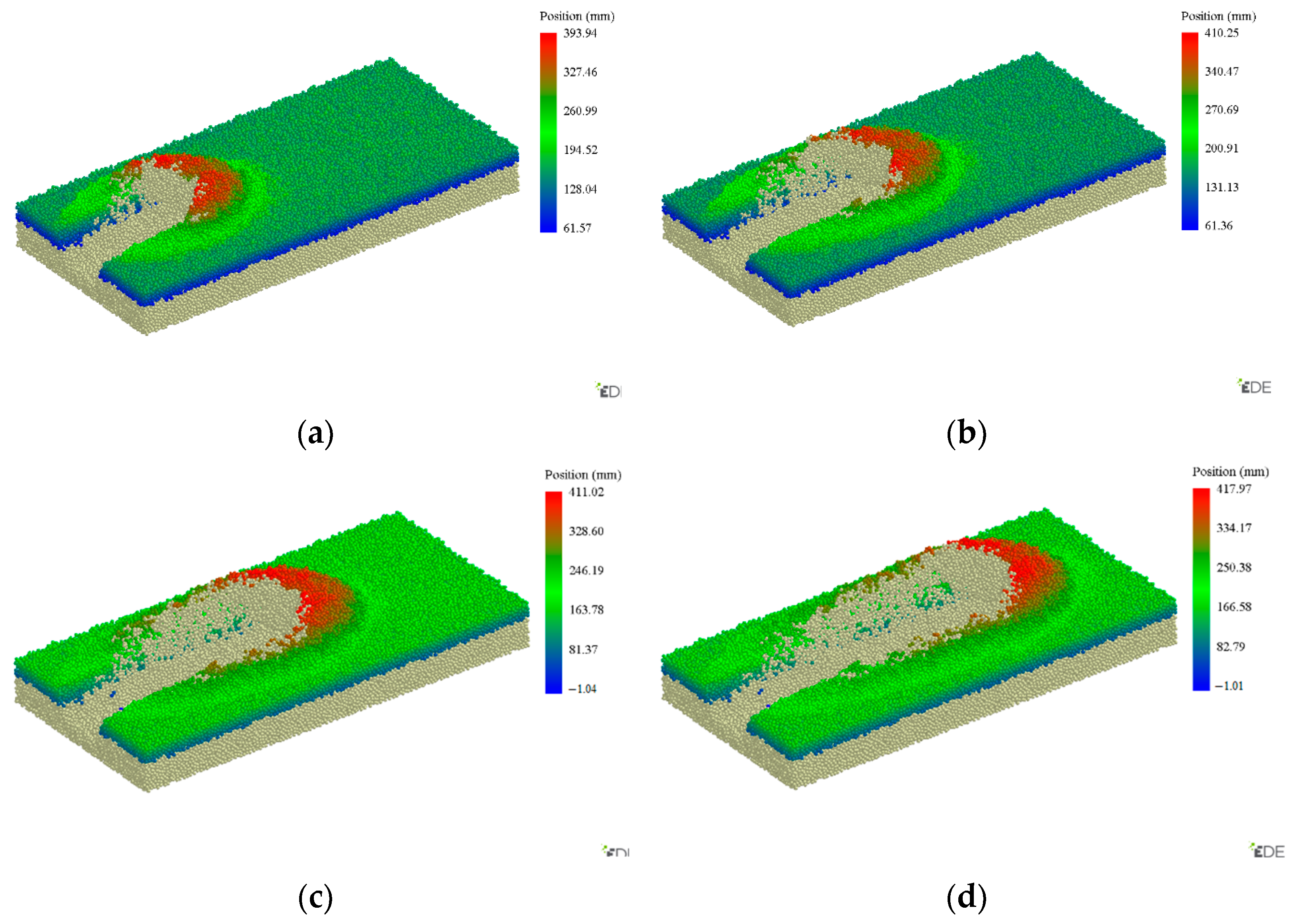
2.5.2. Analysis of Soil Motion Pattern in Plow Sole

Plowshare furrowing and ridging device contacted and interacted with the soil at 5.5 s and stabilized the work at 8.5 s. To explore the effect of the plowshare furrowing and ridging device on the soil motion pattern of the plow sole, the soil motion was analyzed at different working stages. In the post-processing module of EDEM software, the soil in plow sole was stained according to the position data of soil particles on the Z-axis, and according to the size of the value, the soil was stained with three colors of red, green, and blue in descending order, and the gradient color was selected to connect smoothly between each color. To better explore the soil motion pattern, in the post-processing module of EDEM software, the model of the ploughshare furrowing and ridging device was chosen not to display, but only the soil particle model.
As can be seen from Figure 13b, the displacement pattern of most of the soil is more consistent, but the soil particles close to the side wall of the ridge body are more different. Figure 13c,d of the soil in the plowshare furrowing and ridging device in the forward process, by the furrowing surface on the inside of the soil extrusion fall out of the surface, after reaching the highest point back to the top of the ridge and the side wall of the ridge body, in the extrusion of the wing plate continues to occur under the effect of a small displacement and ultimately stabilized in the Ridge side.
Analysis of soil motion pattern, the larger depth of furrowing and lower forward speed makes it harder for the bottom layer of soil to move to the Ridge surface, when moving on the surface of the furrowing plough body, by the extrusion of the soil in the tillage layer and the effect of gravity, the soil’s trajectory in furrowing surface is usually leaning down. Therefore, the soil in plow sole is mostly in the Ridge side.

2.5.3. Analysis of Soil Motion Pattern in Plough Layer

From Figure 14b, the soil moved from the upper part of the furrow to the height above the ground, and then fell back to the middle of the ridge surface. The motion trajectory of most of the soil particles is relatively consistent. The soil in Figure 14c,d in forward process of plowshare furrowing and ridging device, interacts with soil of plow sole on furrowing surface, by the soil of plow sole lifting and extrusion, motion to the middle of the ridge surface.
During the whole forward process, there is basically no contact between the plough layer soil and furrowing surface. The soil of plow sole uses its own volume to lift the soil of the plough layer upward throughout the process, so that the soil of the plow layer can be moved to the middle position of the ridge surface at a low forward speed.

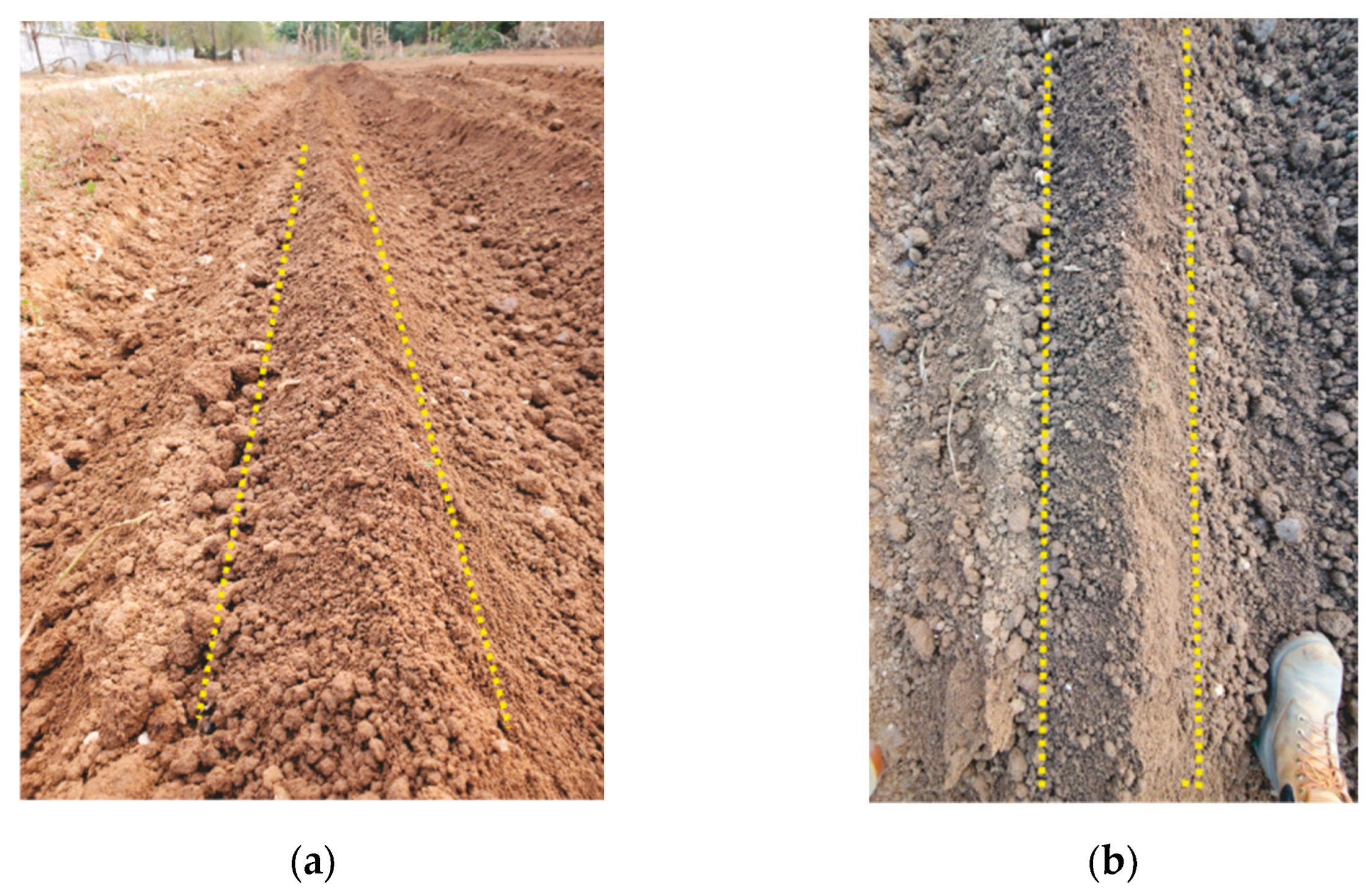
2.5.4. Verification Test of Plowshare Furrowing and Ridging Device
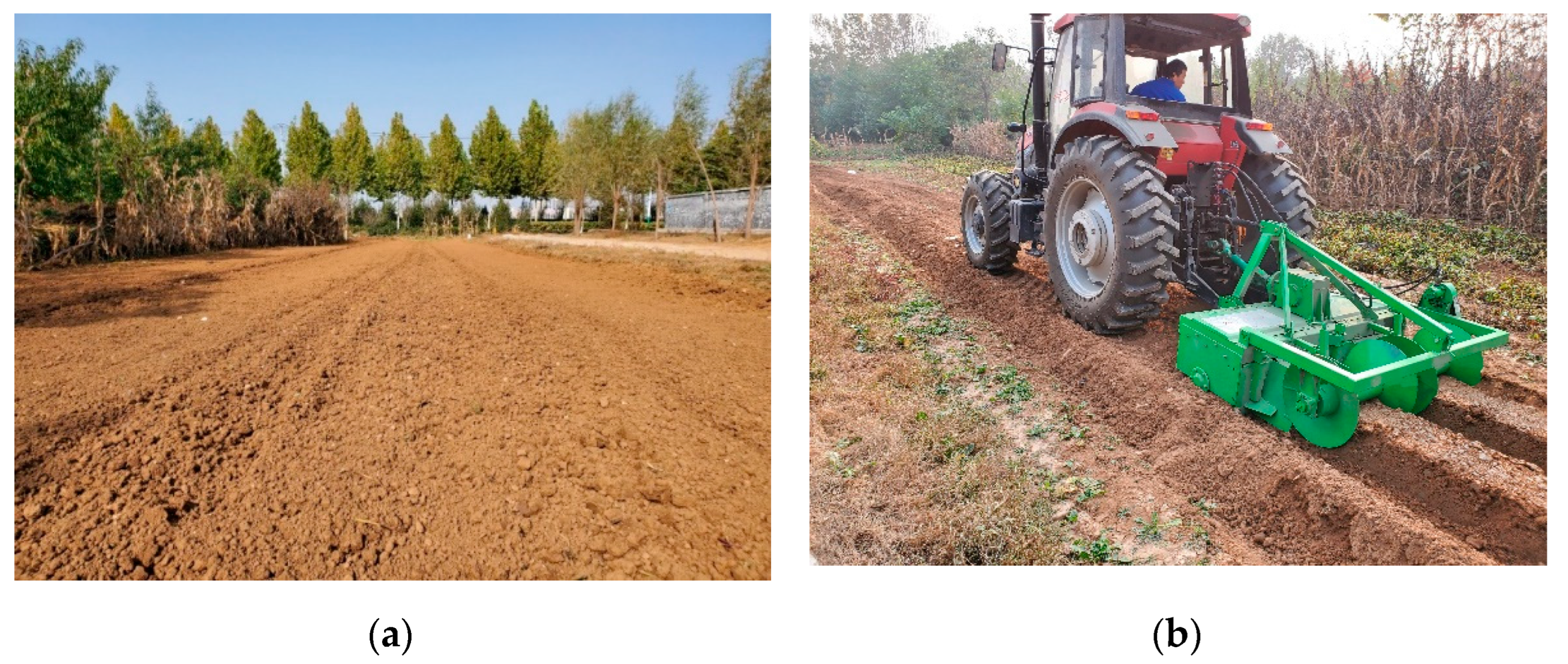
To explore the real operating effect of the plowshare type furrowing and shaping device, a separate verification test was carried out on it. The machine used in the test was a sweet potato ridging and shaping machine with the pressing and shaping device removed. The test used plowshare type furrowing device shown in Figure 15. During the test, the device was attached to the frame by sleeve fastening.
During the test, the embedded depth of plowshare furrowing and ridging device was controlled at 200 mm, and the average forward speed of the machine was maintained at 0.8 m/s, to compare the performance of the field test and the EDEM simulation test.
The field operation effect is shown in Figure 16, and the middle of the two yellow lines is the soil throwing effects. The actual working performance of the plowshare furrowing and ridging device is generally consistent with the performance of the simulation test.

2.6. Field Test

To analyze the field performance, field tests and simulation verification tests of sweet potato ridging and shaping machine were carried out in the experimental field; the whole machine and each device were processed according to the given parameter structure. comparing with EDEM simulation test, field verification test was carried out for the plowshare furrowing and ridging device.
To verify the effect of sweet potato ridging and shaping machine on field operation, the effect of soil penetration depth, forward speed of the whole machine, soil water content on the operation quality and fuel consumption was tested to obtain better working parameters.

2.6.1. Test Condition

The length of the experimental field was 50 m, and the width was 20 m. One week before the test, the soil of the test field was stubbled and leveled, as shown in Figure 17a. According to the agronomic requirements of sweet potato cultivation, the experimental field was simulated as a real field state.
The test tractor is a LX954 four-wheel-drive tractor, and the wheelbase of the test equipment has been adjusted according to the agronomic requirements, and the parameters of the tractor are shown in Table 2, the field test procedure is shown in Figure 17b. The SL-TSC digital multifunctional soil property tester can simultaneously measure the soil moisture content, temperature, and soil compactness, as shown in Figure 18a. Leno WR-Y2-50-L fuel consumption tester with supporting equipment and computer to measure tractor fuel consumption, as shown in Figure 18b. Tape measure, steel ruler, marker, etc.

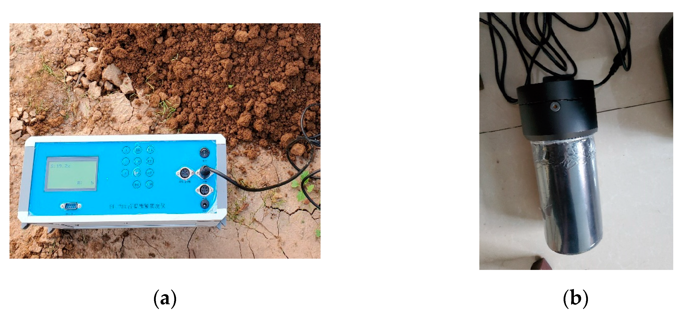
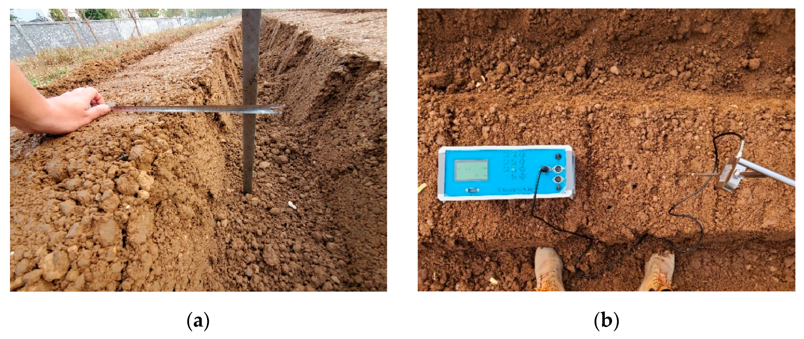
2.6.2. Evaluation Indicators and Test Methods

The forward speed of the machine is controlled by the tractor, and the speed of the suppression shaping roller and rotary tillage knife are adjusted before the operation, which are 100 r/min and 330 r/min, respectively. 20 m of adjustment length is reserved after embed soil to facilitate the stabilization of the working condition of the sweet potato ridging and shaping machine, and to achieve the test set values of each parameter. The length of each test was set at 30 m, and markers and blank areas were set on both sides of the test area.
Referring to JB/T 7864-2013 Test Methods for Dry Field Middle Tillage Fertilizer Pursuing Machines [29] and NY/T740-2003 Operation Quality of Field Furrowing Machines for evaluation [30], according to the actual working situation, the stability coefficient of the ridge height and the average soil compactness will be taken as the evaluation indicators of the operation situation, and the average fuel consumption of the tractor will be taken as the evaluation indicators of the machine situation.
Stability coefficient of the ridge height (Y1): Select 10 measurement points on each test ridge at equal intervals along the tractor’s forward direction, with an interval of 2 m between adjacent measurement points. Place a tape measure on the top of the ridge, fit the ridge surface, and at the same time in the center of the furrow to place a steel ruler, the intersection of the two rulers is the measurement point of the height of the ridge, take the average value of the 10 measurement points for each test of ridge height. Measurement is shown in Figure 19a. The stability coefficient of ridge height can be expressed as:
T = 1 S b 1 n i = 1 n h i × 100 %
where T is stability coefficient of ridge height; Sb is standard deviation of ridge height, m; hi is ridge height at the i-th measurement point, m; n is number of measurement points, n = 10.
Average soil compactness: To measure the average soil tightness, the multifunctional soil property tester was used to test the ridge surface after ridging and forming, and the depth of measurement was 0.1 m, respectively, and the center of the ridge surface was selected as the test point, with an interval of 2 m, and the average value of 10 measurement points was taken as the average soil compactness. Measurement is shown in Figure 19b.
Average fuel consumption: Fuel consumption tester and supporting equipment were used to record the fuel consumption data of the tractor throughout each test, and the average fuel consumption of the tractor was taken after the tractor was stabilized [31].

2.6.3. Test Scheme

In the ridging work in field, the tractor is in a low-speed and heavy-duty state, its speed range is generally in the range of 0.6~1.0 m/s, the test takes the speed range of 0.6~1.0 m/s. The minimum Embedded depth of the furrowing and ridging device is 192 mm, the smaller Embedded depth will lead to the soil volume of the ridge is not enough, cannot form a ridge; the larger will increase the traction resistance of the machines significantly. Comprehensive consideration, the soil depth is set to 200–220 mm. Soil moisture also has a significant impact on the effect of ridging [8], smaller soil moisture content will lead to a reduction in the cohesion between soil particles, comprehensive consideration, soil moisture is controlled at 16%–20%.
Conducting tests on the effects of embedded depth (B), forward speed (A) of the sweet potato ridging and shaping machine and soil moisture (C) on stability coefficient ridge height (Y1). Combined with the Design-Expert software, the Box-Behnken response surface method was used for the test design, and the levels of the test factors are shown in Table 3.

3. Results and Discussions

3.1. Test Results

The results of the test are shown in Table 4.

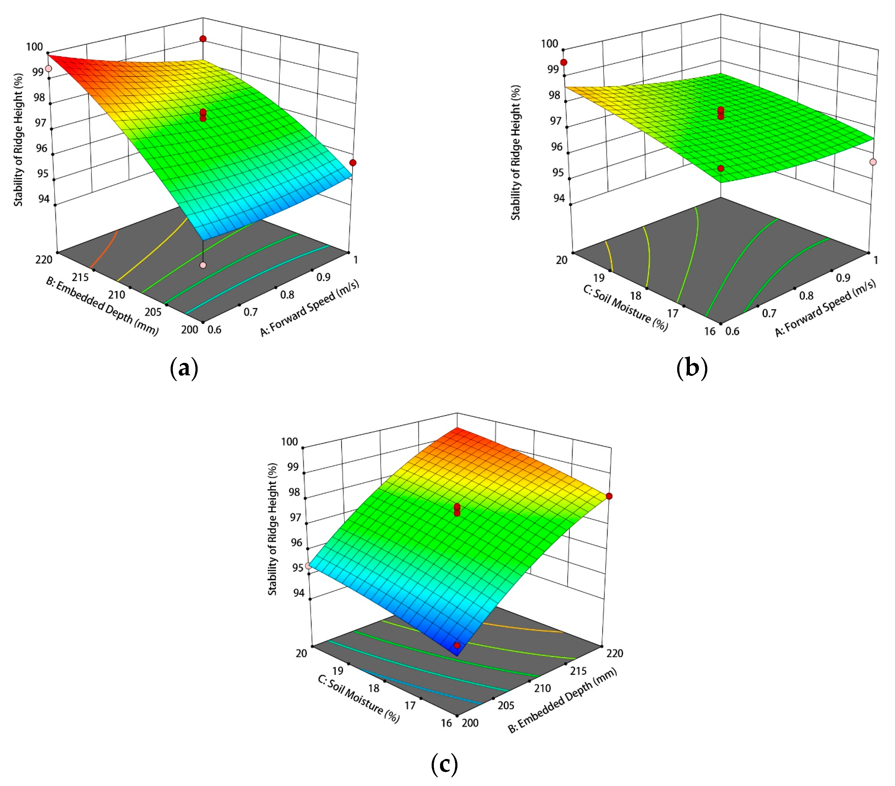
3.2. Analysis of Test Results

Analysis of Stability Coefficient of Ridge Height

According to the test results in Table 5, the Analysis function module of Design-Expert software is used to analyze the test results. The quadratic multivariate regression fitting of ridge high stability was carried out, and the regression equation of ridge high stability on each independent variable was obtained as follows:
Y1 = 97.422 − 0.39125A + 1.96625B + 0.6C − 0.4675AB − 0.16AC + 0.03BC + 0.17775A2 − 0.49725B2 − 0.13475C2
where A is forward speed; B is embedded depth; C is soil moisture.
Figure 20a show that the embedded depth (B) has a significant effect on the stability of ridge, and Figure 20c show that the soil moisture (C) also influences the stability of ridge, and Figure 20a,b also show that forward speed (A) only has a tiny effect.
It can be seen from the design principle of the plowshare furrowing and ridging device that the soil volume transported to the top part of the ridge increases with the increase of the embedded depth (B), and the ridge height after being crushed and shaped is larger and has higher stability coefficient of the ridge height (Y1). The increase of soil moisture (C) makes the ridge more stable and less prone to collapse after the pressing and forming operation, and the stability coefficient of the ridge height (Y1) is also increased.

3.3. Paramater Pptimization and Comparative Test

According to the results of BBD, the Numerical function in the Optimization module of Design-Expert software was used to optimize the working parameters of the sweet potato ridging and shaping machine. Among them, the greater the stability coefficient of the ridge height, the more the ridge height meets the agronomic requirements.
In summary, the regression models Y1 was optimized by taking the maximum stability coefficient of ridge height (Y1) as the solution objectives. The better work parameters of the sweet potato ridging and shaping machine was found to be 196 mm for embedded depth (B), 0.82 m/s for forward speed (A), and 18% for soil moisture (C). Currently, the stability coefficient of ridge height (Y1) is 99.84%.
To verify the performance of the designed sweet potato ridging and shaping machine, it was tested in comparison with 1GQL-2 sweet potato two rows rotary plowing and ridging machine [17]. the embedded depth was set at 200 mm, the forward speed of the machine was set at 0.8 m/s; and the soil moisture in the test field was set close to 18%. The results of the test are shown in Table 6.
As can be seen from Table 6, compared with 1GQL-2, the sweet potato ridging and shaping machine has improved the stability of the ridge height by 2.1%, and the soil tightness increased by 62 kPa, which improved the overall stability of the ridge. Thus, sweet potato ridging and shaping machine can meet the agronomic requirements of sweet potato and provide better conditions for sweet potato transplanting. Meanwhile, under the same test conditions, the sweet potato ridging and shaping machine reduced the average fuel consumption by about 4.2% compared with 1GQL-2, which has a good energy saving effect and fuel economy.

4. Discussion

Under the same conditions, the sweet potato ridging and shaping machine adopts a plowshare furrowing and ridging device with better soil guiding performance, and the soil volume transported to the ground is larger, resulting in a higher ridge height than 1GQL-2. Meanwhile, the sweet potato ridging and shaping machine adopts active pressing roller to shape the ridge body, and the average soil compactness is better. 1GQL-2 uses a passive pressing roller and is placed on the ridge body instead of fixed on the frame, so the pressing and shaping effect on the ridge is poor. Compared with the ridging device of 1GQL-2, the furrowing and ridging device of the sweet potato ridging and shaping machine has been optimized, but the traction resistance of the active pressing roller is slightly greater than the roller of 1GQL-2. Through several tests, the average fuel consumption of sweet potato ridging and shaping machine is slightly reduced compared with 1GQL-2.
The sweet potato ridging machine designed in this paper can complete the ridging and shaping operation at one time, meet height of sweet potato agronomic requirement, greatly improve the average soil compactness, enhance the stability of ridge body, and meet the planting conditions of artificial and mechanical transplanting. The average soil compactness measured in the field experiment was within the appropriate range, which was conducive to the formation and expansion of sweet potato root and the increase of sweet potato yield [32,33].
There are still some limitations in this study. The sweet potato ridging and shaping machine designed is only suitable for field planting areas such as Henan, Jiangsu and Shandong, and the application in hilly areas is not considered. At present, the planting areas in Chongqing, Hubei, Hainan, and other places are mostly hilly, and the sweet potato industry is still more dependent on manual labor. In the following research, we can refer to the structure of this machine to further optimize the cooperation relationship between the devices and design a sweet potato ridging and shaping machine that meets the agronomic requirements in hilly areas.
Meanwhile, the sweet potato transplanting device can also be studied and added based on this machine, and the key device in this study can be split and combined with the existing sweet potato transplanting mechanism to form a combined sweet potato transplanting machine, which can complete the tillage and planting operations at one time. Save labor costs, improve the overall economic benefits.

5. Conclusions

  • Aiming at the problems of existing ridging and shaping machine such as poor ridging effect, a sweet potato ridging and shaping machine was designed, and its working principle was introduced. The main design parameters of rotary device and pressing and forming device was determined. The force model of ploughshare furrowing and ridging device was established, and the design parameters of each part of ploughshare furrowing and ridging device were determined. EDEM software was used to analyze the soil motion pattern during the operation of ploughshare furrowing and ridging device and carried out field verification test.
  • A field test was conducted on a sweet potato ridging and shaping machine using the Box-Behnken response surface methods, and the results showed that the performance was better at embedded depth of 196 mm, a forward speed of 0.82 m/s for the machine, and a soil moisture of 18%.
  • Comparative tests show that the performance and fuel consumption of the sweet potato ridging and shaping machine are better than that of 1GQL-2 Sweet potato two rows rotary plowing and ridging machine. It can meet the agronomic requirements of the main sweet potato producing areas in China and provide the basis for the subsequent research of sweet potato combined transplanter and ridging machinery in hilly areas.

Author Contributions

Conceptualization, X.C. and M.C.; methodology, M.C.; software, X.C.; validation, X.C. and M.L.; formal analysis, Y.L.; investigation, H.W.; resources, D.Y.; data curation, M.L.; writing—original draft preparation, X.C.; writing—review and editing, M.C.; visualization, Y.L.; supervision, H.W.; project administration, H.W.; funding acquisition, D.Y. All authors have read and agreed to the published version of the manuscript.

Funding

This research was funded by the Special Program for Scientists in China Agriculture Research System (grant number: CARS-09-P25).

Institutional Review Board Statement

Not applicable.

Data Availability Statement

All data are presented in this article in the form of figures and tables.

Acknowledgments

The authors would like to acknowledge the College of Mechanical and Electrical Engineering at Qingdao Agricultural University and Special Program for Scientists in China Agriculture Research System.

Conflicts of Interest

The authors declare no conflict of interest.

References

  1. Ma, B.; Hu, L.; Xu, L.; Tian, L.; Ji, F.; Wang, B. Status about sweet potato planting and its production machinery in China. J. Chin. Agric. Mech. 2013, 34, 42–46. [Google Scholar]
  2. Hu, J.; Zhang, W.; Yan, W. Research status and prospect of sweet potato ridging machines at home and abroad. J. Chin. Agric. Mech. 2018, 11, 12–16. [Google Scholar] [CrossRef]
  3. Li, L.; Xu, Y.; Pan, Z.; Zhang, H.; Sun, T.; Zhai, Y. Design and Experiment of Sweet Potato Up-Film Transplanting Device with a Boat-Bottom Posture. Agriculture 2022, 12, 1716. [Google Scholar] [CrossRef]
  4. Dai, F.; Zhao, W.; Zhang, F.; Ma, H.; Xin, S.; Ma, M. Research Progress Analysis of Furrow Sowing with Whole Plastic-film Mulching on Double Ridges Technology and Machine in Northwest Rainfed Area. Trans. Chin. Soc. Agric. Mach. 2019, 50, 1–16. [Google Scholar] [CrossRef]
  5. Dai, F.; Zhao, W.; Shi, R.; Zhang, F.; Ma, H.; Ma, M. Design and Experiment of Operation Machine for Filming and Girdle Covering on Double Ridges. Trans. Chin. Soc. Agric. Mach. 2019, 50, 130–139. [Google Scholar] [CrossRef]
  6. Dai, F.; Zhang, S.; Song, X.; Zhao, W.; Ma, H. Design and Test of Combined Operation Machine for Double Width Filming and Covering Soil on Double Ridges. Trans. Chin. Soc. Agric. Mach. 2020, 51, 108–117. [Google Scholar] [CrossRef]
  7. Lin, J.; Zhang, T.; Chen, T. Design and test of subsoiling rotary tilling and tilling combined operating machine. Trans. Chin. Soc. Agric. Mach. 2019, 50, 28–39. [Google Scholar] [CrossRef]
  8. Bao, P.; Wu, M.; Guan, C. Design of plow-rotary style ditching and ridging device for rapeseed seeding. Trans. Chin. Soc. Agric. Mach. 2017, 33, 23–31. [Google Scholar] [CrossRef]
  9. Wang, F.; Yang, L.; Bao, Y.; Jiang, J. Development of air-suction ridging and seeding machine for carrot. Trans. Chin. Soc. Agric. Mach. 2020, 36, 35–45. [Google Scholar] [CrossRef]
  10. Fu, Q.; Jian., S.; Jia, H.; Zhao, W.; Lu, A.; Wei, G. Design and experiment on maize stubble cleaning fertilization ridging seeder. Trans. Chin. Soc. Agric. Mach. 2016, 32, 9–16. [Google Scholar] [CrossRef]
  11. Li, S.; Pan, J.; Zhong, J.; Li, W.; Yang, D.; Mo, Q. Design and Evaluation of a Machine Integrating Ridge-Breaking, Fertilizing, and Ridging for Ratoon Sugarcane Without Intertillage. Sugar Tech 2022, 24, 1913–1923. [Google Scholar] [CrossRef]
  12. Zhang, Q.; Liao, Y.; Tao, W.; Liao, Q. Design and experiment for ridge lifting device of rapeseed planter. J. Gansu Agric. Univ. 2020, 55, 181–189. [Google Scholar] [CrossRef]
  13. Liu, X.; Xiao, W.; Ma, L.; Liu, L.; Wan, G.; Liao, Q. Design and Ditching Quality Experiment on Combined Ship Type Opener of Direct Rapeseed Seeder. Trans. Chin. Soc. Agric. Mach. 2017, 48, 79–87. [Google Scholar] [CrossRef]
  14. Bu, X.; Liao, Q.; Sun, W.; Wei, G.; Zhang, Q.; Wang, P. Design and test of a boot-like acute angle furrow plough for preparing ditch of rapeseed seedbed. J. Huazhong Agric. Univ. 2021, 40, 77–84. [Google Scholar] [CrossRef]
  15. Ridge Forming Machine with Soil Miller-Aur. Available online: https://weremczukagro.com/en/products/ridge-forming-machine-aur/?from=1144 (accessed on 12 August 2023).
  16. Reverse Tiller: G35. Available online: https://www.vedafarming.com/farm-implement/reverse-tiller-small (accessed on 12 August 2023).
  17. Wang, B.; Hu, L.; Wang, S. Design and experiment of sweet potato transplanting operation machine with rotary tillage, ridging, and covering film functions. J. China Agric. Univ. 2018, 23, 116–125. [Google Scholar] [CrossRef]
  18. Liu, X.; Jiang, L.; Deng, J.; Zheng, T. Development of 1KQ-30 sweet potato ridging machine. Sichuan Agric. Agric. Mach. 2011, 38–39, 41. [Google Scholar] [CrossRef]
  19. DB37/T 2157-2012; Technical Regulations for Fresh Sweet Potato Production. Shandong Academy of Agricultural Sciences: Shandong, China, 2012.
  20. DB37/T 3611-2019; Technical Regulations for Sweet Potato Production. Shandong Agricultural University: Shandong, China, 2019.
  21. GB/T 5669-2017; Rotary Tillage Machinery Blades and Holders. China National GB Standard Research: Nanjing, China, 2017.
  22. Zhang, C.; Huang, M.; Zhang, S. Design and test of the pressing parts of the vegetable finishing Machine. J. Chin. Agric. Mech. 2023, 44, 49. [Google Scholar] [CrossRef]
  23. Wei, G.; Zhang, Q.; Liu, L.; Xiao, W.; Sun, W.; Liao, Q. Design and Experiment of Plowing and Rotary Tillage Buckle Device for Rapeseed Direct Seeder. Trans. Chin. Soc. Agric. Mach. 2020, 51, 38–46. [Google Scholar] [CrossRef]
  24. Chinese Academy of Agricultural Mechanization Sciences. Handbook of Agricultural Machinery Design; Machinery Industry Press: Beijing, China, 2007; pp. 175–220. [Google Scholar]
  25. Lei, Z. Research on the Impact of High-Speed Plough Structure and Working Parameters on Tillage Resistance; Shihezi University: Shihezi, China, 2020. [Google Scholar] [CrossRef]
  26. Lu, J.; Liu, Q.; LI, Z. Design and experiment of soil cultivating device of plowshare potato field cultivator. Trans. Chin. Soc. Agric. Mach. 2021, 52, 71–82. [Google Scholar] [CrossRef]
  27. Lu, J.; Liu, Q.; Yang, D. Design and test of key components of ploughshare potato field cultivator in sandy loam. Trans. Chin. Soc. Agric. Mach. 2021, 52, 27–39. [Google Scholar] [CrossRef]
  28. Shi, Y.; Chen, X.; Chen, M.; Wang, D.; Shang, S. Design and Experiment on Ploughshare Furrowing Ridging Device of Sweet Potato Ridging Shaping Machine. Trans. Chin. Soc. Agric. Mach. 2022, 53, 16–25. [Google Scholar] [CrossRef]
  29. JB/T 7864-2013; Middle Tillage Fertilizer Pursuing Machines. China Agricultural Machinery Research Institute: Beijing, China, 2013.
  30. JB/T 7864-2013; Field Operation Quality of Ditchers. Nanjing Institute of Agricultural Mechanization, Ministry of Agriculture and Rural Affairs: Nanjing, China, 2003.
  31. Çıtıl, E.; Taner, A.; Çarman, K. Artificial Neural Network Model for Predicting Specific Draft Force and Fuel Consumption Requirement of a Mouldboard Plough. Selcuk J. Agric. Food Sci. 2019, 33, 241–247. [Google Scholar] [CrossRef]
  32. Shi, W.; Zhang, B.; Liu, H.; Zhao, Q.; Shi, C.; Wang, X.; Si, C. Response mechanism of sweet potato storage root formation and bulking to soil compactness and its relationship with yield. Acta Agron. Sin. 2019, 45, 755. [Google Scholar] [CrossRef]
  33. Liu, Y.; Si, C.; Liu, H.; Meng, D.; Shi, C. Effects of Soil Compactness on Population Structure and Yield of Sweet Potato. Shandong Agric. Sci. 2019, 10, 99–103. [Google Scholar] [CrossRef]
Figure 1. Structure diagram of sweet potato ridging and shaping machine: 1 Plowshare furrowing and ridging device; 2 Front plow; 3 Rotary tillage device; 4 Pressing and shaping device; 5 Frame.
Agriculture 13 01641 g001
Figure 2. (a) The Rotary tillage device structure. (b) Schematic diagram of blades arrangement of Rotary tiller device.
Agriculture 13 01641 g002
Figure 4. Structure diagram of Plowshare furrowing and ridging device: 1 Connection frame; 2 Furrowing surface; 3 Wing plate.
Agriculture 13 01641 g004
Figure 5. Ridge cross section of sweet potato planting agronomic requirement. w1 is top width; h is height of ridge; h2 is height of ridge hathpace; ϕ is ridge inclination; h1 is height of furrow; w0 is the furrow width; W is the spacing between ridges.
Agriculture 13 01641 g005
Figure 6. Schematic diagram of Guiding curve. L1 is openness of CB; lAB is straight-line length of the beginning; ε is installation angle; H1 is height of section BC; H2 is height of section CD.
Agriculture 13 01641 g006
Figure 7. (a) Principle of Surface Formation (b) Variation rule of Element line angle. θmin is minimum value of the Element line angle, °; θmax is maximum value of the Element line angle, °θ0 is initial value of the Element line angle, °; Z is height of guiding curve.
Agriculture 13 01641 g007
Figure 8. Schematic diagram of wing plate. ω is an angle of tilt; D1 is the length of the front part; D2 is the length of the rear part; P1 is the width of the front part; P2 is the length of the front part.
Agriculture 13 01641 g008
Figure 9. Schematic diagram of speed triangle. V is the forward velocity; λ is the angle between V and VYZ; β is the angle of VXY with the X-axis; α is the angle of VYZ with the Y-axis; V is the lateral partial velocity.
Agriculture 13 01641 g009
Figure 10. Force analysis of furrowing surface. FC is the cutting force of the surface on the soil; FP: is the total pressure of the soil; Ff is the frictional resistance between the soil and surface; Fv is the force driving the soil motion.
Agriculture 13 01641 g010
Figure 11. Force analysis of Wing plate. (a) Force analysis of soil extrusion counterforce FD. (b) Force analysis of friction force fx.
Agriculture 13 01641 g011
Figure 12. (a) Soil tank model. (b) Simulation model.
Agriculture 13 01641 g012
Figure 13. Soil motion pattern of Plow sole. (a) Time = 6 s. (b) Time = 9 s. (c) Time = 10 s. (d) Time = 11.5 s.
Agriculture 13 01641 g013aAgriculture 13 01641 g013b
Figure 14. Soil motion pattern of Plough layer. (a) Time = 6 s. (b) Time = 9 s. (c) Time = 10 s. (d) Time = 11.5 s.
Agriculture 13 01641 g014
Figure 15. Plowshare furrowing and ridging device.
Agriculture 13 01641 g015
Figure 16. Working effects of plowshare furrowing and ridging device. (a) Full view of working effects. (b) soil throwing effects.
Agriculture 13 01641 g016
Figure 17. (a) Experimental field status. (b) Field test procedure.
Agriculture 13 01641 g017
Figure 18. (a) Multifunctional Soil property tester. (b) Fuel consumption tester.
Agriculture 13 01641 g018
Figure 19. (a) Measurement process of ridge height. (b) Measurement process of soil compactness.
Agriculture 13 01641 g019
Figure 20. Stability coefficient of ridge height interaction factor response surface analysis (ac).
Agriculture 13 01641 g020
Table 1. Basic simulation Parameters of EDEM Models.
ParametersPlowshare Ditching and Ridge Device (Steel)Soil
Density/(kg∙m−3)78002600
Poisson’s ratio0.40.5
Modulus of shear/Pa7.0 × 10101 × 107
JKR surface energy coefficient (J∙m−2)-9.50
Soil-SteelSoil-Soil
Coefficient of static friction0.30.8
Coefficient of rolling friction0.050.3
Recovery Factor0.30.6
Table 2. Tractor working parameters.
ParametersValueUnit
ModelLX954-
Power≥70kW
Traction Force≥30kN
Maximum Torque380N∙m
Rated Fuel Consumption≤235g/kW∙h
Output Rotational speed540/720r/min
Table 3. Levels and codes of test variables.
LevelTest Factors
Forward Speed
A (m/s)
Embedded Depth
B (mm)
Soil Moisture
C (%)
−10.619016
00.820018
11.021020
Table 4. Design and results of the BBD.
TestTest FactorsEvaluation Indicators
NumberA
m/s
B
mm
C
%
Y1
%
10.62101697.59
21.02201899.11
30.82101897.19
40.82101897.48
50.82002095.37
60.82101897.75
70.62201899.41
80.62102099.54
90.62001894.16
100.82001694.66
110.82101897.66
120.82202098.98
130.82201698.15
141.02101695.71
150.82101897.03
161.02102097.02
171.02001895.73
Note: Y1 indicates significance of Stability coefficient of ridge height. The same as below.
Table 5. Analysis variance table of Stability coefficient of Ridge Height.
Source of VarianceStability Coefficient of Ridge Height Y1%
Sum of SquaresFreedomMean SquareF-Valuep-ValueSignificance
Model37.2594.145.730.0157*
A1.2211.221.700.2341
B30.93130.9342.820.0003**
C2.8812.883.990.0860*
AB0.874210.87421.210.3077
AC0.102410.10240.14180.7177
BC0.003610.00360.00500.9457
0.133010.13300.18420.6807
1.0411.041.440.2690
0.076510.07650.10580.7544
Residual5.0670.7223
Lack of Fit4.6831.5616.640.0101
Pure Error0.375140.0938
Total42.3116
Note: * indicates general significance, 0.05 < p < 0.1, ** indicates highly significant, p < 0.01.
Table 6. Comparative test results.
TypeTest Factors
Stability Coefficient of Ridge HeightAverage Soil
Compactness/kPa
Average Fuel Consumption
sweet potato ridging and shaping machine97.5327811,947
1GQL-2 sweet potato two rows rotary plowing and ridging machine95.4221612,474
Disclaimer/Publisher’s Note: The statements, opinions and data contained in all publications are solely those of the individual author(s) and contributor(s) and not of MDPI and/or the editor(s). MDPI and/or the editor(s) disclaim responsibility for any injury to people or property resulting from any ideas, methods, instructions or products referred to in the content.

