Article

Development and Experimental Validation of an Agricultural Robotic Platform with High Traction and Low Compaction

1
Bosch Engineering GmbH, Robert-Bosch-Allee 1, 74232 Abstatt, Germany
2
Institute of Agricultural Engineering, University of Hohenheim, Garbenstr. 9, 70599 Stuttgart, Germany
3
Department of Agricultural Engineering, Geisenheim University, Von-Lade-Str 1, 65366 Geisenheim, Germany
4
VARTA Microbattery GmbH, Varta-Platz 1, 73479 Ellwangen, Germany
5
University of Groningen, 9712 CP Groningen, The Netherlands
*
Author to whom correspondence should be addressed.
Agriculture 2023, 13(8), 1510; https://doi.org/10.3390/agriculture13081510
Submission received: 7 July 2023 / Revised: 18 July 2023 / Accepted: 26 July 2023 / Published: 28 July 2023
(This article belongs to the Special Issue Agricultural Machinery Design and Agricultural Engineering)

Abstract

:
Some researchers expect that future agriculture will be automated by swarms of small machines. However, small and light robots have some disadvantages. They have problems generating interaction forces high enough to modify the environment (lift a stone, cultivate the soil, or transport high loads). Additionally, they have limited range and terrain mobility. One option to change this paradigm is to use spikes instead of wheels, which enter the soil to create traction. This allows high interaction forces with the soil, and the process is not limited by the weight of the vehicle. We designed a prototype for mechanical soil cultivation and weeding in agricultural fields and evaluated its efficiency. A static and dynamic test was performed to compare the energy input of the electrical motor with precise measurements of the forces on the attached tool. The results indicate that the prototype can create interaction forces of up to 2082 N with a robot weight of 90 kg. A net traction ratio of 2.31 was reached. The dynamic performance experiment generated pull forces of up to 1335 N for a sustained net traction ratio of 1.48. The overall energy efficiency ratio for the machine reached values of up to 0.54 based on the created draft force and the measured input energy consumption.

1. Introduction

Sustainability is becoming an increasingly important factor in the development of future machinery. The political and social will is for agricultural production in Germany to significantly reduce CO2 emissions in the coming years. The actual goal of German policy is to reduce emissions by more than 30% by 2050 [1]. Typical methods for reducing CO2 in agriculture are electrification, the use of renewable energy, the reduced use of fertilizers, and the minimization of the impact of machinery. In addition, the energy required for a specific process can be optimized. However, while addressing the points above, issues such as the impacts on the ground (e.g., soil compaction) resulting from newly developed machines, such as agricultural robots and implements [2,3], should be properly evaluated.
Robots could help to improve energy efficiency for agriculture when we integrate sustainability into the engineering process. We could develop small and safe machines, which can work 24 h a day and are not fixed to day/nighttime to perform their work [4]. The realization of this vision is limited by how small and how sustainable the machines can get. The solution to this challenge depends on the task, the necessary interaction force, the working speed, and the operating range of the machines. Some authors suggest tractor-sized autonomous machines [5], and others suggest miniaturized robots (less than 100 kg), able to perform their tasks in swarms [6]. Some even suggest airborne robots [7], and others prefer ground vehicles [8,9]. In general, it is easier to realize autonomous machines in controlled infrastructure, like in a greenhouse, where the environment is known and the robot can have access to an unlimited power supply. Additionally, sensor perception performs better under controlled conditions [10]. However, autonomous machines are needed in big fields or environments too, where no energy infrastructure exists. Here, autonomous robots need to carry enough energy with them (fuel, batteries, etc.) to fulfill their tasks [8]. Specifically, electrically driven machines have the problem of range, as batteries currently have a low power density of up to 190 Wh/kg. This is many times less than conventional gasoline, with a power density of around 12,000 Wh/kg [11]. To make electrically powered machines commercially successful in agriculture, new energy storage technologies are needed, or the machines need to be more frugal and energy-efficient.
The weight of machines is known to influence soil properties and, thus, soil fertility [12]. When using conventional strategies to prepare the soil, maintain the crop, and harvest, machines need a specified interaction force, limiting the size and weight of the machines. When cultivating the soil, the machine must be strong enough to pull at least one soil preparation tool, like a hoe. The weight of wheeled vehicles is directly related to the possible pull force. Under perfect soil conditions, the net traction ratio (NTR) of tires reaches a maximum of 0.8 [13]. For ideal power transmission, the NTR should be around 0.4, accepting a wheel slip of 15–20% [14]. This implies that a tire should have at least 2.5 N of payload to create a draft force of 1 N. For loose and humid soil, this ratio becomes even smaller. Therefore, standard mobile agricultural machinery, like a tractor, should be at least 2.5 times heavier than the maximum expected draft force for tasks [14].
To avoid soil compaction and to decouple the direct weight from the draft force, early inventions used tools pulled by a cable. The first steam plows were used in 1880 in Germany, where two steam engines at the side of the field carried a tilting plow with a cable over the field [15]. Modern tractors rely on the traction coefficient of the tires to transfer the applied power to traction force. To minimize soil compaction, the machines use big tires or tracks. Additionally, some farmers use controlled traffic farming to minimize the compacted area in the field. Therefore, the same paths are always used by the machines, leaving the area beside the tracks untouched. Some modern tractors use active air pressure variation in the tires to minimize soil compaction.
One method to increase traction is to use spikes or blades mounted on the tire [16]. The penetrating spikes enable tires to transfer higher forces based on the soil shear strength. Normal tractor tires use their special profiles to use soil shear strength up to a certain depth. However, the penetration depth and therefore the soil shear strength depend on the vehicle weight and soil parameters. The penetration depth is not dependent on the pull force.
It is also possible to use adhesive methods or form closure to transfer forces much higher than the vehicle weight. In nature, insects use adhesive methods to create interaction forces much higher than their body weight [17]. Some examples of technical solutions are the use of adhesive pads, magnets, or suction for robots that are used for climbing, pulling, or even epicardial surface navigation [18,19,20]. Some solutions were able to create interaction forces up to 1800 times their body weight [21]. These systems need clean and solid surfaces to transfer forces. On loose soil, the mentioned principles do not apply, since the upper soil layer would not resist forces.
A slightly different option is to use form closure with the subsoil to transfer forces [22]. As soon as the force transmission is transferred to the subsoil, e.g., by using a spike entering the soil, the maximum theoretical draft force no longer depends on a frictional connection but rather on the shear strength of the soil up to the penetration depth [23]. The novelty of this principle is the use of passive spikes to extend the physical limits of power transmission. The spikes self-regulate the penetration depth, which is dependent on the necessary draft force. In contrast to wheeled drives, the shear strength of the soil is the limiting factor for the draft force, not the weight of the vehicle.
The first objective of this study was to design a mobile vehicle able to create high traction with low weight and compaction by using an interlocking connection with the soil to transfer draft forces. The vehicle should anchor itself into the soil and should pull itself forward with the spikes in the soil, enabling it to use shear forces from the soil to transfer interaction forces. The second objective was to evaluate the energetic and tractive performance from precise measurements of input power and interaction forces. The remaining structure of this article is as follows: Section 2 provides the theory for creating interaction forces for the new robot system. The robot design of the mechanical parts, the electrical components, and the requested features and benefits are described. Next, the conducted experiments are depicted and described in detail. Section 3 presents the results and discusses the performance based on the need for agricultural vehicles. Section 4 concludes the paper.

2. Materials and Methods

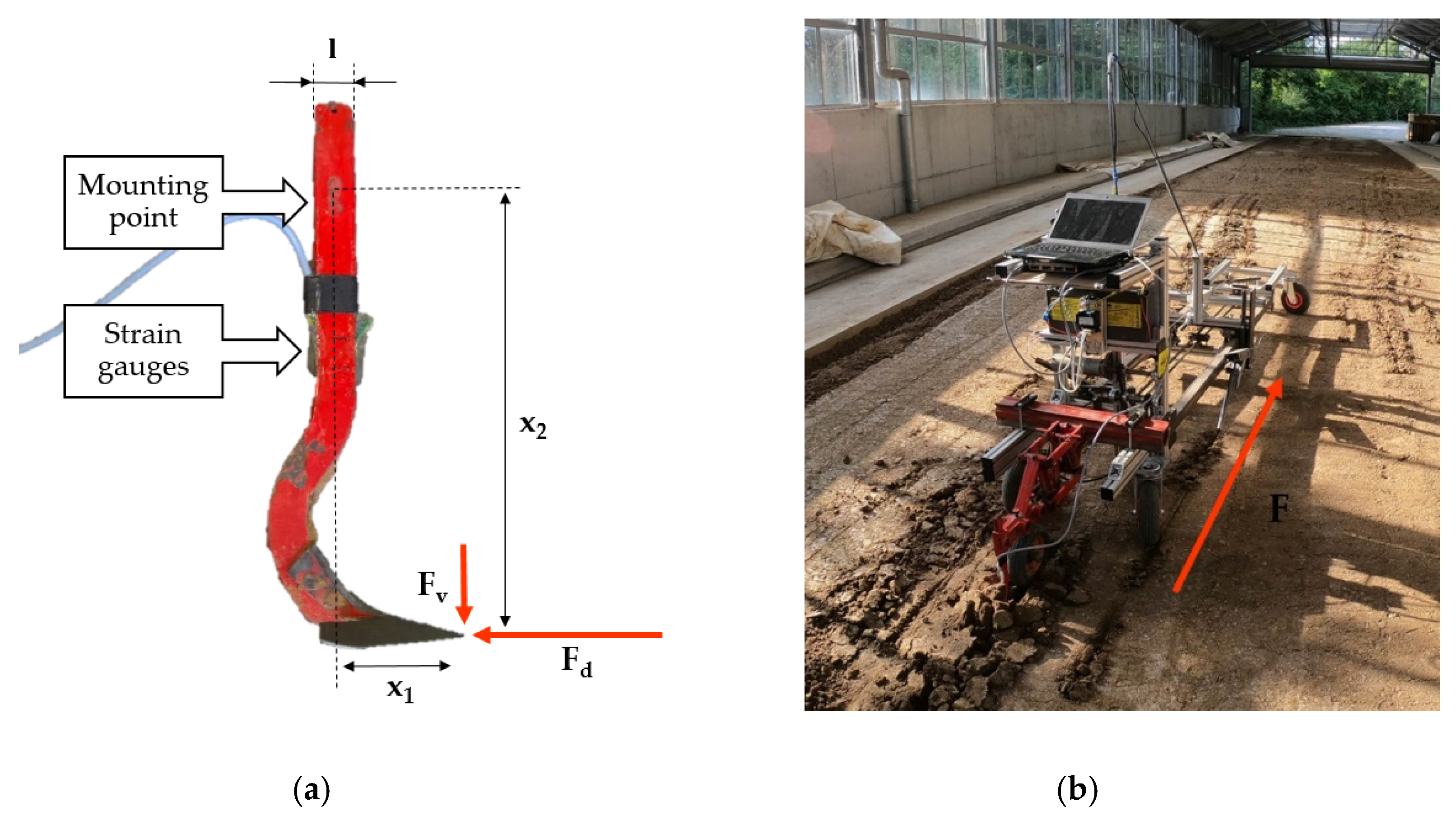
2.1. Soil Interaction Force

As described in [13], the tractive force F X of tires is directly dependent on the tire load F Z . The so-called net traction ratio (NTR) is described as:
N T R = F x F z .
The values of N T R are dependent on the soil shear strength and wheel slip. This N T R factor can reach values between 0.2 and 0.8 for soil under different conditions [14]. The impact factors are the soil type, moisture, soil shear strength on the subsoil, and individual tire parameters. Therefore, tire-based traction systems are always limited by the vehicle weight. As soon as a spike enters the soil, the shear strength of the soil can be used to create a counterforce to the applied traction force. Therefore, the maximum applicable force is dependent on the penetration depth and the spike cross-section. Spektor and Katz reported that the soil resistance force increases linearly with the tool width and non-linearly with the cutting depth [24]. They propose that the resistance force of the tested soil (sandy loam) F l i m be expressed with a specific soil coefficient r and a specific numerical exponent α depending on the soil conditions, cutting regime and tool geometry, velocity, and the cutting depth h in millimeters.
F l i m = r h α .
For a quasi-static regime at 0.1 mm/s and a tool width of 60 mm, they evaluated values of 2.5 N for r and 1.45 for α [24]. This would result in an F l i m of 2 kN at 100 mm and 5.4 kN at 200 mm penetration depth. At 300 mm depth, F l i m could reach 9.7 kN. Based on this evaluation, we formulate the following hypothesis: A spike having the same cross-section as the tool to be pulled and penetrating the soil deeper than the tool can create enough resistance force for the task.

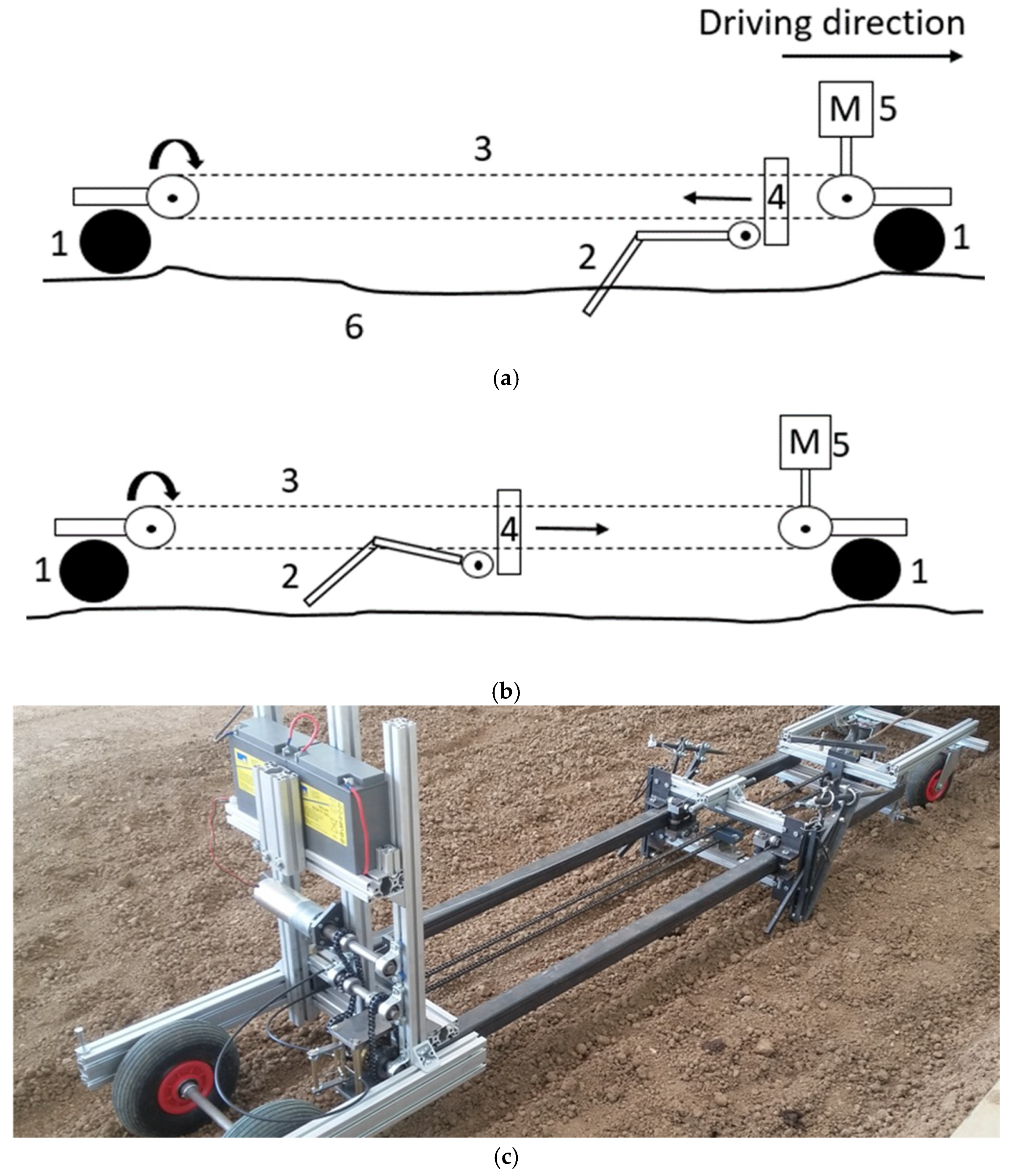
2.2. Movement of the Prototype

The developed prototype for testing this hypothesis works as follows (see Figure 1): A linear push-and-pull movement is generated with the help of a basic electric motor (5) and a chain (3) connected to a vertical slide (4). At each side of the slide, a passive movable spike (2) is connected, which could get stuck and enter the soil (6), depending on the driving direction of the slide. The whole vehicle is supported by four passive 360-degree movable castor wheels (1). There are two main states of the designed spikes, which support the robot’s forward motion: (1) as soon as the slide in the middle is moving against the driving direction, the spikes will penetrate the soil and will move the robot forward in the driving direction; (2) as soon as the slide arrives at the end of the frame, it will change direction. This change in direction pulls the passive spikes out of the soil, enabling the system to move the spikes back to the front of the vehicle. As soon as the slide reaches the front of the robot, the slide will change direction once more so that the spikes penetrate the soil again to create traction.
The penetration depth of the passive spikes depends on the cross-section, the applied draft force of the robot, and the soil penetration resistance. Therefore, the system self-regulates the necessary penetration depth of the spikes. As long as the penetration force of the spikes is higher than the shear strength of the soil, the spike will move deeper into the soil based on the momentum applied to the spike joint. The basic idea of using passive spikes for locomotion was first described by Bover in 2011 [22,25].

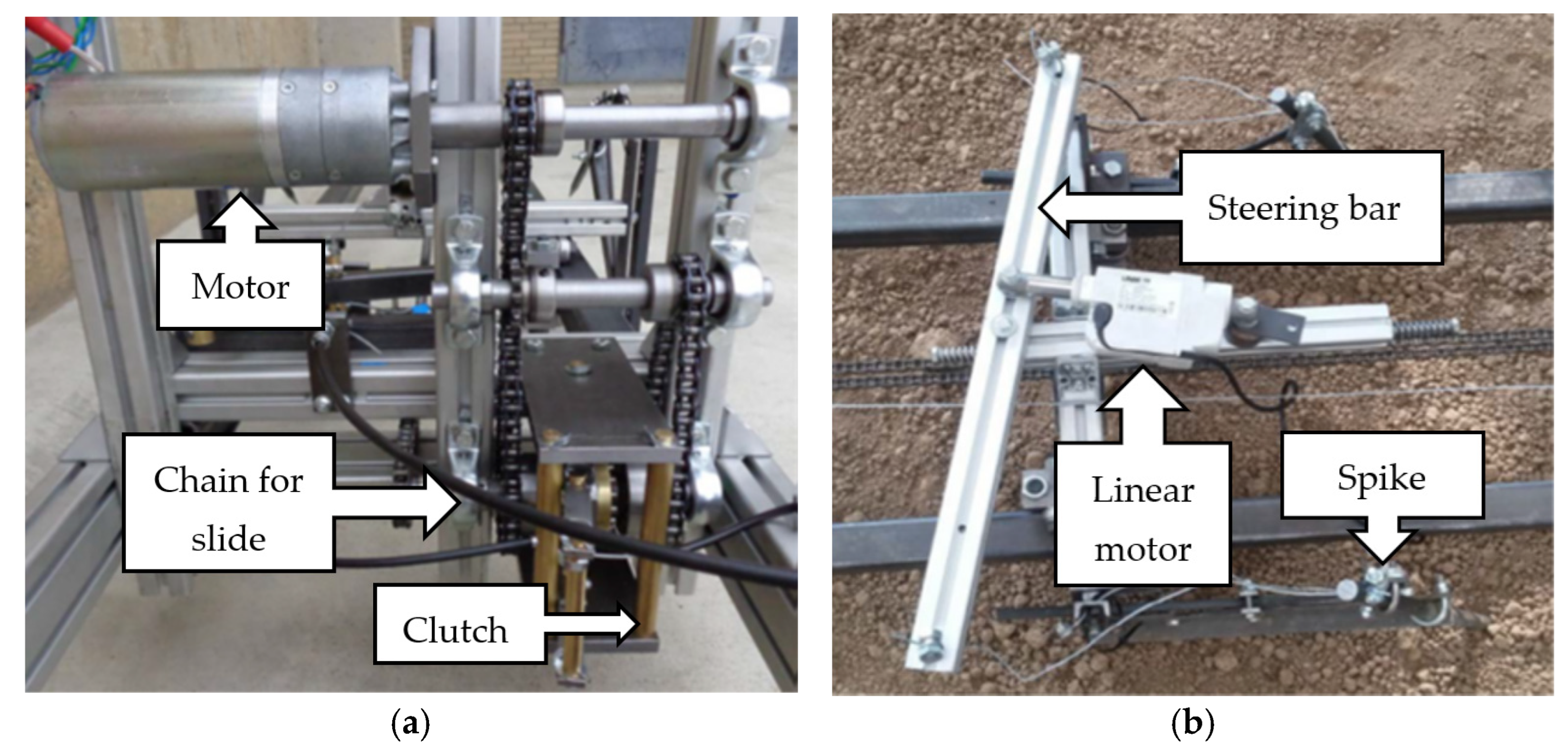
2.3. Mechanics and Control

To create the necessary movement, a linear guide was built based on two tubular profiles. They held a chain that moved a slide over the linear guide. The chain was connected to a gearbox, which was connected to a basic DC electrical motor with a nominal power of 120 W (BCI-63.55, emb-papst GmbH, Mulfingen, Germany). The spikes were attached with joints to the moving slide, one at each side of the machine. To switch the direction of the slide movement, a completely mechanical solution was chosen to be more robust and to minimize the control requirement and electrical components of the machine. At each end of the linear guiding tubes for the slide, a mechanical feeler was attached, which used a Bowden cable to switch the mechanical clutch of the motor on both sides. The clutch enabled a mechanical direction switch, without the need to start and stop the motor (see Figure 2a). The whole width of the system was fixed to 0.55 m so that the system would be able to drive between crop rows in agricultural applications with a 0.75 m row width. To enable the steering of the vehicle, both spikes were connected to an iron cable (1 mm diameter), which was connected to a horizontal steering bar (see Figure 2b).
This bar had a joint in the middle. An LA23 linear motor with a 1500 N pull force (Linak, Nordborg, Denmark) was attached and was able to switch the angle of the steering bar. The cable length was fixed in a way that either both spikes were able to enter the soil or one of the spikes was pulled into the air. Pulling out one of the spikes created a force misbalance, which resulted in momentum, turning the vehicle. As the whole vehicle was placed on small, 360-degree movable packer wheels, the system could follow the forces in each direction. The principle behind the turning mechanics is described by Reiser et al. (2019) in more detail [26]. As the speed of the vehicle was rather slow, no braking system was needed. The vehicle was held in place by the rolling resistance of the tires and the resistance of the implement used in the soil. These provided forces that counter-react to the forces of the spikes; therefore, no braking system was necessary.
For the control of the vehicle, an SDC2130 motor controller (Roboteq, Scottsdale, AZ, USA) was used and was connected to the drive motor and the linear steering motor. It was possible to control the whole vehicle based on a remote control directly connected to the motor controller or program a defined movement sequence. In the presented state, the control of the machine was based on odometry and predefined scripts to move. This was sufficient to navigate the machine. The applied voltage and current were recorded with the motor controller. The whole setup of the robot can be seen in Figure 3.
It was possible to attach basic tools for agricultural cultivation based on the work schedule and crop and soil conditions.
The robot was equipped with two batteries supplying a nominal voltage of 24 V and 17 Ah. A video of the moving prototype can be seen at the following link “https://youtu.be/YVKgDNJ7bdc (accessed on 1 September 2019)”. The conclusive and specified parameters of the robot can be seen in Table 1.

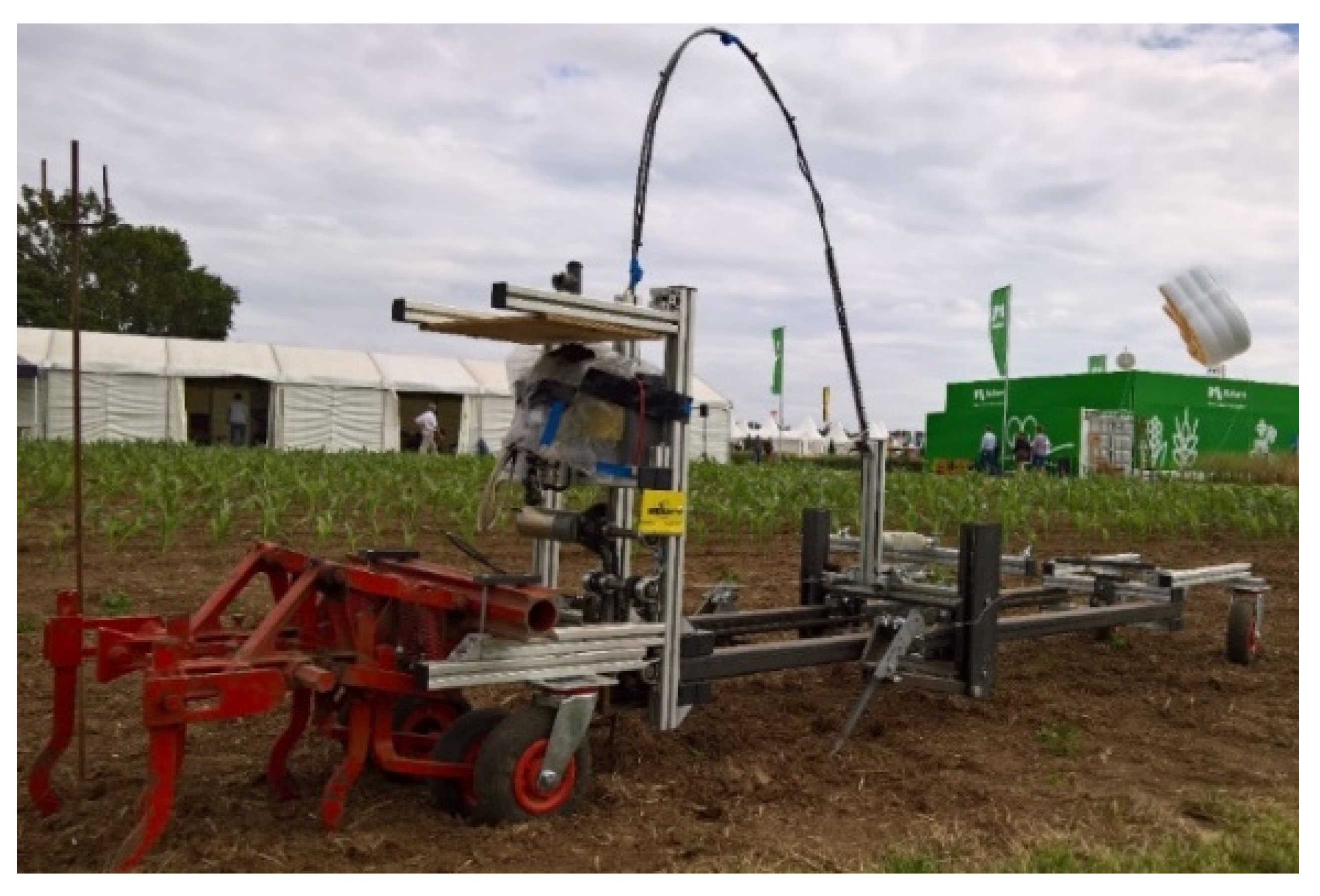
2.4. Experimental Setup

All experimental evaluations with the newly developed robot system were conducted in an indoor soil bin laboratory of the University of Hohenheim with a length of 46 m, 5 m width, and 1.2 m depth. The specific soil composition was 73% sand, 16% silt, and 11% clay. The soil bin was used to create uniform compaction levels of the soil and to avoid interference from biological plant materials like roots. The soil was prepared first by loosening it with a rotary harrow. Afterward, it was re-compacted using a flat roller. The specific soil parameters, like penetration resistance, moisture content, and shear strength, were determined.
To measure the interaction forces of the robot, a static stress experiment and a dynamic performance experiment were performed. In the static experiment, the vehicle was attached to a 3-axis load cell unit (see Figure 4a). The red tubes in the picture represent single-load cells. The arrangement of the load cells was constructed at the University of Hohenheim [27]. The load cell unit was fixed to a massive carrier plate and was connected with an iron rope to the robot (see Figure 4b).
The rope was fixed at the tool mounting point of the robot vehicle. The vehicle was turned on, and the horizontal pull on the load cell was gradually increased until either some part of the vehicle failed or the soil was not able to resist the applied force anymore. The time evolution of the generated force was recorded at high resolution with purpose-built software. The load cells were developed for a maximum draft force of 10 kN. The single-load cells had a measurement error of less than ±0.5%. The exact setup of the load cell unit was described in detail by [27].
For the dynamic performance experiment, the applied forces were measured while the robot performed a conventional soil preparation task. The power consumption of the battery and output system of the motor controller was logged simultaneously. At the back of the robot, a hoe was attached to the robot frame. Linear 350 ohm DY41-1.5 strain gauges (HBM GmbH, Darmstadt, Germany), with two parallel measuring grids and a full-bridge configuration, were attached to the hoe to determine the vertical and horizontal forces acting on the hoe (Figure 5a). The hoe was connected to the robot frame using a conventional hoe parallelogram to achieve a constant working depth (Figure 5b).
The depth of the tool was limited by an attached packer wheel, allowing a maximum penetration depth of 10 cm for the hoe. The forces on the hoe were measured based on a full-bridge mounting, using a one-half bridge on each side of the hoe. As just the horizontal draft forces were of interest, vertical and lateral forces were not a factor in the design of the mounting of the strain gauges. The strain gauges were placed at the front and the back of the hoe and were connected to a 9-pole pinout. This pinout was connected to an HBM Quantum MX840 analog-digital converter (HBM, Darmstadt, Germany). Using the HBM data acquisition software “Catman Easy”, the force model was calibrated based on static measurements. For calibration, the tool was fixed in the mounting position and was subsequently charged with a static force of three different values (1–10 kg). These values could later be used to calibrate the real forces from the collected strains. The strain forces were logged at 50 Hz.
The dynamic performance experiment consisted of moving the vehicle along 5 rows, each 10 m in length. The hoe was used as a reference point to measure the distance covered by the vehicle. To avoid initial conditions, the hoe was driven into the soil before the recording was started. For each row, untouched soil was used.

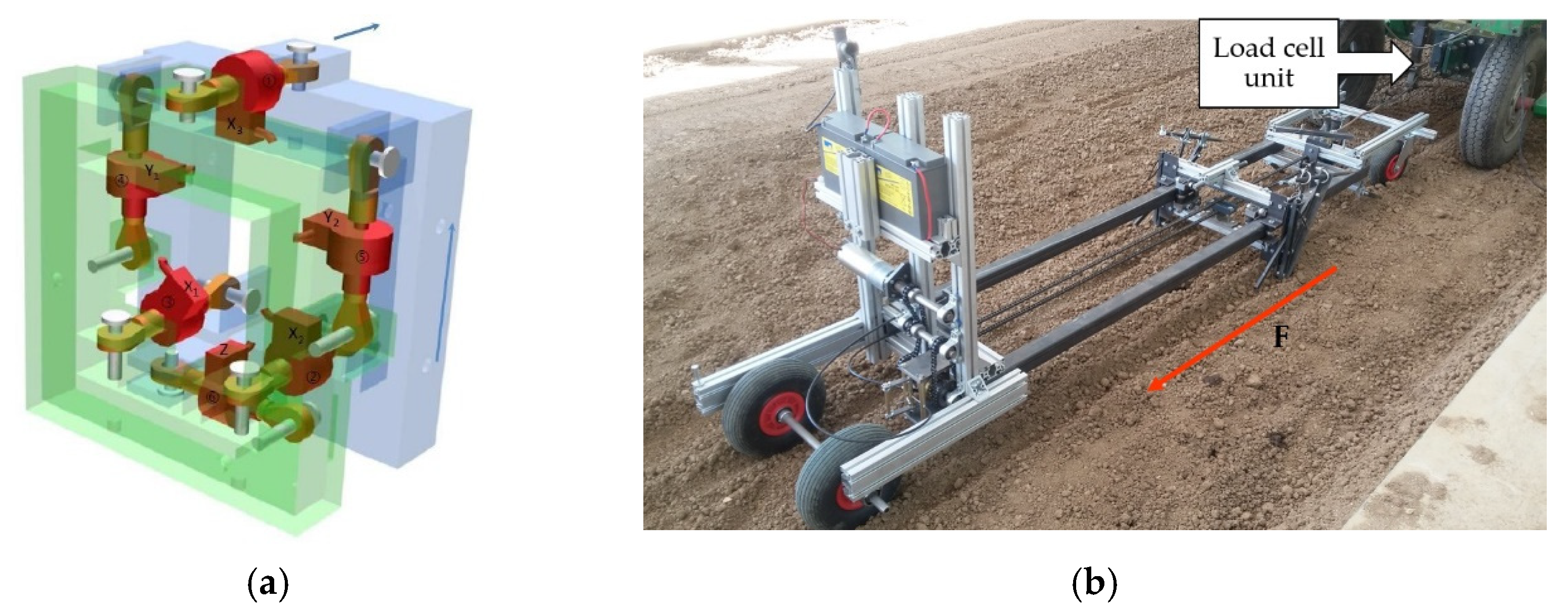
2.5. Determination of Draft Forces

To estimate the vertical and horizontal draft forces on the attached tool, the measured strain ϵ i of the strain gauges was measured. To define the relationship between the strain and forces, the moment of the vertical forces ( F v ) and horizontal forces ( F d ) at the strain point was derived as follows:
M i = F v x 1 = F d x 2 ,
where x j is the measured dimension of the moment arm for the vertical and horizontal forces, respectively. On the other hand, by employing the combination of the equilibrium expressions for the stress calculation, σ i = M / W and σ i = ϵ i E , the moment can also be expressed as follows:
M i = ϵ i E W ,
where E is Young’s modulus for steel, and W = l h 2 / 6 is the sectional modulus for the rectangular cross-section area of the hoe to which the strain gauges were attached. Substituting the left side of Equation (3) with the right side of Equation (4) and introducing W , the following final equations for vertical and draft forces can be obtained:
F v , d = i E l h 2 6 x j .
The values of the parameters measured for the tool are shown in Table 2.

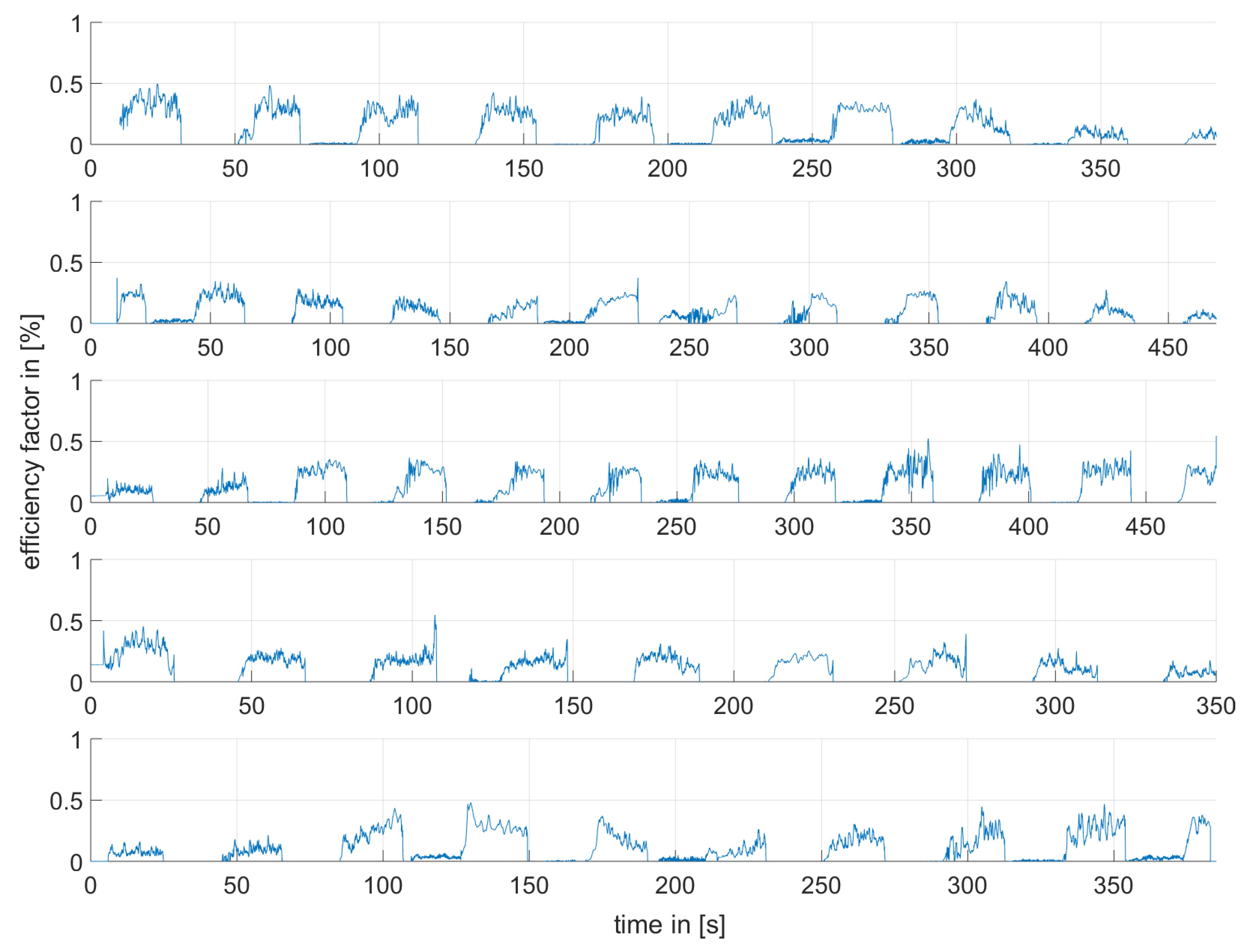
2.6. Overall Energy Efficiency Ratio

The energetic efficiency can be calculated as a ratio by dividing energy output by energy input. We calculate energy input from the electric current and voltage. Energy output is calculated from the horizontal force F d on the tool multiplied by the speed at which the tool has moved through the soil. We calculate the overall energy efficiency ratio (EER) η E E R as:
η E E R = E o u t E i n = F d v U I .
F d is the horizontal component of the draft force, and the speed v was calculated from the total distance of the vehicle and the overall duration time. The values of voltage U and current I were measured at the motor controller.

2.7. Soil Conditions at the Experimental Site

The penetration resistance, soil moisture content, and soil shear strength conditions were measured with an H-60 Hand-Held Vane Tester (GEONOR, Inc., Augusta, AZ, USA). The specific soil moisture was logged using a TRIME-PICo 64 Time-Domain-Reflectometry sensor (IMKO Micromodultechnik GmbH, Ettlingen, Germany). The penetration force was measured with an Eijkelkamp penetrometer logger (Eijkelkamp, Giesbeek, The Netherlands).
The overall shear strength was measured at 44 points and resulted in an average value of 32.9 kPa. The moisture content was measured at 20 different points, with an average of 8.5%. The soil resistance was measured at 24 different points with a penetrometer and resulted in a maximum shear strength of up to 1.5 MPa to a depth of 0.15 m. The soil was not completely uniform. In some areas, differences in soil compaction of up to 1 MPa were measured.

3. Results and Discussion

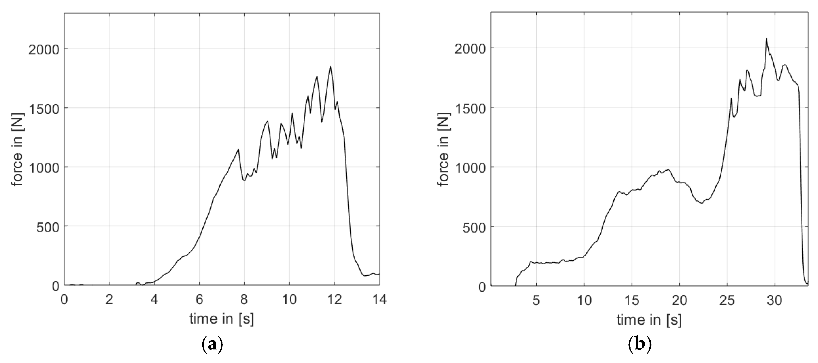
3.1. Static Stress Experiment

The results of the static measurements indicated that the vehicle generated high draft forces. Two trials were performed in two different locations in the soil bin. During the first trial, at maximum force, the soil failed such that the spikes broke loose and plowed through the soil. During the second trial, which was conducted under different soil conditions, the spikes failed such that they were bent backward and taken out of the soil. In both tests, as the power on the motor slowly increased, we observed an initial phase during which the robot needed some time to push the spikes into the soil. Afterward, the measured interaction force increased slowly. Our measurements indicate that this increase was not continuous but followed a wave pattern with small local peaks (see Figure 6a). Apparently, the force generated on the spikes dropped each time that either the soil failed or the spike penetrated deeper into the soil. The measured forces based on the three-axis load cell unit are shown in Figure 6.
During the first trial, we measured a maximum interaction force of 1853 N (see Figure 6a). During the second trial, we measured a peak horizontal force of 2082 N, which caused the spikes, with a diameter of 15 mm, to bend (see Figure 6b). Using Equation (1), we used the vehicle weight of 900 N and the peak force of 2082 N to calculate an NTR of 2.3 for the static stress experiment.
When using more robust materials and after improving the mechanical parts of the system, the NTR could be increased. But even when comparing the current design to an optimal NTR of 0.8 for tired vehicles on agricultural soil [13], the results indicate that a three-fold improvement can, in principle, be achieved with the interlocking drive system.

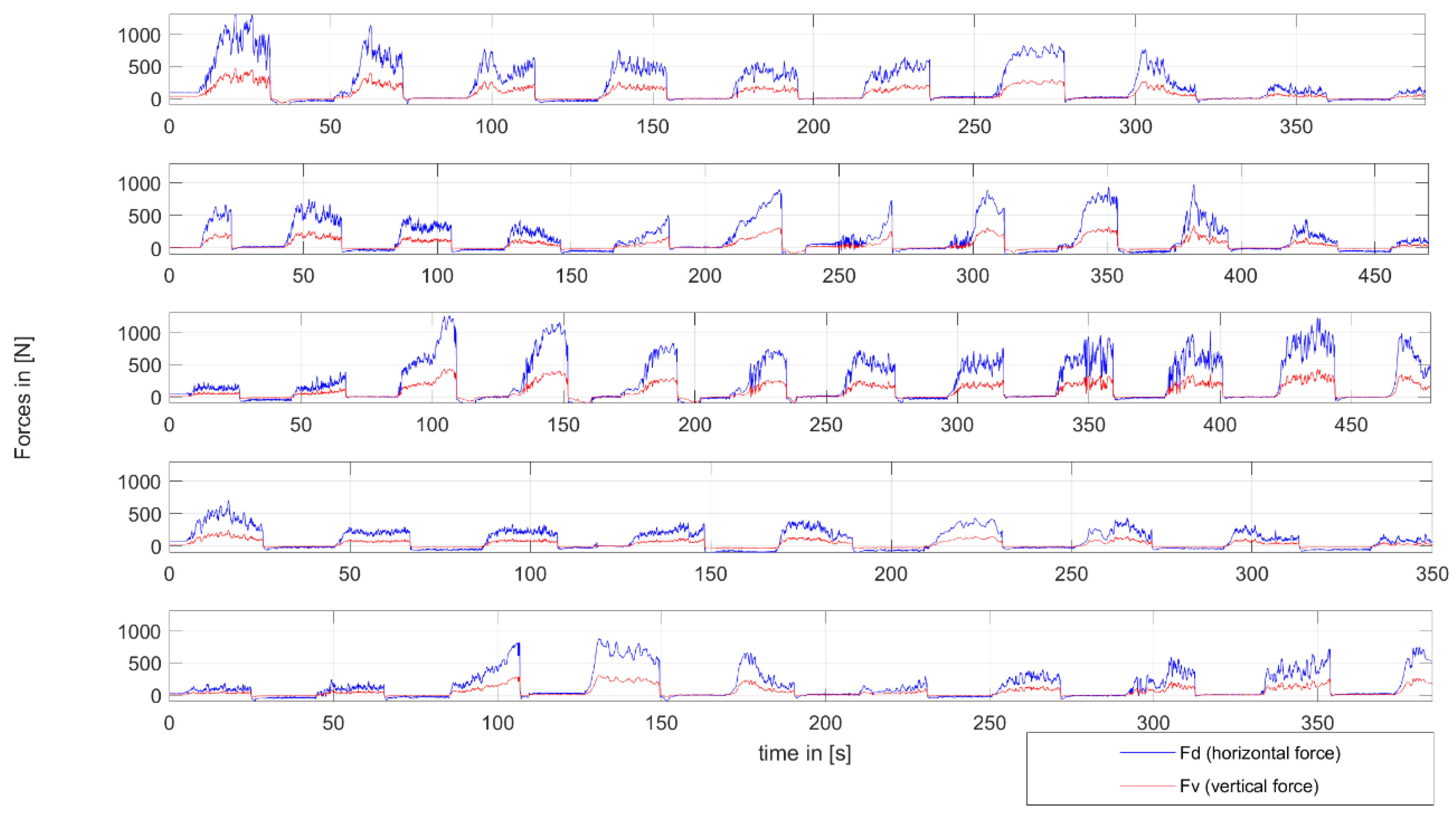
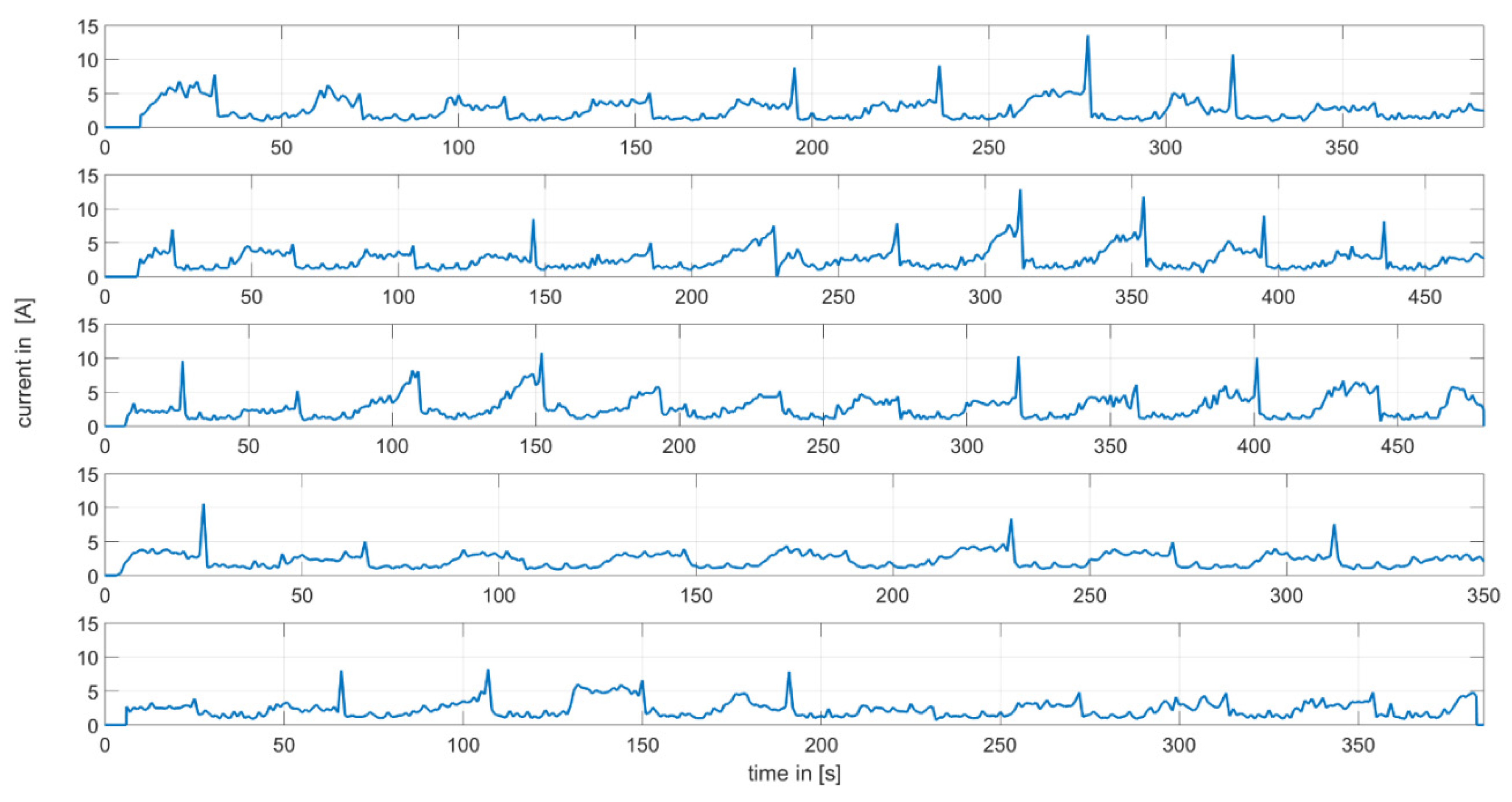
3.2. Dynamic Performance Experiment

The second experiment addressed the dynamic forces and energy efficiency of the interlock drive mechanism. The bent spikes from the first experiment were replaced with spikes with a diameter of 20 mm to avoid further material failures. Each cycle for pulling the slide back and pushing it forward to the front took around 44 s. Without the slippage of the spikes, a theoretical maximum distance of 1.5 m could be covered by the machine in one cycle. In reality, the vehicle spikes needed several centimeters to get a grip and to push the spikes deep enough into the soil to create the counterforce for the tool in the back. On average, the vehicle was able to move around 1 m forward during each cycle, and it took 415 s to cover a distance of 10 m. This equals a slip of 33%. As the soil was not completely uniformly compacted, several differences in the resistance and range of one cycle occurred. In Table 3 below, the median ( m ¯ ) , standard deviation (σ), and maximum value (max) for Fd, Fv, Ein, and Eout are described for each row of the dynamic measurement. For Fd and Fv, the idle times when the slide moved backward were excluded. The energy values Ein and Eout included all data from driving one row. The ratio η E E R per row is calculated using Equation (6).
The maximum force reached in the dynamic test was in row 1 with 1335.3 N, resulting in an NTR of 1.48. The maximum mean value was reached in row 3 with 502.5 N. The forces needed in row 2, row 3, and row 5 were significantly lower because of less soil compaction in these areas. Similar to the horizontal forces, the vertical forces were also the highest in row 1 with 461.7 N, and the mean value was the highest in row 3 with 172.7 N. The mean energy input Ein correlated with the force input, as high forces logically need more motor power to move forward. The mean input energy values varied between 65.1 W and 54.2 W for the five rows. With standard deviations below 37.7 W, the consumption of the vehicle just had some small peaks and reached the highest energy peak of 316.8 W in row 1. The η E E R ratio was, on average, between 0.1 and 0.17 for the five rows, including the idle time when the slide was moving back to the start position. The time it took to cover 10 m varied between a maximum of 478 s in row 3 and a minimum of 349 s in row 4. The time-specific results of all five trials for the horizontal and vertical forces can be found in Figure 7.
The forces showed slight peaks as soon as the vehicle moved forward and forced the tool to cut the soil. Most cycles were needed for row 2 and row 3, with 12 cycles. The fastest trial was performed with nine cycles for row 4. This was caused by loose soil that caused the vehicle to slip, causing longer cycle times and less movement for the robot. We observed that high forces could easily be generated during the dynamic movement of the system. In Figure 8 below, the corresponding current supplied to the motor over time is depicted.
It can be seen that switching the motor direction under load caused high peaks of amps for the motor, exceeding a maximum of 12 A. This was much higher than the current applied to the motor while moving the slide. When the motor was pushing the slide back, the motor drew, on average, 2 A. As soon as the tool was pulled from the anchored spikes, realizing their full load on the motor, we measured a value of up to 5 A. While pushing the spikes into the soil, the power consumption increased slowly until sufficient force to pull the tool was generated. We found that the robot consumed around 120 W when pulling the implement and 50 W when recovering the slide. Power consumption peaked at 316.8 W when switching the clutch under high load, something that can be avoided in future designs by using electrical switches or optimizing the clutch mechanics.
The energy efficiency ratio (EER) of the vehicle depended on the interlocking of the spikes with the soil and on whether the vehicle was pulling or recovering the slide. As long as the vehicle was recovering the slide, no work was performed, causing the efficiency factor to be zero (see Figure 9).
While the vehicle was pulling the tool, we observed an efficiency factor of up to 0.54. Low slip rates increased the efficiency (see also Table 1). For the five rows, the maximum values reached between 0.37 and 0.54. The best mean performance was achieved in line 1 and line 4. The worst result was reached in line 2. It seems that high efficiency is dependent on the forces developed. Especially for areas with small operation resistance, the EER dropped, leading to the assumption that the machine needs resistance and good machine utilization to perform effectively. The overall mean EER measured was 0.14. However, the peaks of the EER promise high improvement potentials, up to a value of 0.5.
Most losses occurred directly in the motor and the gearbox, transforming the electrical energy into mechanical movement. Optimizing the operation speed of the electric motor could improve power transmission and losses. However, the biggest improvement in the EER is expected when the principle can be converted to constant movement to get rid of the push-and-pull mechanism. The values include all losses in the process, like friction, penetration of the spikes into the soil, mechanic failures, and gearbox efficiency. Therefore, the EER could be increased by using lightweight construction, minimizing the slip of the vehicle, and optimizing the spike diameter and number. Decreasing the wheel-ground contact could help to decrease friction. However, comparable measurements of fuel consumption and energy efficiency in tractors reached an EER of 0.2. Therefore, the authors believe this principle has the potential to decrease the energy consumption for machine operation.
A comparable field operation for our robot would be the primary tillage of firm loamy sand with a sweep plow. In an operating environment where the use of heavy machinery and the associated compaction of the deeper soil can be avoided by a fleet of small robots, this is likely the most energy-intensive tillage operation. According to [28], cultivating firm, coarse-textured soil to a depth of 10 cm with a 12 cm wide sweep plow, as used here, requires a draft force of 470 ± 210 N. To compare, according to [28], a less energy-intensive operation like seedbed preparation with a coil tine harrow requires a draft force of 150 ± 30 N, and weeding with a rod weeder requires a draft force of 85 ± 20 N, both calculated for the same 12 cm operating width as before and at a tillage depth of 5 cm. Given that the vehicle performed well at a peak draft of over 2 kN, it seems plausible that this vehicle can pull harrows and weeders with an operating width of at least 1 m under realistic field conditions. For performing the weeding, the robot could use hoes and knives to cover the inter-row area and additional finger weeders for the intra-row space. When the crop plants are seeded in square patterns, the robot could pass the field with the same tools from two sides to perform the weeding.
The overall performance of the robot was better than expected by the authors. It was shown that the NTR could be increased based on the mechanical design by using spikes to enter the soil. The vehicle proved that it could be possible to create small robots that generate high interaction forces for agricultural applications using conventional tools. However, the prototype also revealed some issues that need further improvement. First, the speed of the machine was limited to 0.02 m/s, which is quite slow to cover large areas. The speed of the machine could be increased, but we do not believe that this would optimize the EER. The optimal speed, compared to high EER, has to be evaluated in future research. The machine can work in big swarms and perform 24/7 work. This 24/7 work would require more energy to be supplied to the machine but seems possible with existing technologies like Lithium-Polymer accumulators. When assuming a general energy consumption of 80 W per hour, which is consistent with the dynamic performance experiments performed, 1920 Wh should be sufficient to enable the robot to work for 24 h. Combined with a solar panel, the batteries could be recharged while working in the daytime. For an estimated energy density of Lithium-Polymer batteries with 190 Wh/kg, a battery pack of 10 kg would be sufficient. The actual lead battery pack weighs 12 kg. Moving to better technologies would be more than sufficient to power the system for 24 h.
The mechanical switching of the direction of the prototype makes the system more robust for outdoor environments. However, the high peak for the motor needs more mechanical care or a better solution to get rid of this high energy loss. Future prototypes could combine wheeled or caterpillar-like robots with traction systems like the prototype described in the article. This combination could make a continuous force generation possible and could get rid of the 50% time loss from bringing the slide back to the starting position. Even a two-gear system could be possible, making a slow gear for moving forward and making a fast gear for running the slide back. For future autonomous work, additional sensors are needed, like collision sensors and the integration of global satellite navigation systems. Additionally, the off-road capability should be improved to avoid malfunctions.

4. Conclusions

We developed an agricultural robot for weed control and soil cultivation based on a novel interlocking drive system and validated the design in a soil bin in a static stress experiment and a dynamic performance experiment. The stress experiment showed that the current design achieves an NTR of 2.31. The fact that the limiting factor was a material failure, not vehicle weight, suggests that an even higher NTR is possible by reinforcing the design of the spikes. Given the overall low weight of 900 N, we conclude that high traction with less compaction is possible. During the performance test, we found that the robot successfully cultivated the soil during all trials. While a maximum pull force of 2082 N was generated during the static stress experiment, pull forces of up to 1335.3 N were generated in the dynamic performance experiment for a sustained NTR of 1.48 while cultivating the soil. This parameter depends on the attachment and tool arrangement and could reach higher values. The average power consumption of 59.2 W is low enough to enable the system to work 24/7 when powered by more batteries and/or a solar panel. The EER of the entire drive train was up to 0.54, calculated by comparing the work performed to the input power supplied by the battery. However, the overall EER should be improved. Our laboratory experiments confirm that the interlock drive mechanism has a strong potential to realize energy-efficient and powerful applications for small and lightweight autonomous agricultural robots. All of this would assist in the next step of the work, where the optimization of the developed system for better efficiency should be thoroughly addressed.

Author Contributions

Funding acquisition, data, and writing—original draft preparation: D.R.; software, visualization, validation, and formal analysis: G.M.S. and D.R.; investigation, conceptualization, resources, and methodology: G.H. and D.R.; writing—review and editing: G.M.S., V.N. and D.R.; supervision and project administration: H.W.G. All authors have read and agreed to the published version of the manuscript.

Funding

This research received no external funding.

Institutional Review Board Statement

Not applicable.

Acknowledgments

The authors thank the companies Mädler and Linak for their support in providing the material to build the prototype. Additionally, we want to thank the three unknown reviewers who helped with their comments to improve the quality of the paper.

Conflicts of Interest

The authors declare no conflict of interest.

References

  1. BMU Klimaschutzplan 2050—Klimaschutzpolitische Grundsätze und Ziele der Bundesregierung. 2016, Volume 4, p. 11. Available online: www.bmwk.de (accessed on 17 July 2023).
  2. Fountas, S.; Gemtos, T.A.; Blackmore, S. Robotics and Sustainability in Soil Engineering BT—Soil Engineering; Dedousis, A.P., Bartzanas, T., Eds.; Springer: Berlin/Heidelberg, Germany, 2010; pp. 69–80. ISBN 978-3-642-03681-1. [Google Scholar]
  3. Paraforos, D.S.; Aubé, C.; Athanasakos, L.; Avgoustakis, I.; Baron, S.; Bresilla, T.; Fountas, S.; Hemming, J.; Karagiannis, P.; Mylonas, N.; et al. Connecting Agricultural Robots and Smart Implements by Using ISO 11783 Communication. In Proceedings of the 7th IFAC Conference on Sensing, Control and Automation Technologies for Agriculture, Munich, Germany, 14–16 September 2022; Volume 62, pp. 123–133. [Google Scholar]
  4. Blackmore, B.S.; Griepentrog, H.W.; Fountas, S. Autonomous Systems for European Agriculture. In Proceedings of the Automation Technology for Off-Road Equipment, Bonn, Germany, 1–2 September 2006. [Google Scholar]
  5. Johnson, D.A.; Carolina, N.; Naffin, D.J.; Puhalla, J.S.; Dakota, N.; Wellington, C.K. Development and Implementation of a Team of Robotic Tractors for Autonomous Peat Moss Harvesting. J. Field Robot. 2009, 26, 549–571. [Google Scholar] [CrossRef] [Green Version]
  6. Vougioukas, S.G. A Distributed Control Framework for Motion Coordination of Teams of Autonomous Agricultural Vehicles. Biosyst. Eng. 2012, 113, 284–297. [Google Scholar] [CrossRef]
  7. Floreano, D.; Wood, R.J. Science, Technology and the Future of Small Autonomous Drones. Nature 2015, 521, 460–466. [Google Scholar] [CrossRef] [PubMed] [Green Version]
  8. Reiser, D.; Sehsah, E.; Bumann, O.; Morhard, J.; Griepentrog, H.W. Development of an Autonomous Electric Robot Implement for Intra-Row Weeding in Vineyards. Agriculture 2019, 9, 18. [Google Scholar] [CrossRef] [Green Version]
  9. Ruckelshausen, A.; Biber, P.; Dorna, M.; Gremmes, H.; Klose, R.; Linz, A.; Rahe, F.; Resch, R.; Thiel, M.; Trautz, D.; et al. BoniRob: An Autonomous Field Robot Platform for Individual Plant Phenotyping. In Proceedings of the Joint International Agricultural Conference, Wageningen, The Netherlands, 6–8 July 2009; Volume 9, pp. 841–847. [Google Scholar]
  10. Martínez-Guanter, J.; Garrido-Izard, M.; Valero, C.; Slaughter, D.C.; Pérez-Ruiz, M. Optical Sensing to Determine Tomato Plant Spacing for Precise Agrochemical Application: Two Scenarios. Sensors 2017, 17, 1096. [Google Scholar] [CrossRef] [PubMed] [Green Version]
  11. Aneke, M.; Wang, M. Energy Storage Technologies and Real Life Applications—A State of the Art Review. Appl. Energy 2016, 179, 350–377. [Google Scholar] [CrossRef] [Green Version]
  12. Hamza, M.A.; Anderson, W.K. Soil Compaction in Cropping Systems: A Review of the Nature, Causes and Possible Solutions. Soil Tillage Res. 2005, 82, 121–145. [Google Scholar] [CrossRef]
  13. Schreiber, M.; Kutzbach, H.D. Influence of Soil and Tire Parameters on Traction. Res. Agric. Eng. 2008, 54, 43–49. [Google Scholar] [CrossRef] [Green Version]
  14. Kliefoth, F. Zugkraft, Fahrgeschwindigkeit und Gewicht der Schlepper. Landtech. Forsch. 1953, 3, 117–124. [Google Scholar]
  15. Bentzien, U. Landmaschinentechnik in Mecklenburg (1800 Bis 1959). In Jahrbuch für Wirtschaftsgeschichte; Akademie Verlag: Berlin, Germany, 1965; Volume 6, pp. 54–81. [Google Scholar]
  16. Abrahám, R.; Majdan, R.; Drlička, R. Possibilities of Improving the Wheel Tractor Drive Force Transmission to Soil. Res. Agric. Eng. 2015, 61, S37–S42. [Google Scholar] [CrossRef] [Green Version]
  17. Federle, W. An Integrative Study of Insect Adhesion: Mechanics and Wet Adhesion of Pretarsal Pads in Ants. Integr. Comp. Biol. 2002, 42, 1100–1106. [Google Scholar] [CrossRef] [PubMed]
  18. Romão, J.C.; Tavakoli, M.; Viegas, C.; Neto, P.; De Almeida, A.T. InchwormClimber: A Light-Weight Biped Climbing Robot with a Switchable Magnet Adhesion Unit. In Proceedings of the IEEE/RJS International Conference on Intelligent Robots and Systems (IROS), Hamburg, Germany, 28 September–3 October 2015; pp. 3320–3325. [Google Scholar]
  19. Patronik, N.A.; Ota, T.; Zenati, M.A.; Riviere, C.N. Synchronization of Epicardial Crawling Robot with Heartbeat and Respiration for Improved Safety and Efficiency of Locomotion. Int. J. Med. Robot. Comput. Assist. Surg. 2012, 8, 97–102. [Google Scholar] [CrossRef] [PubMed] [Green Version]
  20. Spenko, M.J.; Haynes, G.C.; Saunders, J.A.; Cutkosky, M.R.; Rizzi, A.A. Biologically Inspired Climbing with a Hexapedal Robot. J. Field Robot. 2008, 25, 223–242. [Google Scholar] [CrossRef] [Green Version]
  21. Christensen, D.L.; Hawkes, E.W.; Suresh, S.A.; Ladenheim, K.; Cutkosky, M.R. Μtugs: Enabling Microrobots to Deliver Macro Forces with Controllable Adhesives. In Proceedings of the IEEE International Conference on Robotics and Automation, Seattle, WA, USA, 26–30 May 2015; pp. 4048–4055. [Google Scholar]
  22. Bover, D. Autonomous Self-Actuated Ploughing Implement. U.S. Patent No. 9,144,188 B2, 29 September 2015. [Google Scholar]
  23. Nannen, V.; Bover, D.; Reiser, D.; Zöbel, D. Motion Study of Spike Entering the Soil of the Interlock Drive System. In Proceedings of the 21st ISTRO International Conference, Paris, France, 24–27 September 2018; pp. 405–406. [Google Scholar]
  24. Spektor, M.; Katz, M. Experimental Study of Frontal Resistance Force in Soil Cutting. J. Terramech. 1985, 22, 127–133. [Google Scholar] [CrossRef]
  25. Nannen, V.; Bover, D.; Zöbel, D. A Novel Traction Mechanism Based on Retractable Crampons to Minimize Soil Compaction and Reduce Energy Consumption. engrxiv 2017. preprint. [Google Scholar] [CrossRef]
  26. Reiser, D.; Nannen, V.; Hubel, G.; Griepentrog, H.W. Design, Modelling and Control of a Novel Agricultural Robot with Interlock Drive System. In Proceedings of the IEEE/RJS International Conference on Intelligent Robots and Systems (IROS), Macau, China, 4–8 November 2019; pp. 5520–5525. [Google Scholar]
  27. Magenau, T. Entwicklung Eines Mobilen Prüfstands zur Untersuchung der Rad-Boden-Schnittstelle Bei Hangfahrten; University of Hohenheim: Stuttgart, Germany, 2008. [Google Scholar]
  28. ASAE D497.5 FEB2006; ASABE Agricultural Machinery Management Data; American Society of Agricultural and Biological Engineers: Saint Joseph, MI, USA, 2006.
Figure 1. (a,b) The basic principle of the prototype to move forward described with two different positions of the spikes with mechanical components (1—wheels; 2—spikes; 3—chain; 4—slide; 5—motor; 6—soil) and (c) general overview of the setup.
Agriculture 13 01510 g001
Figure 2. Description of the mechanical parts for the motor gear, clutch, and direction change (a) and the setup for the steering mechanism (b).
Agriculture 13 01510 g002
Figure 3. Complete machine for performing a weeding task in an outdoor environment.
Agriculture 13 01510 g003
Figure 4. Load cell unit for measuring the maximum possible interaction force F (a) and the whole setup with the robot (b). The arrow describes the direction of the pulling force.
Agriculture 13 01510 g004
Figure 5. Placement of the strain gauges on the tool (a) and the tool in the working position of the robot (b).
Agriculture 13 01510 g005
Figure 6. Maximum horizontal forces based on the (a,b) two trials of the static stress experiment in the soil bin.
Agriculture 13 01510 g006
Figure 7. Graph of the measured forces for the five trial rows of the dynamic performance experiment.
Agriculture 13 01510 g007
Figure 8. Motor current consumption (A) dependent on time for the five dynamic measurements.
Agriculture 13 01510 g008
Figure 9. Overall energy efficiency factor for the five trials of the dynamic performance experiment, calculated as the output energy divided by the input energy.
Agriculture 13 01510 g009
Table 1. Specifications of the robot.
Main Specifications of the Robot
Power of DC motor (W)120
Number of spikes2
Fixed width of the robot (m)0.55
Operation row width (m)0.75
Pull force of the LA23 linear motor (N)1500
Type of the used motor controllerSDC2130
Nominal voltage supply (V)24
Supplied current (Ah)17
Table 2. Values used for the lever arms and strain points while estimating the forces on the tool.
NameValueUnit
E2,100,000(N/m²)
l0.028(m)
h0.01(m)
X10.065(m)
X20.188(m)
Table 3. Data of the measured forces (Fd, Fv), energy consumption (Ein, Eout), and energy efficiency ratio ( η E E R ) with mean values ( m ¯ ) , standard deviations (σ), and maximum peak values (max), separated for the five rows of the dynamic test.
Fd (N)Fv (N)Ein (W)Eout (N*m/s)
η E E R
Row No.Me (s)
m ¯
σMax
m ¯
σAx
m ¯
σAx
m ¯
σMax
m ¯
1389436.8264.21335.3149.791.8461.762.236.1316.810.614.265.30.17
2468333.9226.4973.9113.078.8336.759.437.1299.35.710.040.60.10
3478502.5293.41260.3172.7101.9435.865.137.7250.69.913.852.10.15
4349228.4108.2706.878.337.8244.455.125.2245.95.58.739.30.16
5383295.5214.3872.9100.674.3301.354.229.0191.96.910.744.70.13
Disclaimer/Publisher’s Note: The statements, opinions and data contained in all publications are solely those of the individual author(s) and contributor(s) and not of MDPI and/or the editor(s). MDPI and/or the editor(s) disclaim responsibility for any injury to people or property resulting from any ideas, methods, instructions or products referred to in the content.

