
Simulation Research on Cotton Stalk Cutting and Crushing Based on ANSYS/LS-DYNA and Field Experiments

Abstract
:1. Introduction
2. Materials and Methods
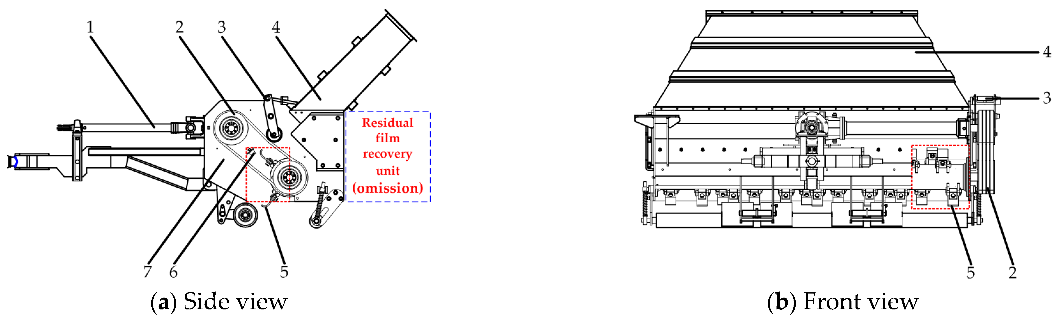
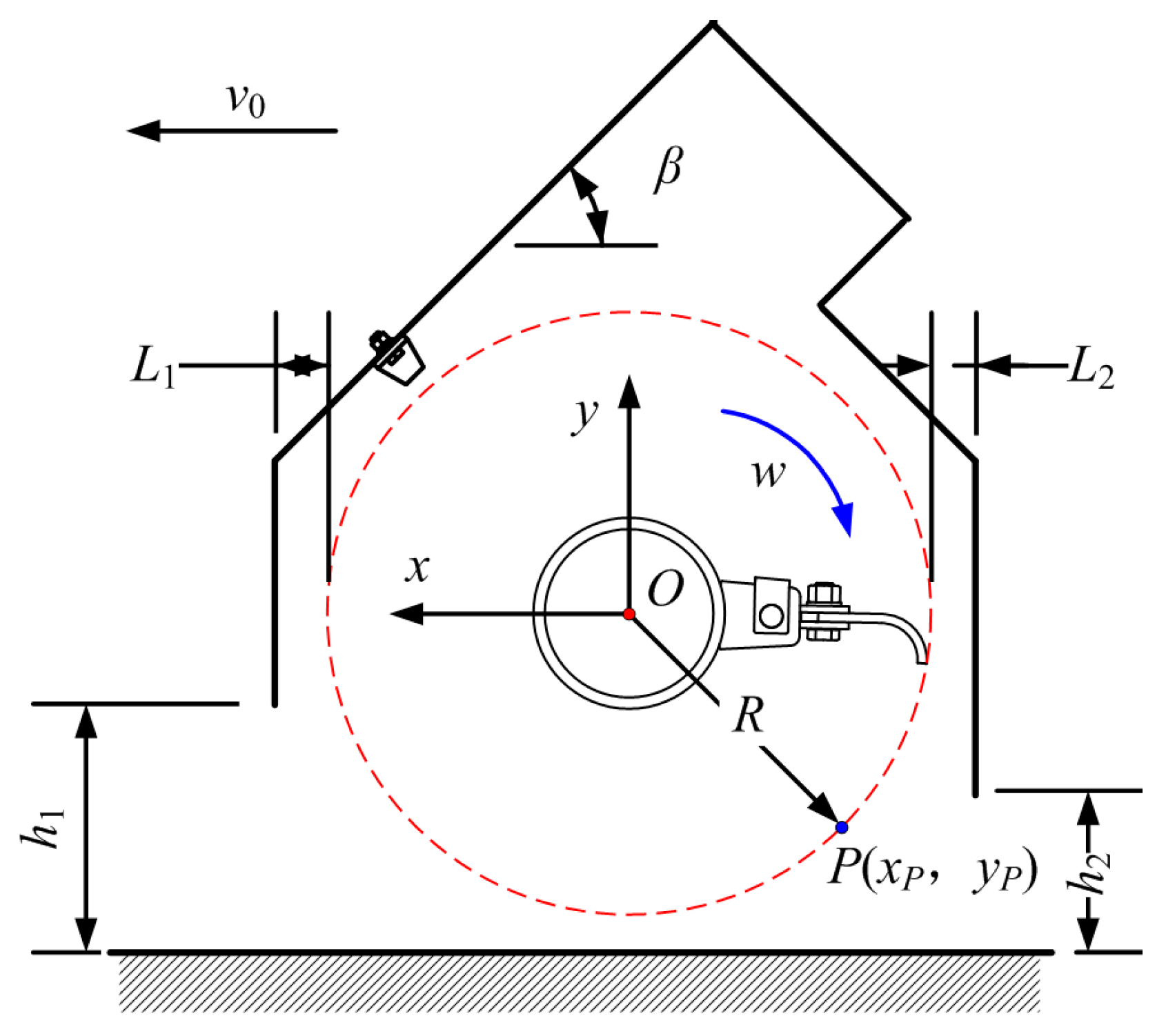
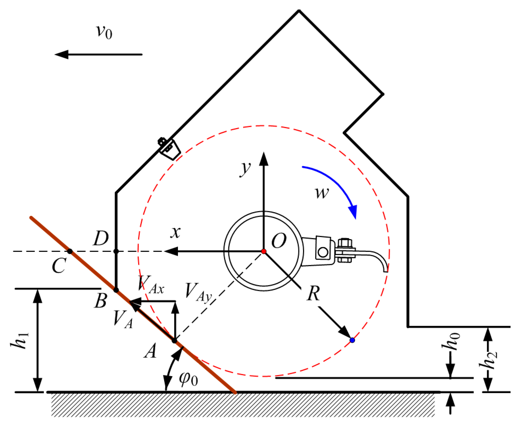
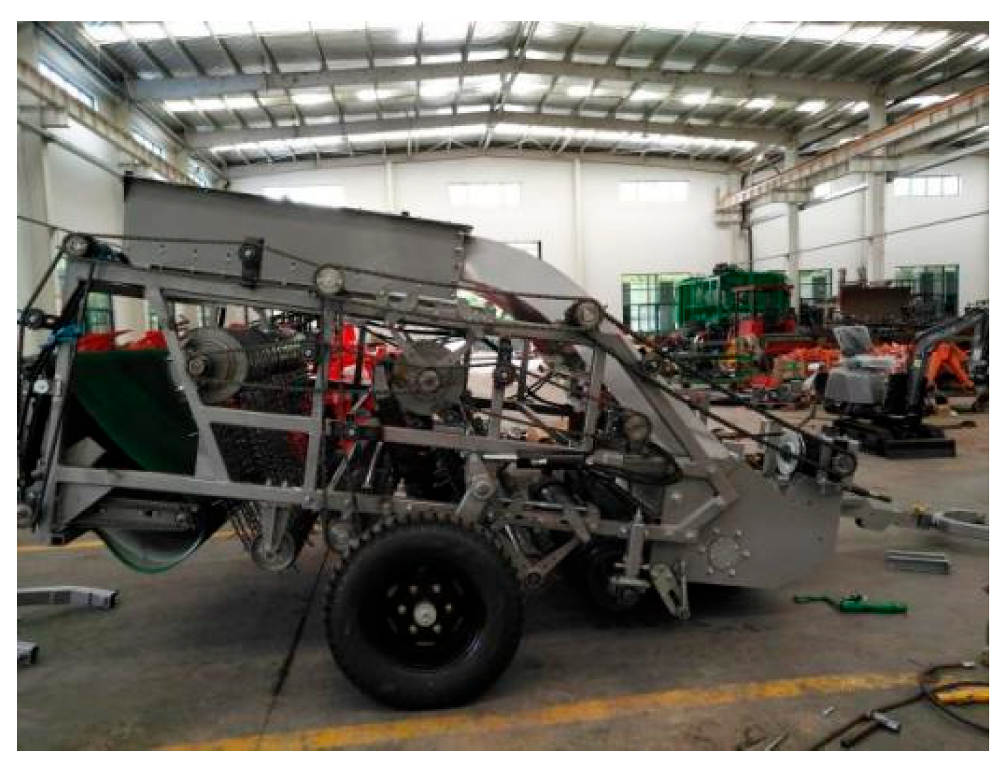
2.1. Structure of the Front-Mounted Cotton-Straw-Crushing Device
2.2. Working Principle
3. Design of the Key Components and Parameter Determination
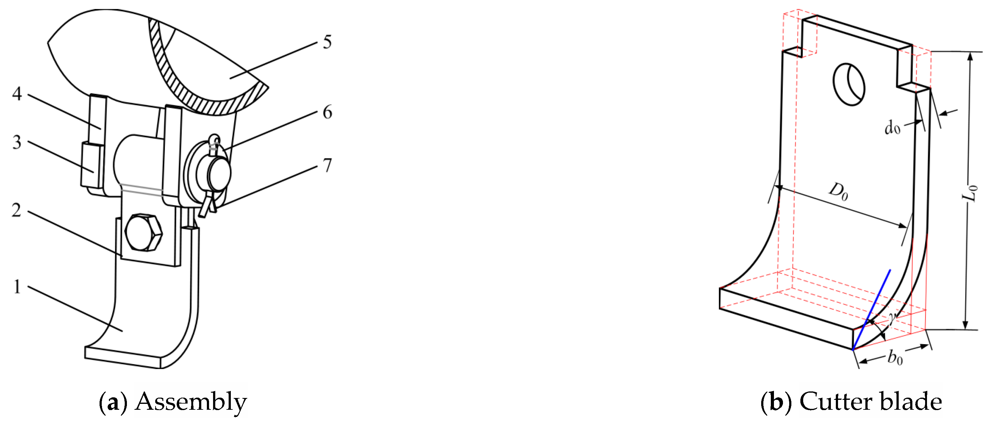
3.1. Cutter Blade
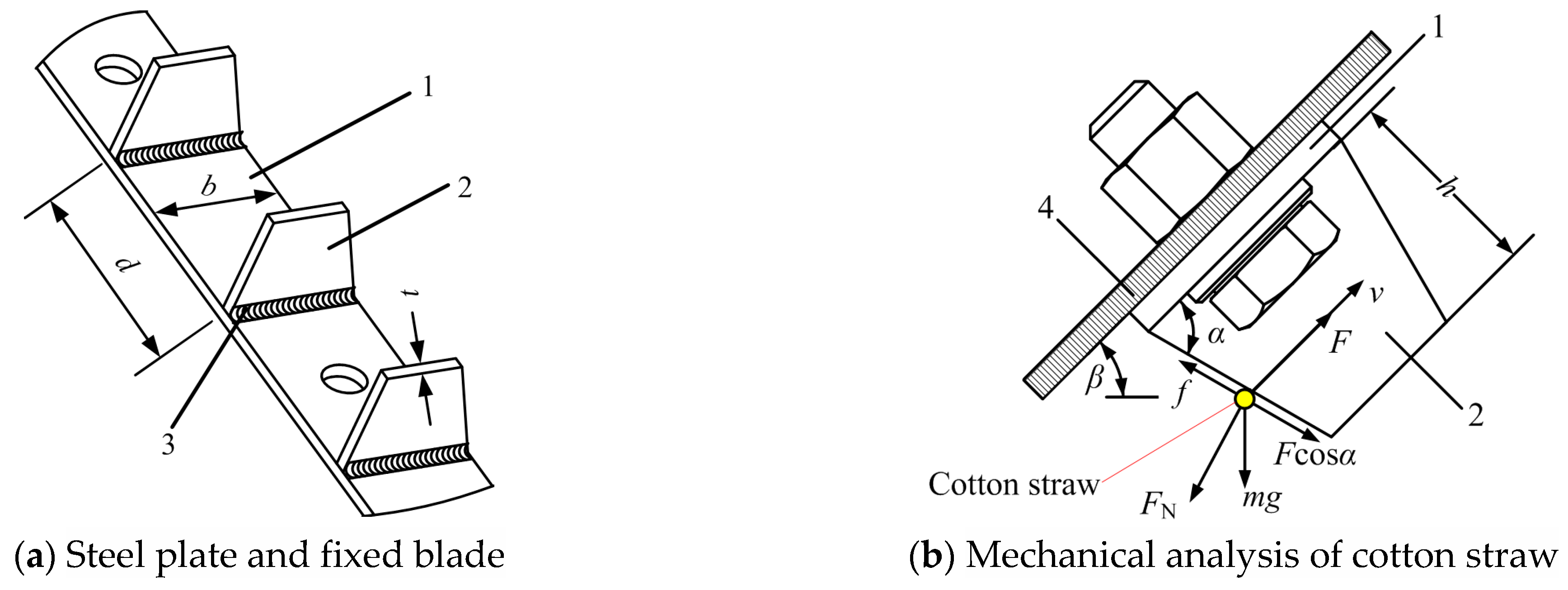
3.2. Fixed Blades
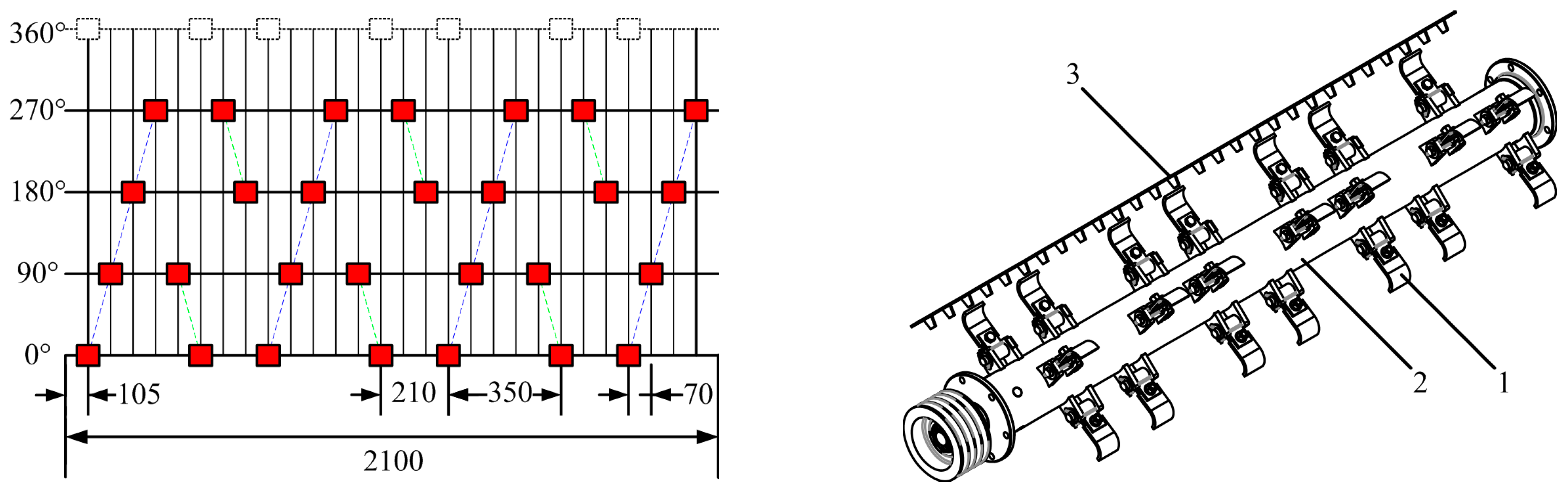
3.3. Crushing Chamber
4. Analysis and Establishment of an Explicit Dynamic Model
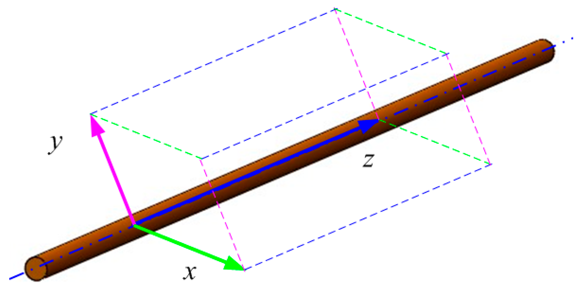
4.1. Geometric Model of a Cotton Stalk
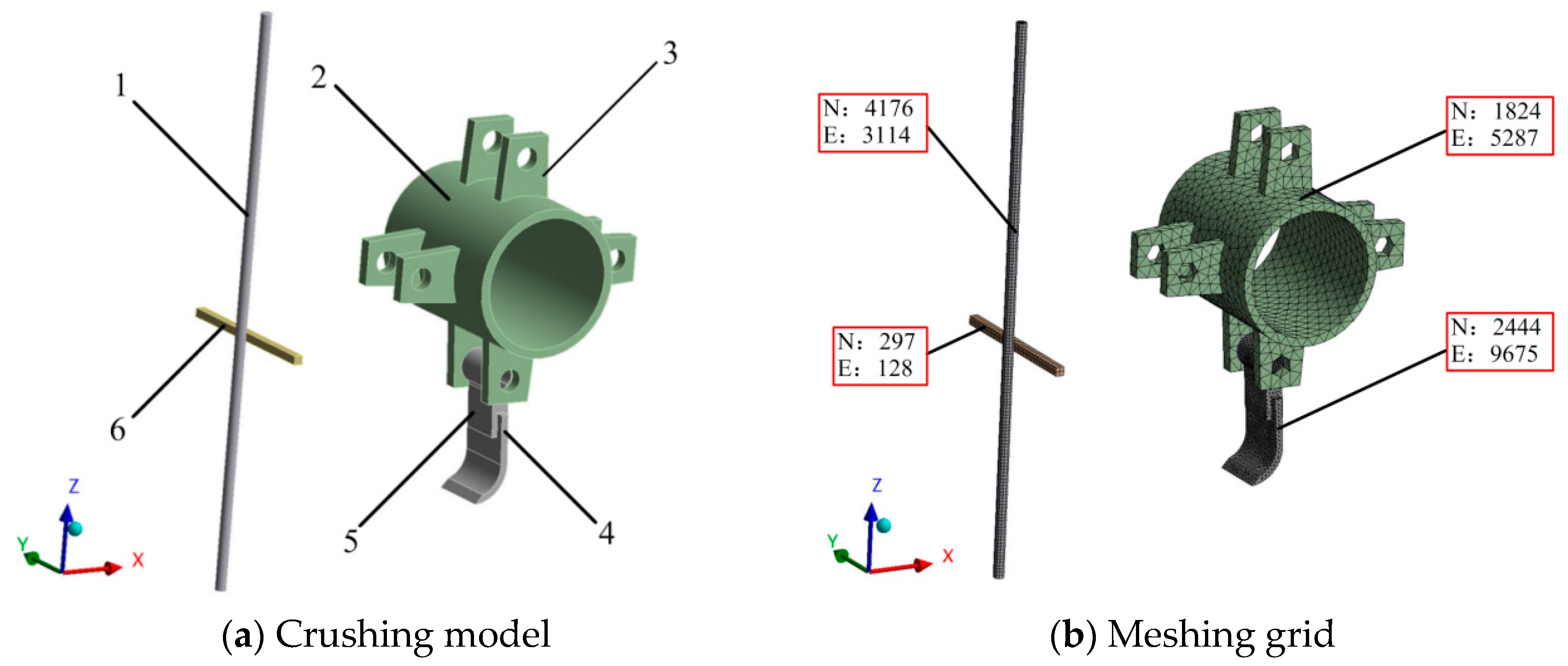
4.2. Cutting Model and Meshing Grid
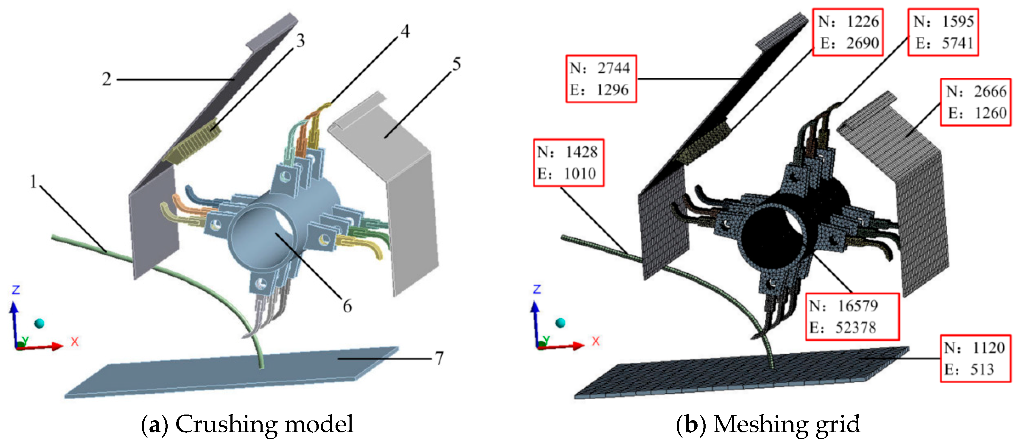
4.3. Crushing Model and Meshing Grid
4.4. Material Properties
4.5. Contact and Constraints
5. Simulation Results and Analysis
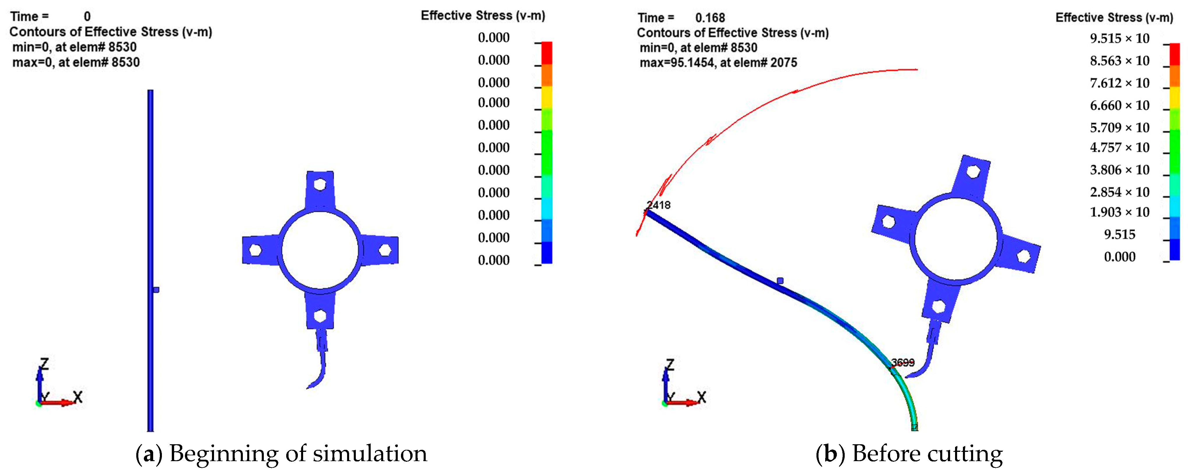
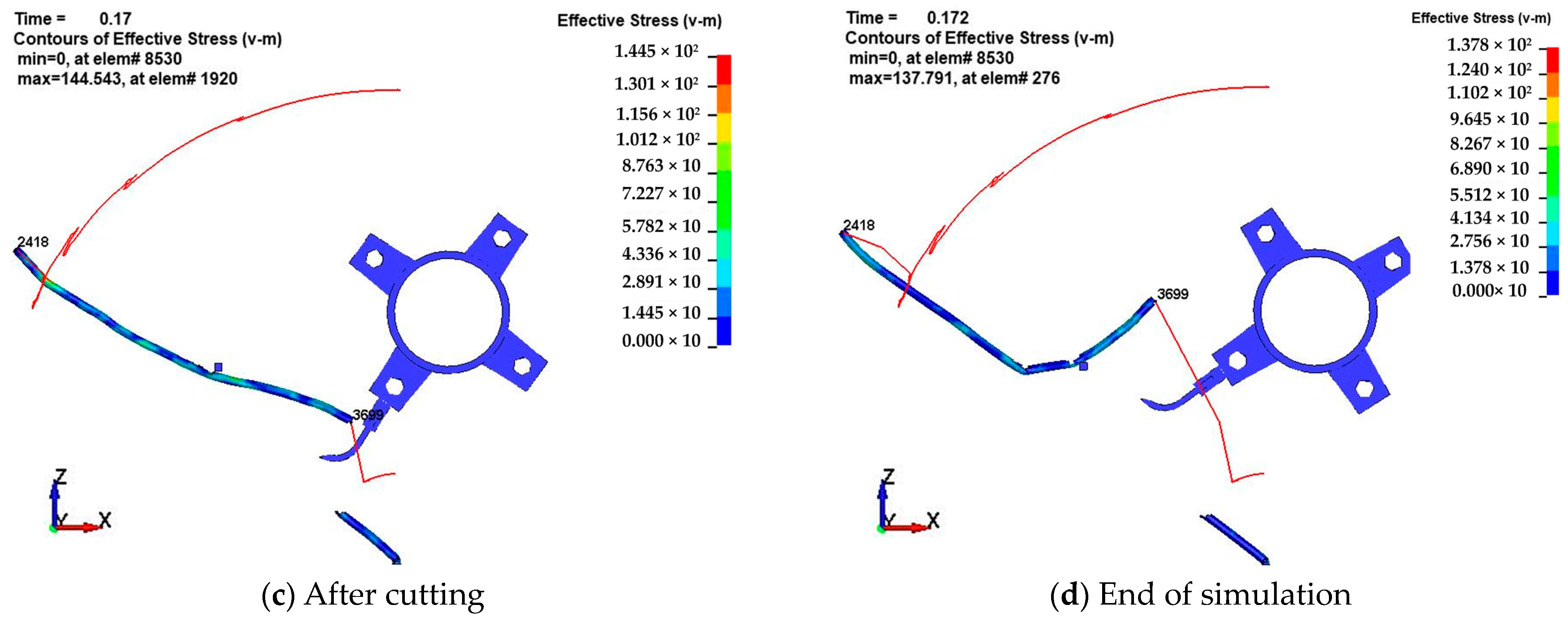
5.1. Simulation Results for Cutting
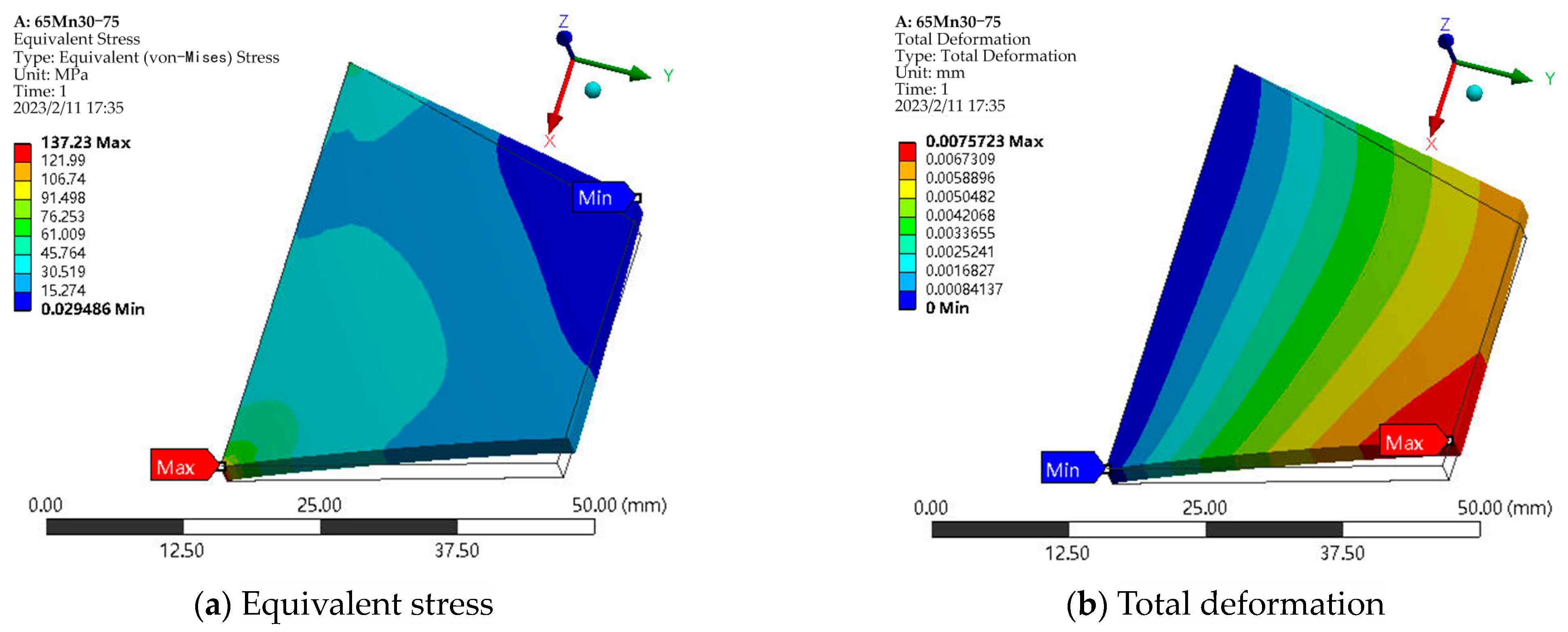
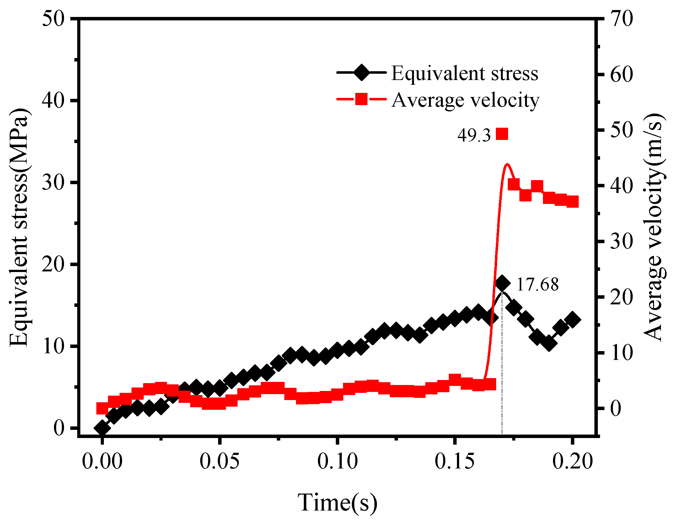
5.1.1. Equivalent Stress and Velocity Variations
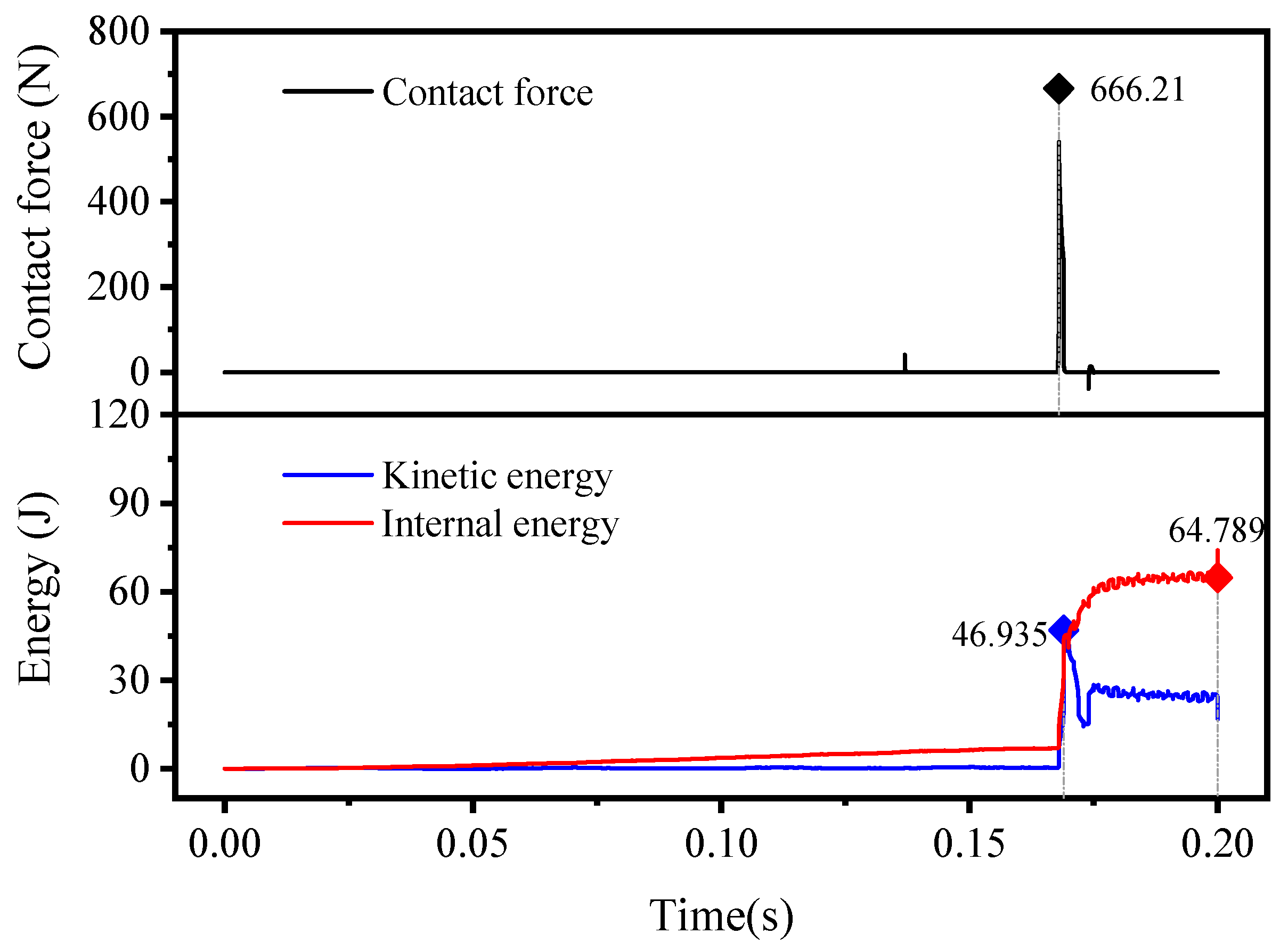
5.1.2. Contact Force and Energy Variations
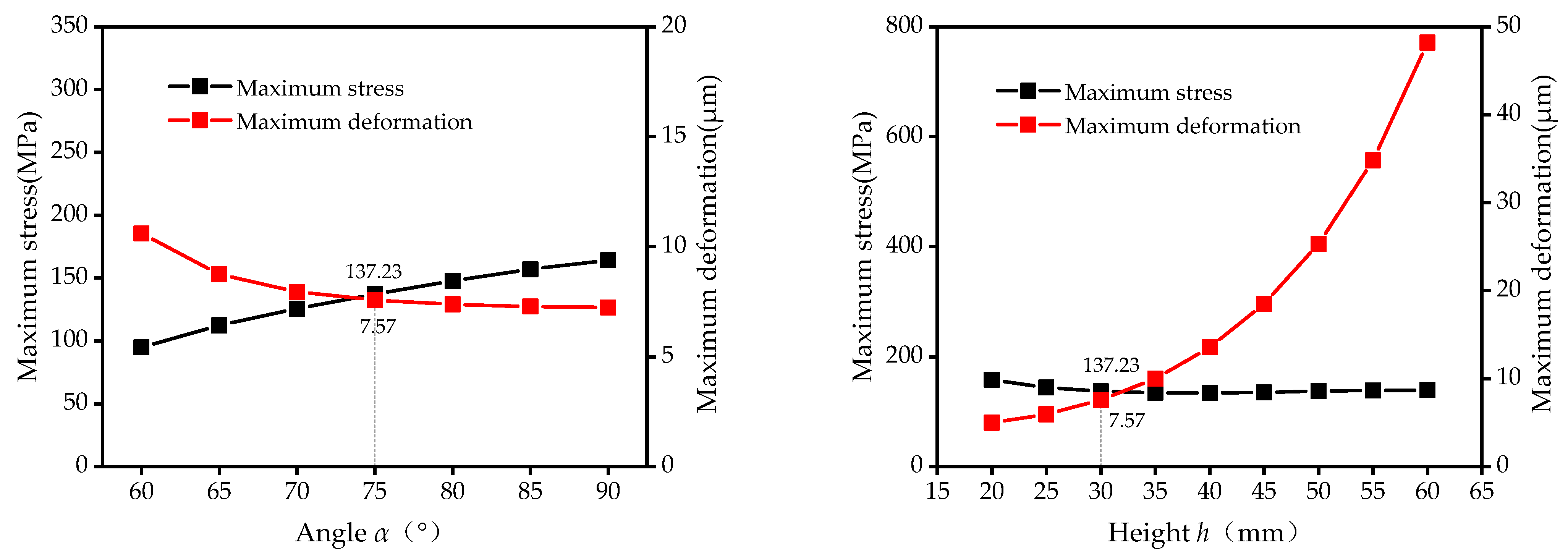
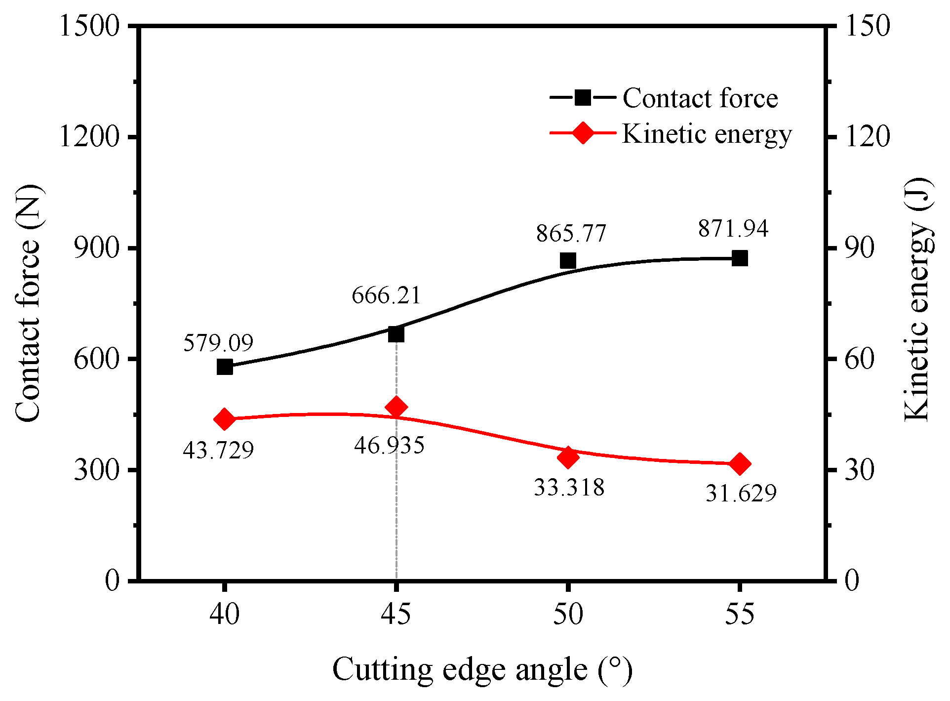
5.1.3. Effect of the Cutting Edge Angle (γ) on Stalk Cutting
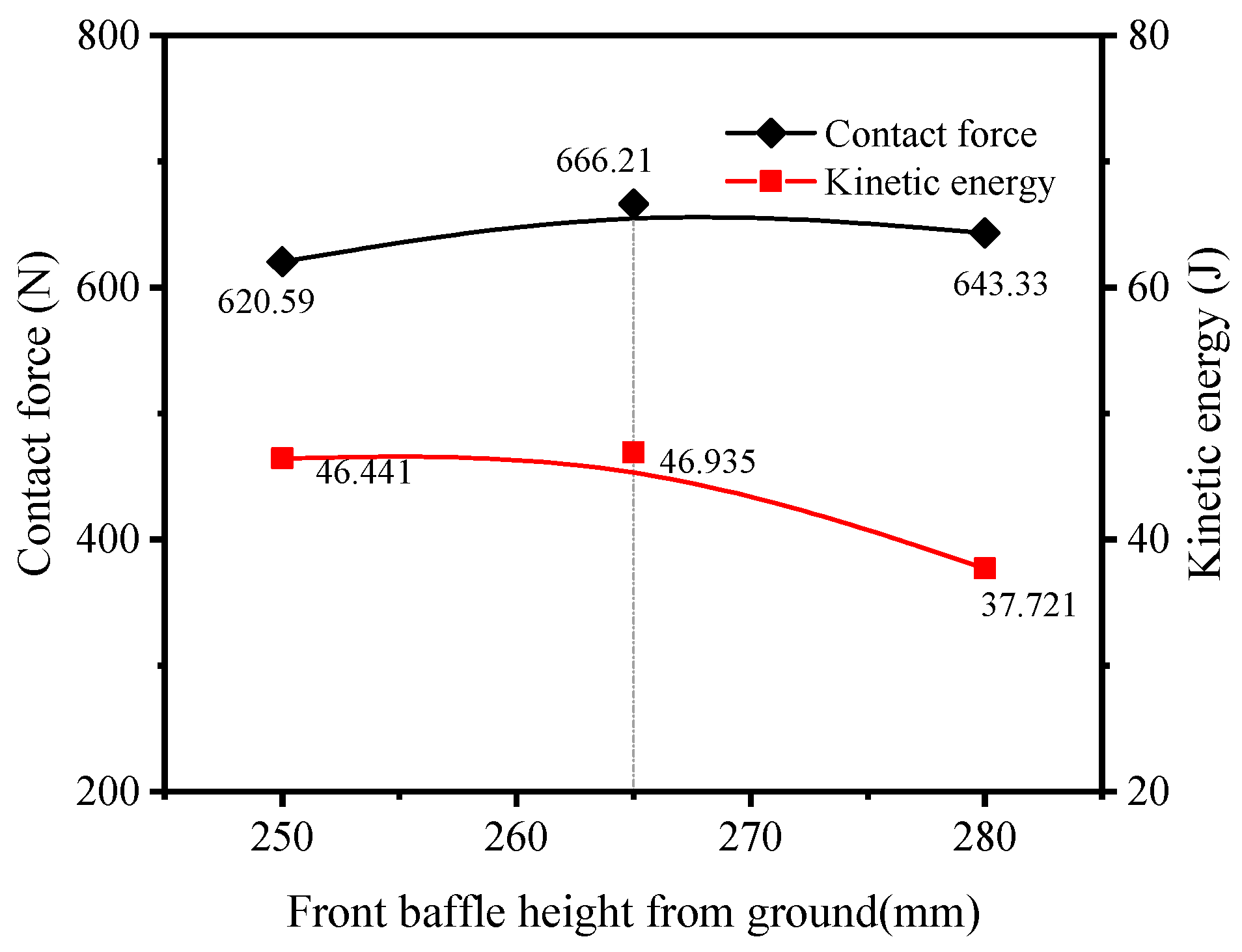
5.1.4. Effect of the Front Baffle Height (h1) on Stalk Cutting
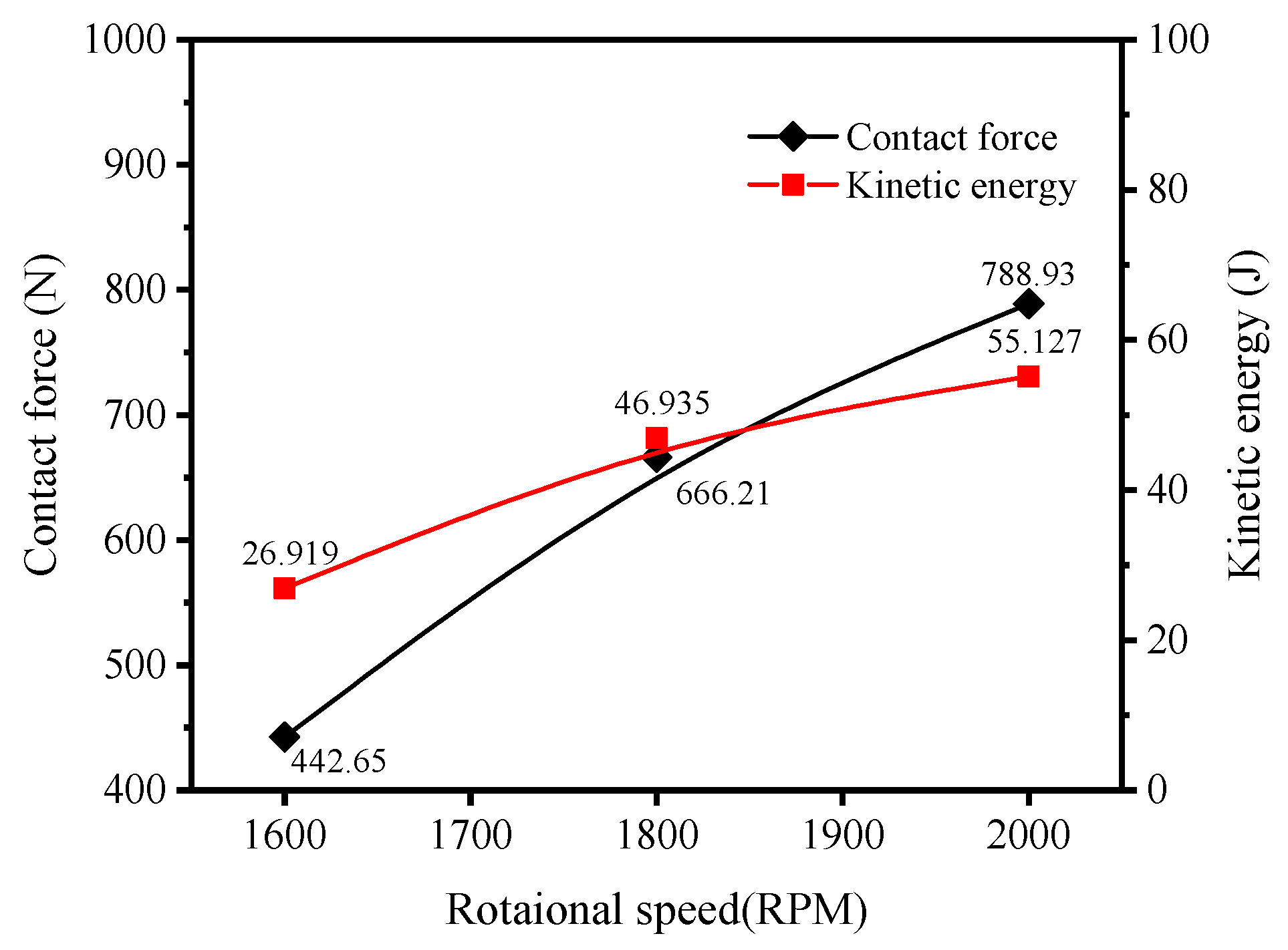
5.1.5. Effect of the Cutter’s Rotational Speed n on Stalk Cutting
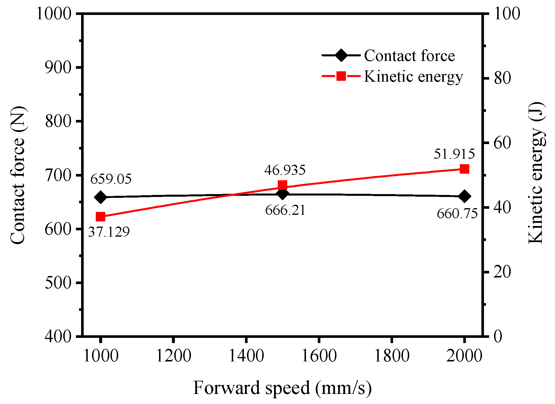
5.1.6. Effects of the Machine’s Forward Speed v0 on Stalk Cutting
5.2. Simulation Results for Crushing
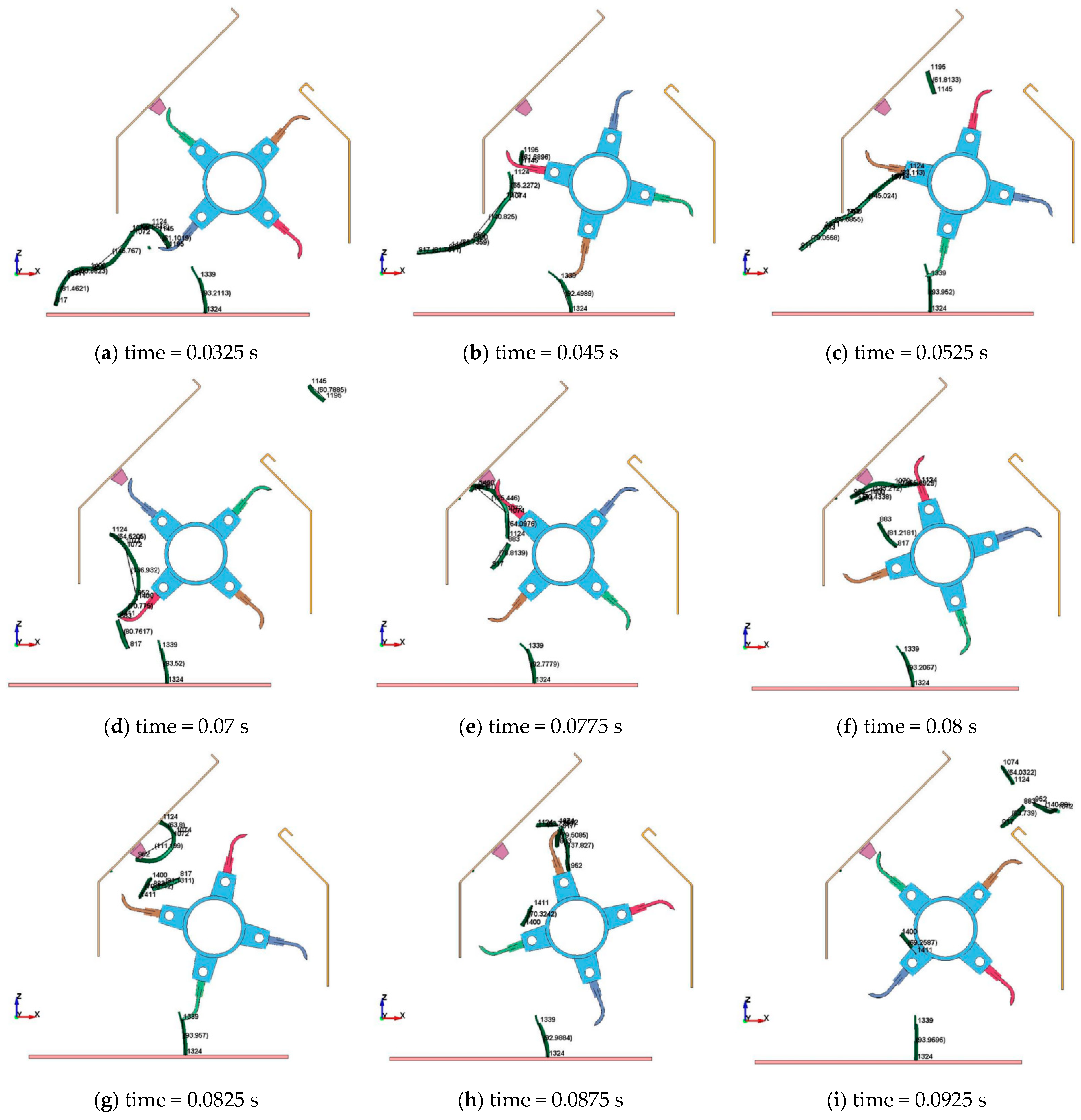
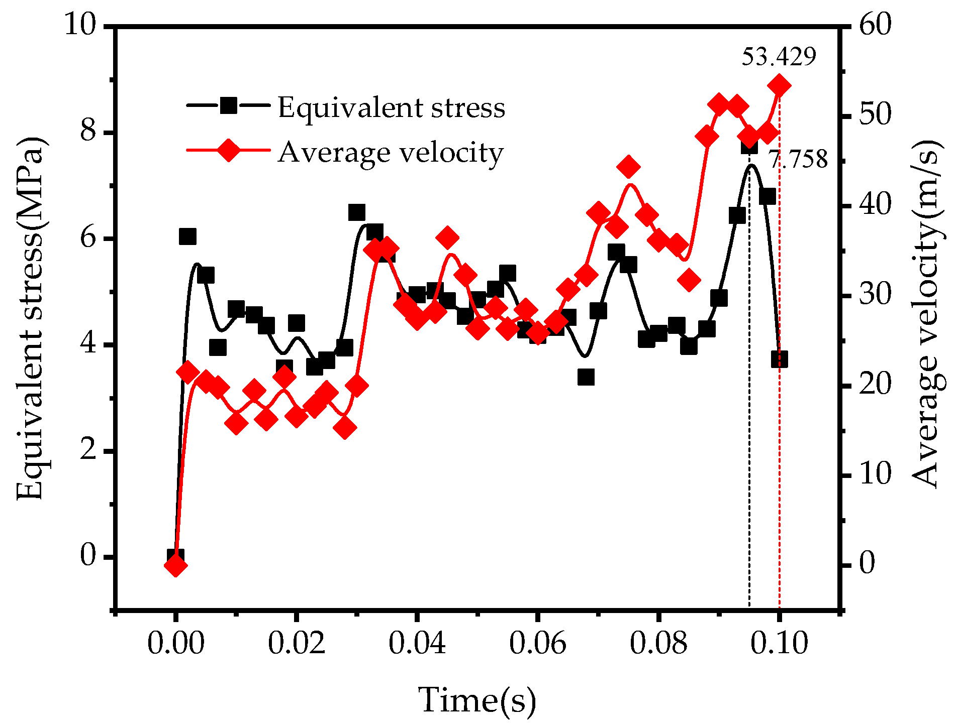
5.2.1. Equivalent Stress and Velocity Variations
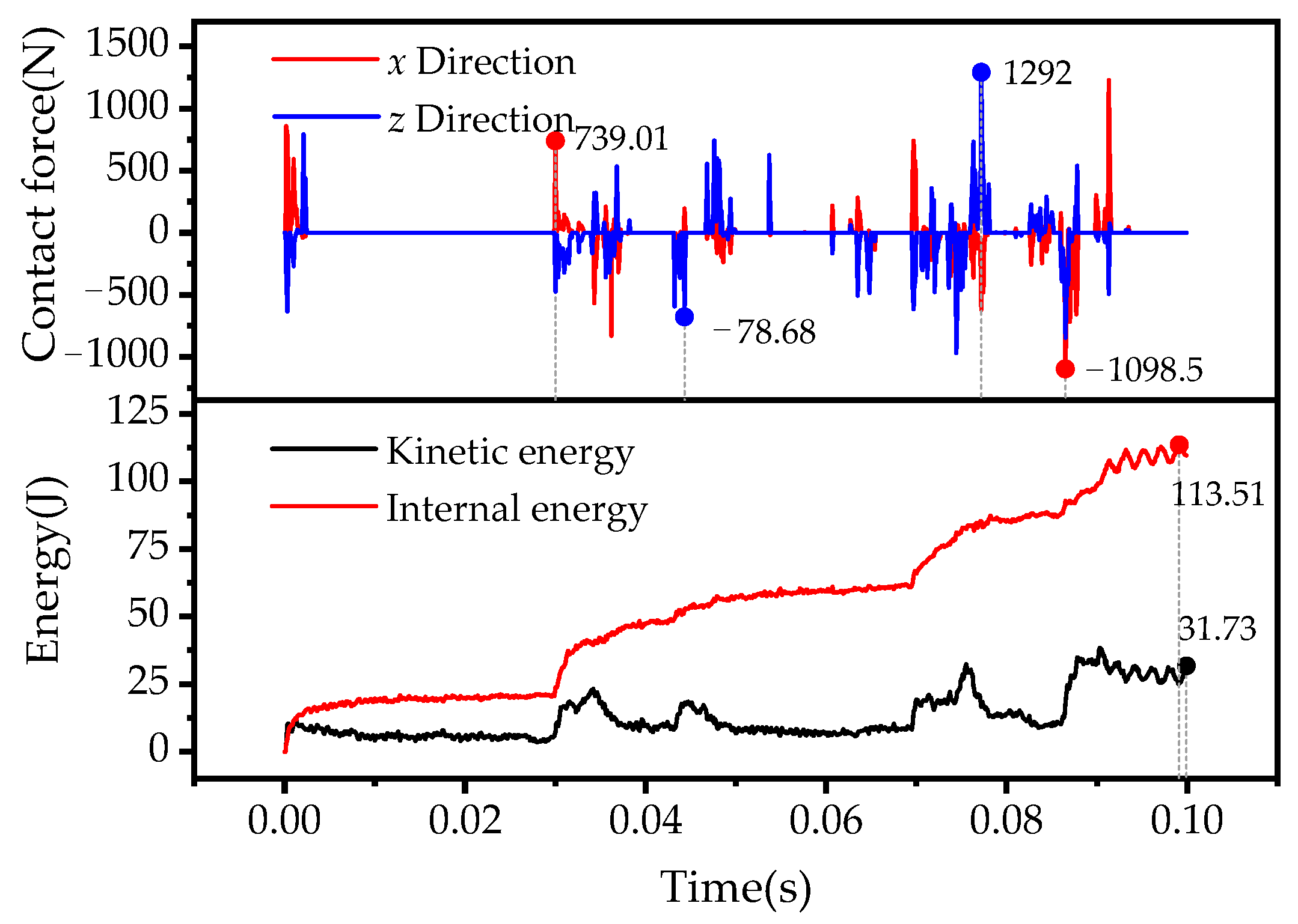
5.2.2. Contact Force and Energy Variations
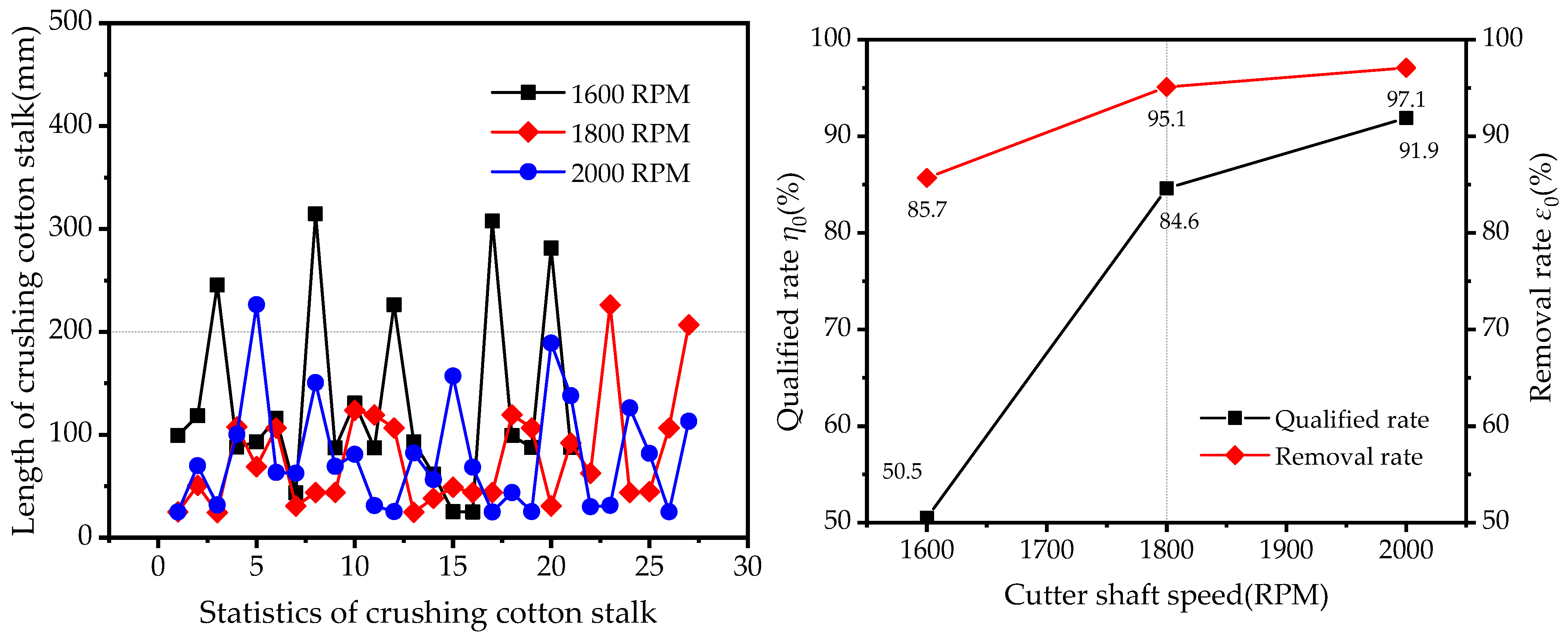
5.2.3. Effect of the Cutter’s Rotational Speed on Straw Smashing
6. Field Experiment
6.1. Test Conditions
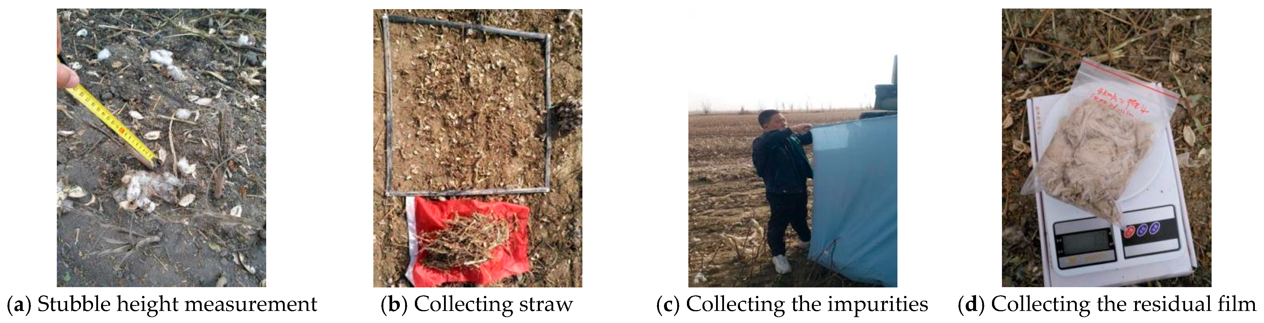
6.2. Test Indexes and Method
6.2.1. Stubble Height Y1
6.2.2. Rate of Qualified Straw Crushing Y2
6.2.3. Film-Surface-Impurity Clearance Rate Y3
6.2.4. Film Content Y4
7. Results and Discussion
7.1. Experimental Results
7.2. Discussion
8. Conclusions
Author Contributions
Funding
Institutional Review Board Statement
Informed Consent Statement
Data Availability Statement
Conflicts of Interest
References
- Gao, H.; Yan, C.; Liu, Q.; Ding, W.; Chen, B.; Li, Z. Effects of plastic mulching and plastic residue on agricultural production: A meta-analysis. Sci. Total Environ. 2019, 651, 484–492. [Google Scholar] [CrossRef] [PubMed]
- Chen, B.; Cui, J.; Dong, W.; Yan, C. Effects of Biodegradable Plastic Film on Carbon Footprint of Crop Production. Agriculture 2023, 13, 816. [Google Scholar] [CrossRef]
- Wang, P.; Chen, X.; Wen, H. Research and Experiment on the Removal Mechanism of Light Impurities of the Residual Mulch Film Recovery Machine. Agriculture 2022, 12, 775. [Google Scholar] [CrossRef]
- Xie, C.; Kang, J.; Peng, Q.; Wang, X.; Chen, Y.; Zhang, C.; Zhang, N. Optimization of Screen-Hole-Clearing Devices for Mechanized Residual Film–Impurity Separation. Appl. Sci. 2022, 12, 11658. [Google Scholar] [CrossRef]
- Peng, Q.; Li, K.; Wang, X.; Zhang, G.; Kang, J. Design and Test of Stripping and Impurity Removal Device for Spring-Tooth Residual Plastic Film Collector. Agriculture 2023, 13, 42. [Google Scholar] [CrossRef]
- Cao, S.; Xie, J.; Wang, H.; Yang, Y.; Zhang, Y.; Zhou, J.; Wu, S. Design and Operating Parameters Optimization of the Hook-and-Tooth Chain Rail Type Residual Film Picking Device. Agriculture 2022, 12, 1717. [Google Scholar] [CrossRef]
- Shi, X.; Niu, C.; Wang, X.; Zhang, H.; Yang, H. Design of roller sieve waste plastic film and trash winnowing machine. Trans. Chin. Soc. Agric. Eng. 2017, 33, 19–26. [Google Scholar]
- Li, J. Study on the Water-Separating Device of Residual Film Mixture Collected by Machine. Master’s Thesis, Shihezi University, Shihezi, China, 2018. [Google Scholar]
- Tang, J.; Li, X.; Zhang, G.; Lu, W.; Ni, S.; Sun, Z.; Li, H.; Zhao, C.; Zhang, H.; Zhang, Q.; et al. An ANSYS/LS-DYNA Simulation and Experimental Study of Sectional Hob Type Laver Harvesting Device. Agriculture 2023, 13, 361. [Google Scholar] [CrossRef]
- Duan, Y.; Yuan, D.; Wu, J.; Deng, X.; Wu, B.; Sun, Z. Effect of the Geometric Configuration of the Disc Cutter on the Cutting Behaviour in Tunneling. Appl. Sci. 2023, 13, 72. [Google Scholar] [CrossRef]
- Cao, W.; Sun, W.; Niu, C.; Jiao, J.; Chen, B. Combed Safflower Picking Device Based on ANSYS/LS-DYNA. Trans. Chin. Soc. Agric. Mach. 2018, 49, 123–131. [Google Scholar]
- Sun, J.; Xing, K.; Yang, Z.; Duan, J. Simulation and experimental research on fruit branch pruning process based on ANSYS/LS-DYNA. J. South China Agric. Univ. 2022, 43, 113–124. [Google Scholar]
- Dun, G.Q.; Yang, Y.Z.; Li, H.S. Working parameters optimization of soybean serration rotarycutter by ANSYS/LS-DYNA. J. Henan Agric. Univ. 2019, 53, 739–744. [Google Scholar]
- Shi, J.; Chen, F.; Guo, J.; Wang, X. Design and experimental research of the field straw chopper with throwing cotton-stalk. Trans. Chin. Soc. Agric. Eng. 2006, 22, 68–72. [Google Scholar]
- Zhang, Z.; He, J.; Li, H.; Wang, Q.; Ju, J.; Yan, X. Design and Experiment on Straw Chopper Cum Spreader with Adjustable Spreading Device. Trans. Chin. Soc. Agric. Mach. 2017, 48, 76–87. [Google Scholar]
- Qin, K.; Cao, C.; Liao, Y.; Wang, C.Q.; Fang, L.F.; Ge, J. Design and optimization of crushing and throwing device for straw returning to field and fertilizing hill-seeding machine. Trans. Chin. Soc. Agric. Eng. 2020, 36, 1–10. [Google Scholar]
- Zhang, X.; Wang, Z.; Li, Y.; Liang, D. Design and experiment of sliding-cutting and anti-twining returning device for banana straw. Trans. Chin. Soc. Agric. Eng. 2018, 34, 26–34. [Google Scholar]
- Chinese Academy of Agricultural Mechanization Science. Agricultural Machinery Design Manual; Agricultural Science and Technology Press: Beijing, China, 2007; Volume 1. [Google Scholar]
- Yu, Y.; Chen, X.; Wen, H. Development and experiment of straw chopping and plastic film strip-collection combined machine. Trans. Chin. Soc. Agric. Eng. 2016, 32, 1–8. [Google Scholar]
- Ding, L. Design and Experimental Study on Saw Type Cotton Stalk Cutting Test Bench. Master’s Thesis, Shihezi University, Shihezi, China, 2015. [Google Scholar]
- Zheng, Z.; He, J.; Li, H.; Diao, P.; Wang, Q.; Zhang, C. Design and Experiment of Straw-chopping Device with Chopping and Fixed Knife Supported Slide Cutting. Trans. Chin. Soc. Agric. Mach. 2016, 47, 108–116. [Google Scholar]
- Pu, L.; Ji, M. Mechanical Design, 8th ed.; Higher Education Press: Beijing, China, 2006; pp. 120–126. [Google Scholar]
- Jiménez-Armendáriz, J.; Jimenez-Martinez, M.; Varela-Soriano, J.; Santana-Diaz, A.; Perez-Santiago, R. Energy Dissipation Enhancement of Thin-Walled 6063 T5 Aluminium Tubes by Combining a Triggering Mechanism and Heat Treatment. Metals 2023, 13, 922. [Google Scholar] [CrossRef]
- Tian, X.; Zhao, Y.; Chen, X.; Yan, L.; Wen, H.; Gou, H.; Ji, C. Development of 4JSM-2000A type combined operation machine for cotton stalk chopping and residual plastic film collecting. Trans. Chin. Soc. Agric. Eng. 2018, 34, 25–35. [Google Scholar]
- Shi, N. Peeling Method of Cotton Stalk and Development of Rubbing Peeling Machine. Doctor’s Thesis, Northwest A & F University, Yangling, China, 2014. [Google Scholar]
- Zhao, W.; Xie, J.; Wang, Z.; Gao, Q.; Chen, M. Investigation of mechanical properties of cotton stalk based on multi-component analyses. Int. Agrophys. 2022, 36, 257–267. [Google Scholar] [CrossRef]


| Ex | Ey | Ez | Gxy | Gxz | Gyz | uxy | uxz | uyz |
|---|---|---|---|---|---|---|---|---|
| MPa | ||||||||
| 91.04 | 91.04 | 3181.79 | 28.45 | 180.88 | 180.88 | 0.6 | 0.025 | 0.025 |
Disclaimer/Publisher’s Note: The statements, opinions and data contained in all publications are solely those of the individual author(s) and contributor(s) and not of MDPI and/or the editor(s). MDPI and/or the editor(s) disclaim responsibility for any injury to people or property resulting from any ideas, methods, instructions or products referred to in the content. |
© 2023 by the authors. Licensee MDPI, Basel, Switzerland. This article is an open access article distributed under the terms and conditions of the Creative Commons Attribution (CC BY) license (https://creativecommons.org/licenses/by/4.0/).
Share and Cite
Wang, P.; Chen, X.; Wen, H. Simulation Research on Cotton Stalk Cutting and Crushing Based on ANSYS/LS-DYNA and Field Experiments. Agriculture 2023, 13, 1268. https://doi.org/10.3390/agriculture13061268
Wang P, Chen X, Wen H. Simulation Research on Cotton Stalk Cutting and Crushing Based on ANSYS/LS-DYNA and Field Experiments. Agriculture. 2023; 13(6):1268. https://doi.org/10.3390/agriculture13061268
Chicago/Turabian StyleWang, Peng, Xuegeng Chen, and Haojun Wen. 2023. "Simulation Research on Cotton Stalk Cutting and Crushing Based on ANSYS/LS-DYNA and Field Experiments" Agriculture 13, no. 6: 1268. https://doi.org/10.3390/agriculture13061268