Article

Development Results of a Cross-Platform Positioning System for a Robotics Feed System at a Dairy Cattle Complex

by
Dmitriy Yu. Pavkin
1,
Evgeniy A. Nikitin
1,*,
Denis V. Shilin
1,
Mikhail V. Belyakov
1,
Ilya A. Golyshkov
1,
Stanislav Mikhailichenko
1 and
Ekaterina Chepurina
2
1
Federal Scientific Agroengineering Center VIM, 109428 Moscow, Russia
2
Department of Engineering and Computer Graphics, Federal State Budget Educational Institution of Higher Education, Russian State Agrarian University—Moscow Timiryazev Agricultural Academy (RSAU—MTAA), 127550 Moscow, Russia
*
Author to whom correspondence should be addressed.
Agriculture 2023, 13(7), 1422; https://doi.org/10.3390/agriculture13071422
Submission received: 19 June 2023 / Revised: 14 July 2023 / Accepted: 15 July 2023 / Published: 19 July 2023
(This article belongs to the Special Issue Recent Advancements in Precision Livestock Farming)

Abstract

:
Practical experience demonstrates that the development of agriculture is following the path of automating and robotizing operational processes. The operation of feed pushing in the feeding alley is an integral part of the feeding process and significantly impacts dairy cattle productivity. The aim of this research is to develop an algorithm for automatic positioning and a mobile remote-control system for a wheeled robot on a dairy farm. The kinematic and dynamic motion characteristics of the wheeled robot were obtained using software that allows simulation of physical processes in an artificial environment. The mobile application was developed using Swift tools, with the preliminary visualization of interfaces and graphic design. The system uses technical vision based on RGB cameras and programmed color filters and is responsible for the automatic positioning of the feed-pusher robot. This system made it possible to eliminate the inductive sensors from the system and suspend the labor effort required for assembling the contour wire of the feed alley. By assessing the interaction between the mobile app and the feed pusher via the base station connected to the Internet and located on the farm, the efficiency and accuracy of the feedback was measured. Furthermore, remote changes in the operating regime of the robot (start date) were proven to be achievable, and the productiveness of the food supplement dispenser also became manageable.

1. Introduction

Milk and food products made from it are important elements in the human diet. As is well known, the volume of dairy products consumed has grown significantly over the past decades. In 2017, 497 million metric tons of cow’s milk were produced worldwide; by 2022, this figure had grown to about 534 million metric tons [1].
In many ways, this contributed to the implementation of large engineering projects, with milking herds of more than 1000 heads in countries such as India, the USA, Pakistan, Russia, Brazil and China [1,2].
Automation and digitalization of technological processes is an integral part of the implementation of such projects, which indicates the interaction between livestock equipment manufacturers and companies from the IT sector; it is an effective interaction that facilitates the farmer’s work and stabilizes deductions to a technology company, because digital products are used on the farm every day [3].
To date, the market for technological solutions offers a variety of software products that allow dairy cattle breeding, the control of productive indicators and timely identification and notification of the hunting of animals and upcoming calving—these and other software functions are an effective means of making managerial decisions. In addition to software, the level of interest in the means of robotization of technological processes (milking robots and feed distribution robots) has increased from small farms over the past 10 years [4].
The analysis of the current situation in dairy production indicates that effective development in the field may be guaranteed only at the new and novel technological levels [5].
Practical experience demonstrates that the development of agriculture is following the path of the automatization and robotization of operation processes. This is due to the requirements concerning the increase in production performance as well as the problems connected with the shortage of human resources [6,7,8].
For example, for a farmer, the use of robots, in particular milking robots, is not only a relief of labor but also an opportunity to improve the quality of animal care and the quality of the products received. In particular, in [9], it is shown through voluntary visits to the milking unit that the use of milking robots for walking animals significantly reduces the stress level of animals.
Such novelties allow for the better realization of the cattle’s genetic potential, the more rational use of forage and better use of energetic, financial and labor resources and major funds, as well as for obtaining products of higher quality and ecological purity [10,11,12,13].
One of the key examples of the partial robotization of the feeding process is the use of forage robots. Such machines are manufactured in Europe, for instance, by Lely, Delaval, Wasserbauer and GEA.
The obvious advantage of using robotics in the feeding process is the provision of cyclic feed distribution, which increases the level of feed consumption. It also enhances the frequency of animal visits to the feeding alley. This has been confirmed through the analysis of feeding processes on farms. Studies revealed that a feed distribution frequency of three or more times a day increases the animals’ interest and the number of visits to the feed alley, leading to higher daily feed consumption levels by the animals [14,15,16,17].
In their research, Miller-Kushon et al. have repeatedly stated that cattle tend to sort the components of the feed mixture in favor of energetically valuable compound feeds with high taste qualities, whereas the animals try to neglect bulk feeds such as silage and hay, which are the main sources of fiber [18].
The problem of selective feed consumption can be solved by using wheeled robotic technical means that will carry out the dosing of concentrated feed additives in proportion to the amount of feed remaining in the feed alley [19,20,21]. A fundamental problem in robotics is path planning, as the robot interacts with the feed and encounters mechanical resistance while operating on the feed alley. Some manufacturers employ inductive sensors and fixed metal tags placed at regular intervals to ensure the robot maintains its trajectory [22,23,24].
In existing works for dairy cattle complexes, the mobile base moves along a metal belt, along which the mobile robot is oriented by means of inductive sensors. If the robot deviates from the metal belt during its operation, telemetry signals from the inductive sensors recognize the direction of its deviation from the trajectory and send a signal to the robot controller to return it to the correct path [25,26,27].
However, due to the chaotic placement of feed in the feed alley (including feed spills caused by the actions of dairy animals), there is a possibility that the metal belt may not be detected by the inductive sensors when the robot returns to the trajectory, which negatively affects the productivity and energy efficiency of the robot. The novel solution is an intelligent algorithm that performs a preliminary semantic segmentation of the image from a stereovision camera in order to detect the feed and the frames of the dairy animal stall and provides additional orientation for the mobile base in case of emergency situations or failure to detect the trajectory due to contamination of the metal belt [28,29,30].
When solving the problem of the selective consumption of concentrated feed by cattle using a wheeled robot with a hopper dispenser, it is also necessary to estimate the volume of the feed located in the feed alley. To achieve this, we hypothesize that the vision system can construct three-dimensional images and take into account the volume of feed [31,32,33].
The present study describes the development of cross-platform system positioning; the system has been tested using a feed-pusher robot with a screw working body and a dispenser for the periodic application of high-density compound feeds or mineral additives during the maintenance of the feed alley.
In our study, we show that the developed robot can serve as a tool for performing cyclic manipulations in the feed alley, providing increased interest for the animals to feed and multiple doses of energy feed or mineral additives during each feeding cycle, which could prevent cases of increased feed consumption. A custom remote-control application on the IOS platform was developed for the robot.
The installed feed additive dispenser, which has an automatic performance monitoring system, can provide individual feeding modes for each group of animals. Our robot provides the cyclic introduction of concentrates and increases the level of consumption of the main feed.

2. Materials and Methods

Matlab Simulink (Math Works) software with the Simscape and Mechanics packages was used to model the motion process of the wheeled robot and visualize the movement trajectory changes and dependencies of the kinematic and dynamic motion parameters.
At the designing stage of the pusher robot control system, the expected trajectory of the robot motion was modeled. To ensure autonomous positioning of the designed robot, its motion trajectory should be elementary; in other words, it moves in a straight line with minor deviations depending on the amount of feed residue on the feed alley floor (Figure 1). To determine the amount of feed residue in the vision system, an algorithm was developed. This algorithm calculates the range of the spread from the fence and the volume of the feed by means of an RGB stereo pair.
At the same time, the variation of the trajectory of the wheeled robot relative to the feed occurs through the technical vision system (Figure 2).
This system functions by obtaining binarized images.
A machine learning algorithm allows the breaking down of the RGB images into binary ones, with the area of interest highlighted in gray being the animal feed mixture. The resulting contrast enables the assessment of the spread of the feed mixture in the binary image, providing a qualitative evaluation of the distance that it is spread on the feeding alley. Automatic positioning is achieved by determining the area and subsequently building the trajectory of the robotic device relative to the edge.
To describe binarized images of size [X,Y], we use the matrix p(i,j) to represent each pixel, with its coordinates (i,j) in the image given by 0 ≤ i < N and 0 ≤ j < M. Pixel p(i,j) has four adjacent pixels, namely p(i − 1,j), p(i,j − 1), p(i + 1,j) and p(i,j + 1) and together with p(i − 1,j − 1), p(i + 1,j − 1), p(i − 1,j + 1) and p(i + 1,j + 1) they form the eight neighboring pixels of p(i,j). Two points of an object, denoted by “s” and “t”, are considered four connected (eight connected) if a trajectory exists consisting of the object’s points a 1 , a 2 , …, a n , such that a 1 = s and a n = t and for all 1 k n 1 and a k and a k + 1 are four adjacent (eight adjacent) to each other. A four-connected (eight-connected) component in a binary image is defined as the point cloud of an object, such that any two pixels in the set are four connected (eight connected) and the associated component is the desired object (compound feed). The area of object O , denoted as S O , is defined as the number of pixels in object O and can be calculated using the formula:
S O = p x , y | p ( x , y ) O
An area with eight connections has a denser concentration of feed mixture on the feeding alley floor, whereas an area with four connections has a lower amount of mixture, allowing for the recognition of the extreme edge that can be used for subsequent orientation of the robot during movement. To detect the boundary of the feed spread, the image is divided into multiple parts and the area of the regions of interest (gray) is summed up to determine the total spot area.
K = 1 , S i S O L ,   0 ,   S i S O > L .
S i is the average area for the i-th binarized image;
K is the indicator for the area of interest (1 for the feed mixture, 0 for the non-interesting area of the farm), whereas L is the center of mass of the robot (distance from the fence of the feeding alley).
The automatic positioning system algorithm processes images of the same size, so its complexity is constant. Thus, for our algorithm, g(n) = n.
For image processing, we used the Image Processing Toolbox pocket and, in particular, the Color Threshold application and the Image RegionAnalyzer application.
Next, we formed a mathematical justification for the dependencies of the parameters of the movement of wheeled robots in the feed alley on the farm.

3. Results

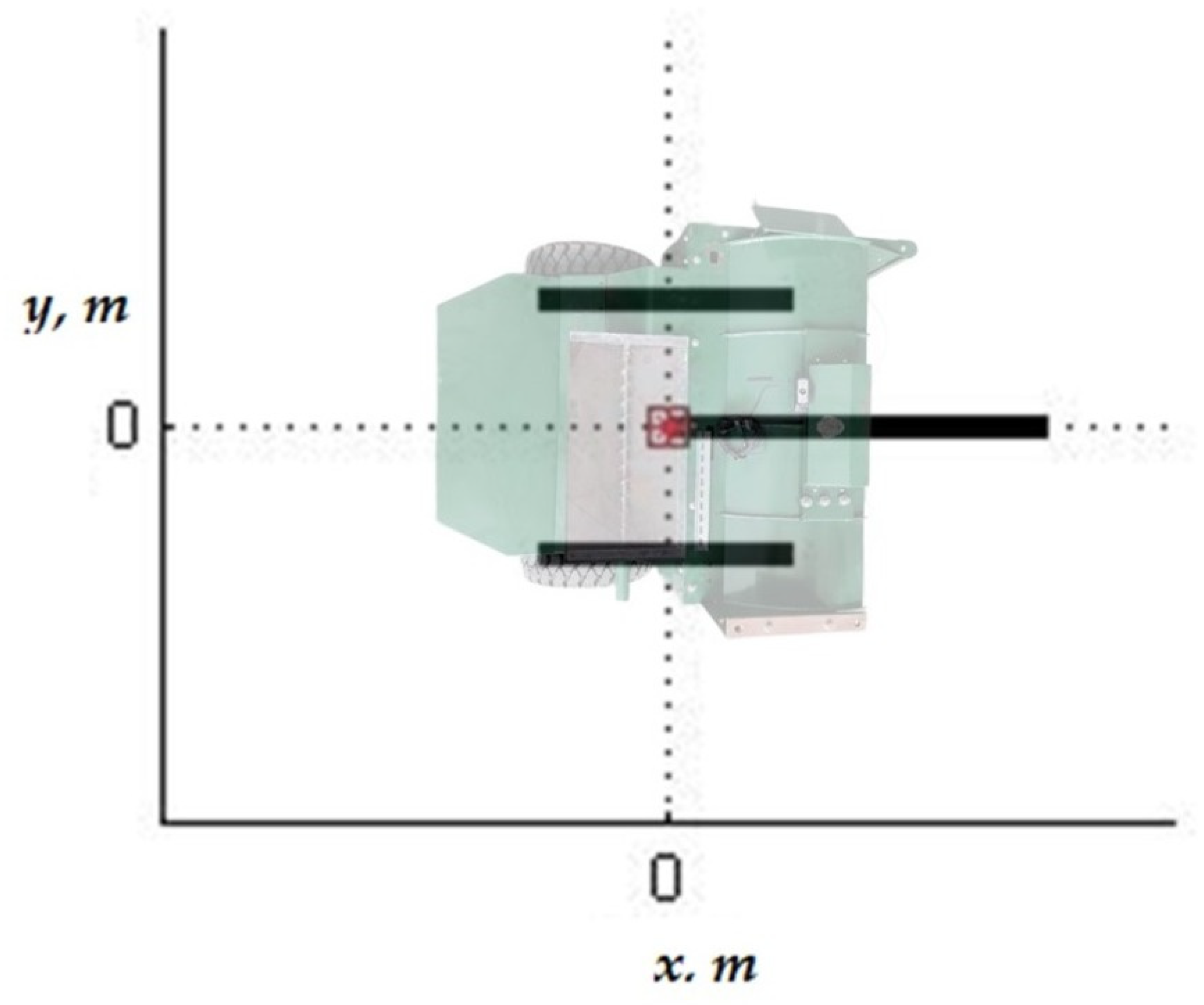
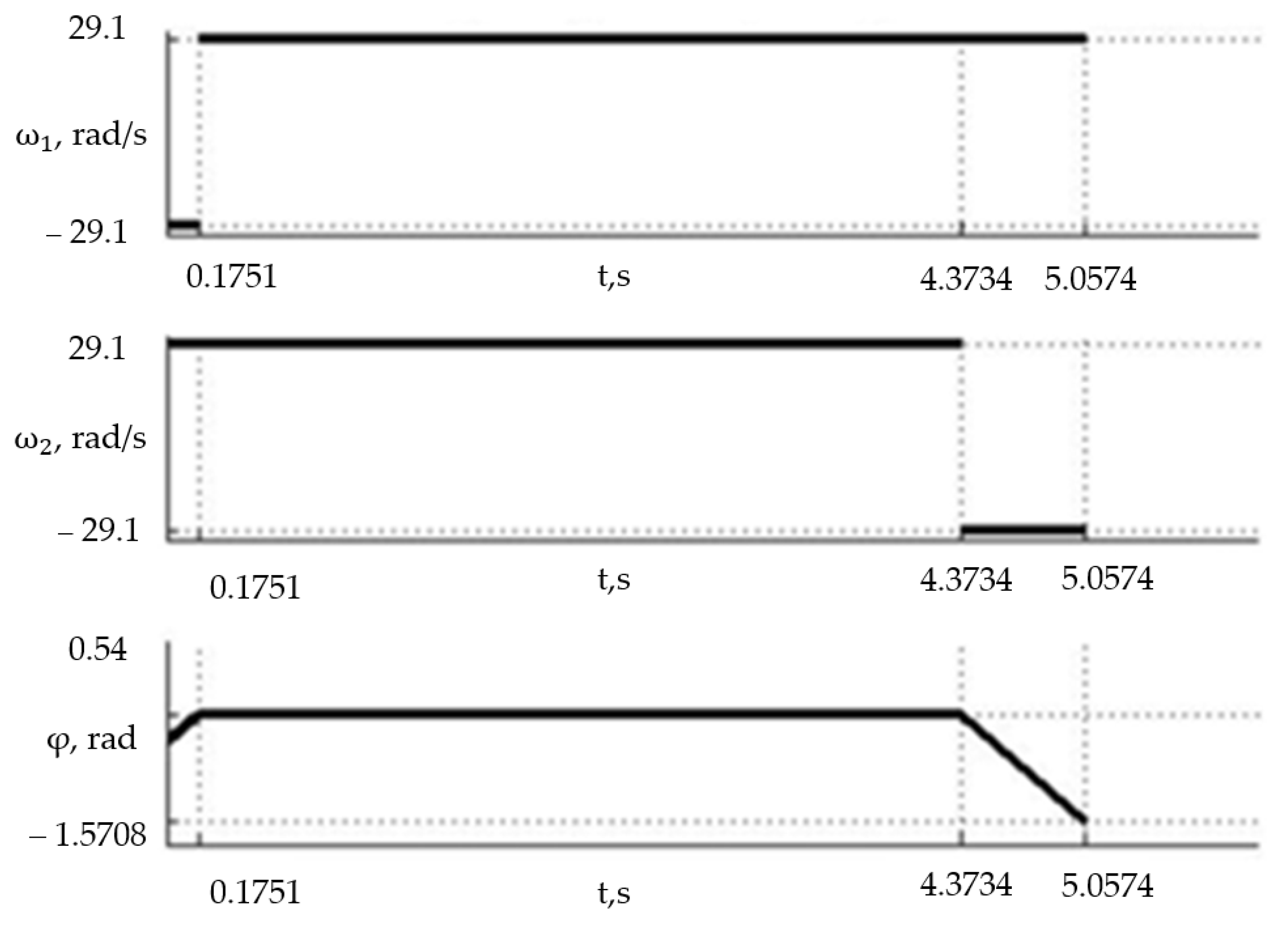
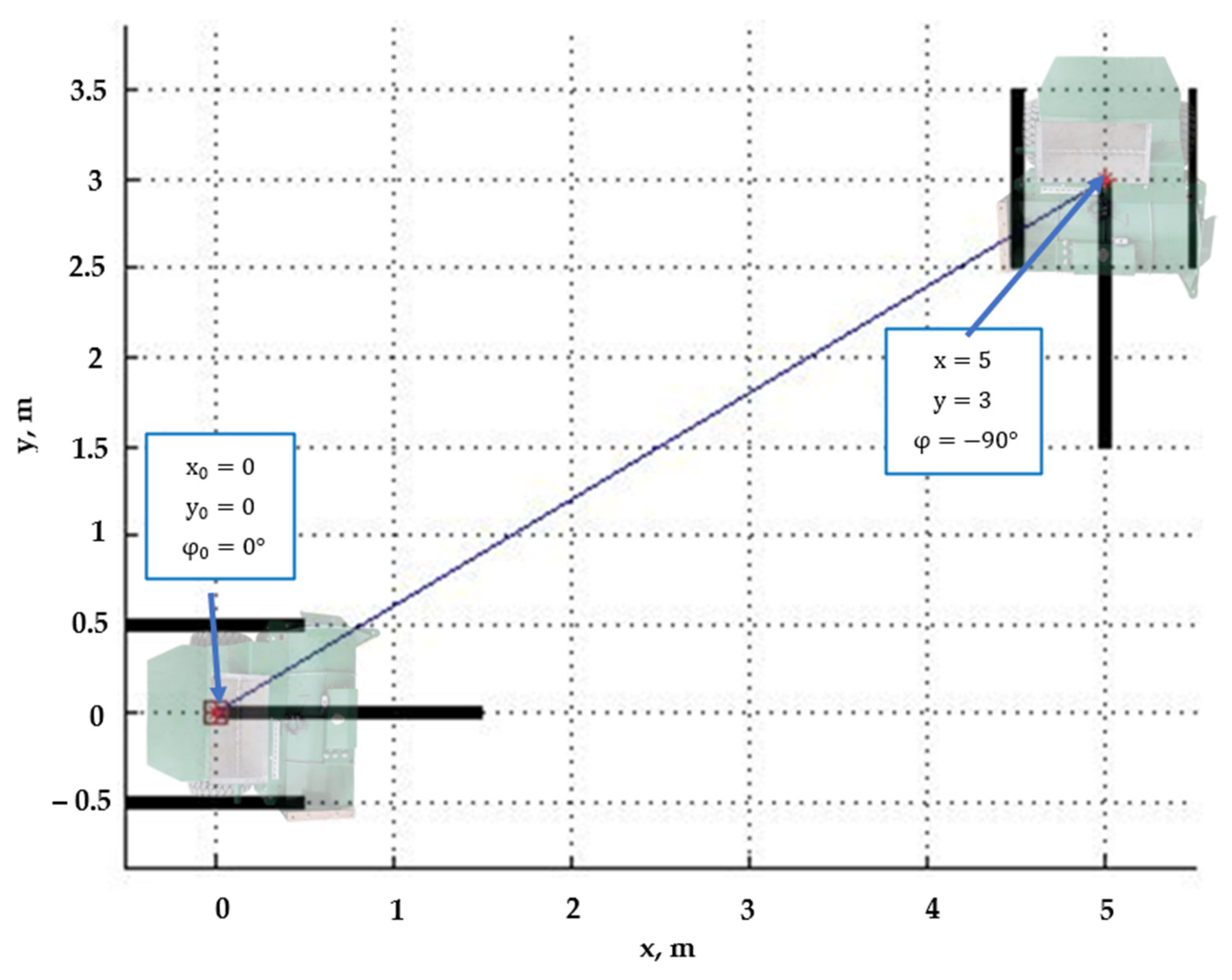
3.1. Kinematic Calculation of Robot Movement

When calculating the kinematics of a robot, it is necessary to establish the relationship between the size of the robot, the speed of each element and the robot’s coordinates. The main equations used in kinematics calculations are:
Changes in coordinates along the “x” axis
x i = ϑ O i · t i · cos φ i
When moving along the “y” axis
y i = ϑ O i · t i · sin φ i  
The velocity characteristics of the robot’s movement, taking into account the radius of the driving wheel, are
ϑ O = r · ω
The nature of the change in the trajectory of the center of mass movement, taking into account the radius of the drive wheel, is
ϑ O = R · ω 1 + ω 2 2  
x i ,   y i —the increments in the coordinates along the x and y axes, respectively, on the i-th path segment;
ϑ O i —linear velocity of the robot’s center of mass on the i-th path segment;
t i —time of movement on the i-th path segment;
r —radius of the robot’s drive wheels;
R —radius of the trajectory of the robot’s center of mass movement along a circle.
The angular velocity of the wheel, equal to 4.6296 rad/s, corresponds to the linear velocity of the hypothetical center of mass equal to 5 m/s at a trajectory radius of 0.45 m (half the axis of the drive wheels or half the width of the robot). A complete rotation of the robot around itself takes 2.0358 s.

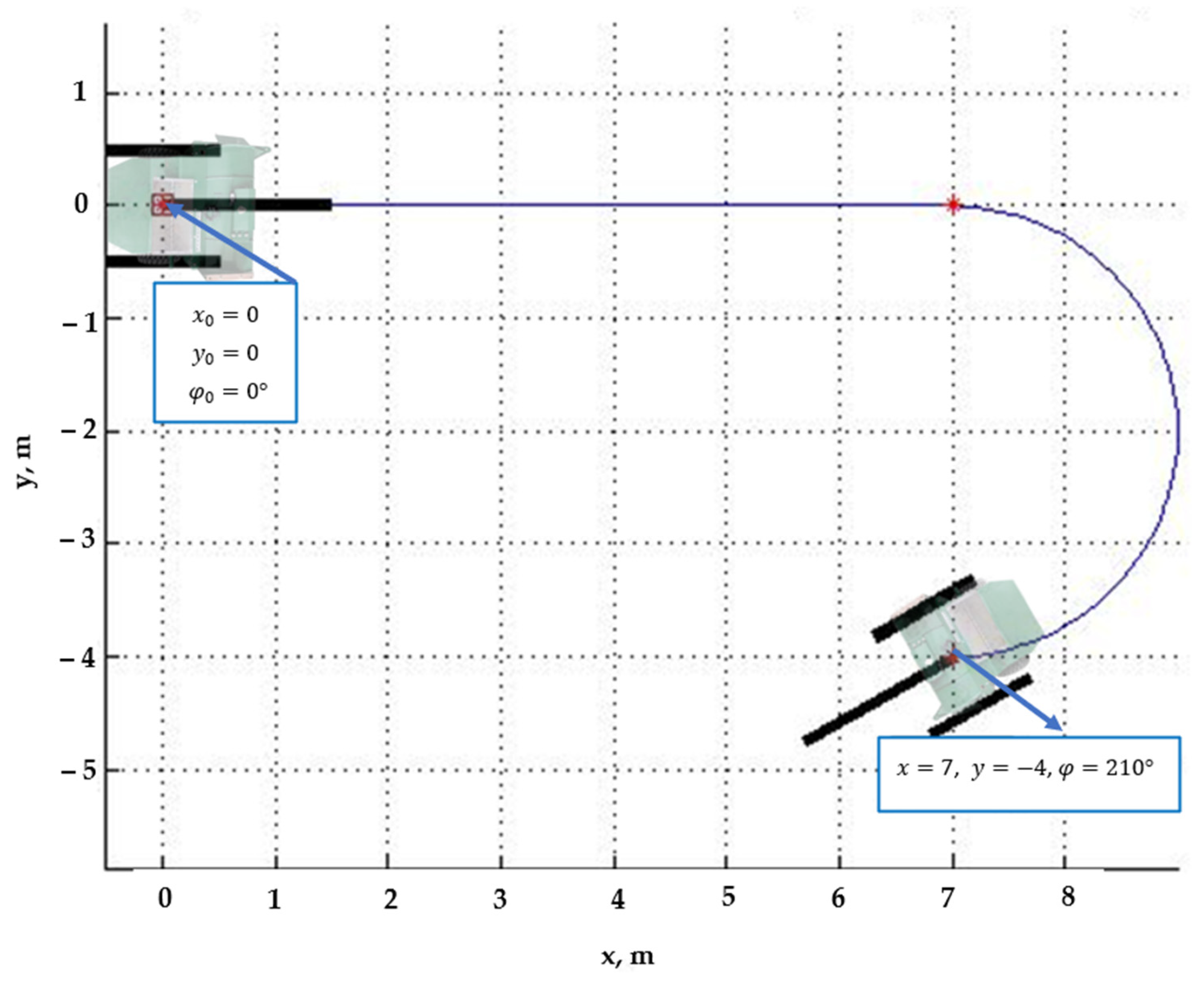
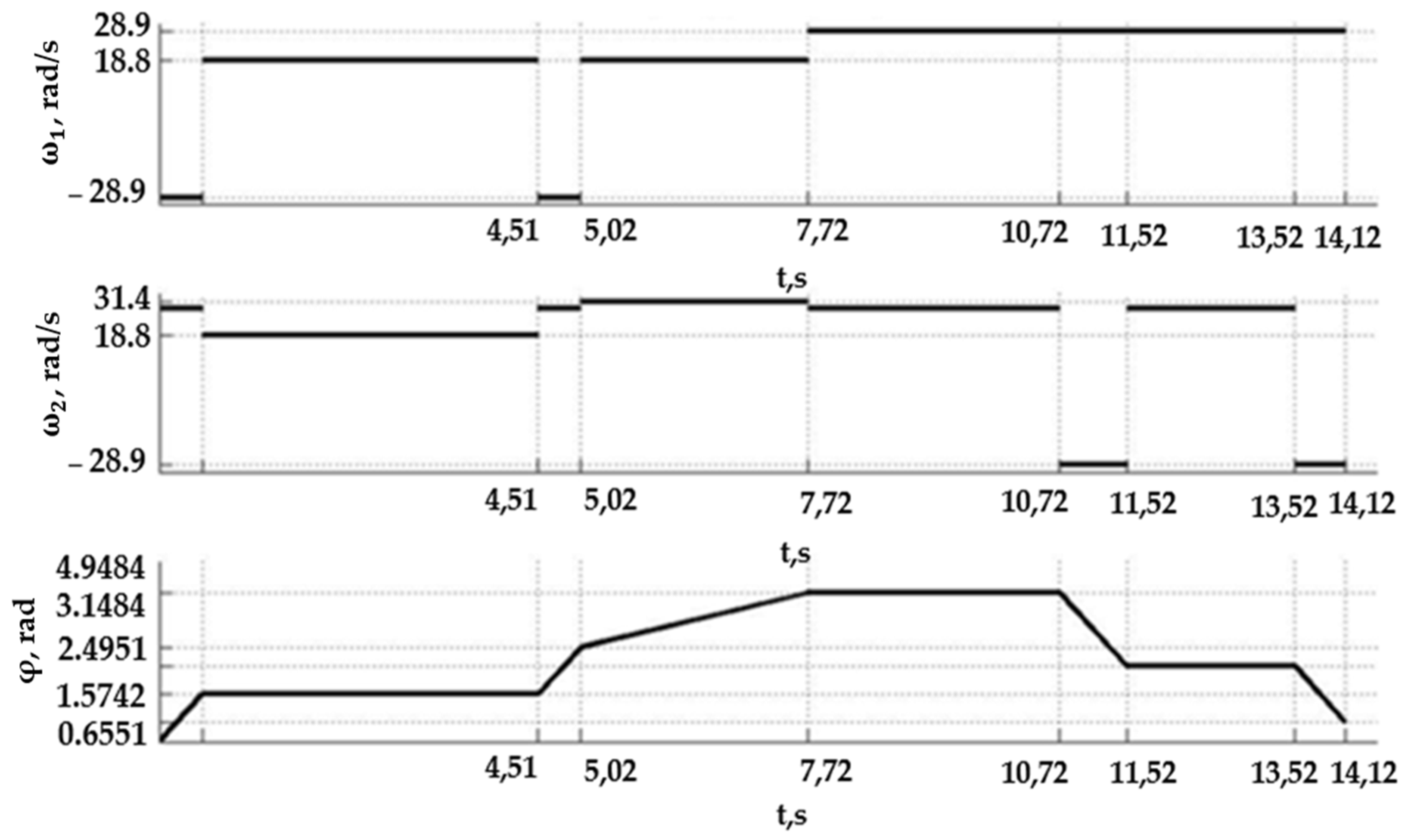
3.2. Inverse Kinematics Problem

The inverse kinematics problem consists of finding all possible vectors, ω 1 ,   ω 2 ,   t , for the given input parameters x 0 ,   y 0 ,   φ 0 ,   x ,   y ,   φ , where ω 1 ,   ω 2 are angular velocities of the right and left wheels, t is the time of movement along the trajectory, x 0 = 0 , y 0 = 0 , φ 0 = 0 represents the initial position of the robot (Figure 3), x ,   y represent the final coordinates on the abscissa and ordinate axes and φ (Figure 3) represents the final course angle (relative to the horizontal).
During a turn of a robotic device, the system must control the trajectory of the robot’s movement, including estimating the angle of deviation of the robot’s axis from a straight line (Figure 4). This task is implemented using an electronic gyroscope with a signal transmission rate of at least once per second.
Solutions to the inverse kinematics problem are an infinite set. Therefore, let us consider two of the most illustrative and applicable options for real conditions—movement in a straight line and along a circle.
Shortest path (in a straight line).
The following motion sections are considered:
  • Turn from the initial position;
  • Uniform rectilinear motion;
  • Turn to the specified angle.
Set the final values:
x = 5 ;   y = 3 ;   φ = 90 °
The dependence of the calculated vector ω 1 ,   ω 2 ,   φ on the calculated vector t is presented in Figure 5; the trajectory of the robot’s movement is presented in Figure 5.
The testing of the automatic control system of the robotic device was carried out using simulation modeling, which involved moving the robot to a coordinate point with the construction of the shortest trajectory of movement (Figure 6).
The following stages of movement are considered:
  • Turning from the initial position (if x < 0 );
  • Uniform rectilinear motion;
  • Circular motion;
  • Turning to the given angle.
For the given values:
x = 7 ,   y = 4 ,   φ = 210 °
The process of turning execution is illustrated in Figure 7.
As a result of solving the problem, a relationship was obtained between the initial and final coordinates of the robot’s position and its linear velocity with the angular velocity of rotation of each drive wheel.

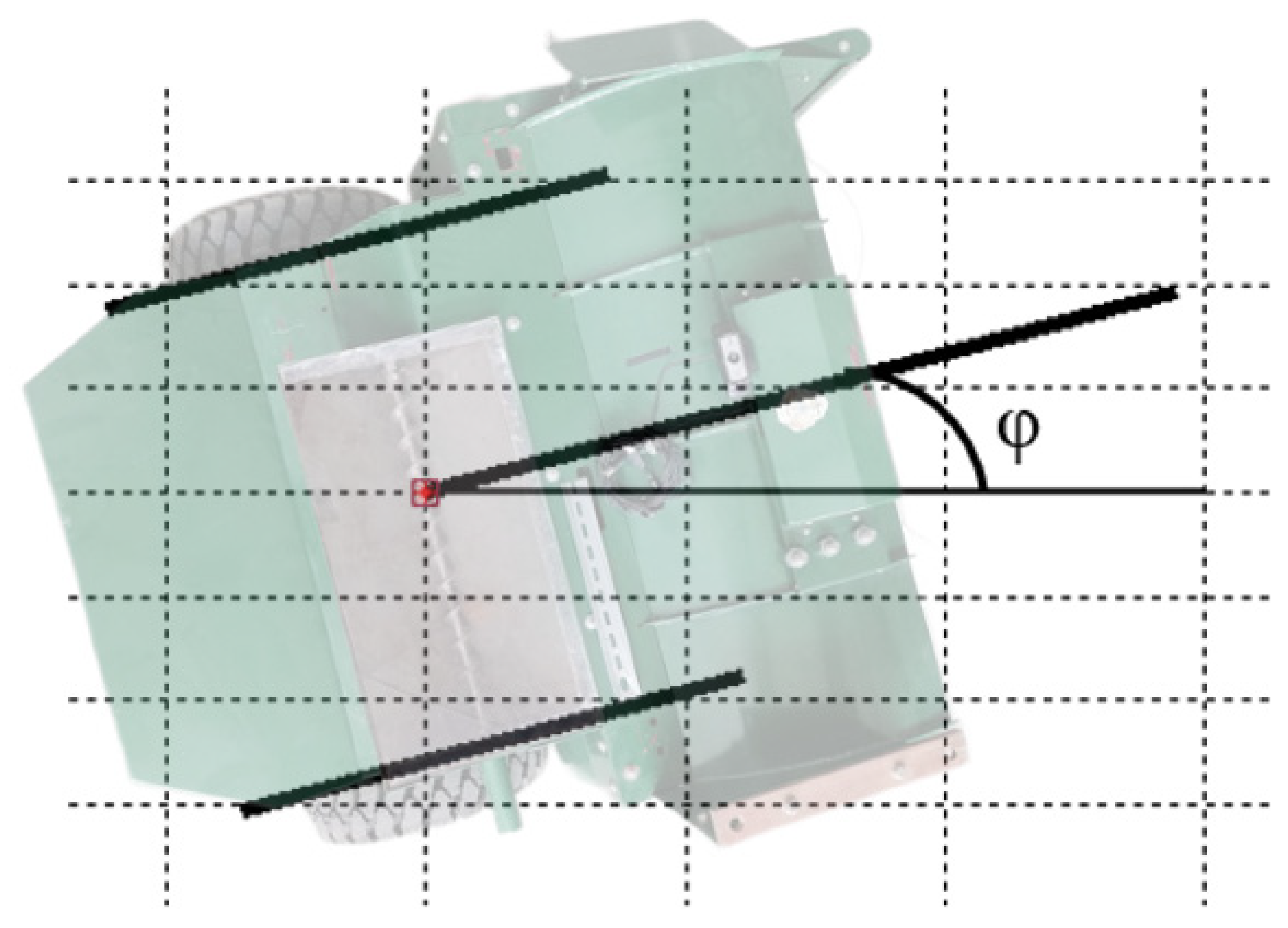
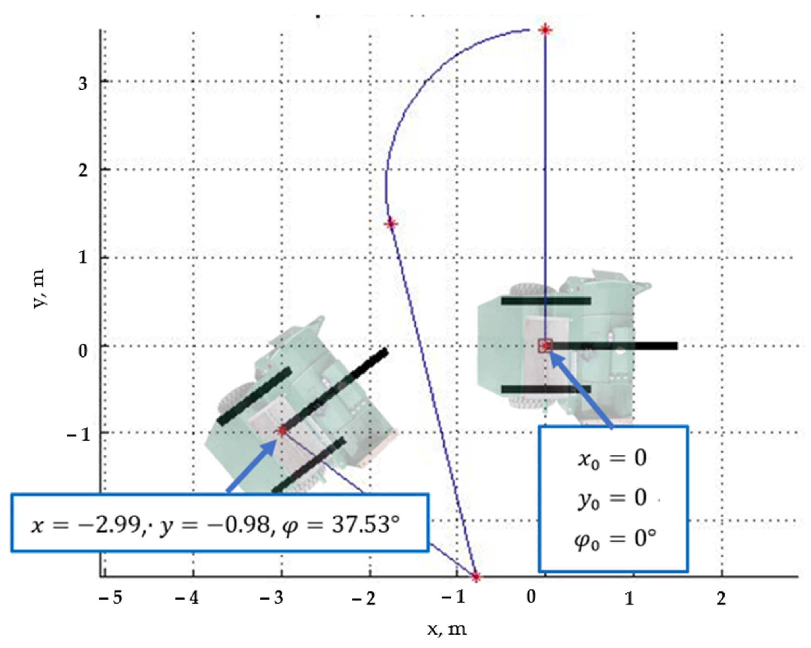
3.3. The Forward Kinematics Problem

The forward kinematics problem involves finding the final values for x ,   y ,   φ given the input vectors ω 1 ,   ω 2 ,   t and initial coordinates x 0 ,   y 0 ,   φ 0 .
The specified values are described in Table 1.
The robot’s trajectory is shown in Figure 8, and the dependence of the given vectors ω 1 ,   ω 2 ,   φ on the vector t is presented in Figure 9.
Then, the forward kinematics problem was solved, which included moving through several positions with specific coordinates and performing movements along a straight line, at an angle and with a smooth turn.
The result of calculating the coordinates after each movement is presented in Table 2.
As a result of solving the problem, a relationship was obtained between the angular rotation speed of each drive wheel and its linear velocity with the robot’s position coordinates.

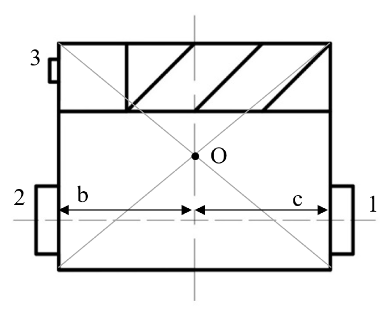
3.4. Dynamic Characteristics of Robot Motion

The dynamics of the robot establishes the relationship between the robot’s dimensions, the forces applied to its elements and the moments.
When considering the dynamics of the robot, the problem of determining the rotating moments of each driving wheel with a normal and offset center of mass (CM) was solved.
M 1 = λ m 1 g R · c
M 2 = λ g · m 2 R + m 3 r · b
m 1 m 2 , m 3 = a + b · m 2 + c · m 2 2 + d · m 2 3 + e · m 2 4 + f · m 3 + g · m 3 2 + h · m 3 3 + i · m 3 4 + j · m 3 5 ,  
M 1 ,   M 2 —moments of the motors controlling the rotation of the right and left driving wheels, respectively;
λ —coefficient of friction (tire–road);
R —radius of the driving wheels;
r —radius of the front auxiliary wheel;
m 1 ,   m 2 ,   m 3 —masses for the right driving, left driving, and front auxiliary wheels, respectively;
b, c—distances from the edge of the robot to the center of mass.
Equation (11), is the equation of the plane describing the dependence of m 1 on m 2 and m 3 if the center of mass deviates from the normal position shown in Figure 10.
Equation (7) was derived by digitizing the matrix of values m 1 ,   m 2 ,   m 3 as the position of the center of mass of the robot was changed (Table 3). The matrix was obtained empirically. Each cell contains data in fractions of the total mass of the robot (Figure 10).
m = m 1 + m 2 + m 3     m 1 = m 1 m ;   m 2 = m 2 m ;   m 3 = m 3 m     m = m 1 + m 2 + m 3 = 1  
Each cell corresponds to data taken at twenty-five different positions of the center of mass (Figure 11).
This made it possible to identify the following dependencies presented in Table 3.
Analysis of the data table showed:
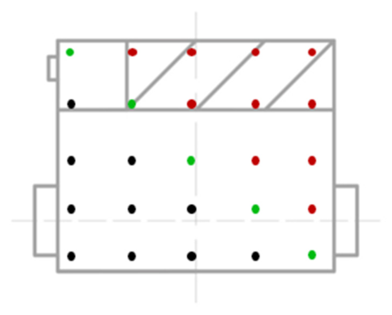
  • When the CM falls on the main diagonal (highlighted in gray in Table 3), the robot is in a state of equilibrium, relying only on the right driving and front auxiliary wheels; there is no load on the left driving wheel;
  • When the CM falls in the area above the main diagonal (highlighted in red in Figure 11) of the matrix, the robot may tip over turning a corner.
In a real robot, the normal position of the center of mass is shifted to the area below the main diagonal, so a large effort is required to tip the robot over (Figure 12).
A plane was constructed based on the data matrix. Additionally, a function of the dependence of m 1 m 2 , m 3 was derived from the matrix in the program Table Curve 3D v4.0:
m 1 m 2 , m 3 = a + b · m 2 + c · m 2 2 + d · m 2 3 + e · m 2 4 + f · m 3 + g · m 3 2 + + h · m 3 3 + i · m 3 4 + j · m 3 5 ,

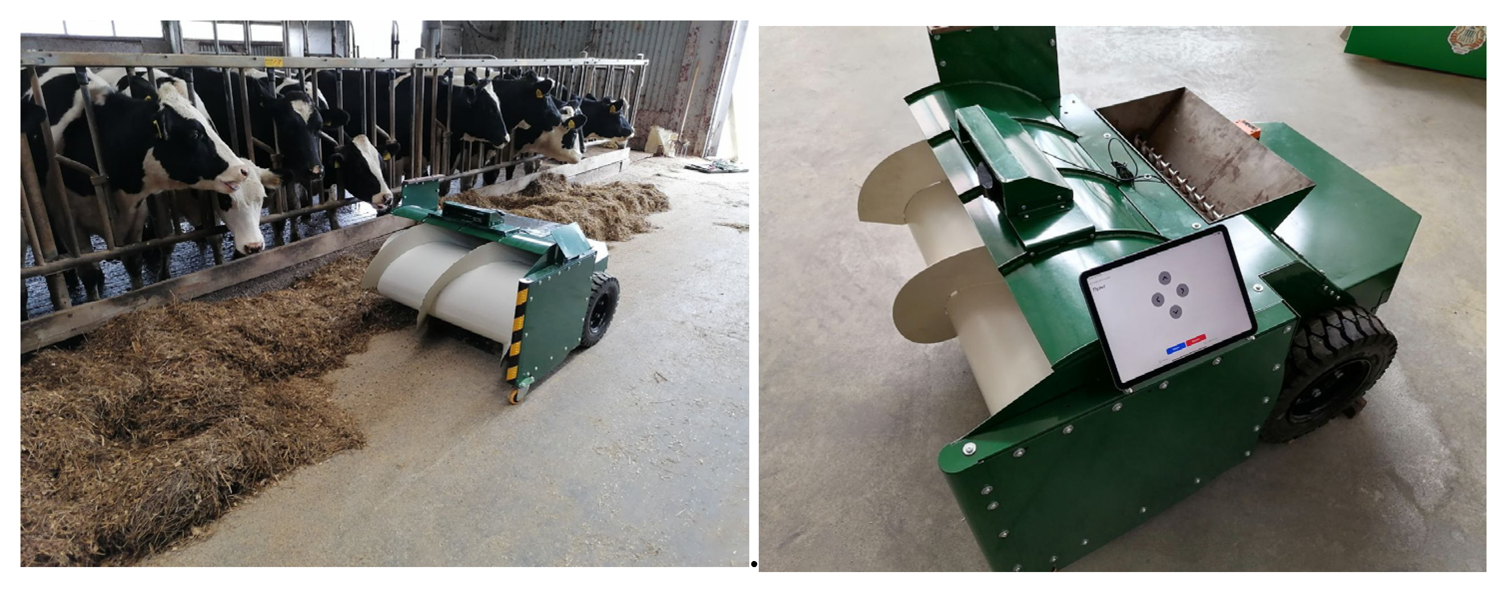
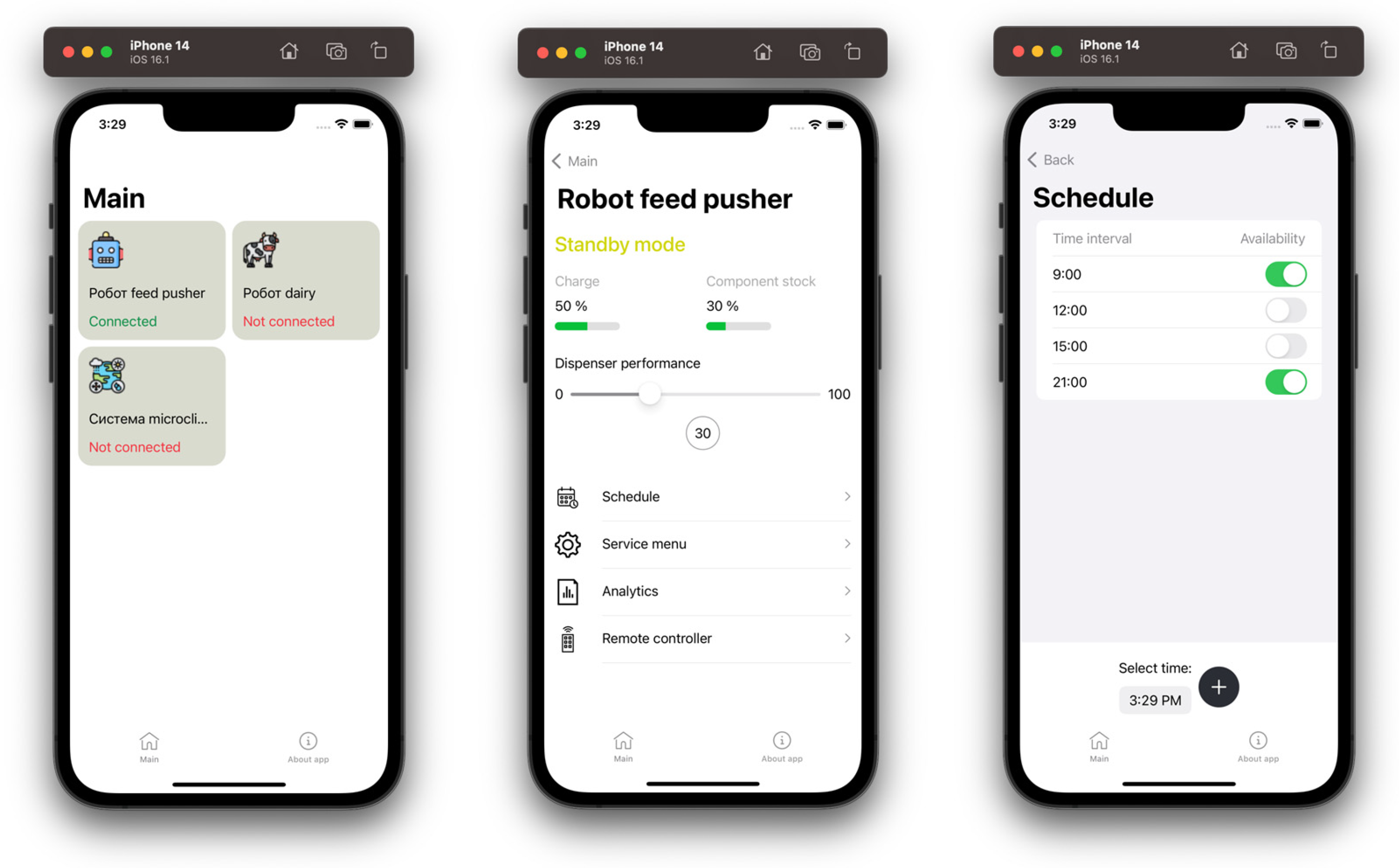
3.5. Testing Mobile Application and Robot on Farm

Within the operational testing of the feed-pusher robot, its functions were tested, as their implementation represented the effectiveness that the proposed robot would have on the farm:
  • Change of undercarriage operating modes during the elaboration of turning was carried out automatically without human intervention;
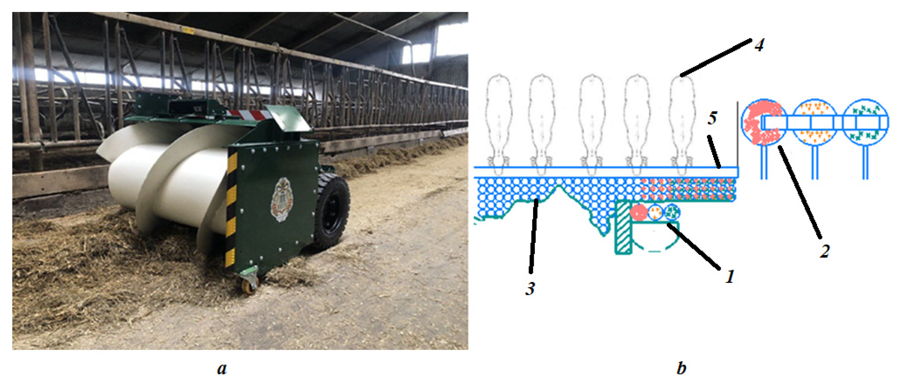
  • Movements of the robot along the feed alley and autonomous performance of operations (pushing feed to the fence of the feed alley, dosing feed additives, taking into account the remaining amount of key feed rations);
  • Remote monitoring of the robot conditions using a smartphone (battery charge level, feed filling level).
Nevertheless, the robot was developed for the Russian market, which is characterized by a harsh climate where the temperature inside the farm often drops to −10 °C. Therefore, the duration of the autonomous operation of the robot without recharging at temperatures of −20 °C and above should be more than 2 h, since this ensures the capacity of a battery power supply system of 250 Ah.
At the same time, the robot performs two technological operations (dosing of feed additives and moving along the fence of the feed alley). This requires four electric servo drives: two of them are applied for rotating the drive wheels, one is for driving the pusher and one is used for the feeding additive dispenser.
The frequency of information exchange between the central control board of the device and the mobile software is twice per second.
In addition to the system of inductive sensors used in the positioning system, the robot is equipped with a computer vision system that allows adaptive adjustment of the robot’s movement trajectory relative to the boundary of the feed mixture spread.

3.6. Figma Tool for Creating Mobile Application Design

The free Figma system was used as the design tool as the design was made for the most common device size. The developed application prototypes are shown in Figure 13.

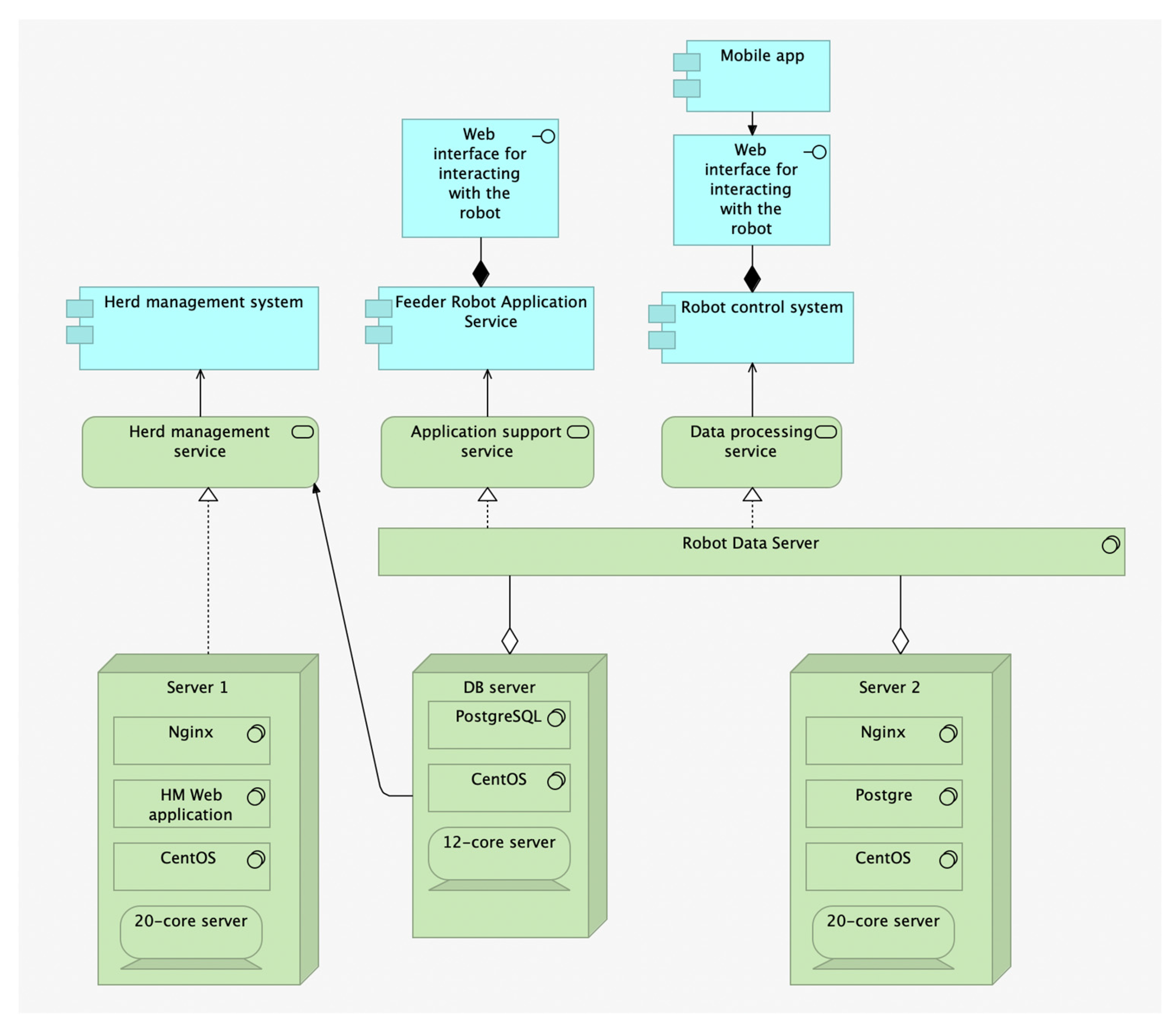
3.7. Designing the Solution Architecture via the Tool Archi

For designing the technical architecture, the Archi tool was applied.
The farm already has a system of dairy cattle management. The new services for the robot ecosystem that were added were:
  • An application service for the feed-pusher robot. This is required for direct control of the robot; it interacts with the robot using the Web interface;
  • Robot control service. This is the key service to ensure the operation of the ecosystem; the user application interacts with this service.
The software architecture is shown in the Figure 14.
The Wi-Fi network is used to interact with the robot. The mobile application generates JSON objects and sends them through an intermediate server using the REST API. The web interface for interacting with the robot receives the objects and sends them to the robot, also via Wi-Fi.
The operations of receiving information are performed by GET requests; the operations of interacting with the robot are performed by POST requests.
Each request from the mobile application sends the robot’s metadata in the HTTP request header. The metadata is stored in the robot data server. The metadata includes the operating status of the robot, coordinates of the current location, operating time, component reserve, technical characteristics such as battery charge, serviceability of the navigation, the transmission and the screw systems.

4. Discussion

Currently, there are quite a few stand-alone robotics solutions and digital platforms for animal husbandry on the market. Thus, an easy-to-use digital platform is fundamental for sustainable application. Advantages such as an easy-to-learn interface and an affordable user support are relevant. The proposed system takes into account these problems, as we reported in earlier studies [34].
Furthermore, currently on farms there is a situation that suggests the use of several monitoring systems for different robots and sensors, which is an inconvenient solution [35].
Moreover, farmers want to have access to all the data that robots and sensors receive to make the access more transparent. This is a problem in the existing ecosystems [36]. The process of obtaining reports is extremely difficult. By using a common database and adjacent tables in the proposed solution, the problem is solved [37].
The introduction of the robot ecosystem is optimal, not only in terms of optimizing the business process and minimizing the human factor but also in terms of increasing the farm’s profitability. Additionally, robot manufacturers will be able to save on consumables and additional equipment [38,39].
However, there are the following disadvantages: the testing of the ecosystem was carried out on a farm with an initial level of digitalization, the ecosystem management application is designed for mobile devices only and problems with an intermittent unstable connection between the robot and the server were identified; the latter problem has been repeatedly mentioned in other studies related to digitalization in crop production [40,41,42,43,44,45].
Therefore, further work will be related to the improvement of the network equipment and optimization of the connection. There are plans to develop an application for operating via a Web browser and for adding more features in terms of variety of access types and roles. Furthermore, support for robots from different manufacturers should be added for seamless integration into the developed system.

5. Conclusions

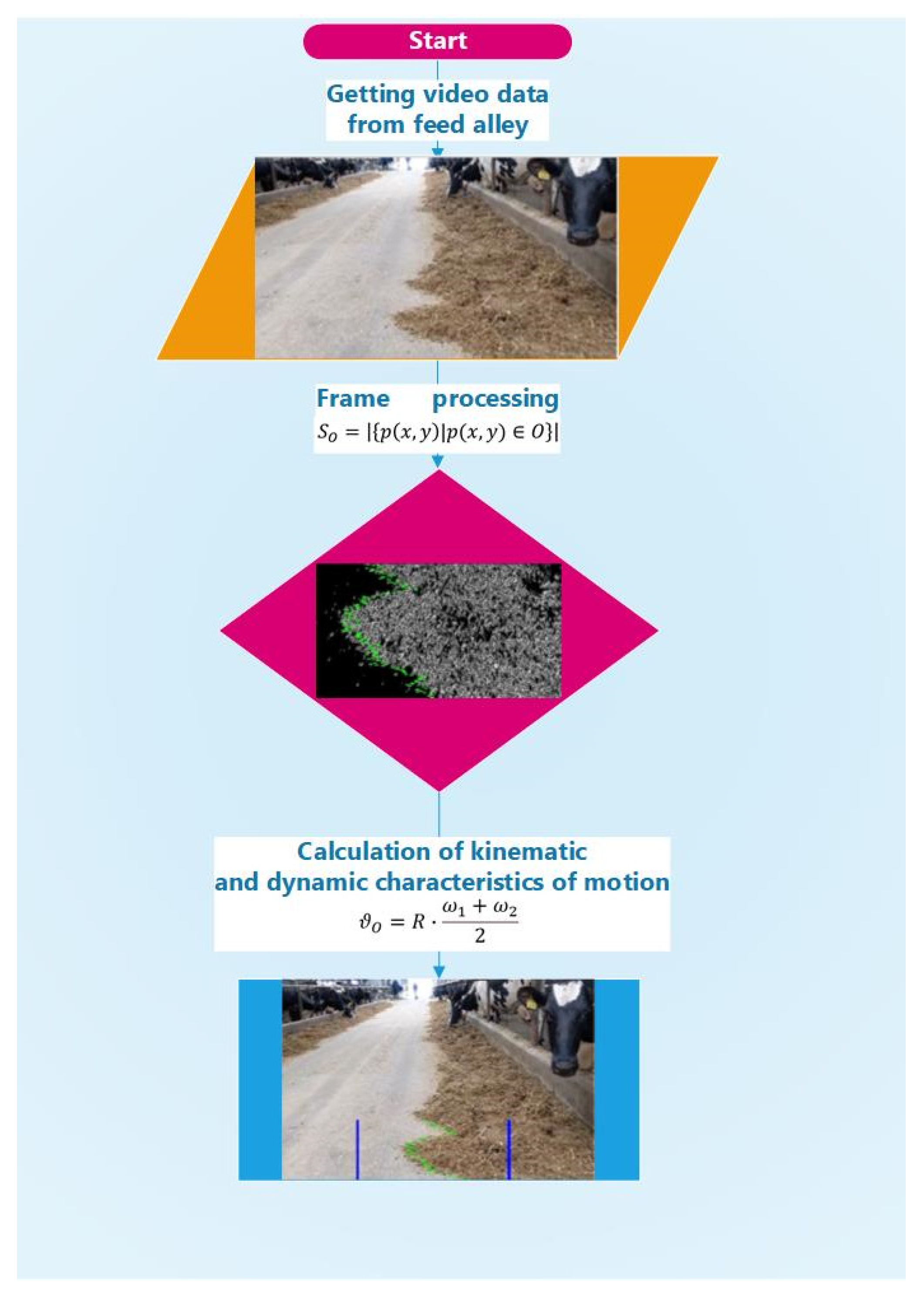
  • The authors have developed an algorithm for the automatic positioning system of a wheeled robot with the unique capabilities of a software and hardware complex based on an RGB camera that allows determination of the volume of feed in the feeding alley and guiding the robot along the alley;
  • The maximum positioning error of the robot using the developed algorithm for the vision system did not exceed 20 mm relative to the center of mass of the robot during the tests;
  • The authors have developed mobile application that allows for adjustments to the device’s operation regardless of location, 24/7. The operator received an alert on their smartphone when the amount of feed on the feed table was below critical.

Author Contributions

Conceptualization and methodology, E.A.N.; supervision and funding acquisition, E.A.N.; project administration, D.Y.P.; validation, D.Y.P.; validation, I.A.G.; formal analysis, D.V.S.; writing—original draft preparation, D.V.S.; writing—original draft preparation, E.A.N.; writing—original draft preparation, I.A.G.; visualization, E.C.; formal analysis, S.M.; formal analysis M.V.B.; writing—original draft preparation, M.V.B. All authors have read and agreed to the published version of the manuscript.

Funding

This work was supported by the Ministry of Education and Science of the Russian Federation in the framework of the State Assignment of “Federal Scientific Agroengineering Center VIM” (topic No. FGUN 2022-0014).

Institutional Review Board Statement

The animal study protocol was approved by the Ethics Committee of Federal scientific agroengineering center VIM (protocol code 321 and date of approval 15 jule 2022).” for studies involving animals.

Informed Consent Statement

Written informed consent has been obtained from the patient(s) to publish this paper.

Data Availability Statement

Data available on request due to restrictions eg privacy or ethical.

Conflicts of Interest

The authors declare no conflict of interest.

References

  1. Shahbandeh, M. Global Cow Milk Production 2015 to 2020. Available online: https://www.statista.com/topics/4649/dairyindustry/ (accessed on 1 June 2023).
  2. Klerkx, L.; Jakku, E.; Labarthe, P. Review of Social Sciences on Digital Agriculture, Smart agriculture and Agriculture 4.0: New materials and a program for future research. NJAS Wagening. J. Life Sci. 2019, 90–91, 100315. [Google Scholar] [CrossRef]
  3. Fox, G.; Mooney, J.; Rosati, P.; Lynn, T. Innovators of agricultural technology: A study of the initial introduction and further use of a mobile digital platform by family farming enterprises. Agric. Ind. 2021, 11, 1283. [Google Scholar] [CrossRef]
  4. Kassahun, A.; Blue, R.; Katal, S.; Mishra, A. Dairy farm management information systems. Electronics 2022, 11, 239. [Google Scholar] [CrossRef]
  5. Luis, O.; Tedeschi, P.L.; Greenwood, I.G. Advances in sensor technology and intelligent decision support tools to promote intelligent animal husbandry. J. Anim. Sci. 2021, 99, skab038. [Google Scholar] [CrossRef]
  6. Nikitin, E.A. The system of robotic maintenance of the feed lot at livestock complexes. Mach. Equip. Rural. Areas 2020, 276, 26–30. [Google Scholar] [CrossRef]
  7. Pavkin, D.Y.; Shilin, D.V.; Nikitin, E.A.; Kiryushin, I.A. Design and modeling of the control process of a feed pusher robot used on a dairy farm. Appl. Sci. 2021, 11, 10665. [Google Scholar] [CrossRef]
  8. Reger, M.; Bernhardt, H.; Stumpenhausen, J. Navigation and personal protection in automatic power systems. Actual Tasks Agric. Eng. 2017, 45, 523–530. [Google Scholar]
  9. John, A.J.; Freeman, M.J.; Kerrisk, K.F.; Garcia, S.C.; Clark, C.E.F. Robotic use of pasture dairy cows with different milking frequency. Animal 2019, 13, 1529–1535. [Google Scholar] [CrossRef]
  10. ABach, N.; Valls, A.; Solans, T. Torrent Associations between nondietary factors and dairy herd performance. J. Dairy Sci. 2008, 91, 3259–3267. [Google Scholar] [CrossRef] [Green Version]
  11. Galakhmi, I.; Edan, Y.; Malts, E.; Peiper, U.M.; Muallem, U.; Brukenthal, I. Real-time monitoring system of individual feed consumption by a dairy cow. Comput. Electron. Agric. 1998, 20, 131–144. [Google Scholar] [CrossRef]
  12. Schneider, L.; Volkmann, N.; Kemper, N.; Spindler, B. Feeding behavior of fattening bulls fed six times a day using an automatic feeding system. Boundaries Vet. Sci. 2020, 7, 43. [Google Scholar] [CrossRef] [PubMed] [Green Version]
  13. Bukens, M.; Bukabu, A.; Chadli, M. Robust adaptive approach to trajectory tracking management based on a neural network for uneconomical mobile robots with electric drive. Robot. Auton. Syst. 2017, 92, 30–40. [Google Scholar] [CrossRef]
  14. Gene, H. Fault-tolerant iterative learning control for mobile robots with non-repeating trajectory tracking with output restrictions. Automatica 2018, 94, 63–71. [Google Scholar] [CrossRef]
  15. De Berg, M.; Gerrits, D.H.P. Computational ejection schemes for robots in the form of a disk. Int. J. Comput. Geom. Appl. 2013, 23, 29–48. [Google Scholar] [CrossRef] [Green Version]
  16. Wu, X.; Jin, P.; Zou, T.; Qi, Z.Y.; Xiao, H.N.; Lu, P.H. Tracking the trajectory of the reverse step based on fuzzy sliding mode control for differential mobile robots. J. Intell. Robot. Syst. 2019, 96, 109–121. [Google Scholar] [CrossRef]
  17. Sekiguchi, S.; Yorozu, A.; Kuno, K.; Okada, M.; Watanabe, Y.; Takahashi, M. Development of a human-friendly control system for a two-wheeled service robot with an optimal approach to management. Robot. Auton. Syst. 2020, 131, 103562. [Google Scholar] [CrossRef]
  18. Miller-Cushon, E.K.; DeVries, T.J. Feed sorting in dairy cattle: Causes, consequences, and management. J. Dairy Sci. 2017, 100, 4172–4183. [Google Scholar] [CrossRef] [PubMed]
  19. Bach, A.; Iglesias, K.; Busto, I. Technical Note: A computerized system for monitoring feeding behavior and individual feed consumption by dairy cattle. J. Dairy Sci. 2004, 87, 4207–4209. [Google Scholar] [CrossRef]
  20. Nithirajan, S.; Kemp, B. Digital animal husbandry. Sens. Biosensory Res. 2021, 32, 100408. [Google Scholar]
  21. Ota, T.; Iwasaki, Y.; Nakano, A.; Kuribara, H.; Higashide, T. Development of yield and harvesting time monitoring system for tomato greenhouse production. Eng. Agric. Environ. Food 2018, 12, 40–47. [Google Scholar] [CrossRef]
  22. Gupta, G.S.; Seelye, M.; Seelye, J.; Bailey, D. Autonomous Anthropomorphic Robotic System with Low-Cost Colour Sensors to Monitor Plant Growth in a Laboratory; In-Tech: London, UK, 2012; 22p. [Google Scholar]
  23. Nikitin, E.A.; Dorokhov, A.S.; Pavkin, D.Y. Improving the technology of preparation of feed mixture during the reconstruction of feeding grounds. Mach. Equip. Village 2019, 269, 32–34. (In Russian) [Google Scholar] [CrossRef]
  24. Dos Santos, F.N.; Sobreira, H.M.P.; Campos, D.F.B.; Morais, R.; Moreira, A.P.G.M.; Contente, O.M.S. Towards a reliable monitoring robot for mountain vineyards. In Proceedings of the 2015 IEEE International Conference on Autonomous Robot Systems and Competitions, Vila Real, Potugal, 8–10 April 2015; pp. 37–43. [Google Scholar] [CrossRef]
  25. Pezzuolo, A.; Cumenti, A.; Sartori, L.; Da Borso, F. Automatic feeding systems: Assessment of energy consumption and labor needs on a dairy farm in northeastern Italy. Eng. Rural. Dev. 2016, 15, 882–887. (In English) [Google Scholar]
  26. Dos Santos Xaud, M.F.; Leite, A.C.; Barbosa, E.S.; Faria, H.D.; Loureiro, G.; From, P.J. Robotic tankette for intelligent bioenergy agriculture: Design, development and field tests. In Proceedings of the XXII Congresso Brasileiro de Automatica (CBA2018), Joao Pessoa, Brazil, 9–12 September 2018; p. 1357. [Google Scholar] [CrossRef]
  27. Kupreenko, A.I.; Isaev, H.M.; Mikhailichenko, S.M. Operation of an automatic feed wagon on a dairy farm [Electronic resource]. Tract. Agric. Mach. 2018, 40, 32–33. [Google Scholar]
  28. Da Borso, F.; Ciumenti, A.; Sigura, M.; Pezzuolo, A. The influence of automatic feeding systems on the design and management of dairy farms. J. Agric. Eng. 2017, 48, 48–52. (In English) [Google Scholar] [CrossRef] [Green Version]
  29. Obershetzl, R.; Haydn, B.; Neiber, J.; Neser, S. Automatic cattle feeding systems—A study of energy consumption of technologies. In Proceedings of the XXXVI Conference CIOSTA CIGR V, St. Petersburg, Russia, 26–28 May 2015; pp. 1–9. [Google Scholar]
  30. Vdovenko, V.N. Automated feeding systems (SAK) [Automated feeding systems (AFS)]. Farmer Volga Area 2017, 65, 80–89. [Google Scholar]
  31. Tangorra, F.M.; Calcante, A. Energy consumption and technical and economic analysis of an automatic feeding system for dairy farms: Results of field tests. J. Agric. Eng. 2018, 49, 228–232. (In English) [Google Scholar] [CrossRef]
  32. Kupreenko, A.I.; Isaev, H.M.; Grin, A.M.; Mikhailichenko, S.M.; Kolomeichenko, A.V.; Kuznetsov, Y.u.A.; Kalashnikova, L.V. Automated feed mixture distribution system using a feeding trolley. Inmatech Agric. Eng. 2019, 58, 239–246. [Google Scholar]
  33. Bayati, M.; Fotouhi, R. A mobile robotic platform for crop monitoring. Adv. Robot. Autom. 2018, 7, 1000186. [Google Scholar] [CrossRef]
  34. Dorokhov, A.S.; Nikitin, E.A.; Pavkin, D.Y. Wheeled robotic technical means: Experience and prospects of use on livestock complexes. Mach. Equip. Village 2022, 298, 16–21. [Google Scholar] [CrossRef]
  35. Bisaglia, K.; Belle, Z.; Van den Berg, G.; Pompe, J. Automatic versus Traditional feeding systems on robotic milking dairy farms: A study in the Netherlands. In Proceedings of the International Conference of Agricultural Engineering CIGR-AgEng, Valencia, Spain, 8–12 July 2012; pp. 100–104. [Google Scholar]
  36. Grotman, A.; Nidegger, F.; Hausermann, A.; Hartung, E. Automatic feeding system (AFS)—Optimization potential in dairy farming. Landtechnik 2010, 65, 129–131. [Google Scholar]
  37. Oliveira, L.; Moreira, A.P.; Silva, M.F. Advances in agriculture robotics: A state-of-the-art review and challenges ahead. Robotics 2021, 10, 52. [Google Scholar] [CrossRef]
  38. Saiz, V.; Rovira, F. From smart farming towards agriculture 5.0: A review on crop data management. Agronomy 2020, 10, 207. [Google Scholar] [CrossRef] [Green Version]
  39. Hang, L.; Tang, L.; Steven, W.; Mei, Y. A robotic platform for corn seedling morphological traits characterization. Sensors 2017, 17, 2082. [Google Scholar] [CrossRef] [Green Version]
  40. Xie, Z.J.; Gu, S.; Chu, Q.; Li, B.; Fan, K.J.; Yang, Y.; Yang, Y.; Liu, X. Development of a high-productivity grafting robot for Solanaceae. Int. J. Agric. Biol. Eng. 2020, 13, 82–90. [Google Scholar] [CrossRef]
  41. Jiang, K.; Zhang, Q.; Chen, L.P.; Guo, W.Z.; Zheng, W.G. Design and optimization on rootstock cutting mechanism of grafting robot for cucurbit. Int. J. Agric. Biol. Eng. 2020, 13, 117–124. [Google Scholar] [CrossRef]
  42. Treiber, M.; Hillerbrand, F.; Bauerdick, J.; Bernhardt, H. On the current state of agricultural robotics in crop farming—Chances and risks. In Proceedings of the 47th Int Symposium “Actual Tasks Agriculture Engineering”, Opatija, Croatia, 5–7 March 2019; pp. 27–33. [Google Scholar]
  43. Scholz, C.; Moeller, K.; Ruckelshausen, A.; Hinck, S.; Goettinger, M. Automatic soil penetrometer measurements and gis-based documentation with the autonomous field robot platform bonirob. In Proceedings of the 12th International Conference of Precision Agriculture, Sacramento, CA, USA, 20–23 July 2014. [Google Scholar]
  44. Saiz, V.; Rovira, F.; Millot, C. Performance improvement of a vineyard robot through its mechanical design. In Proceedings of the 2017 ASABE Annual International Meeting, Washington, DC, USA, 16–19 July 2017; p. 1701120. [Google Scholar] [CrossRef]
  45. Xu, E.; Hou, B.M.; JiaNa, B.I.; Shen, Z.G.; Wang, B. Smart agriculture based on internet of things. In Proceedings of the 2nd International Conference on Robotics, Electrical and Signal Processing Techniques, Dhaka, Bangladesh, 5–7 January 2021; pp. 157–162. [Google Scholar] [CrossRef]
Figure 1. Robot movement technology. (a) Developed feed pusher robot; (b) schematic diagram of the robot movement. 1—robot feed pusher; 2—charging station with feed additive bins; 3—feed border; 4—dairy cattle; 5—overhand timber.
Agriculture 13 01422 g001
Figure 2. Functioning of the technical vision system for the robot feeder.
Agriculture 13 01422 g002
Figure 3. Initial position of the robot.
Agriculture 13 01422 g003
Figure 4. Heading angle. φ—the angle of deviation of the robot axis.
Agriculture 13 01422 g004
Figure 5. Transient characteristics.
Agriculture 13 01422 g005
Figure 6. Inverse kinematics problem.
Agriculture 13 01422 g006
Figure 7. Inverse kinematics problem for a robot moving in a circular path.
Agriculture 13 01422 g007
Figure 8. ω 1 ,   ω 2 ,   φ as a function of t for all path segments.
Agriculture 13 01422 g008
Figure 9. Forward kinematics problem for robot motion.
Agriculture 13 01422 g009
Figure 10. Conditional diagram of the harvester. 1—right driving wheel, 2—left driving wheel, 3—front auxiliary wheel, O—conditional center of mass of the robot, b, c—distance from the center of mass of the robot, to the support points of the driving wheels.
Agriculture 13 01422 g010
Figure 11. Considered positions of the center of mass.
Agriculture 13 01422 g011
Figure 12. The feed-pusher robot testing process.
Agriculture 13 01422 g012
Figure 13. Interface of the main screens of the mobile application.
Agriculture 13 01422 g013
Figure 14. The principle of building a digital ecosystem in a mobile application for interacting with robots on a farm.
Agriculture 13 01422 g014
Table 1. Specified values.
Type of Motion ω 1 , Rad/s ω 2 , Rad/st, s
Rotation around itself by 90°−28.928.90.51
Uniform rectilinear motion 18.818.84
Rotation around itself by 90°−28.928.90.51
Motion along a circle18.818.82.7
Uniform rectilinear motion28.928.93
Rotation around itself28.9−28.90.8
Uniform rectilinear motion28.928.92
Rotation around itself28.9−28.90.1
Table 2. The result of calculating the coordinates.
x, m0−0.0123−0.012−1.76−0.79−0.79−2.99−2.99
y, m03.63.61.37−2.64−2.64−0.98−0.98
φ , °90.19590.195180.39283.5283.5142.9142.9537.53
Table 3. Mass distribution with center of mass shift.
0.6993 0 0 0 0
00.302400000000
0.6033 0.5747 0 0 0
0.09750.300700.4268000000
0.5103 0.5096 0.5053 0 0
0.18500.30420.07090.421100.49670000
0.4165 0.4065 0.4243 0.4196 0
0.28710.29690.17140.42280.07190.505500.581200
0.3052 0.3074 0.3067 0.2994 0.2961
0.40150.29290.28130.41180.19560.49870.12620.574900.7046
Disclaimer/Publisher’s Note: The statements, opinions and data contained in all publications are solely those of the individual author(s) and contributor(s) and not of MDPI and/or the editor(s). MDPI and/or the editor(s) disclaim responsibility for any injury to people or property resulting from any ideas, methods, instructions or products referred to in the content.

