
Design of a Teat Cup Attachment Robot for Automatic Milking Systems


Abstract
:1. Introduction
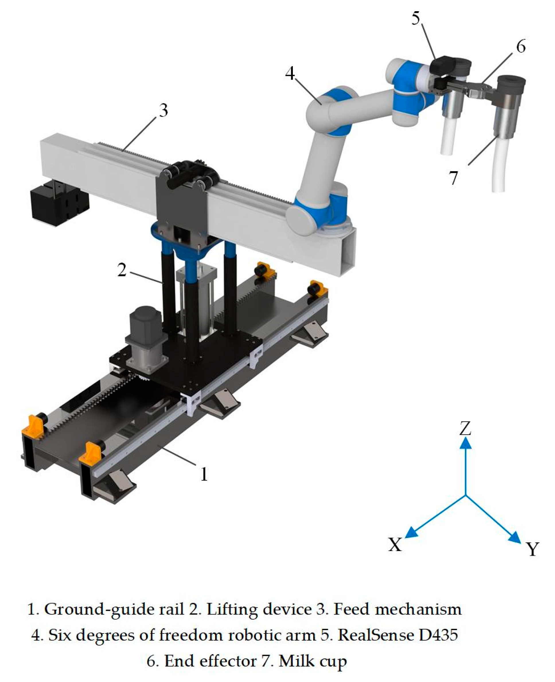
2. System Design
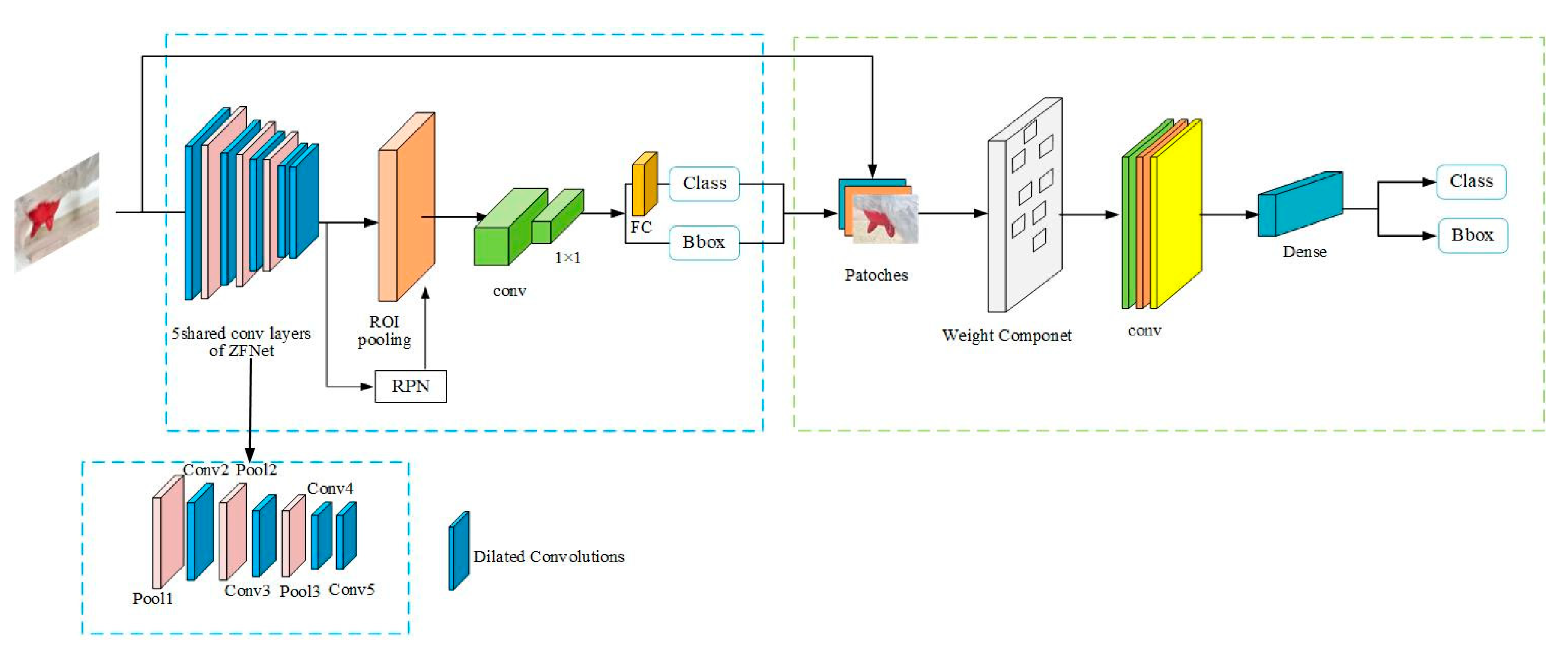
2.1. Visual Perception
2.2. Structural Design Based on TRIZ
2.2.1. Description of the Problem
2.2.2. Mechanical Arm Design Based on the TRIZ Contradiction Matrix
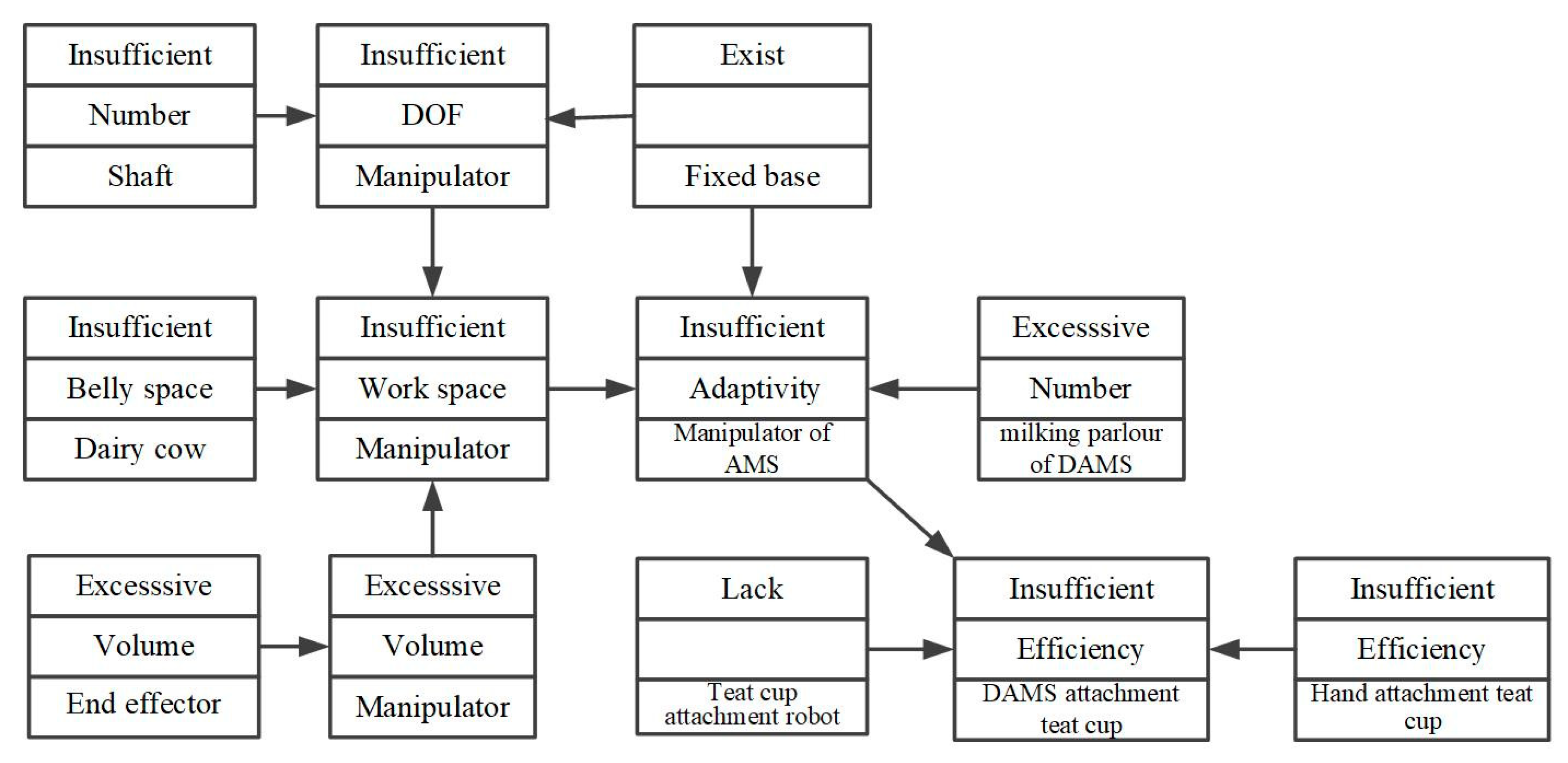
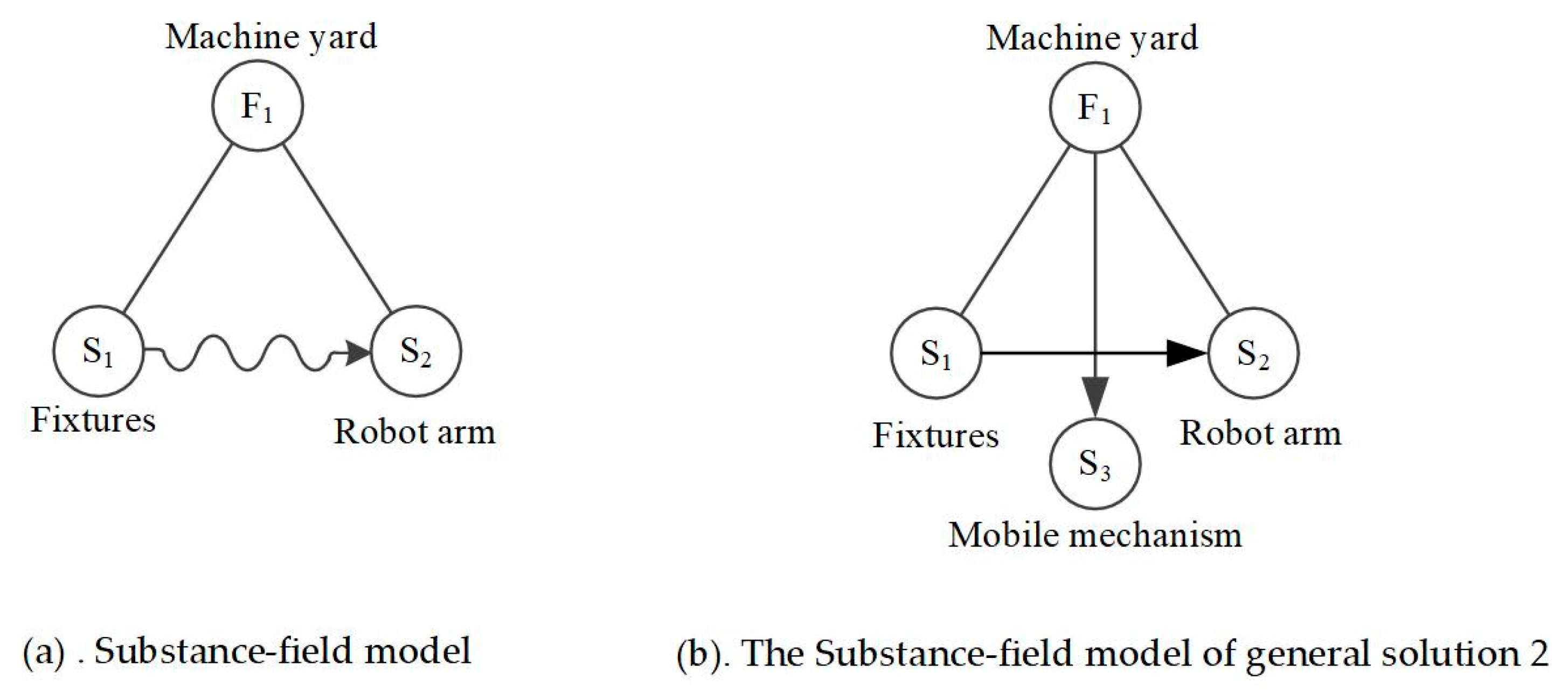
2.2.3. Three-Degrees-of-Freedom Posture Adjustment System Based on a Substance-Field Analysis
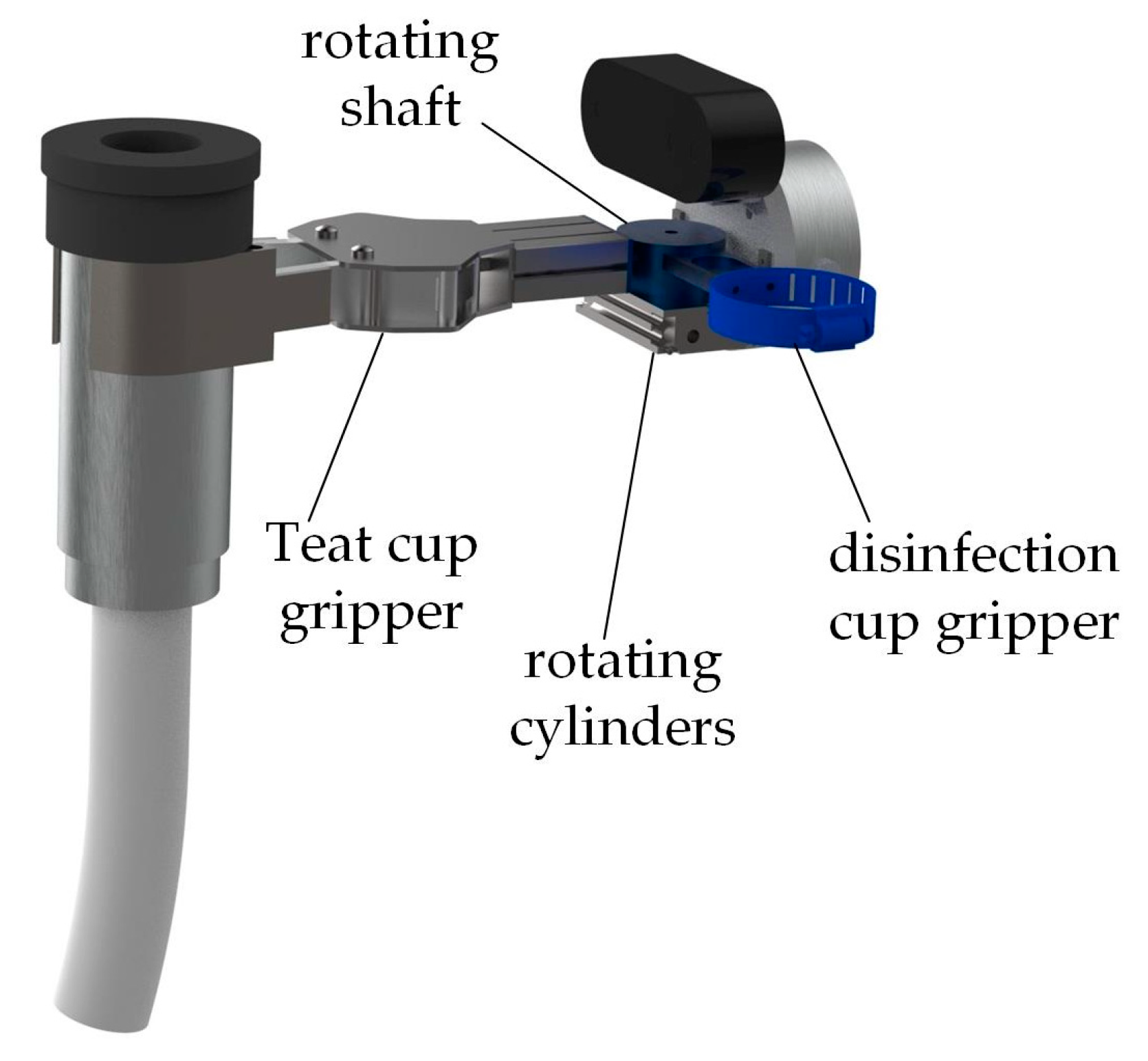
2.2.4. Integration of Technical Solutions
3. Simulation Analysis of Workspaces
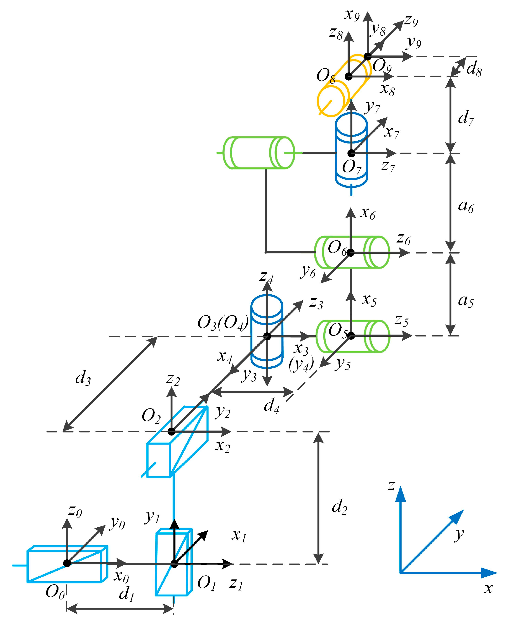
3.1. Theoretical Analysis
3.2. Simulation Verification
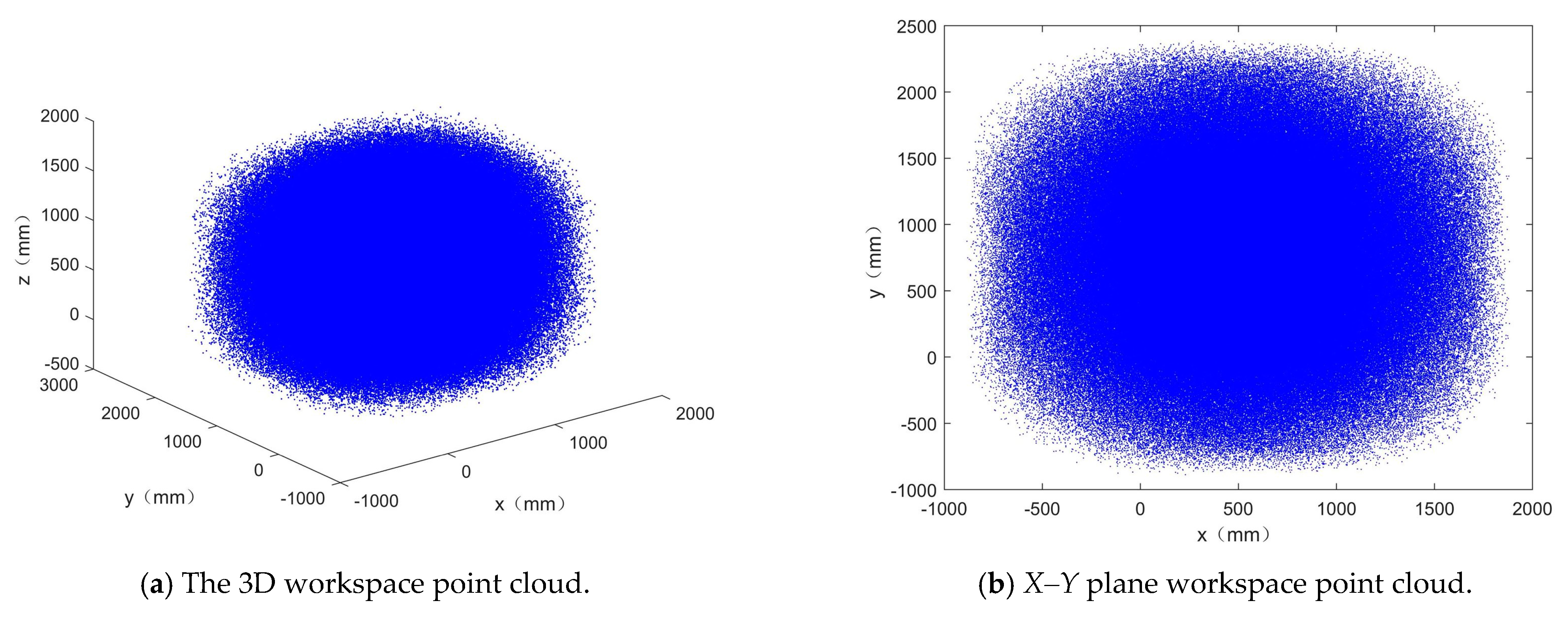
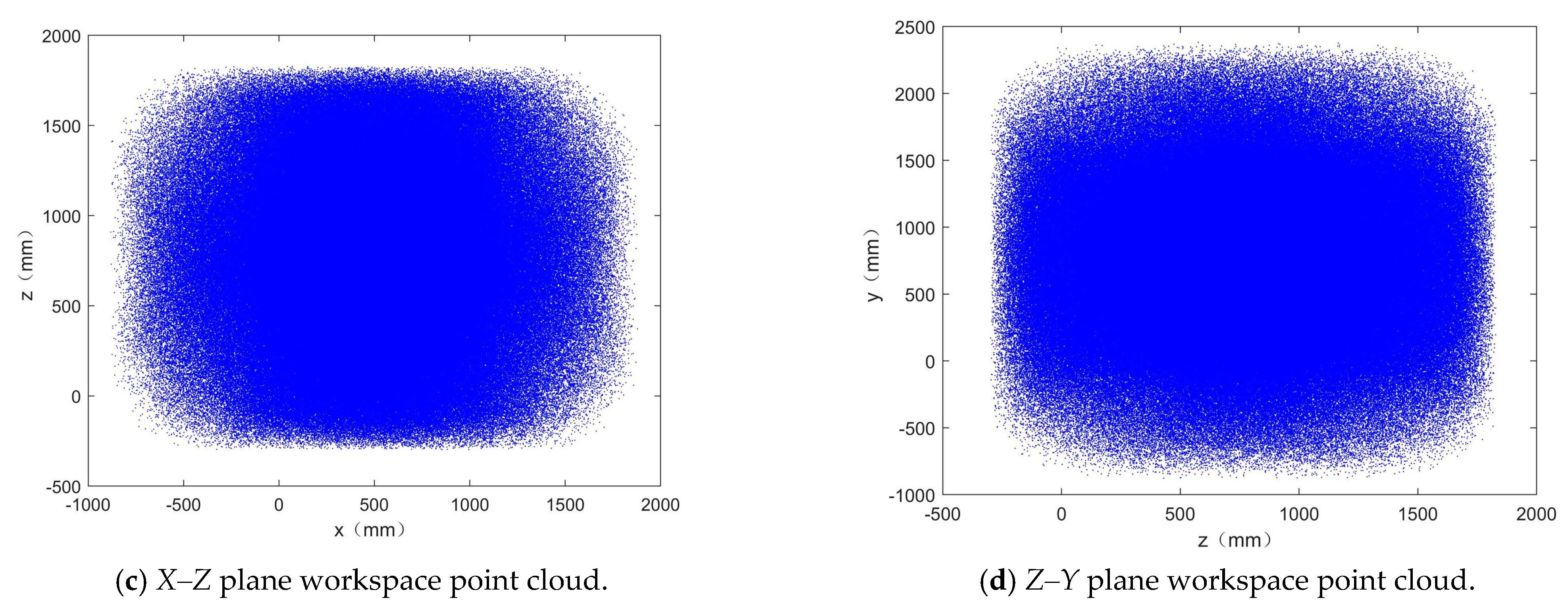
3.2.1. Workspace Verification
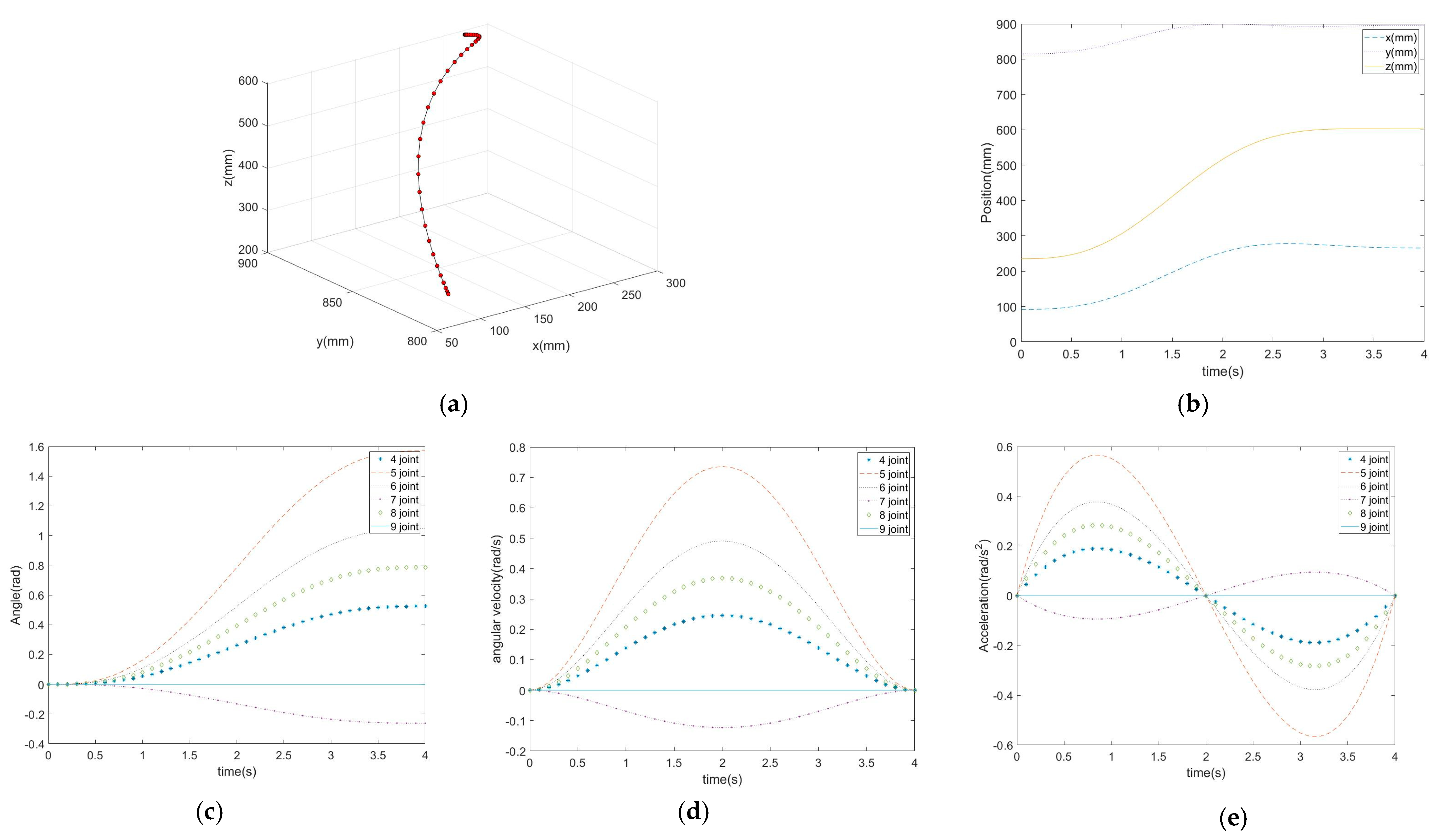
3.2.2. Motion Trajectory Simulation
4. Experimental Verification
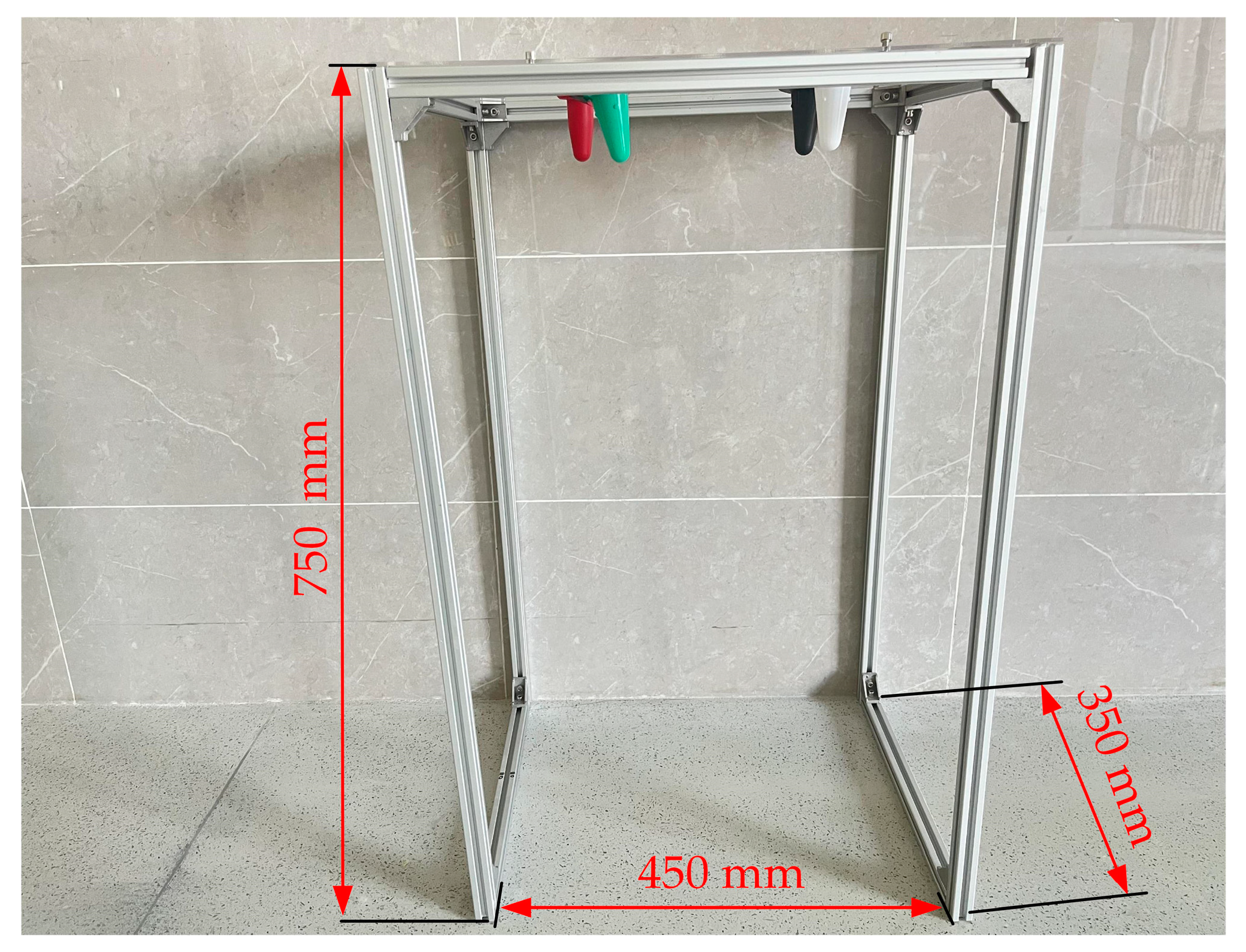
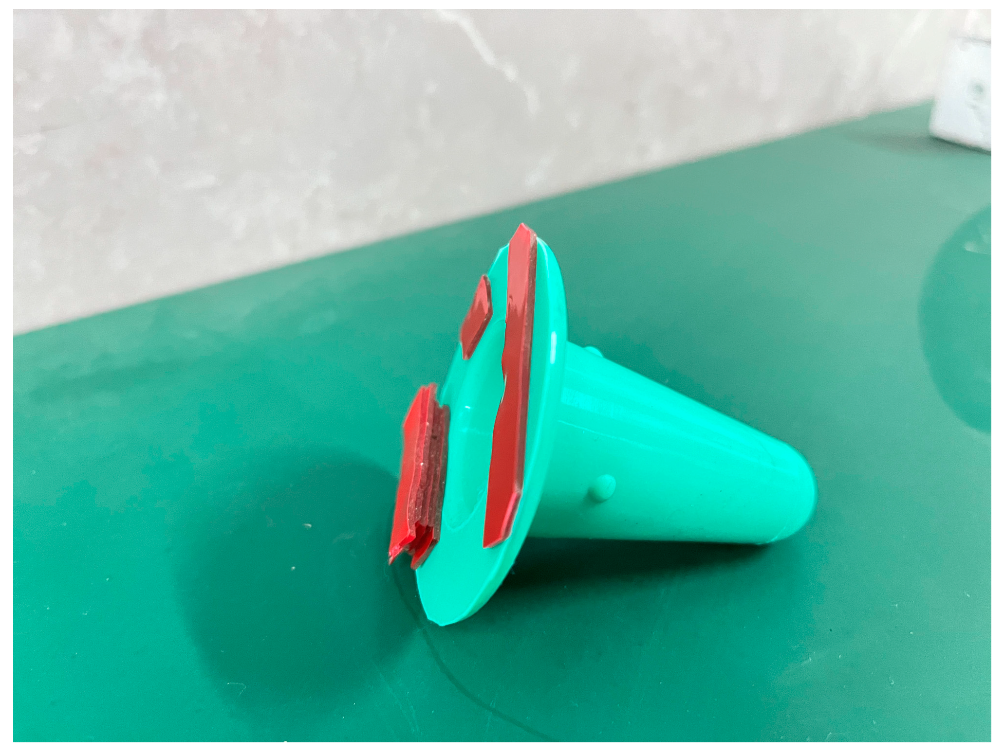
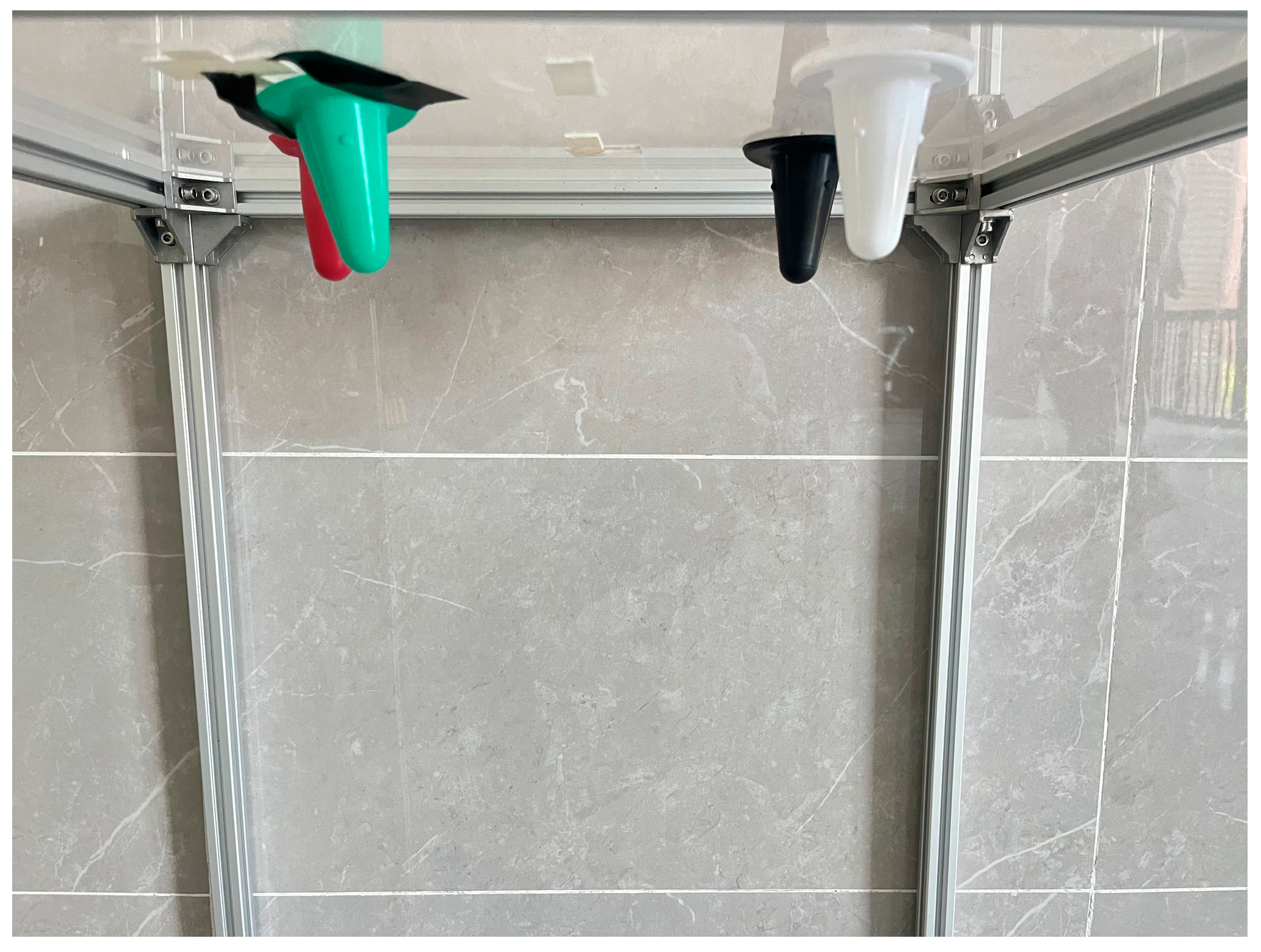
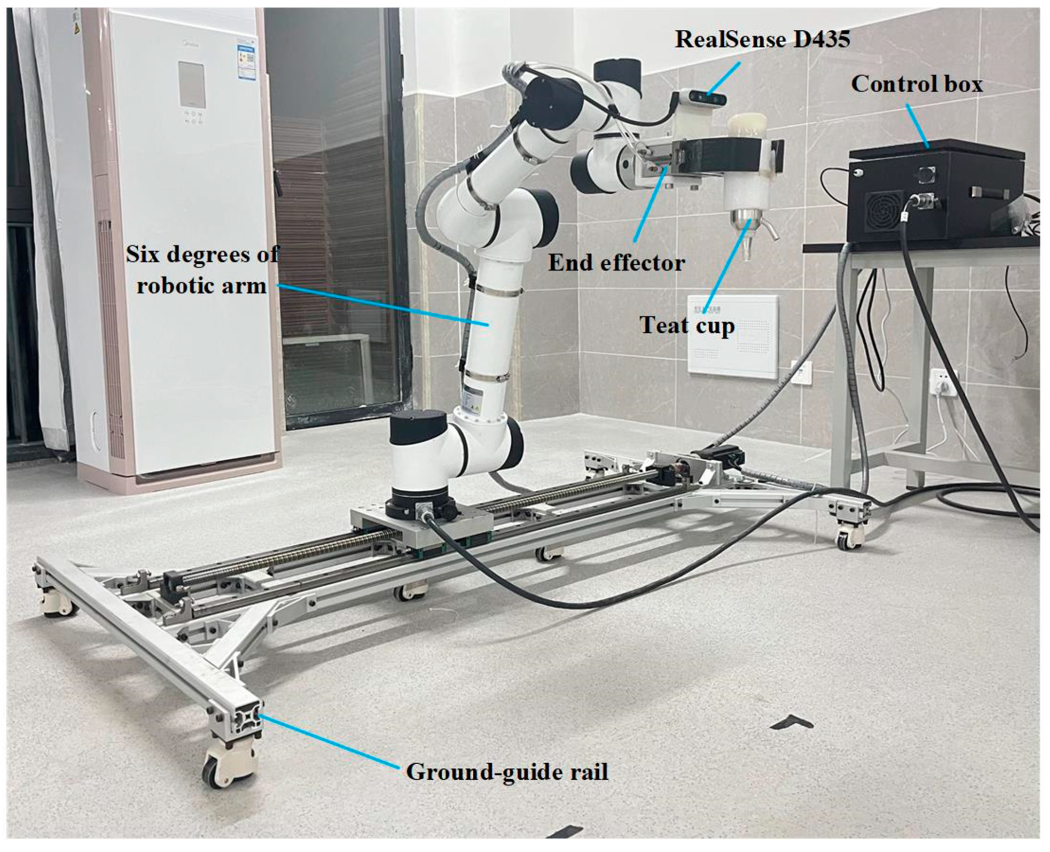
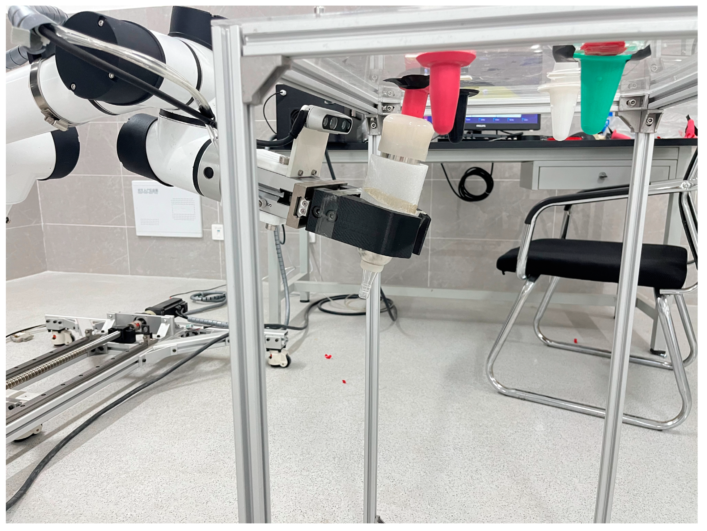
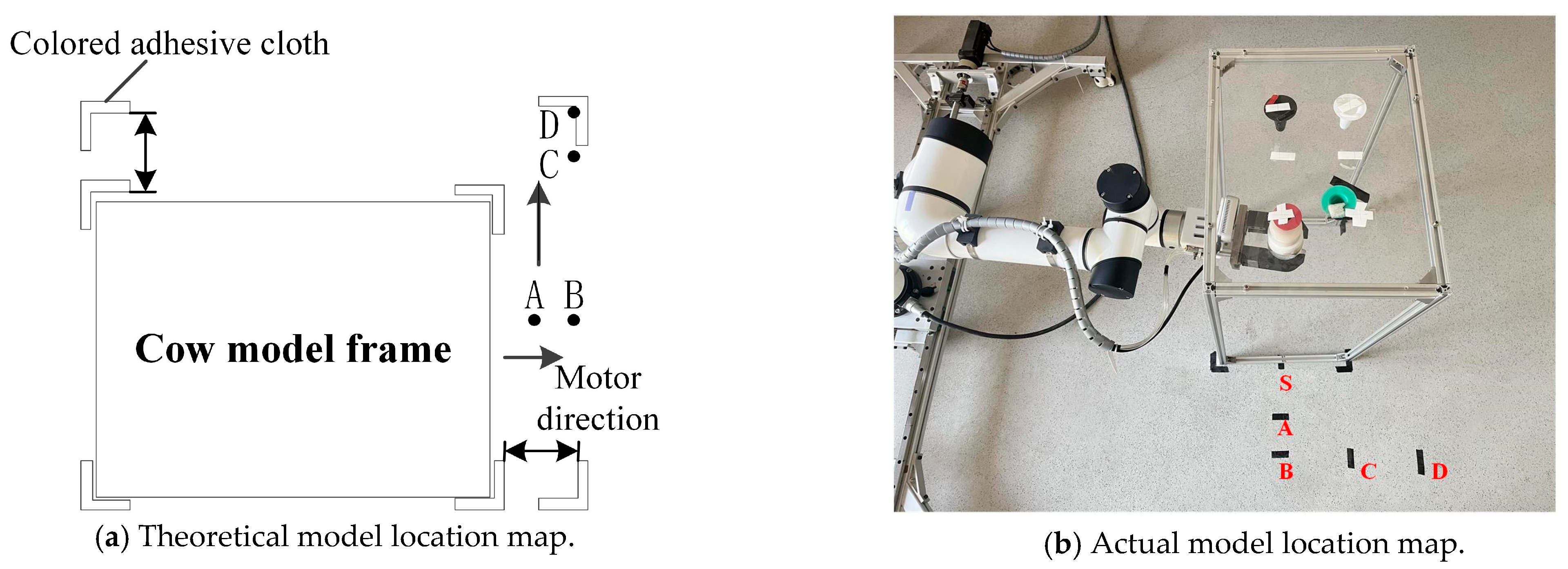
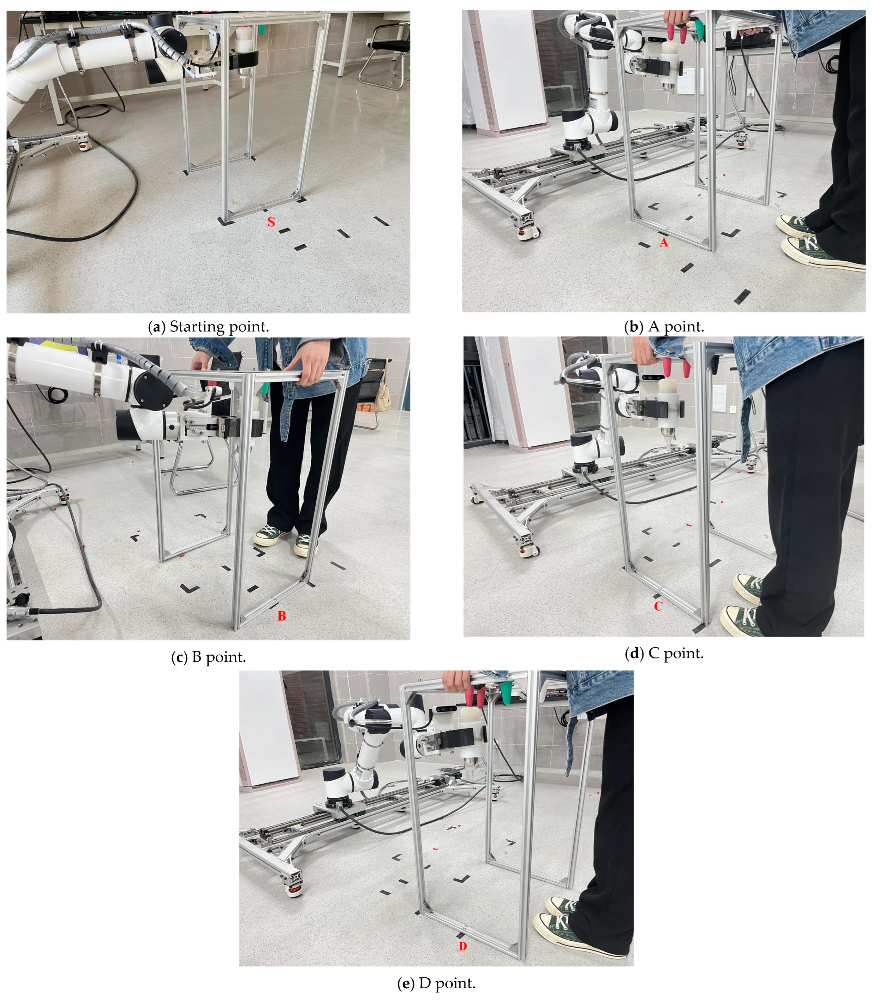
4.1. Establishment of the Experimentation Platform
4.2. Experimental Results
4.2.1. Teat Cup Attachment Error Test
4.2.2. Dynamic Response Test
5. Discussion
6. Conclusions
Author Contributions
Funding
Institutional Review Board Statement
Data Availability Statement
Conflicts of Interest
References
- Yang, Z.; Zhu, W.; Cheng, G. Dairy Market Review 2021 and Forecast 2022 trends. Chin. J. Anim. Sci. 2022, 58, 273–276. [Google Scholar] [CrossRef]
- de Koning, C.J.A.M. Milking Machines. Robotic Milking. In Encyclopedia of Dairy Sciences, 2nd ed.; Fuquay, J.W., Ed.; Academy Press: New York, NY, USA, 2011; pp. 952–958. [Google Scholar]
- Bijl, R.; Kooistra, S.; Hogeveen, H. The Profitability of Automatic Milking on Dutch Dairy Farms. J. Dairy Sci. 2007, 90, 239–248. [Google Scholar] [CrossRef] [PubMed]
- Gaworski, M. Implementation of Technical and Technological Progress in Dairy Production. Processes 2021, 9, 2103. [Google Scholar] [CrossRef]
- Rasmussen, J.B. Electricity and water consumption by milking. ICAR Tech. Ser. 2005, 10, 147–151. [Google Scholar]
- Calcante, A.; Tangorra, F.M.; Oberti, R. Analysis of electric energy consumption of automatic milking systems in different configurations and operative conditions. J. Dairy Sci. 2016, 99, 4043–4047. [Google Scholar] [CrossRef] [Green Version]
- Cogato, A.; Brščić, M.; Guo, H.; Marinello, F.; Pezzuolo, A. Challenges and Tendencies of Automatic Milking Systems (AMS): A 20-Years Systematic Review of Literature and Patents. Animals 2021, 11, 356. [Google Scholar] [CrossRef]
- Jiang, H.; Wang, W.; Li, C. Innovation, practical benefits and prospects for the future development of automatic milking systems. Front. Agric. Sci. Eng. 2017, 4, 37–47. [Google Scholar] [CrossRef] [Green Version]
- GEA DairyProQ. Available online: https://dairylane.ca/products/robotic-systems/gea-dairyproq/ (accessed on 28 December 2022).
- Zheng, G.; Shi, Z.; Teng, G. Research Progress on Facility and Equipment Technology for Dairy Farming in China. Chin. J. Anim. Sci. 2019, 55, 169–174. [Google Scholar] [CrossRef]
- Qin, H. Milking machine collection. Farm Mach. 2021, 11, 41–43. [Google Scholar] [CrossRef]
- Douphrate, D.I.; de Porras, D.G.R.; Nonnenmann, M.W.; Hagevoort, R.; Reynolds, S.J.; Rodriguez, A.; Fethke, N.B. Effects of milking unit design on upper extremity muscle activity during attachment among U.S. large-herd parlor workers. Appl. Ergon. 2017, 58, 482–490. [Google Scholar] [CrossRef]
- Frost, A.R.; Street, M.J.; Hall, R.C. The development of a pneumatic robot for attaching a milking machine to a cow. Mechatronics 1993, 3, 409–418. [Google Scholar] [CrossRef]
- Ben Azouz, A.; Esmonde, H.; Corcoran, B.; O’Callaghan, E. Development of a teat sensing system for robotic milking by combining thermal imaging and stereovision technique. Comput. Electron. Agric. 2015, 110, 162–170. [Google Scholar] [CrossRef]
- Ren, S.; He, K.; Girshick, R.; Sun, J. Faster R-CNN: Towards real-time object detection with region proposal networks. IEEE Trans. Pattern Anal. Mach. Intell. 2017, 39, 1137–1149. [Google Scholar] [CrossRef] [Green Version]
- Zheng, C.; Zhu, X.; Yang, X.; Wang, L.; Tu, S.; Xue, Y. Automatic recognition of lactating sow postures from depth images by deep learning detector. Comput. Electron. Agric. 2018, 147, 51–63. [Google Scholar] [CrossRef]
- Chu, P.; Li, Z.; Lammers, K.; Lu, R.; Liu, X. Deep learning-based apple detection using a suppression mask R-CNN. Pattern Recognit. Lett. 2021, 147, 206–211. [Google Scholar] [CrossRef]
- Zeiler, M.D.; Fergus, R. Visualizing and Understanding Convolutional Networks. In Proceedings of the Computer Vision—ECCV 2014, Cham, Switzerland, 6–12 September 2014; pp. 818–833. [Google Scholar]
- Russell, B.C.; Torralba, A.; Murphy, K.P.; Freeman, W.T. LabelMe: A Database and Web-Based Tool for Image Annotation. Int. J. Comput. Vis. 2007, 77, 157–173. [Google Scholar] [CrossRef]
- Abramov, O.; Kogan, S.; Mitnik-Gankin, L.; Sigalovsky, I.; Smirnov, A. TRIZ-based approach for accelerating innovation in chemical engineering. Chem. Eng. Res. Des. 2015, 103, 25–31. [Google Scholar] [CrossRef]
- Spreafico, C.; Russo, D. TRIZ Industrial Case Studies: A Critical Survey. Procedia CIRP 2016, 39, 51–56. [Google Scholar] [CrossRef]
- Sheu, D.-L.D.; Chiu, M.-C.; Cayard, D. The 7 pillars of TRIZ philosophies. Comput. Ind. Eng. 2020, 146, 106572. [Google Scholar] [CrossRef]
- Lin, S.Y.; Wu, C.T. Application of TRIZ inventive principles to innovate recycling machine. Adv. Mech. Eng. 2016, 8, 1687814016647303. [Google Scholar] [CrossRef] [Green Version]
- Jou, Y.-T.; Lin, W.-T.; Lee, W.-C.; Yeh, T.-M. Integrating the TRIZ and Taguchi's Method in the Optimization of Processes Parameters for SMT. Adv. Mater. Sci. Eng. 2013, 2013, 830891. [Google Scholar] [CrossRef] [Green Version]
- Bultey, A.; Beuvron, F.D.B.D.; Rousselot, F. A substance-field ontology to support the TRIZ thinking approach. Int. J. Comput. Appl. Technol. 2007, 30, 113–124. [Google Scholar] [CrossRef]
- Deng, H.; Zhu, L.; Wang, J.; Chen, M.; Wu, H.; He, C. Kinematics modeling and trajectory planning of KUKA manipulator based on MATLAB. J. Phys. Conf. Ser. 2022, 2216, 012056. [Google Scholar] [CrossRef]
- Dam, T.; Chalvatzaki, G.; Peters, J.; Pajarinen, J. Monte-Carlo Robot Path Planning. IEEE Robot. Autom. Lett. 2022, 7, 11213–11220. [Google Scholar] [CrossRef]
- Zhao, K.; Kang, Z.; Fan, H.; Rao, H.; Sun, W.; Wang, J.; Lai, S. Correlation Research between Anogenital Distance and Milk Production in Chinese Holstein Dairy Cattle. J. Sichuan Agric. Univ. 2022, 40, 645–648. [Google Scholar] [CrossRef]
- Gao, J.; Li, C.; Pang, J.; Peng, Y.; Sun, L.; Yu, F. Development and application of 9JZP-80 high efficiency rotary milking machine. Heilongjiang Anim. Sci. Vet. 2022, 648, 50–55. [Google Scholar] [CrossRef]
- Zhao, J.; Han, T.; Ma, X.; Ma, W.; Liu, C.; Li, J.; Liu, Y. Research on Kinematics Analysis and Trajectory Planning of Novel EOD Manipulator. Appl. Sci. 2021, 11, 9438. [Google Scholar] [CrossRef]
- Li, K.; Huo, Y.; Liu, Y.; Shi, Y.; He, Z.; Cui, Y. Design of a lightweight robotic arm for kiwifruit pollination. Comput. Electron. Agric. 2022, 198, 107114. [Google Scholar] [CrossRef]
- Zhu, H. Effect on Milking Performance Parameters and Cow Udder Health Between Rubber Liner and Silicone Liner. Master’s Thesis, Nanjing Agricultural University, Nanjing, China, 2019. [Google Scholar] [CrossRef]
- Gemini—Double Box Milking. Available online: https://boumatic.com/us_en/products/gemini-the-boumatic-milking-robot-1-1-1/ (accessed on 22 April 2023).
- Kolbach, R.; Kerrisk, K.; Garcia, S. Short communication: The effect of premilking with a teat cup–like device, in a novel robotic rotary, on attachment accuracy and milk removal. J. Dairy Sci. 2013, 96, 360–365. [Google Scholar] [CrossRef]


| Deterioration Parameter | No. 36: Complexity of the Equipment | |
|---|---|---|
| Improved Parameter | ||
| No. 07: The volume of the moving object | 26, 01 | |
| No. 26: The quantity of the substance | 03, 13, 27, 10 | |
| i | αi-1 | ai-1/mm | di/mm | θi | Range of Variables |
|---|---|---|---|---|---|
| 1 | −90° | 0 | d1 | 0 | 0~1500 mm |
| 2 | 90° | 0 | d2 | 90° | 300~1500 mm |
| 3 | 90° | 0 | d3 | 0 | 0~1000 mm |
| 4 | 90° | 0 | d4 (135) | θ4 | −175~175° |
| 5 | −90° | a5 (421) | 0 | θ5 | −175~175° |
| 6 | 0 | a6 (394) | 0 | θ6 | −175~175° |
| 7 | 0 | 0 | d7 (92) | θ7 | −175~175° |
| 8 | −90° | 0 | d8 (70) | θ8 | −175~175° |
| 9 | −90° | 0 | 0 | θ9 | −360~360° |
| Parameter | CPU | RAM | CPU Clock Speed | Hard Disk Drive | Real-Time System | Operating System | Jitter Delay |
|---|---|---|---|---|---|---|---|
| Data | i7-4500 U | 8 GB | 2.6 GHz | 128 GB SSD | Support | Ubuntu16.04 LTS + Xenimai | 30 μs |
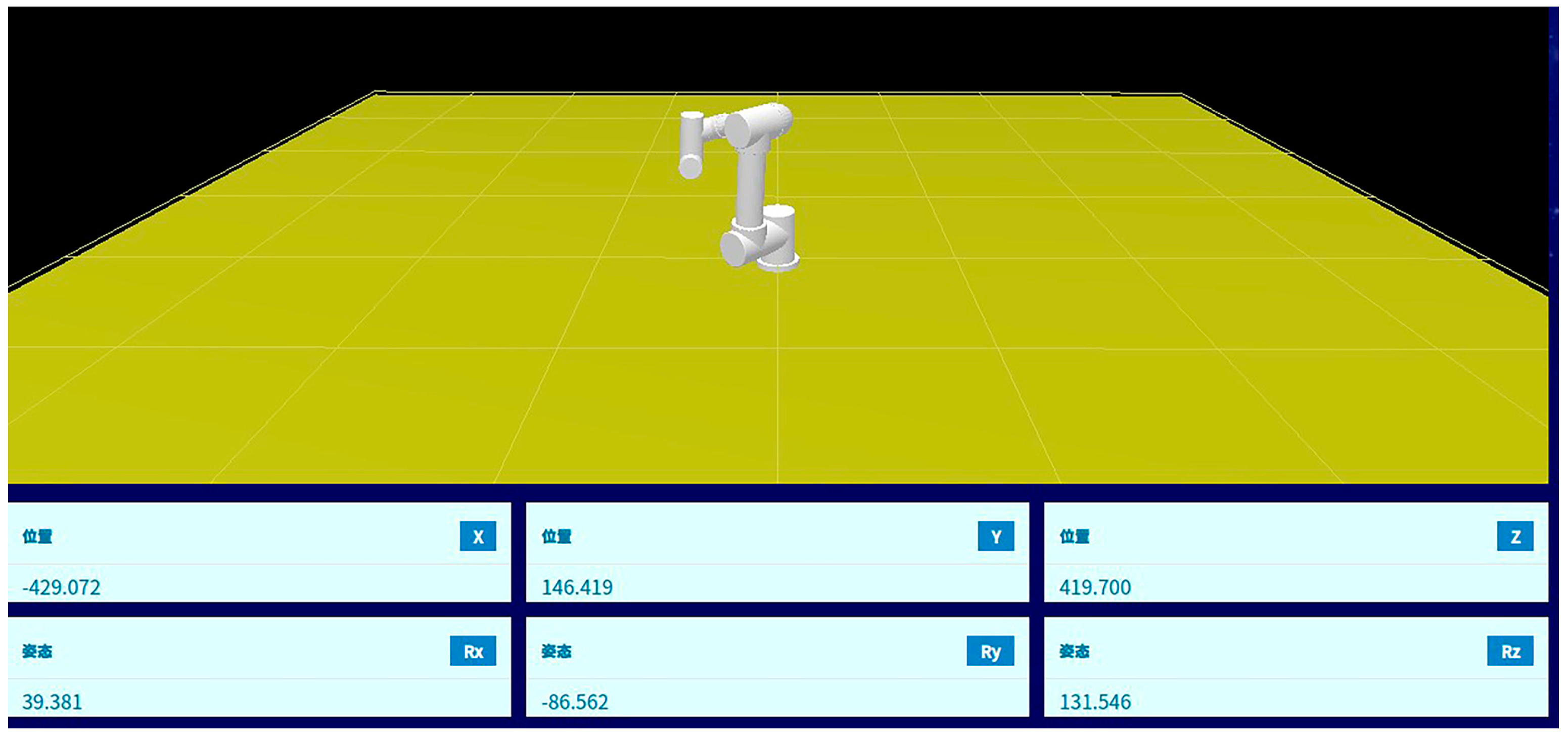
| End Pose Coordinates | x/mm | y/mm | z/mm | Rx/° | Ry/° | Rz/° |
|---|---|---|---|---|---|---|
| Teat 1 | −429.072 | 146.419 | 419.700 | 39.381 | −86.562 | 131.546 |
| Teat 2 | −421.632 | 156.815 | 419.301 | 54.385 | 73.251 | 143.704 |
| Teat 3 | −429.225 | 147.105 | 420.427 | 63.508 | −69.724 | 120.463 |
| Teat 4 | −430.354 | 155.250 | 420.708 | 35.564 | −93.552 | 152.107 |
| End Pose Coordinates | x/mm | y/mm | z/mm | Rx/° | Ry/° | Rz/° | Max Error (mm/°) |
|---|---|---|---|---|---|---|---|
| Teat 1 | −429.537 | 146.921 | 420.655 | 39.542 | −85.935 | 131.904 | 0.955/0.627 |
| Teat 2 | −422.792 | 156.987 | 420.352 | 55.236 | -72.914 | 142.807 | 1.160/0.897 |
| Teat 3 | −430.850 | 146.234 | 421.059 | 63.932 | −70.318 | 119.832 | 1.625/0.631 |
| Teat 4 | −431.106 | 156.021 | 419.589 | 36.781 | −94.534 | 151.863 | 1.119/1.216 |
| Coordinate Value | X/mm | Y/mm | X1/mm | Y1/mm |
|---|---|---|---|---|
| Starting point | 0 | 0 | 0 | 0 |
| A point | 50 | 0 | 50.725 | 0.725 |
| B point | 100 | 0 | 100.189 | 1.811 |
| C point | 100 | 50 | 102.016 | 53.675 |
| D point | 100 | 100 | 101.507 | 99.206 |
Disclaimer/Publisher’s Note: The statements, opinions and data contained in all publications are solely those of the individual author(s) and contributor(s) and not of MDPI and/or the editor(s). MDPI and/or the editor(s) disclaim responsibility for any injury to people or property resulting from any ideas, methods, instructions or products referred to in the content. |
© 2023 by the authors. Licensee MDPI, Basel, Switzerland. This article is an open access article distributed under the terms and conditions of the Creative Commons Attribution (CC BY) license (https://creativecommons.org/licenses/by/4.0/).
Share and Cite
Wang, C.; Ding, F.; Ling, L.; Li, S. Design of a Teat Cup Attachment Robot for Automatic Milking Systems. Agriculture 2023, 13, 1273. https://doi.org/10.3390/agriculture13061273
Wang C, Ding F, Ling L, Li S. Design of a Teat Cup Attachment Robot for Automatic Milking Systems. Agriculture. 2023; 13(6):1273. https://doi.org/10.3390/agriculture13061273
Chicago/Turabian StyleWang, Chengjun, Fan Ding, Liuyi Ling, and Shaoqiang Li. 2023. "Design of a Teat Cup Attachment Robot for Automatic Milking Systems" Agriculture 13, no. 6: 1273. https://doi.org/10.3390/agriculture13061273