4.1. Design of Pulling Device
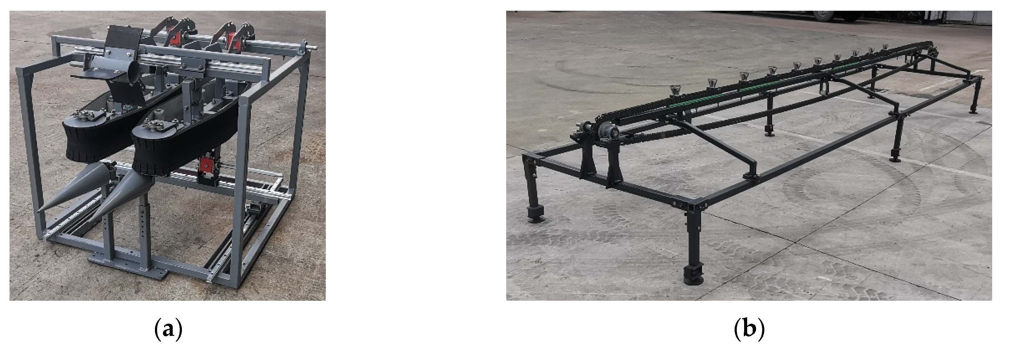
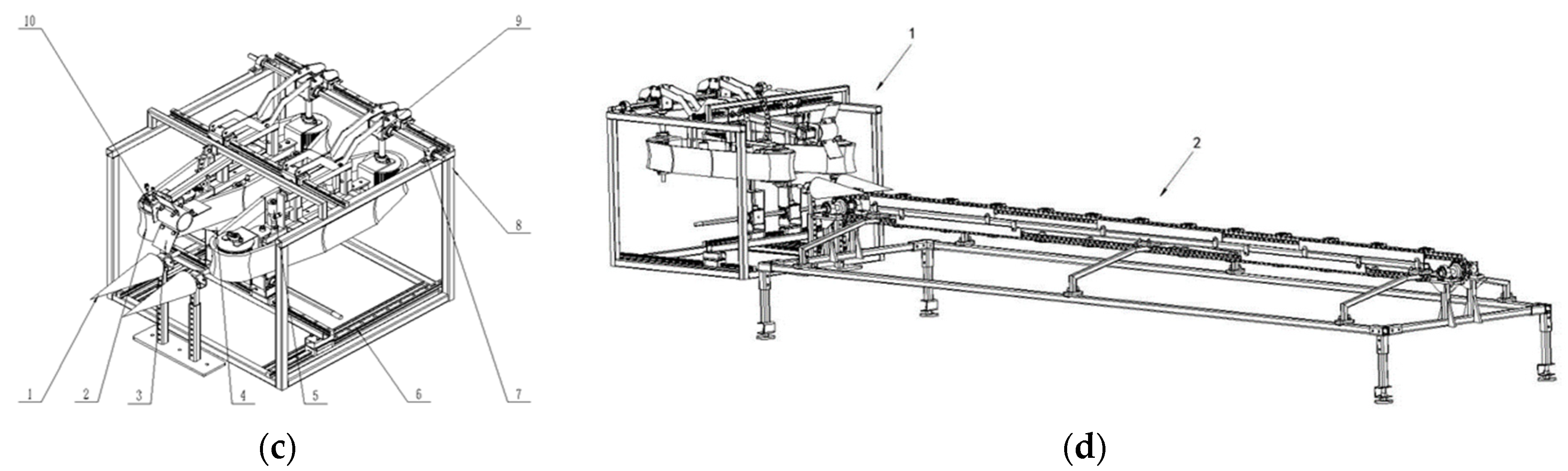
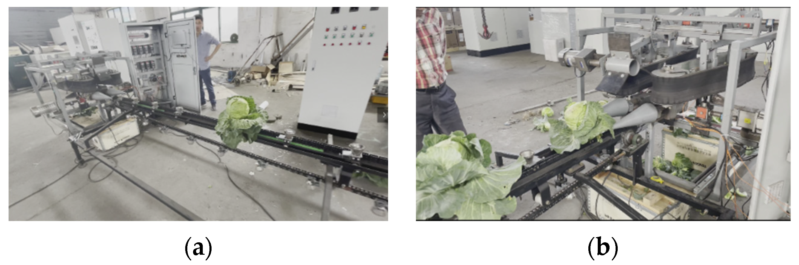
As shown in
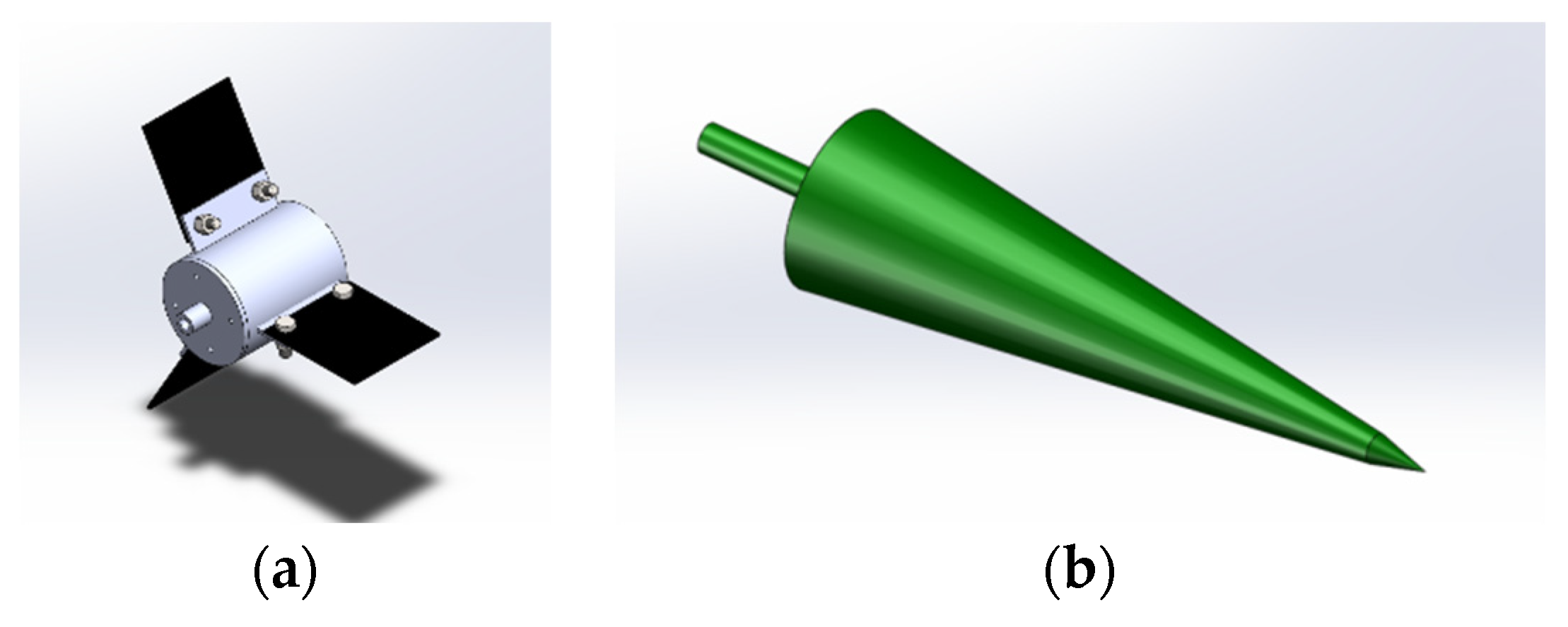
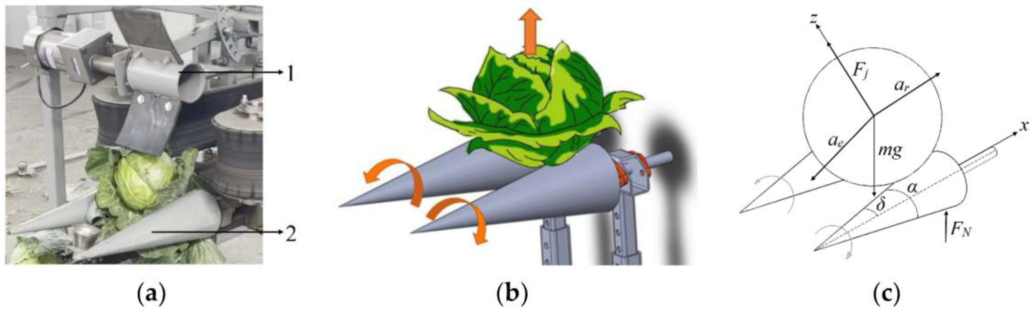
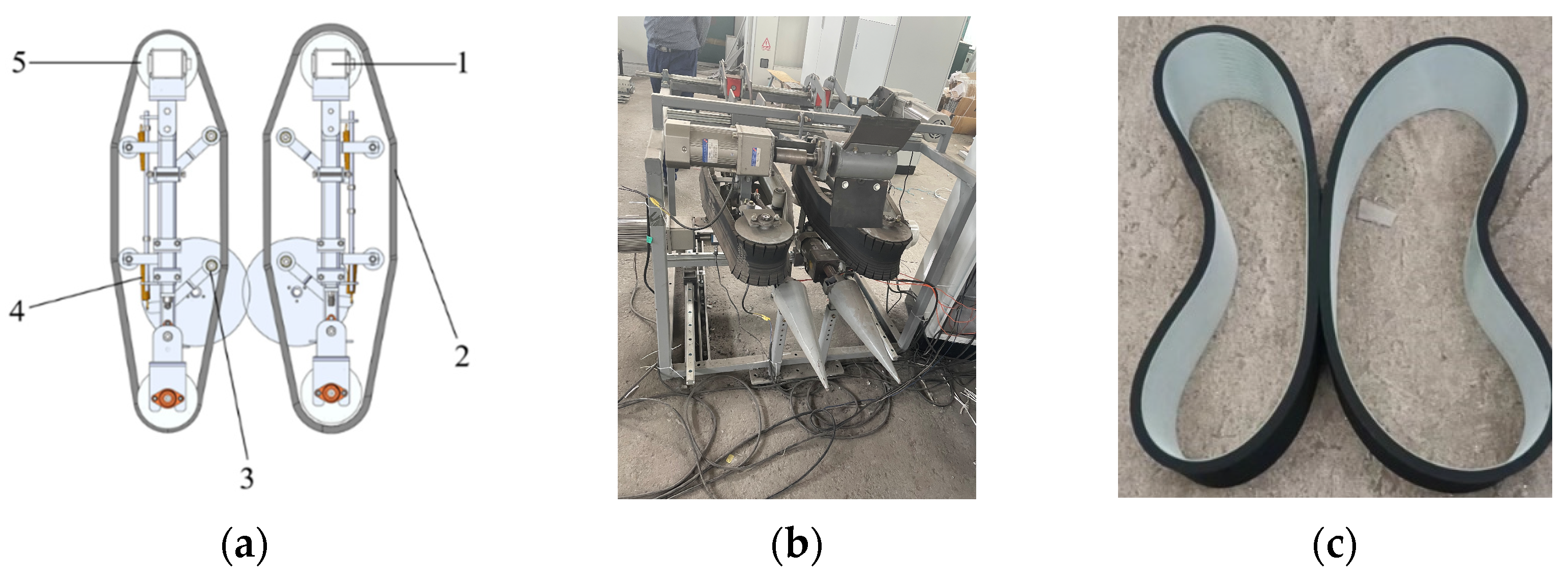
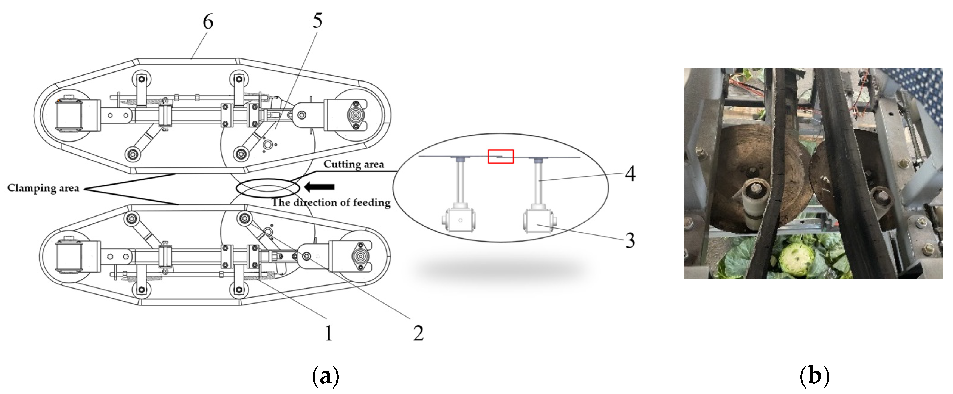
Figure 5a,b, the pulling device of the test platform is mainly composed of a reel and a pulling roller. When the pulling device works, the pulling roller is located below the cabbage. Through their own continuous external rotation, the cabbages are subjected to an upward pulling force. After the root of the cabbage is completely separated from the conveying system, it enters the clamping conveying mechanism through the right position of the reel above the pulling roller.
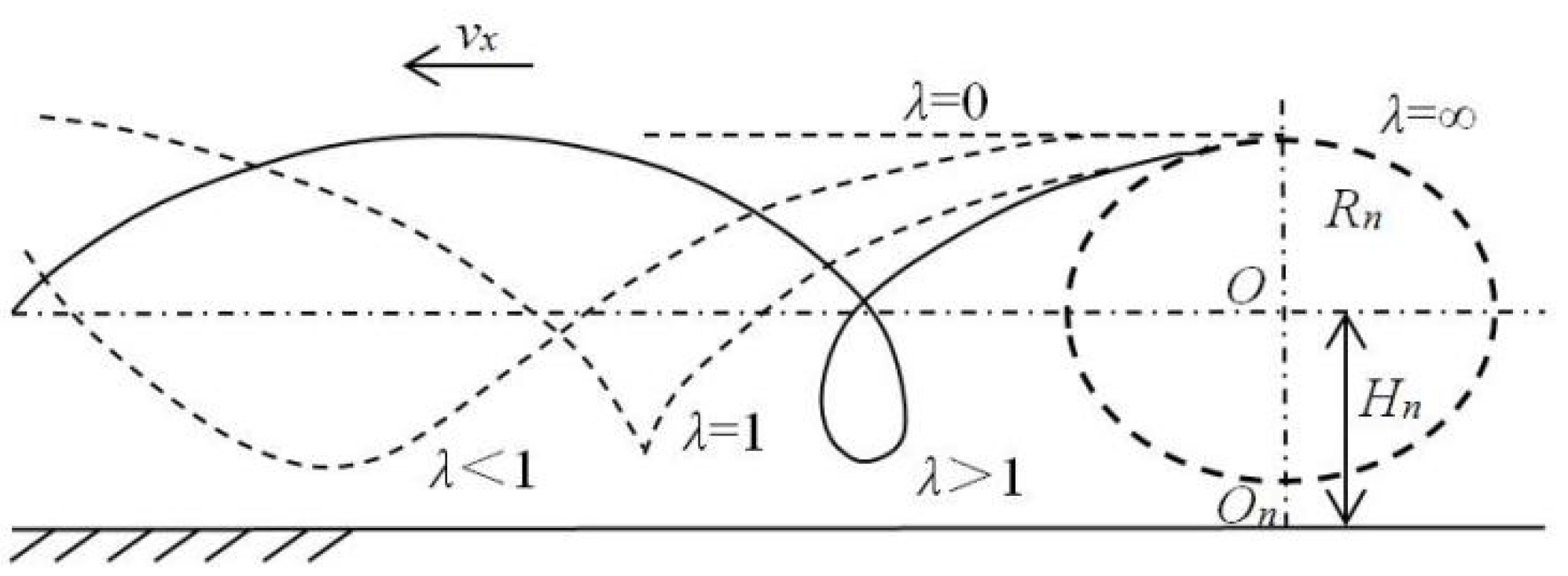
As shown in Formula (1), the ratio of the linear velocity at the outer edge of the reel to the forward speed of the machine is called the reeling speed ratio
λ. When
λ ≤ 1, the cycloid amplitude of the working trajectory of the reel is small, and the function of supporting and guiding the cabbage cannot be realized. As shown in
Figure 6, when λ > 1, the working trajectory of the reel is cycloidal. At this time, the reel can work normally, and the reel effect works well.
where
V0 is the speed along the outer line when the wheel is working, m/s, and
Vx is the conveying speed of cabbage.
The displacement equation for the reel:
where
Rn is the radius of the reel, mm, and
Wn is the rotation speed of the reel, r/min.
Hn is the height from the center of the reel to the ground, mm.
It is assumed that the reel has “m” reel leaves. When a reel leaf rotates one circle, the forward distance of the harvester is:
where
L is the forward distance of the harvester, m, and
Vn is the angular velocity of the reel, rad/s.
When the reel works normally, the size of the reel should meet:
where
D is the diameter of the cabbage.
In order to achieve continuous harvesting, the pitch of the long trochoid of the reel should meet:
where
Sn is the pitch of the long trochoid of the reel;
Sl is the distance between two adjacent cabbages; and
n is the reel leaf spacing, generally taking 1, 2, and 3.
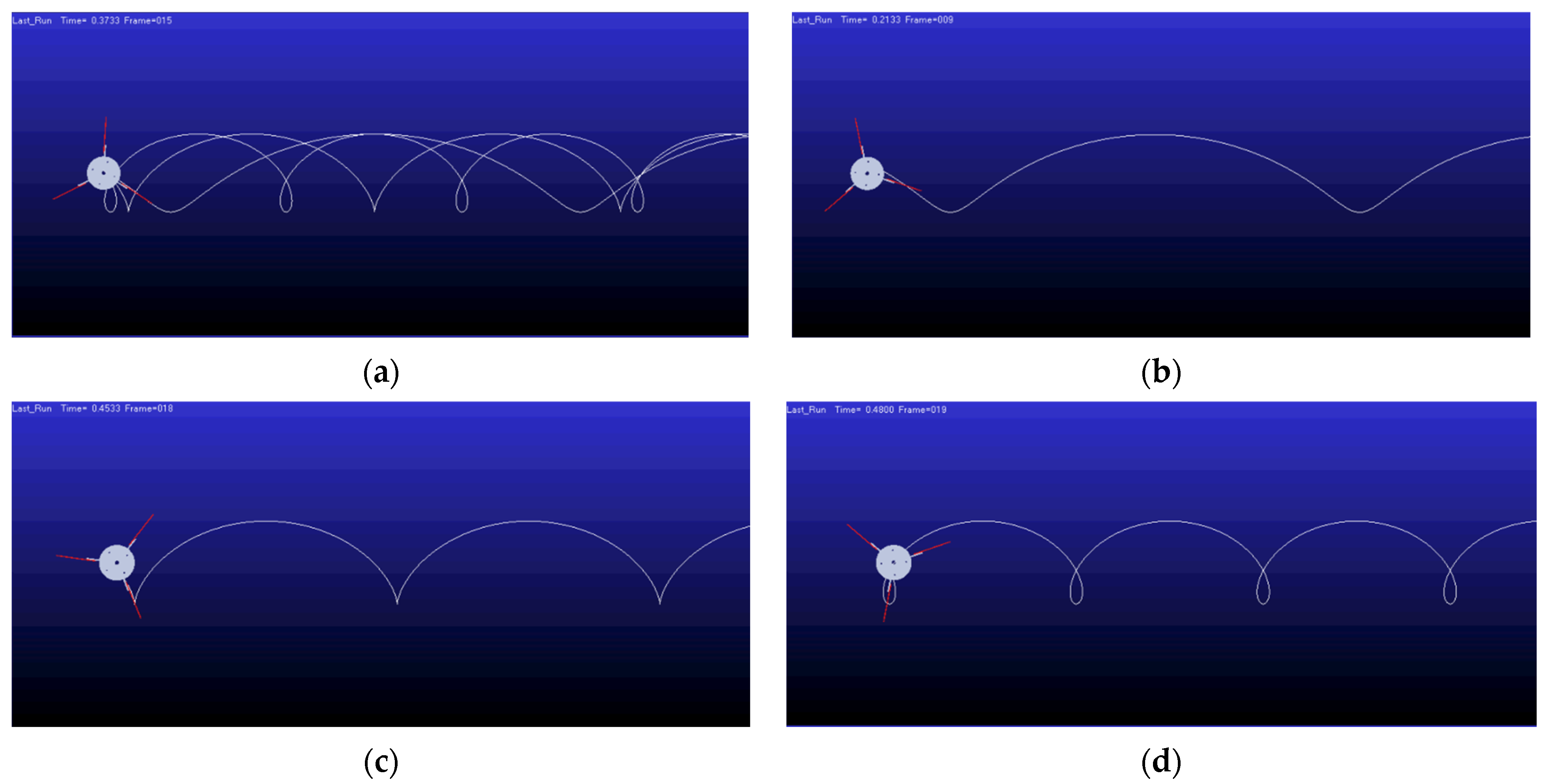
The number of reel leaves on the test platform is 3, the radius of the reel is 240 mm, the distance of cabbage in the conveying system is 350 mm, take 1 for
n, and the conveying speed of the conveying system is set to be 0.3 m/s. The rotation speed of the reel is set to 30, 50, or 70 r/min, and the trajectory of the reel is simulated by MATLAB-ADAMS. The simulation trajectory is shown in
Figure 7.
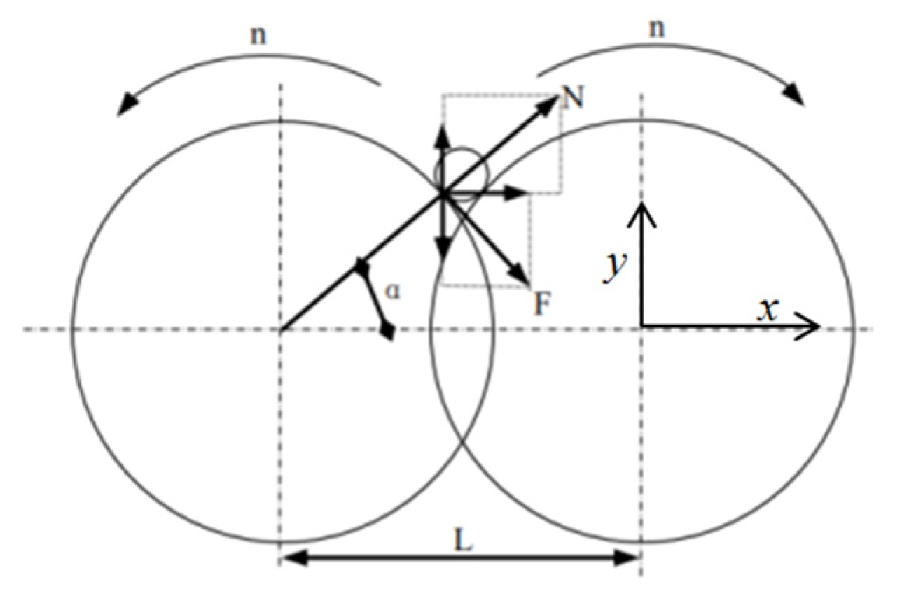
4.2. Design of Pulling Roller
In order to analyze the movement of the cabbage on the pulling roller, the cabbage and the pulling roller are formed into a rigid body system for force analysis. In order to simplify the model, the position of the mass center is not considered in the analysis process. See
Figure 8.
According to the centroid motion law of rigid body motion, the force balance equations in the
x-direction and
z-direction are listed:
From the above formula, it can be deduced that:
The conditions that must be met to make the cabbages move upwards without falling are:
αr > 0. It can be derived from Formulas (8) and (12):
where
μ is the friction coefficient of cabbage;
Fm is the overall force of the pulling roller on the cabbage, N;
αr is the relative acceleration of the motion of the cabbage, in m/s
2;
αe is the acceleration of the conveying system, in m/s
2;
δ is the angle between the cone on the pulling roller and the horizontal line, (°);
Fj is the pull-out force of the pull-out roller on cabbage, N;
αj is the absolute acceleration of the conveying system, in m/s
2;
mj is the weight of a single pulling roller, in kg;
Fn is the friction force between cabbage and the pulling roller, N; and
Km is the mass ratio of the pulling roller with cabbage.
To ensure that the cabbages do not fall during harvest, it is necessary to meet Formula (14). Therefore, the material properties should be considered when designing the pulling roller. It can be seen from Formula (12) that the relative motion between the pulling roller and the cabbage has a great influence on transportation, so the rotation speed of the pulling roller plays a vital role in the qualified rate of harvesting.
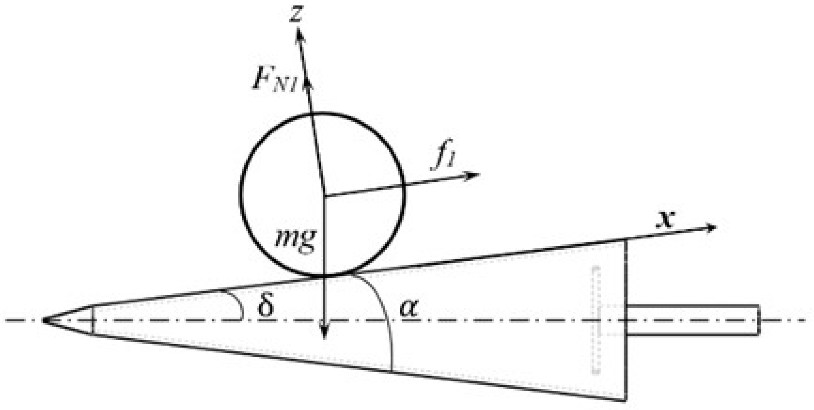
As shown in
Figure 9, the force analysis of cabbage in the pulling process is carried out.
where
f1 is the resistance and friction of the cabbage in the pulling process, N;
FN1 is the supporting force of the working surface of the pulling roller on the cabbage, N; and
α is the pulling angle of the pulling roller, (°).
When the cabbage is pulled out, it is subjected to resistance, friction, and support. After overcoming gravity, the pull-out force of cabbage is:
It can be derived from Formulas (15)–(17):
The weight of cabbage is determined by
Table 1 at 1.91 kg. According to Formula (19), the pulling force
F of the pulling roller on cabbage depends on the pulling angle α. Therefore, a better pulling effect can be obtained by selecting the appropriate pulling angle. The material of the pulling roller designed in this paper is stainless steel, the friction coefficient is 0.3, the distance between the inside of the pulling roller is 50–80 mm, the diameter of the end is 120 mm, the total length of the conical pulling roller is 450 mm, and the angle between the pulling roller (taper) and the horizontal angle is 13.9°. At this time, the pulling force of the two pull-out rollers on cabbage is:
At this time, the theoretical pulling force of the pulling roller designed in this paper is greater than the pulling force measured in
Table 2, which meets the design requirements.
Figure 9.
Pulling force analysis.
Figure 9.
Pulling force analysis.
4.3. Design of Clamping Conveying Device
As shown in
Figure 9, the low-loss harvesting test platform for cabbage designed in this paper adopts a new mechanism and new method called “vertical clamping + flexible conveying”. By using the flexible feeding and flexible clamping methods, we can improve the adaptability of different ball diameters of cabbage and realize low-loss transportation [
22,
23].
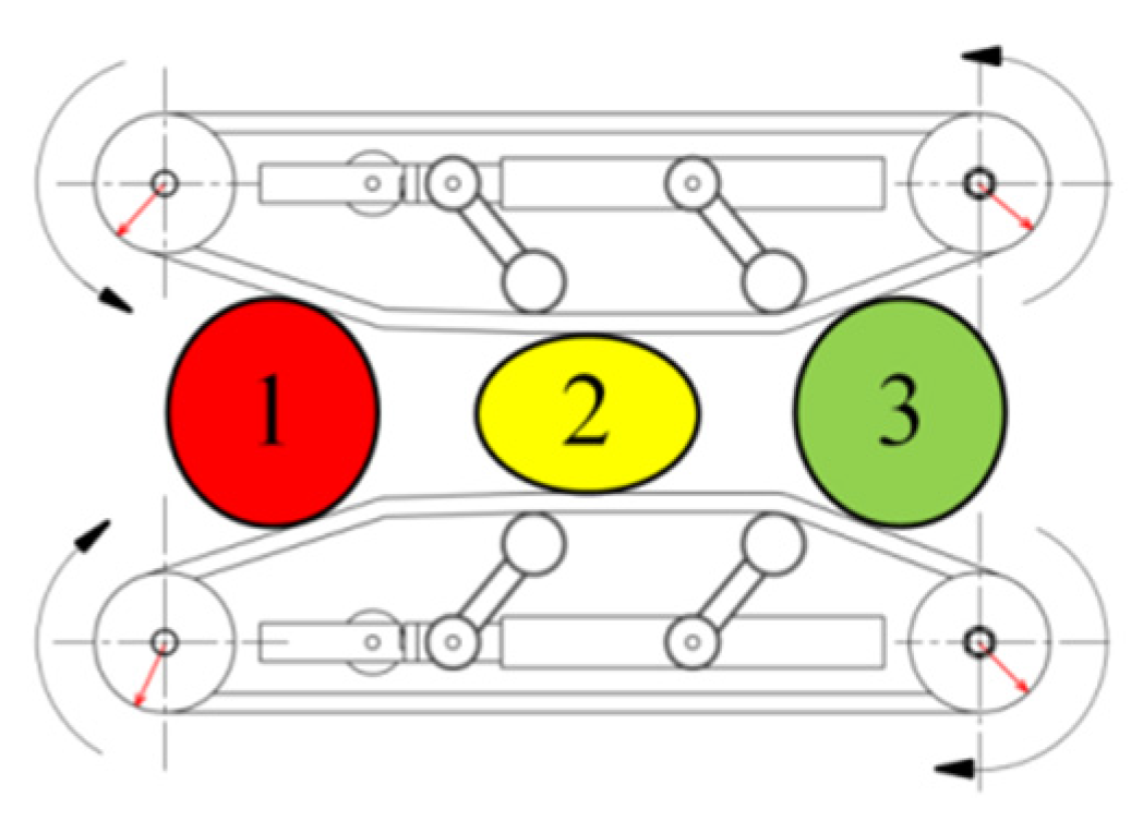
The analysis of the movement process of the cabbage in the clamping and conveying device is shown in
Figure 10, where 1 is the cabbage feeding link, 2 is the clamping and conveying link, and 3 is the harvesting of the finished product link.
The clamping conveying process of cabbage is shown in
Figure 11.
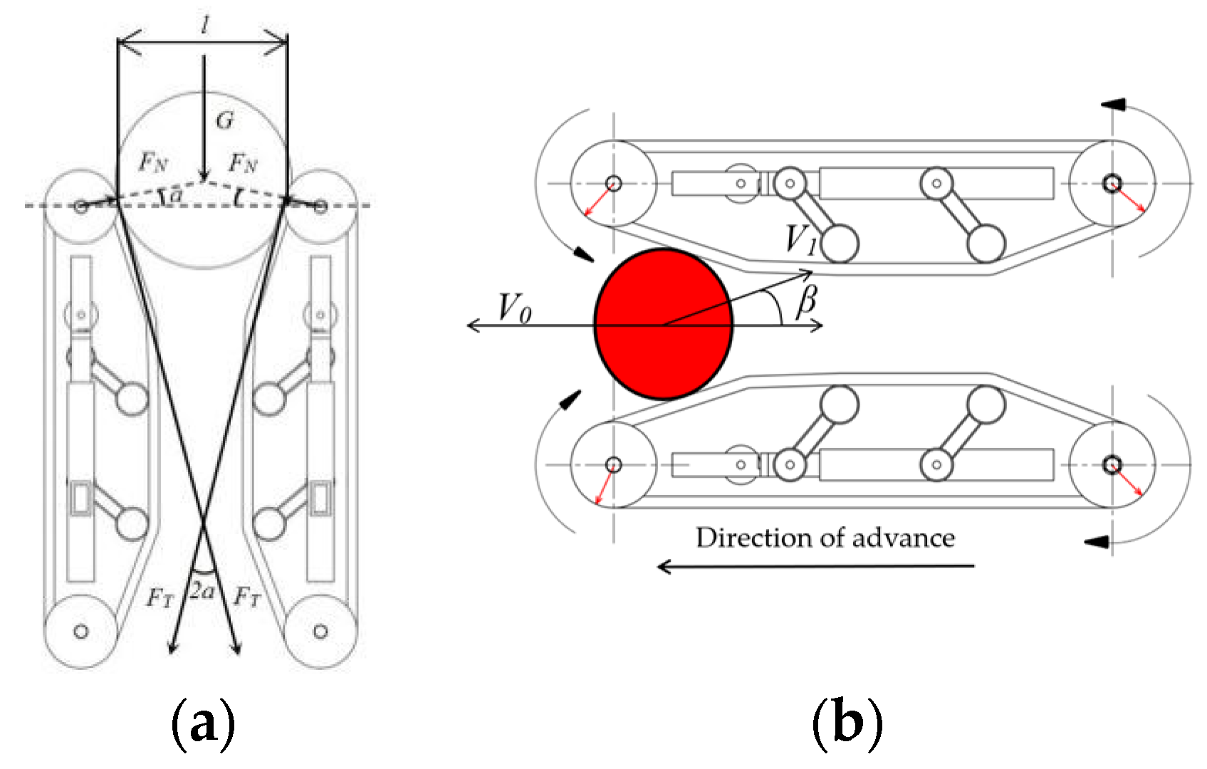
The motion analysis and force analysis of the feeding link of the cabbage are shown in
Figure 12a,b.
If the cabbages are not blocked in the feeding link and smoothly enter the clamping and conveying link, the following formula should be satisfied:
According to the above formula, it can be calculated by the following formula:
where
α is the angle between pressure and the horizontal line of cabbage;
V1 is the linear velocity of the conveyor belt, m/s;
β is the lifting angle of the conveyor belt, (°);
V0 is the operating speed of the conveying system, m/s;
FT is the friction force on cabbage, N;
FN is the pressure of the conveyor belt on cabbages, N;
μ is the friction coefficient between the conveyor belt and cabbages;
D is the diameter of the conveyor belt drive wheel, mm;
d is the diameter of cabbage, mm; and
l is the distance between the two conveyor belt drive wheels, mm.
The feeding inlet clamping position of the conveyor belt should be at the waist of the cabbage. In this paper, the single weight of “Chun xi” cabbage was 1.2–1.5 kg, the bulb was 180–200 mm, the feeding inlet spacing of the clamping conveying mechanism, which can be adjusted by spring and the minimum spacing, was 120 mm, and the diameter of the conveyor belt drive wheel was 110 mm. Therefore, the maximum value of the friction coefficient between the conveyor belt and the cabbage can be calculated as follows:
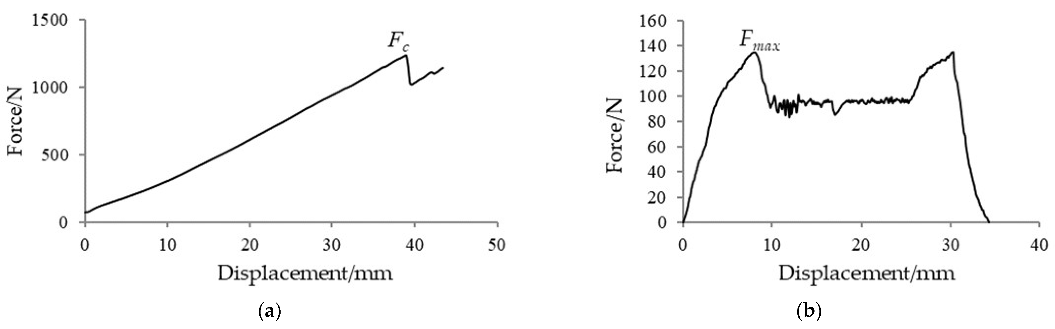
The maximum extrusion force of cabbage is:
According to the test of the mechanical harvesting characteristics of the cabbage, the extrusion force is far less than the maximum extrusion crushing force of 1198.4 N. Based on the compressional force test results, the clamping and conveying mechanical structure designed in this paper can avoid the results that the cabbage cannot be clamped due to too small extrusion pressure, and if the extrusion pressure is continuously increased, the cabbage may be blocked, so the structural parameters of the clamping and conveying device are designed reasonably.
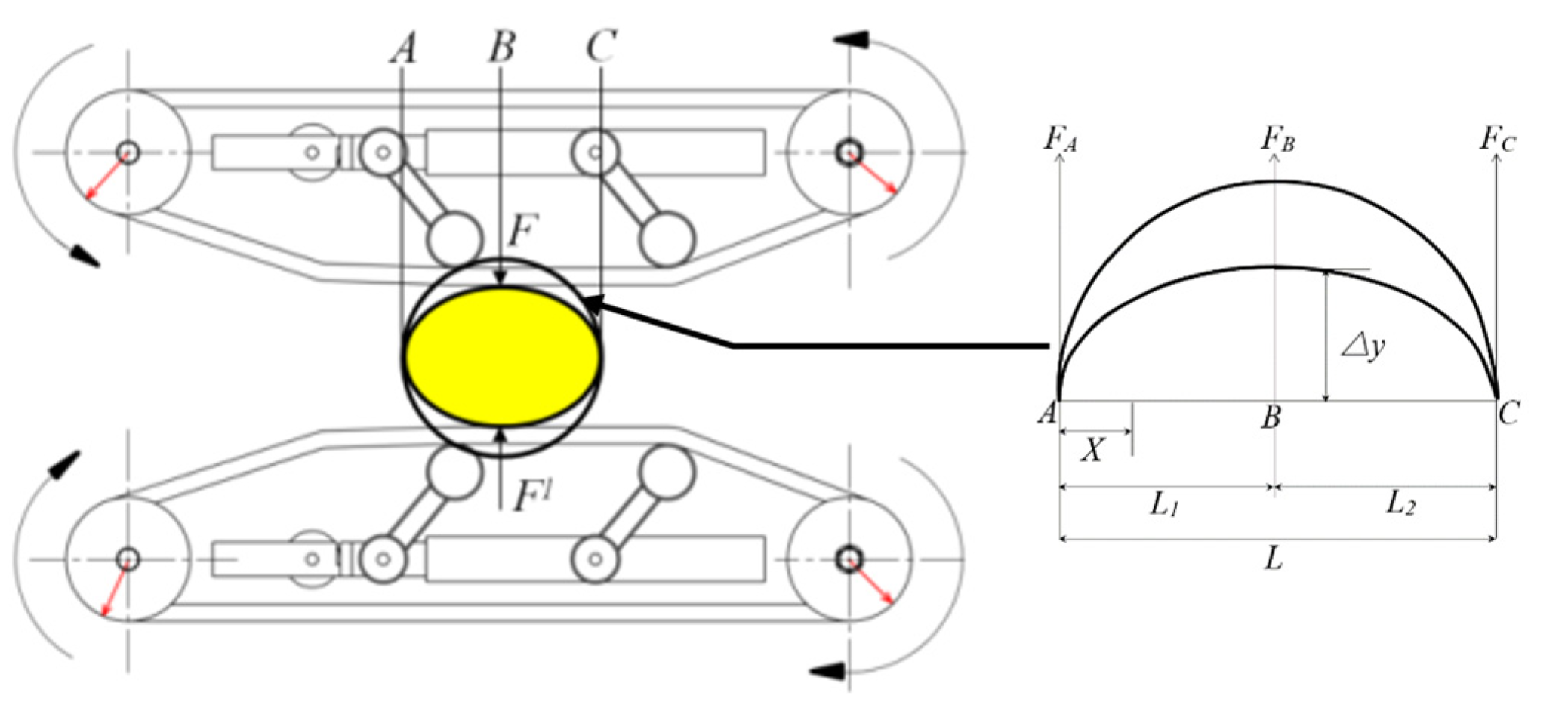
By analyzing the force on the base surface of the conveying interval and the deformation of the cabbage [
24], the deformation analysis in the extrusion deformation link is shown in
Figure 13.
It can be seen from
Figure 12 that the extrusion force
F =
F1 at point B and the forces
FA and
FC at points
A and
C are:
The reaction force of point
B can be obtained from the equilibrium equation:
The deformation bending moment of cabbage is:
The deformation-bending moment is the same on both sides, and the integral on one side can be obtained:
The deflection curve equation is:
Because
x =
L1 =
L2, the clamping deformation ∆
y of cabbage is:
where
E is the modulus of elasticity;
J is the momentum of inertia;
L is the length of
AC, mm;
L1 is the length of
AB, mm; and
L2 is the length of
BC, mm.
According to Formula (15), when the conveyor belt speed is too low, the conveying efficiency will be reduced, which makes it easy to cause conveying blockage, resulting in unsmooth subsequent operations and incomplete root cutting. Through the preliminary test and observation, the main forms of damage in the transportation of cabbages are friction, extrusion, collision, and other forms of damage. The reason is that the deformation of cabbage is too large under the action of rigid parts in the conveying process. If the deformation deflection ∆y of cabbage is too large, it is easy to squeeze and break. In Formula (25), the deformation deflection of the cabbage is determined by the elastic modulus. In order to reduce the damage as much as possible, the high-density CR flexible sponge belt is selected to wrap the cabbage for clamping and conveying. While reducing the relative friction, the tensioning mechanism transfers part of the deformation of the cabbage to the flexible clamping conveyor belt. It has a certain anti-deformation effect on the cabbages and can ensure that the cabbages do not slide when they are clamped by the conveyor belt and will not cause ineffective root cutting of the cabbage due to sliding.
In order to adapt to different kinds of cabbage and improve the adaptability of harvesting equipment. The maximum center spacing of the conveyor belt designed in this paper can be adjusted to 280 mm, and the feeding inlet spacing can be adjusted in the range of 200–250 mm. Ensure that different varieties of cabbage can be successfully clamped and transported, even if the ball diameter is different.
4.4. Design of Root Cutting Device
The root-cutting device is one of the key components of the cabbage harvester. It works together with the clamping and conveying device. The main function is to cut off the root of the cabbage. The cutting effect has a great influence on the quality and efficiency of the subsequent harvesting operation. As the rhizomes of cabbage are relatively thick and some kinds of rhizomes are severely fibrotic, when a single disc cutter is used, a higher speed is required to reduce the imbalance of cutting force, which will cause considerable power consumption. Therefore, in order to ensure the stability of the force when cutting the root of the head cabbages and avoid incomplete cutting of the root of the head cabbages, this paper adopts the double disc cutting form. The two cutters keep a certain distance in the direction of the center line, and the two cutters should overlap a little to balance the horizontal force on the rhizome of the cabbage during the root-cutting process, so as to ensure the flatness and integrity of the root cutting. See
Figure 14.
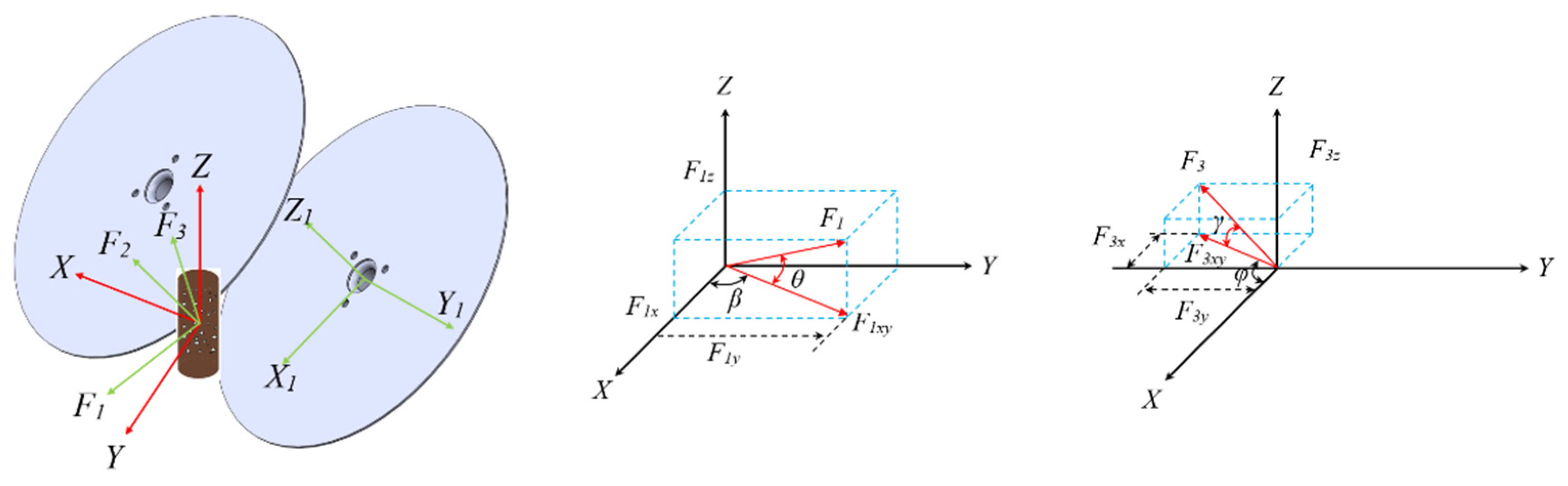
As shown in
Figure 15, the power of the root-cutting device comes from two servo motors. In the process of root cutting, the roots of cabbage are subjected to cutting forces
F1,
F2, and
F3 in the
X,
Y, and
Z-directions;
F1xy and
F3xy are the projection components of
F1 and
F3 in the
XY plane, respectively; and
F1x and
F1y are the projection components of
F1xy in the
X-axis and
Y-axis, respectively.
F3x and
F3y are the projection components of
F3xy in the
X-axis and
Y-axis, respectively.
β and
φ are the angles between
F1xy and
F3xy and the
X-direction, respectively. Because the cutting positions of the left and right cutters are asymmetric, and the two cutters overlap in the axial direction, there is still some cutting force in the
X-axis and
Z-axis directions (
F2). Under the combined action of the forces
F1z and
F3z in the
Z-axis direction and the feeding direction and the cutting friction force of the cabbage, the longitudinal component force above the cabbage is larger after receiving, which is helpful to clamp the rhizome of the cabbage [
25]. Due to the actual root-cutting process, the vertical plane angle
γ, which is the angle between the resultant force
F3xy and the force
F3 in the
XY plane, is small; therefore,
F1x can be approximated as the root main cutting force. In addition, considering the actual installation and use,
γ is set to zero, and only the influence of pitch angle
θ (the angle between the resultant force
F1xy and the force
F1 in the
XY plane) is considered in order to determine the best cutting parameters.
As shown in
Figure 16, it is assumed that the two disc cutters of the root cutting device are ideal discs, the cabbage is idealized as a round, and the diameter of the rhizome is
D1.
From the force analysis in the diagram, the following equations can be obtained:
where
RX is the root cutting force and
TY is the clamping force of the cutter on the rhizome.
N is the normal reaction force of the disc cutter on rhizomes; its horizontal component is
NX and its vertical component is
NY, N;
F is the friction of the circular cutter disc on the friction force of the circular cutter on the root of cabbage; its horizontal component is
FX and its vertical component is
FY, N.
In order to make the rhizome be held by the disc cutter, the following conditions must be met [
26]:
It can be deduced that:
FY >
NY, where
F =
N ·
f, that is:
Therefore, when
f >
tanα, the disc cutter has better clamping performance:
where
f is the friction coefficient between the disc cutter and the rhizome of cabbage;
α is the angle between the reaction force of the disc cutter on the cabbage rhizome and the
x-axis, (°);
L is the distance between two disc cutters, mm;
D1 is the root diameter of the cutting point, mm; and
D2 is the diameter of the disc cutter, mm.
The center distance of the designed double disc cutter is 190 mm, the diameter of the disc cutter is 200 mm, the angle α = 31.02°, and the overlap thickness of the two cutters is 5 mm. At this time, f > tanα, which can meet the requirements of clamping performance.
4.5. Design of Data Acquisition System
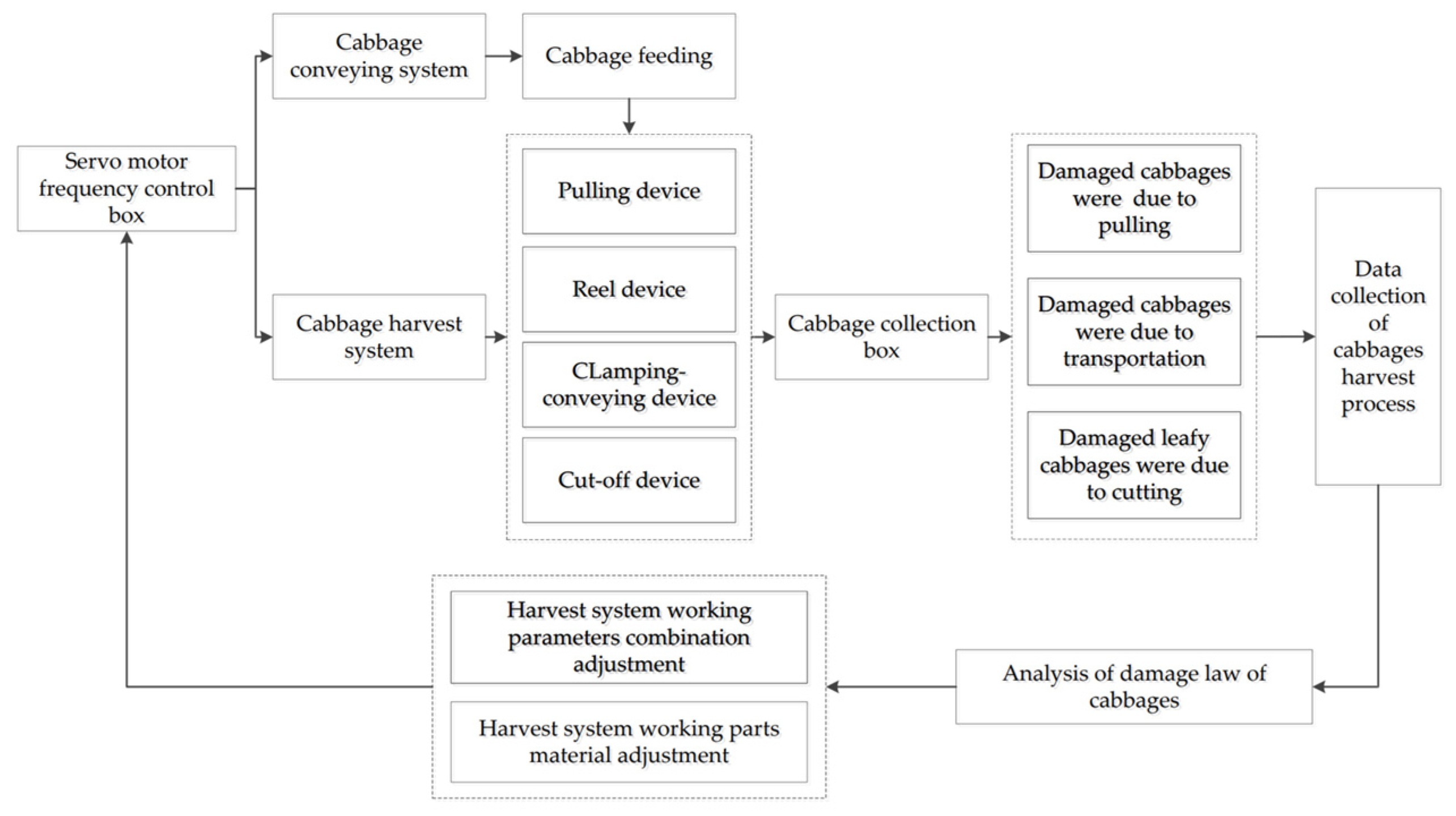
By installing torque and pressure sensors on the test platform to collect the speed and displacement of the cabbage in the harvesting system, the motion trajectory and speed–time curve of a single plant during the harvesting process are calibrated and tracked, and the damage to the cabbage after the harvesting operation is recorded and saved in order to find out the results of the movement of the cabbage in the pulling, conveying, and cutting of roots and determine the range of working parameters between different harvesting components.
The system uses the industrial tablet computer to install the INTOUCH HMI configuration software as the human–machine interface, which can ensure that the test bench starts operation according to the set test parameters. The monitoring acquisition system collects the operating data of each moving part, including torque, tension, speed, acceleration, and other data. The data acquisition cycle can be set, and the data chart curve can be automatically generated according to the recorded data.
The instrument panel graphics and text data list can display the following collected data: Left feeding inlet tension, right feeding inlet tension, conveying torque, left cutter torque, right cutter torque, left clamping conveying tension, right clamping conveying tension. Tension pressure data accuracy static: 1‰, tension pressure data dynamic static: 2‰, torque dynamic accuracy 2‰, each data can set the alarm value; if the data exceed the normal range, the system records and sends an alarm prompt. See
Figure 17.
According to the data obtained from the data acquisition system and the collection of cabbage in the aggregate box, the structural parameters and working parameters of each harvesting device in the harvesting system are adjusted in real time to reduce the damage rate of cabbage.


