Article

Design and Experiments of a Double-Cutterbar Combine Header Used in Wheat Combine Harvesters

College of Mechanical and Electrical Engineering, Henan Agricultural University, Zhengzhou 450002, China
*
Author to whom correspondence should be addressed.
Agriculture 2023, 13(4), 817; https://doi.org/10.3390/agriculture13040817
Submission received: 8 March 2023 / Revised: 30 March 2023 / Accepted: 30 March 2023 / Published: 31 March 2023
(This article belongs to the Special Issue Engineering Innovations in Agriculture)

Abstract

:
To solve the problems of congestion and increased power consumption of wheat combine harvesters (WCHs) caused by excessive feed rate, this paper proposes a method to reduce the feed rate by decreasing the feed length of the stalk and designs a double-cutterbar combine header (DCH). Using the threshing test bench and taking the feed rate, the feed length of the stalk, and the speed of the tangential threshing rotor as the influencing factors and the conveying time as the index, the influence of different parameters on the conveying performance was analyzed. The optimal parameters were obtained: the feed rate was 8 kg/s, the feed length of the stalk was 380 mm, the speed of the cutting drum was 554 r/min, and the conveying time was 8.089 s. The optimized parameter combination was tested and verified, and the test results show that the relative error with the predicted value was 0.198%, proving the reliability of the optimized parameters. The critical components of the DCH were designed, the movement process of the profiling mechanism was simulated using ADAMS software, and the structural dimensions of the profiling mechanism were determined. The field performance test of the WCH with a DCH was carried out. The results showed that the loss rate and stubble height met the operation quality requirements. At the same operation speed, the fuel consumption was 11.2% less than that of the WCH with a conventional header, providing a technical reference for the efficient harvest of the WCHs.

1. Introduction

When harvesting, the feed rate of WCHs constantly changes due to factors including header height, harvesting speed, crop moisture content, and density [1,2,3,4]. Farmers have recently used plant growth regulators in the wheat plantation process to improve wheat yield, which leads to the high moisture content of wheat stalks during harvest. Compared with the low moisture content of wheat stalks, the feed rate of the WCHs will increase at the same harvest speed, which further increases the workload imposed on the operating parts of the WCHs and even causes blockages. Methods such as elevating the header or reducing the cutting width and operating speed of WCHs are usually adopted to adjust the feed rate to avoid blockages. However, elevating the header will increase the stubble height, which affects the operation quality and is not conducive to subsequent crop planting [5]. At the same time, reducing the cutting width and operating speed will reduce the operational efficiency and increase the harvest loss [6].
As an essential part of the WCH, the header significantly impacts the harvest quality [7]. Most WCHs in China use rigid screw conveyor headers and a mechanical transmission system. Large-scale WCHs in other countries mostly use flexible transmission belt headers with high intelligence. Many scholars have also researched the automatic control of header operation parameters in recent years. Through automatic adjustment of header height [8,9,10,11,12,13,14], reel height and rotation speed [15,16,17], and screw conveyor clearance [18], problems such as combined harvester congestion and increased harvest loss caused by changes in feed rate can be mitigated. Still, it is only partially suitable for China’s wheat harvest operation. In their research on the structure of the combine header, Li et al. [19] optimized the structure parameters of the header frame. Xie et al. [20] designed a belt conveyor header for the soybean combine harvester to solve the problems of uneven feeding and congestion. Zhang et al. [21] designed a double crank plane five-bar reel mechanism to solve issues such as easy winding and hanging straws of the reel. Qing et al. [7] designed a reel with improved tine trajectory for harvesting oilseed rape to reduce harvest loss. Van et al. [22] designed a screw conveyor based on a cam mechanism for retracting the fingers to solve the problem of a dead zone between the screw conveyor and inclined conveyor and to improve conveying performance.
The factor limiting the performance of the combine harvester is its ability to handle a large amount of stalk and separate the grain from it. To reduce the number of stalks entering the combine harvester, Shelbourne Company designed the stripper header, which only combs the grains off the stalks and feeds them into the combine harvester, which can effectively reduce the feed rate but results in a high harvest loss [23,24]. Wang [25] once proposed to feed only the head of grain into the combine harvester and designed a secondary cutting and directional conveying device. The test results show that reducing the feed length can effectively reduce power consumption and improve operation efficiency, but its adaptability could be better. Dai et al. [26] designed a plot wheat seed harvester, which realized the harvest of wheat spike and effectively reduced the load of the threshing and cleaning system. The above research shows that harvesting only the upper part of the wheat plant is feasible. This paper proposes a method to reduce the feed rate by reducing the feed length of the wheat stalk and determines the optimal feed length of the wheat stalk through bench tests. The DCH of the WCH is designed to solve the problems of congestion and increased power consumption.

2. Materials and Methods

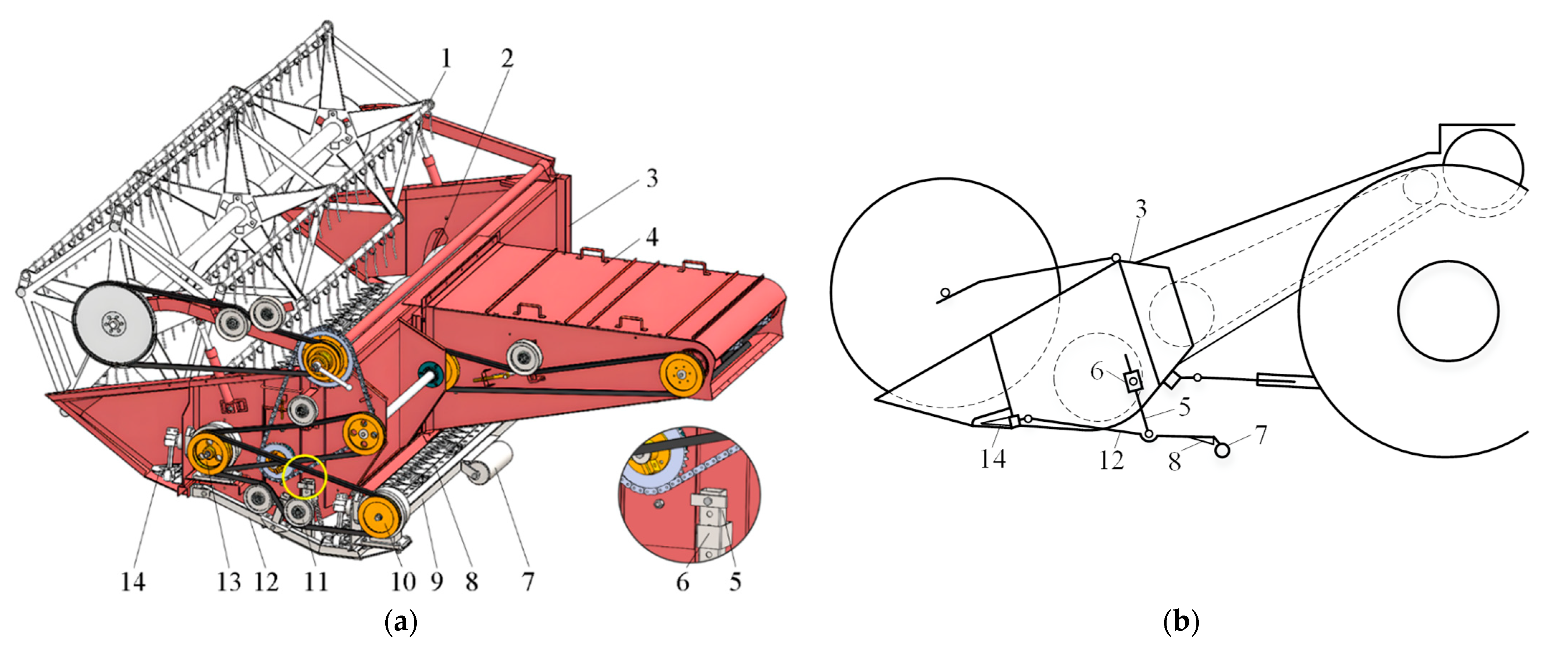
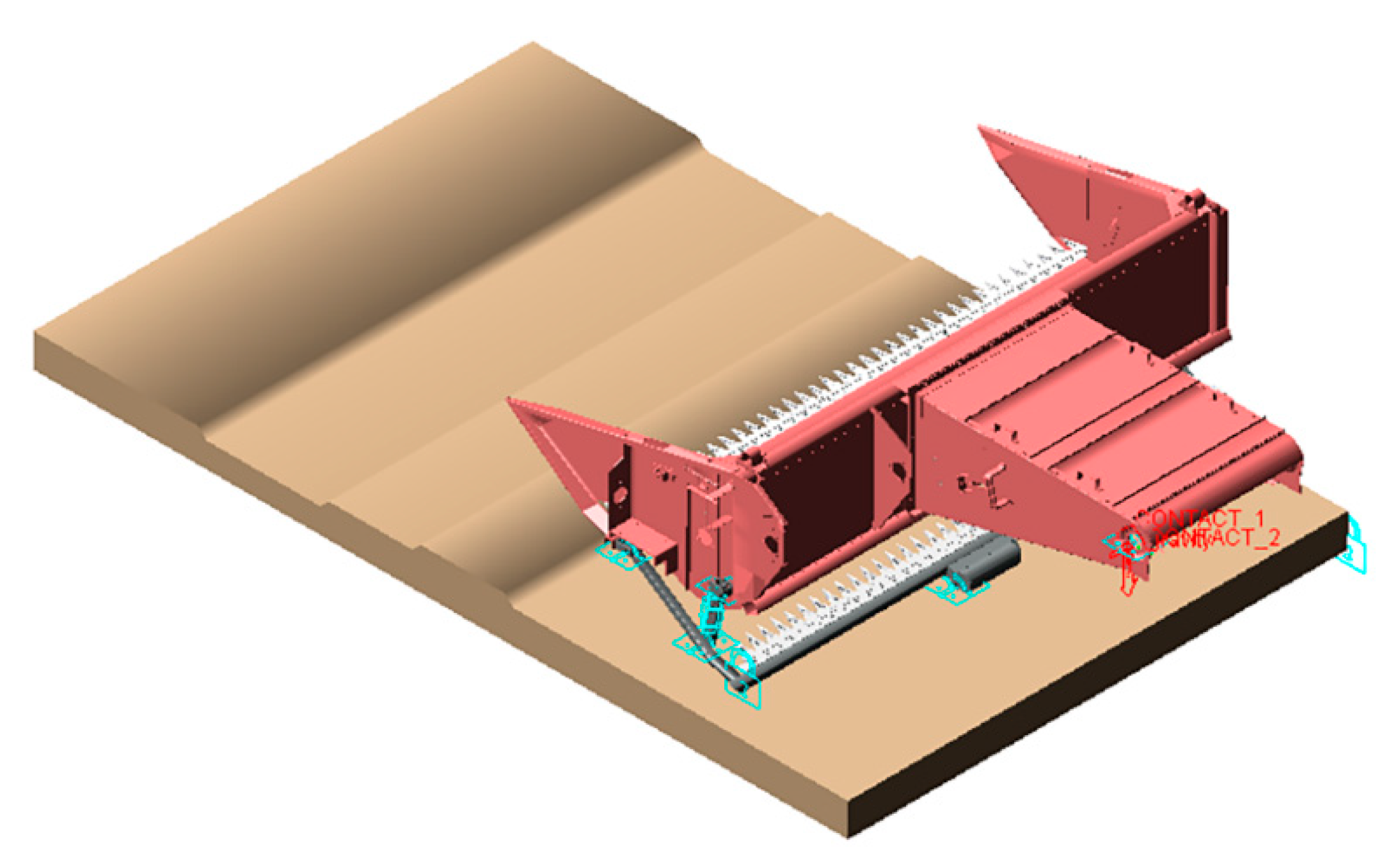
2.1. Structure and Working Principles of the DCH

A DCH was designed based on the horizontal screw conveyor header of WCHs, which has two layers of cutterbars, as shown in Figure 1a. The DCH is mainly composed of the frame, a reel, a screw conveyor, upper cutterbars, lower cutterbars, wobble boxes, a profiling mechanism, and a transmission system. Among them, the profiling mechanism consists of a fixed beam, support arms, a height-limiting connecting rod, a swing block, and the ground wheel of the upper cutter. The swing block, support arm, and connecting rod installed with a height-limiting block form a crank rocker mechanism, as shown in Figure 1b. The fixed beam is welded to the support arms on both sides, and the upper cutter and ground wheel are installed on the fixed beam. In the case of uneven terrain, the profiling mechanism can enable the lower cutterbars to fluctuate with the change in wheat field terrain, which ensures consistency of cutting height and protects the cutterbars from damage to some extent.
Before an operation, a hydraulic height adjustment handle on the DCH is used to lower the header. In lowering the header, the ground wheel is the first to come into contact with the ground. The height of the lower cutterbars no longer undergoes significant fluctuation, while the upper cutterbars continue to descend to the set height. A schematic representation of the DCH in service is shown in Figure 2. The plant height of wheat is L1; the upper cutterbars first cut the upper part of the wheat stalks, which can then be pulled into the screw conveyor under the effect of the reel. The cut part with a stalk length of L2 is fed into the combine harvester; the middle part of the wheat stalks can be cut by the lower cutterbars and then scattered across the field. The length of the central part of wheat stalks is L3. The uncut part of the wheat stalks remains on the ground, forming stubble with a height of h. The fixed scale of the oil cylinder on the DCH can be adjusted to tune the length of stalks cut by the upper cutterbars to adapt to harvesting wheat plants with different heights.

2.2. Conveying Performance Bench Test

When using the DCHs to harvest wheat, the length of the wheat stalk cut by the header and fed into the combine does not match the working parameters of the relevant DCH parts, which adversely affects the conveying performance. Therefore, to reduce the probability of congestion, a test was carried out on the threshing test bench to determine the best stalk feed length and working parameters by exploring the influence of the parameters of WCHs on the conveying performance, which can provide the basis for the structural design of the DCH.

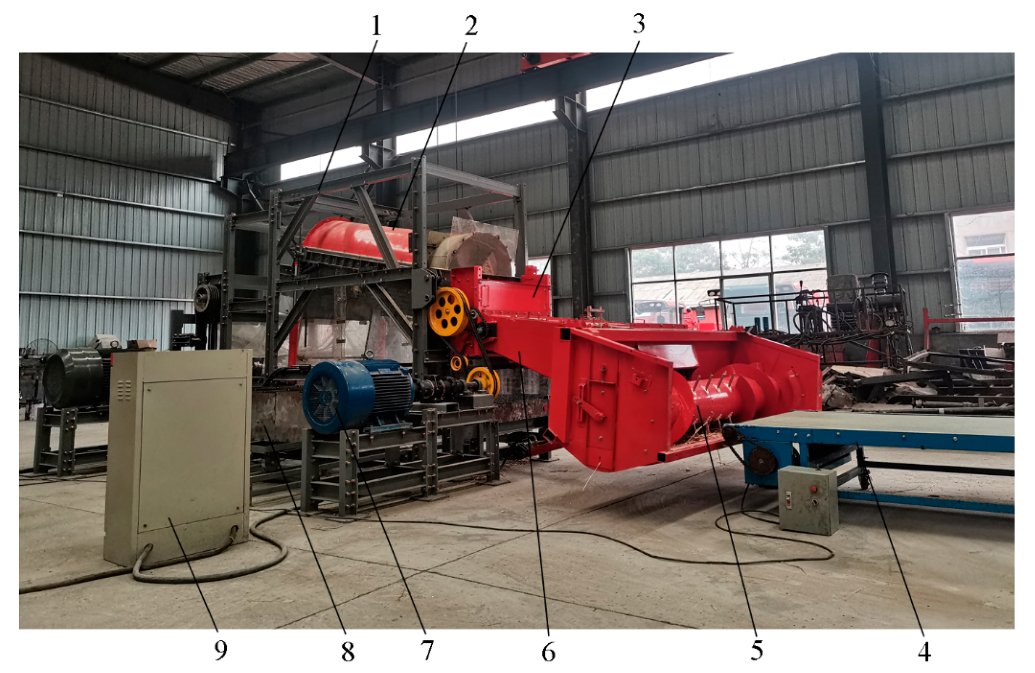
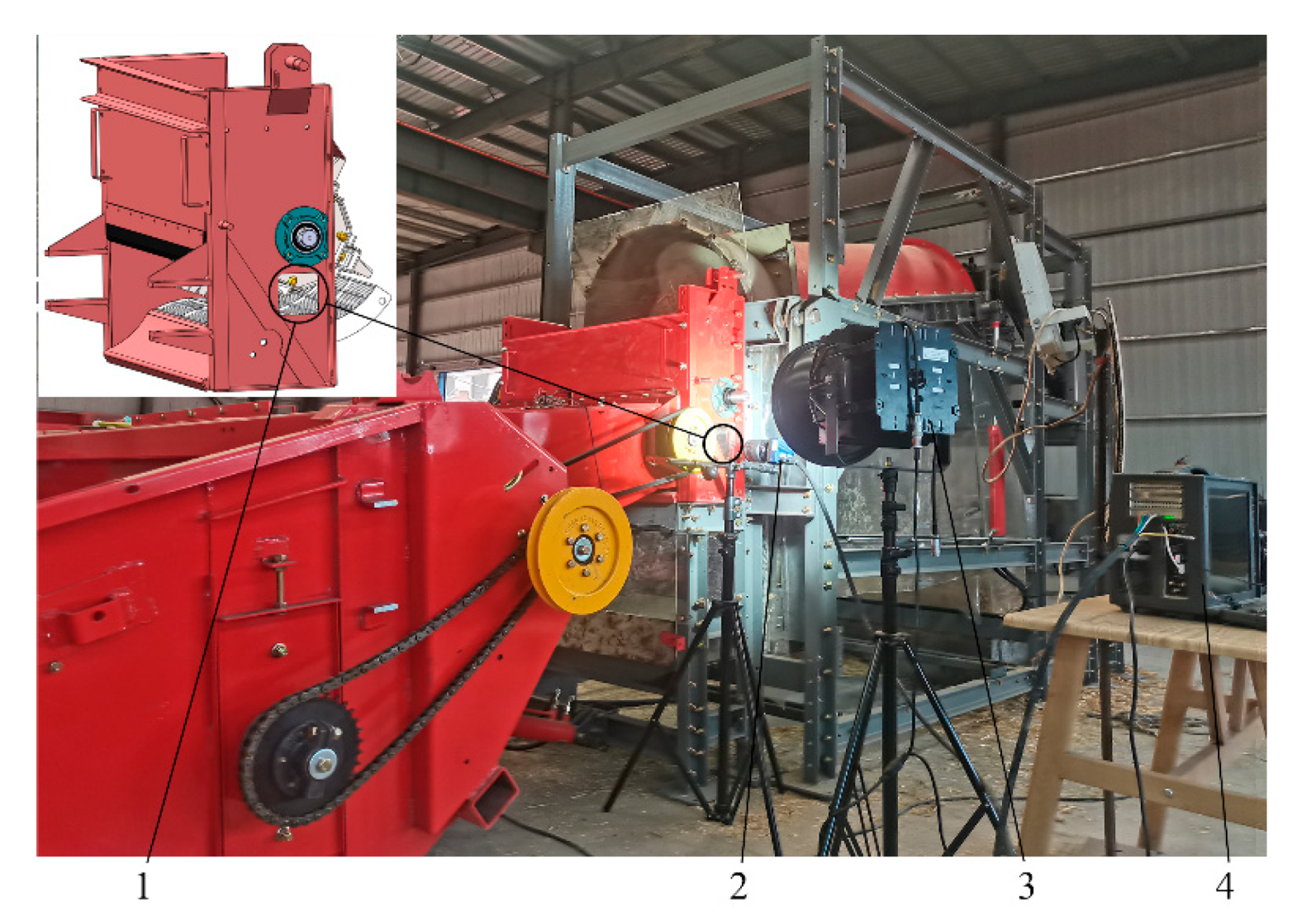
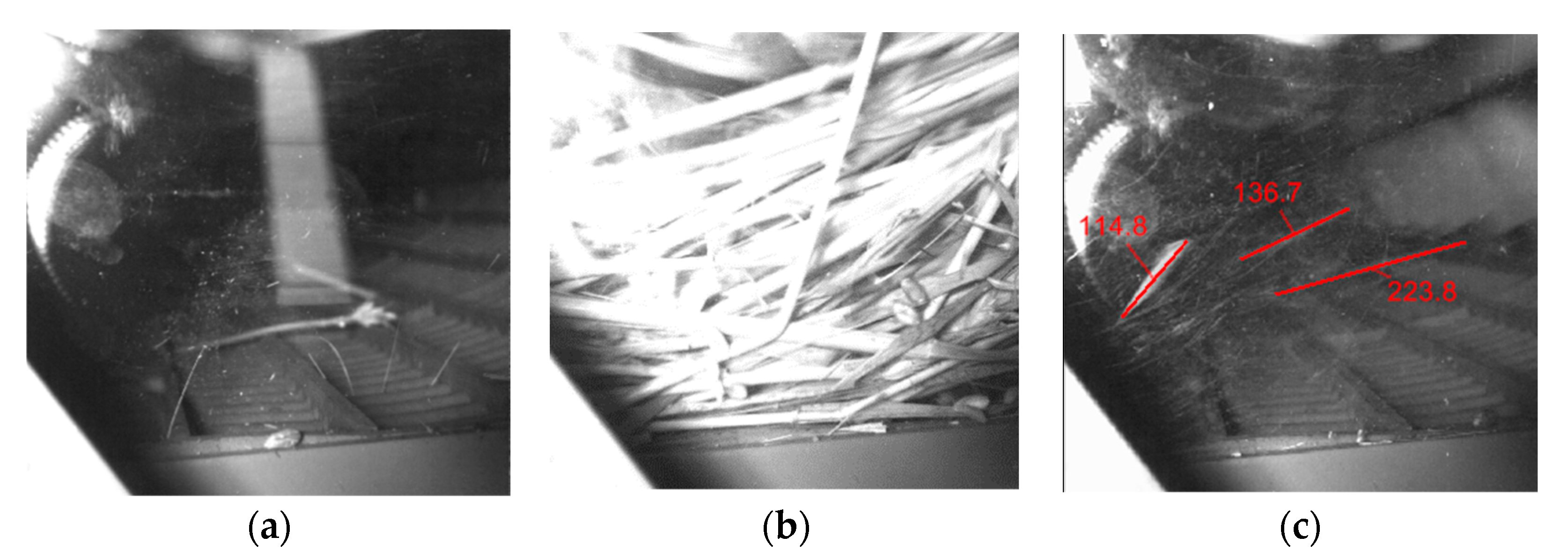
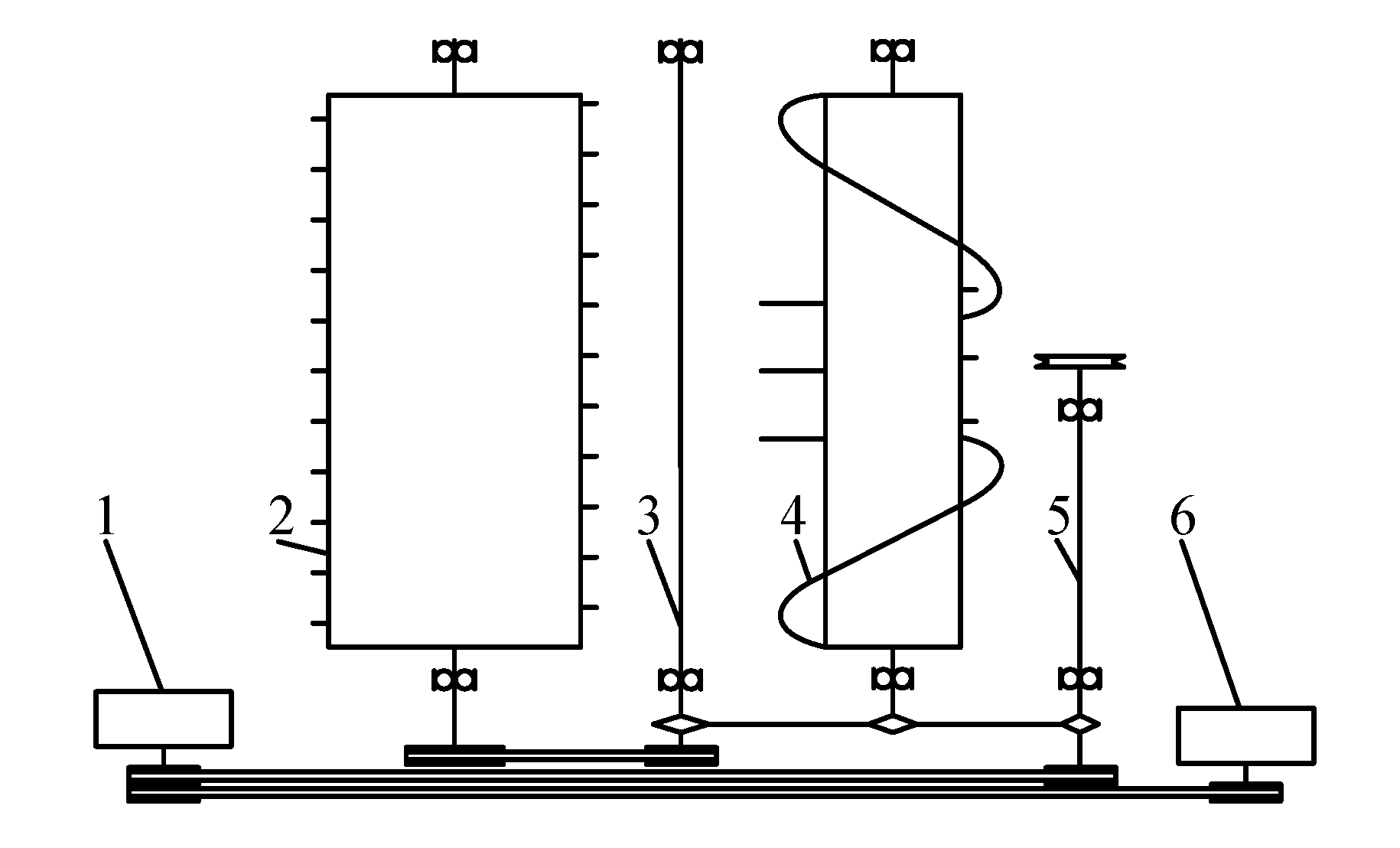
2.2.1. Test Equipment

The structure of the threshing test bench consists of a frame, a longitudinal axial flow threshing and separating device, a tangential flow threshing and separating device, an inclined conveyor, a screw conveyor, a material conveying platform, and a grain collecting box, as shown in Figure 3. The tangential flow threshing and separating device, inclined conveyor, and screw conveyor bring wheat stalks into the longitudinal axial flow threshing and separating device. In contrast, the tangential flow threshing and separating device completes some of the threshing tasks. Moreover, a 37 kW three-phase asynchronous motor and its supporting frequency converter are used simultaneously to drive the tangential flow threshing rotor, the inclined conveyor, and the screw conveyor and adjust their speeds. The longitudinal axial flow threshing rotor imposes a significant workload; a 75 kW three-phase asynchronous motor and its supporting frequency converter are exclusively used for driving the threshing rotor, for which the angular velocity is also adjusted. The material conveying platform is 10 m long and feeds wheat stalks into the harvester. The frequency converter is used to adjust the rotational speed of the asynchronous motor to change the conveying velocity, thereby controlling the feed rate.

2.2.2. Experimental Materials and Methods

The test wheat cultivar was Zhoumai 32, and its average plant height was 743 mm. The test used manually harvested wheat and a cutting height of 50 to 80 mm. The grain moisture content was identified as 14.2%.
Combining this with the requirements of Equipment for harvesting—Combine harvesters—Test Procedure (GB /T 8097-2008), conveying time was taken as the testing indicator for the performance of conveying. The conveying time refers to when the wheat is first conveyed by the conveying platform to the screw conveyor, then passes through the inclined conveyor and the tangential flow threshing rotor, and finally arrives at the longitudinal axial flow threshing rotor. An observation window is set on the side sealing plate of the tangential threshing device, and the NORPIX FR-1000 high-speed digital camera is used to photograph the movement of materials in the transition area of the tangential axial threshing device, as shown in Figure 4. In the test, the acquisition frame rate of the high-speed digital camera was set to 200 frames per second, and the image recording began when turning on the conveying platform. The time taken for the material conveying platform to deliver the wheat to the screw conveyor is t1. After the tests ended, Image-Pro Premier image analysis software was used to analyze the collected images. To avoid a small number of stalks remaining in the header frame and inclined conveyor during the later stage of material conveying from affecting the judgment of the end time, based on less than or equal to five stalks in five consecutive frames of images, the time corresponding to the first frame of the image was selected as the end time t2 [27], as shown in Figure 5. The results of the experiments have shown that the number of images with less than or equal to five stalks in succession is less than 10 frames, so the error in judging the conveying time of high-speed photographic images is less than 0.05 s. The conveying time t is:
t = t 2 t 1
Three factors and three levels of the Box–Behnken response surface analysis methods were used in the test [28]. The test factors, such as feed rate, feed length of stalk, and speed of the tangential threshing rotor, were expressed as A, B, and C, respectively, and the conveying time was the test indicator, which was expressed as Y. The coding table of test factors is shown in Table 1.
Adjust the speed of the axial threshing rotor to 900 r/min and the speed of the conveying bench to 1 m/s. Cut the harvested wheat stalks and keep the upper part of the stalks at 300 mm, 450 mm, and 600 mm, respectively. Weigh the materials with different lengths of 24 kg, 27 kg, and 30 kg by an electronic scale and lay them evenly on the rear 3 m conveying platform with the wheat ears toward the threshing test bench to achieve feeding speeds of 8 kg/s, 9 kg/s, and 10 kg/s.

2.3. Design of Critical Components of the DCH
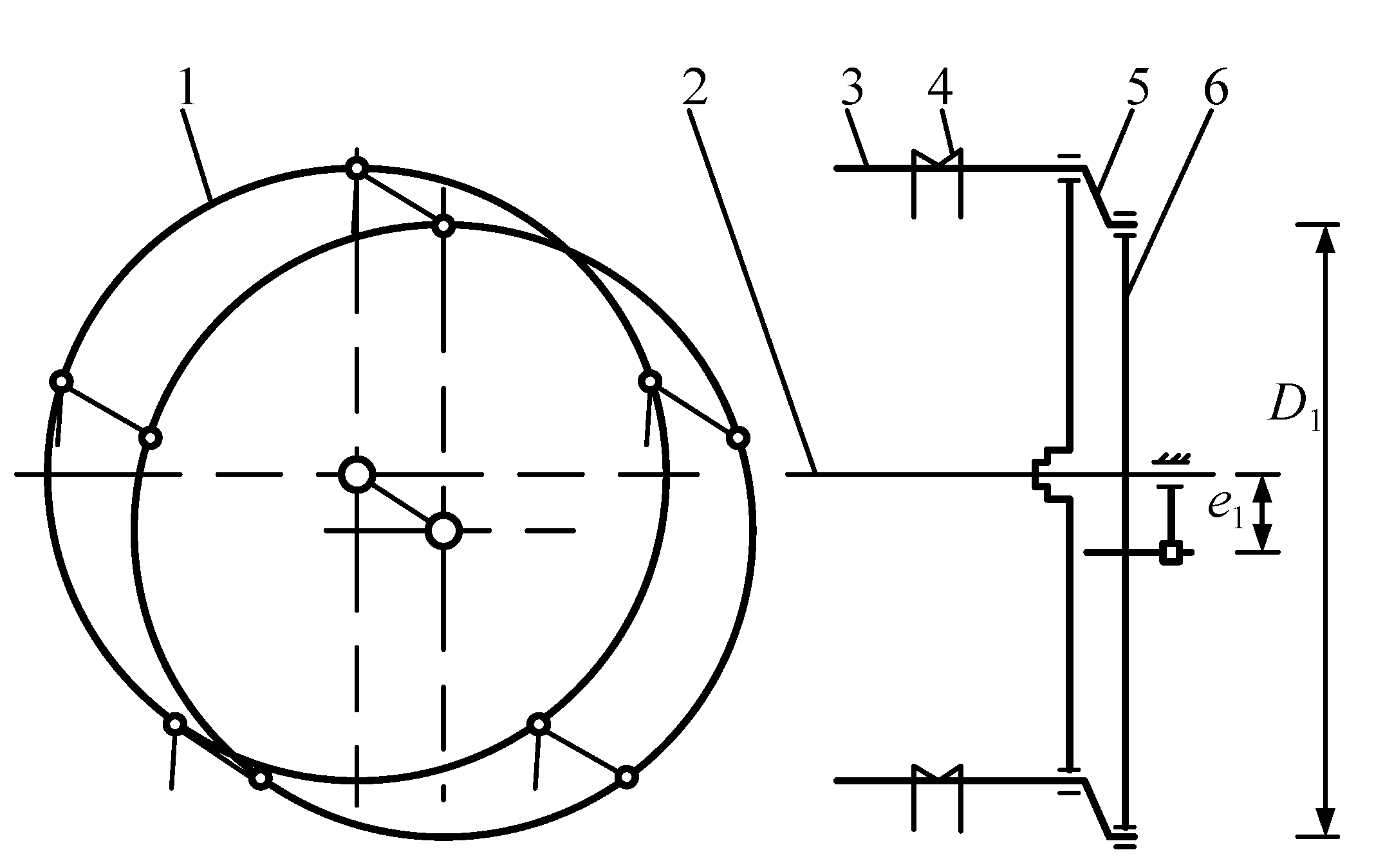
2.3.1. Reel

A reel is installed at the front of the DCH, which picks up and conveys wheat stalks into the cutting device. In this process, the reel also supports the wheat stalks being cut. The reel can help the cutting device fulfill the cutting operation while pushing harvested wheat stalks into the screw conveyor to avoid cut stalks piling up at the front of the header. As a cam-action reel exerts a strong stalk-lifting force and has a small impact on cropped ear-heads, they are primarily used in rice and WCHs. The structure consists of central spoke wheels, a central rotatable shaft, tine bars, tines, an eccentric spoke wheel, and cranks, as shown in Figure 6. The eccentric spoke wheel, cranks, and central spoke wheel constitute a parallel four-bar linkage mechanism that allows the tines to maintain a well-adjusted dip angle. The diameter of the reel D1 is 1000 mm, and the eccentricity of an eccentric spoke wheel and central spoke wheel e1 is 72 mm.

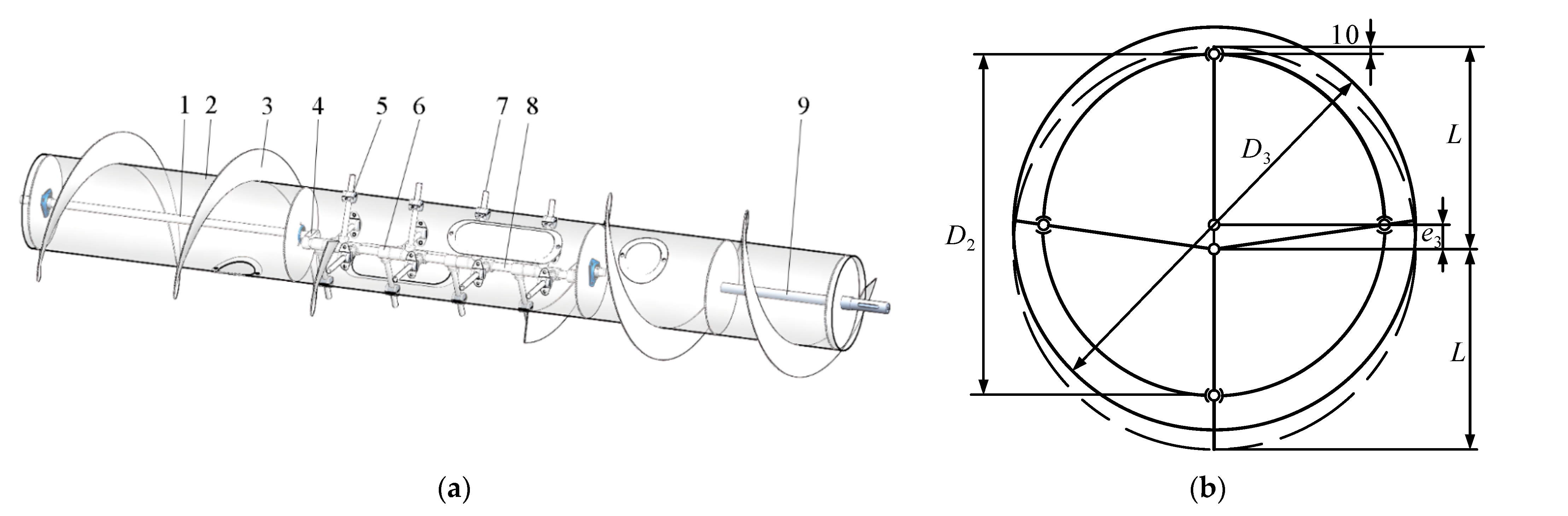
2.3.2. Screw Conveyor

The structure of the screw conveyor is composed of a cylinder welded with left- and right-handed spiral blades and retractable fingers (Figure 7). The retractable fingers are installed at the screw cylinder, and 16 retractable fingers (with four retractable fingers in each group) are hinged abreast on the retractable finger shaft. The retractable fingers are riveted to a crank and a fixed shaft. The eccentric distance between the center of the retractable fingers and the screw cylinder is e2. To avoid the winding of wheat stalks, the perimeter of the screw cylinder must be larger than the length of wheat stalks that have entered the DCH [29]. Generally, the diameter D2 of the screw cylinder is 300 mm. To improve the conveying performance of the spiral conveyor on short wheat stalks, the outer diameter of the spiral blades D3 is 500 mm, and the screw pitch S is 460 mm.
The screw cylinder, when rotating, drives the retractable fingers to also rotate. As the screw cylinder and retractable fingers are not concentric, the retractable fingers undergo telescopic motion relative to the screw cylinder surface. When the retractable fingers turn back, they should retract into the screw cylinder, but their protrusion of 10 mm remaining outside the screw cylinder should be ensured to avoid the wear-out of the ends of the retractable fingers. When the retractable fingers turn forward, they should stretch to 40–50 mm outside the spiral blades within the screw cylinder in a bid to ensure their clamping capability [30]. Thus, we obtain,
e 2 = D 3 D 2 4 + ( 15 ~ 20 )
L = D 2 2 + 10 + e 2
where e2 is set to 70 mm and the length of retractable fingers L is 280 mm.

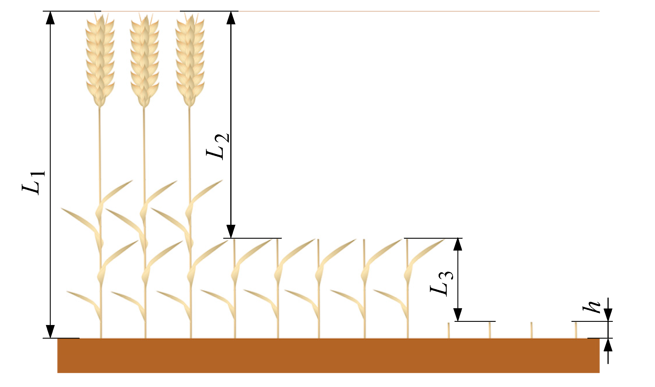
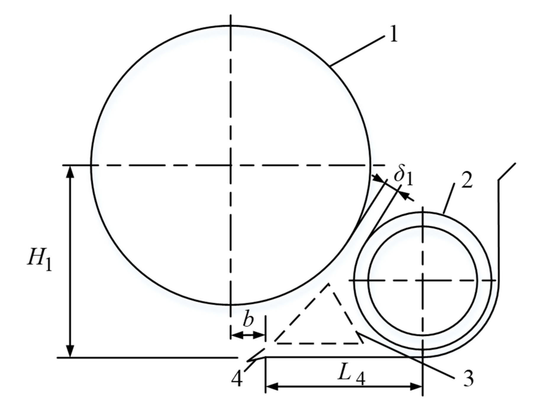
2.3.3. Parameters of the Header Triangle

The triangle of the header refers to a particular space composed of three main working parts: a reel, a cutterbar, and a screw conveyor, as shown in Figure 8. Compared with the conventional header, the wheat stalks cut and transported by the DCH are short in length. The triangle is too large, so the crops quickly accumulate between the cutter and the screw conveyor. When the crop is stacked to a certain amount, it will be grabbed by the blades of the screw conveyor, resulting in uneven transportation, feeding, and even blocking; if the triangle area is too small, the harvest loss will increase. The vertical distance H1 between the central rotatable shaft of the reel and the upper cutterbar, the horizontal distance L4 between the screw conveyor center and the upper cutterbar beam, and the forward displacement b of the central rotatable shaft (taking the central rotatable shaft directly above the upper cutterbar as the central position) affect the size of the triangle. L4 is usually 350–500 mm. We selected L4 as 450 mm. To make the reel tine shaft have a backward horizontal speed above the cutter, the maximum forward displacement of the reel main shaft bmax is [30]:
b max = D 1 2 λ λ 2 1
In Formula (4), λ is the ratio of the circumferential speed of the reel to the operating speed of the combine harvester, which is generally 1.5–1.7 [30]. Taking λ as 1.5, the bmax is 298 mm. The reel can move back correctly to increase its ability to push the stalk, but the distance from the screw conveyor when the reel is adjusted to the final position δ1 should be greater than 25 mm.
Combined with the best straw feed length determined by the bench test, the minimum height of H1 is 753 mm, calculated according to Formula (5) [30].
H 1 D 1 2 + 2 L 1 L 3 h 3 = D 1 2 + 2 L 2 3

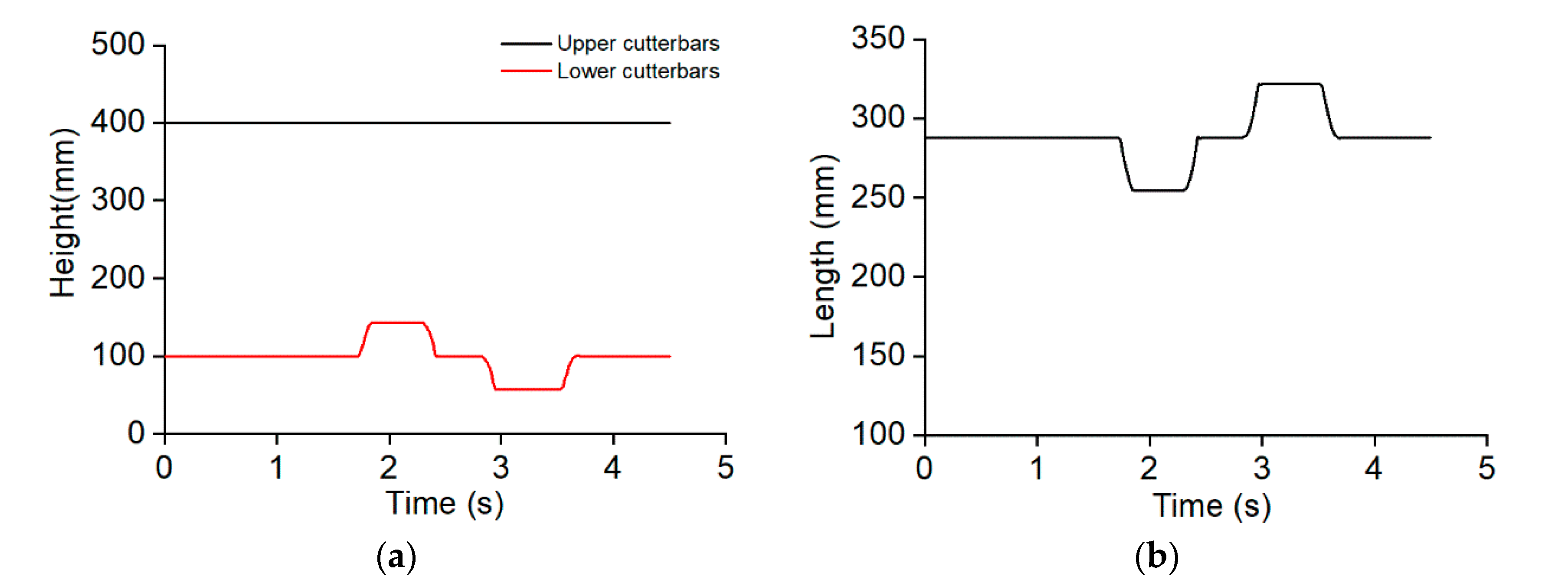
2.3.4. Profiling Mechanism of the Lower Cutterbar

As shown in Figure 1, the support arm, height-limiting connecting rod, swing block, and ground wheels of the profiling mechanism for the lower cutterbar constitute the swing block of the crank. When harvesting, the greater the distance between the upper cutterbar and the ground of the wheat field, the larger the length of the height-limiting connecting rod. However, due to the influences of the DCH’s structure and transmission system, the height-limiting connecting rod should be a suitable length.
Statistics indicate that the average plant height of the main wheat varieties in Henan Province, China, is 775 mm. The maximum distance between the ground and upper cutterbar is preliminarily determined to be 400 mm to meet the optimum feed length of stalks. Meanwhile, the lower cutterbar can fluctuate by up to 50 mm with the ground height. The LBA was determined using ADAMS software to simulate and study two processes: (1) the motions of the components with the DCH descending and (2) their motions with a change in ground height during harvest. Create a ground with 50 mm bumps and depressions using 3D software, assemble it with a simplified model of the DCH according to actual working conditions, import the model into ADAMS software, merge the upper cutterbars, header frame, and inclined conveyor frame, merge the lower cutterbars and fixed beam, and add motion constraints to the moving parts. During the simulation of header descent, the motion constraints are shown in Table 2. Establish a height sensor between the upper cutterbars and the ground to stop the header from descending after the upper cutterbars reach the set height. The simulation model is shown in Figure 9. During the harvesting simulation, adjust the model to make the ground wheel contact the ground; change constraint 1 in Table 2 to a translational joint; and add a driver to achieve the DCH movement.

2.3.5. Transmission System

The transmission system of DCH is shown in Figure 10. The power of the engine is transmitted to the DCH through the belt and chain drive. Then the driving shaft of the DCH can transfer power through the belt drive transmission to the wobble box of the upper cutterbars. The wobble boxes of the upper and lower cutterbars can transfer power through the belt drive transmission to power both the upper and lower movable cutters. Meanwhile, the driving shaft of the DCH drives the rotation of the screw conveyor by way of a chain drive transmission. The transmission occurs between the driving shaft and the reel to drive the rotation of the reel through the chain and belt drive transmission. The transmission ratio is shown in Table 3.

2.4. Field Experiment

2.4.1. Experimental Arrangement

On 30 May 2022, Xinjiang-9B type WCHs equipped with the newly designed DCH and conventional header were subjected to in-situ operating tests in Xingyang, Henan Province, China. Field surveys were made according to the requirements of relevant standards. The wheat cultivar was Zhoumai 32, with an average plant height of 743 mm and a grain moisture content of 14.5%. The ratio of stalk to grain was 1.18, and testing conditions met the requirements [31]. The suitable field plot should satisfy the criteria, including that the measured zone should be 50 m long, there must be a stable zone 20 m in front of the measured zone, and a harvester parking site no less than 15 m behind the measured zone; the stubble height is 100 to 120 mm [32]. In the experiment, the combine harvesters worked along the lengthwise direction of field plots at a speed of 5 km/h.

2.4.2. Data Collection and Processing

A 1 m2 sampling zone was selected in the representative zone along the advancing direction of the combine harvesters at each sampling site. In the sampling zones, all grains and ear-heads were collected; thereafter, once threshed and cleaned, they were weighed. Based on Equations (6) and (7), the harvesting loss rates were calculated, respectively, and then the average value of the harvest loss rates in the five sampling zones was determined [33].
F j = W s h W z W c h × 100
F = F j 5
where Fj is the loss rate of the sampling point, %; Wsh is the mass of grain loss per square meter, g/m2; Wz is the mass of grains naturally falling per square meter, g/m2; Wch is the mass of grain per square meter, g/m2; and F is the average harvest loss rate, %.
The stubble height was measured using the five-point sampling method applied in the experimental field. The stubble heights of three subpoints were determined by measuring at the left, middle, and right sides of the horizontal direction of the harvesting range in each point. The average value of the three subpoints was taken as the stubble height at that point, taking the mean average value of the five points.
Before each experiment, the same amount of diesel oil was added to the fuel tank. After completing the test, the diesel oil remaining in the fuel tank was discharged and weighed. According to Equation (8), the fuel consumption per unit area Q could be calculated. Two groups of tests were repeated three times before taking the mean average value.
Q = 10000 × q 1 q 2 B × L 4
In the formula, q1 is the weight of fuel in the fuel tank before a test, kg; q2 is the weight of fuel in the fuel tank at the end of a test, kg; B is the cutting width of the WCH, m; and L4 is the length of the measured zone, m.

3. Results and Discussion

3.1. Conveying Performance Test Analysis

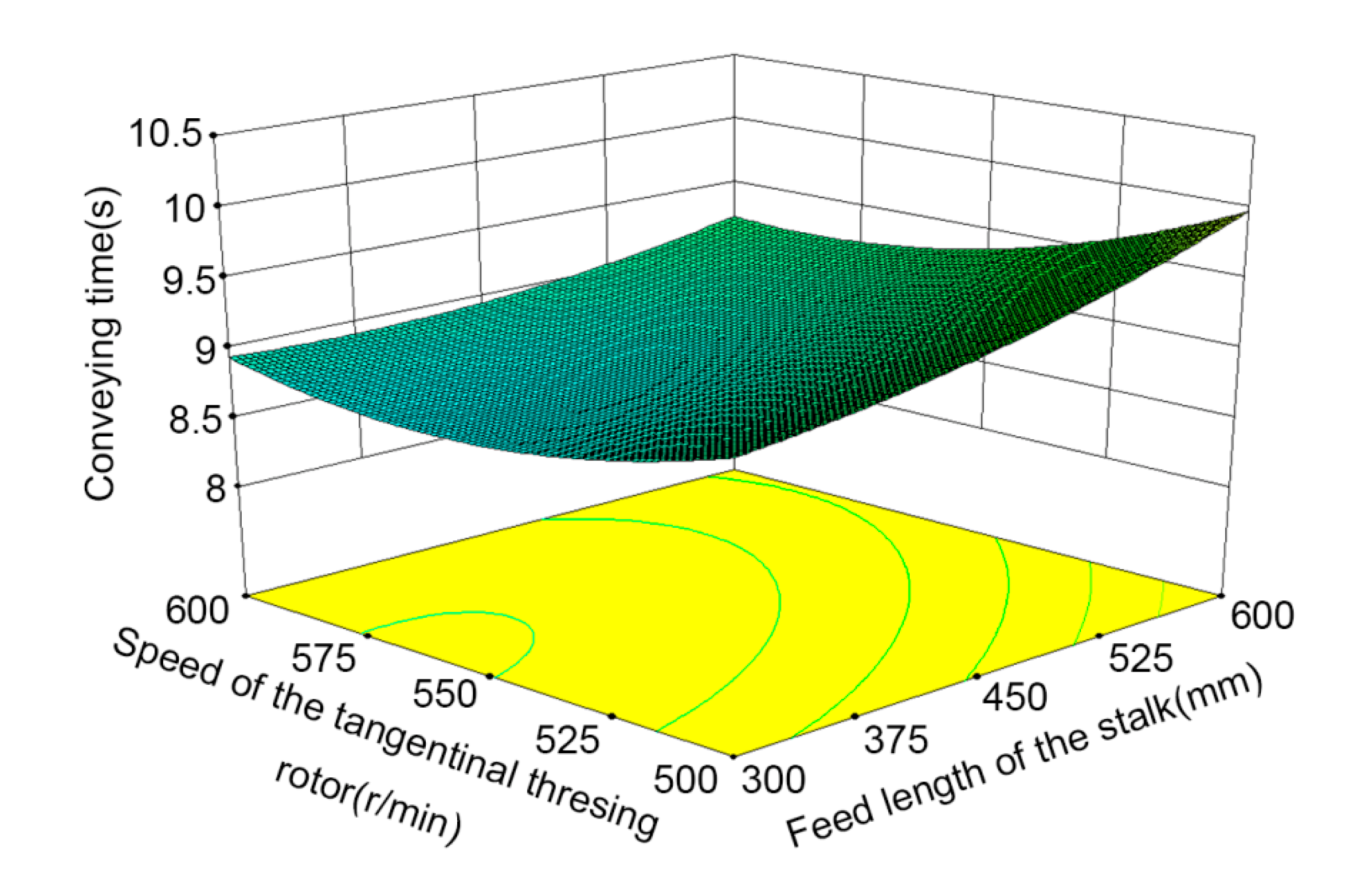
3.1.1. Regression Analysis

The experimental results are shown in Table 4. Using Design-Expert 8.0.6 software to regress and fit the experimental results, we obtained the regression mathematical model of conveying time Y:
Y = 0.212 A 2 + 5.463 × 10 6 B 2 + 1.057 × 10 4 C 2 + 6.25 × 10 4 A B 1.65 × 10 3 A C 1.75 × 10 5 B C 2 . 181 A + 9.5 × 10 4 B 0.0983 C + 41 . 932
The determination coefficient R2 of the regression equation was 0.998, indicating a high degree of fitting; the regression model was analyzed by variance, and the results are shown in Table 5. It can be observed that the model had a value of p< 0.0001, indicating that the regression equation is significant and can describe the relationship between each factor and response value; the lack of fit wasp = 0.1882 > 0.05, showing that the residual item is not significant, and there are no other main factors affecting the results, so the regression model was established. p < 0.01 was set for A, B, C, BC, A2,B2, and C2, which have a very significant effect on the results; p < 0.05 was set for AB and AC, indicating that they have a significant effect on the results; and p > 0.05 was set for factors and interaction terms, which have no significant effect on the results. The order of significance of each factor on the screening efficiency, from large to small, was feed rate, feed length of the stalk, and speed of the tangential threshing rotor.
According to the regression equation, the influence of the interaction of factors on the results is shown in Figure 11. When the speed of the tangential threshing rotor is low, the conveying time decreases with the shorter feed length of the stalk. The shorter the length of the stalk, the better the passing performance in the transition area between the tangential threshing rotor and the longitudinal axial flow rotor, and the shorter the conveying time. When the speed of the tangential threshing rotor is high, the conveying time decreases first and then increases with the shortening of the feed length of the stalk. The conveying time decreases first and then increases with the increasing speed of the tangential threshing. This is because the conveying capacity increases when the rotating speed of the cutting drum increases; if the speed of the tangential threshing rotor is too high, the stalks are not fed in time by the axial threshing rotor, and there is congestion in the transition between the axial flow rotor and the tangential threshing rotor, causing the conveying time to increase.

3.1.2. Parameter Optimization and Verification

In order to achieve better material-conveying performance, the optimization module was used to optimize the regression model and set the solution target as the minimum response value [34]. The optimal parameter combination was obtained as follows: feed rate 8.06 kg/s, feed length of the stalk 377.19 mm, speed of the tangential threshing rotor 553.84 r/min. The optimal parameter combination was rounded as follows: feed rate of 8 kg/s, feed length of the stalk 380 mm, speed of the tangential threshing rotor 554 r/min, and conveying time 8.089 s. The optimized parameter combination was tested and verified. The average value of the five tests was taken, the conveying time was 8.105 s, and the relative error with the predicted value was 0.198%, verifying the reliability of the optimized parameters.

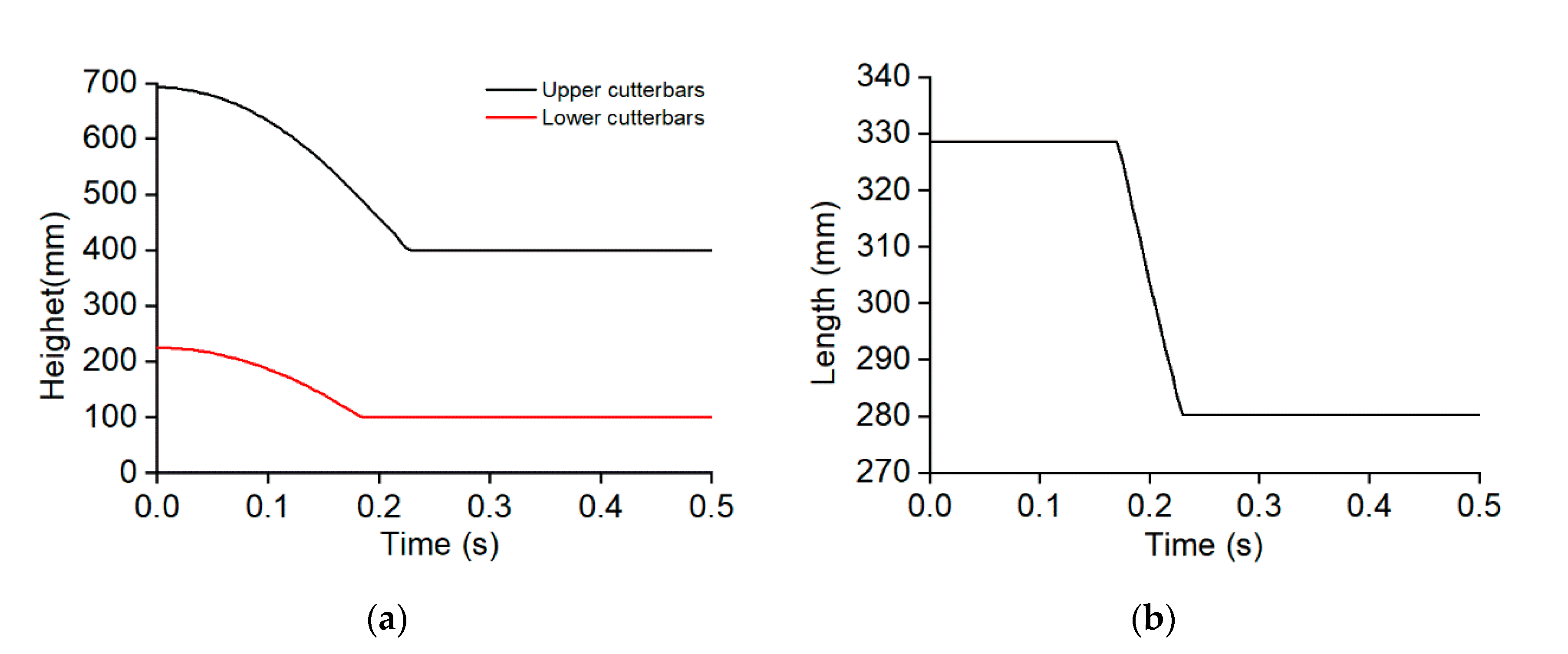
3.2. Simulation Analysis of the Profiling Mechanism of the Lower Cutterbar

The changes in the upper and lower cutterbars, as well as the varying LBA while the DCH descended, are displayed in Figure 12. At the beginning of the simulation, under the effect of gravity, the height-limiting block and the swing block make contact with each other; no relative sliding occurs between the height-limiting connecting rod and the swing block; and the lower and upper cutterbars descend simultaneously. The simulation time is 0.185 s. In the profiling mechanism, the ground wheel makes contact with the ground, the height of the lower cutterbars no longer shows a large range of change, and the header continues to descend. Meanwhile, due to the supporting effect of the ground surface on the ground wheel, the height-limiting connecting rod begins to move upwards along the swing block, and the height of the lower cutterbars slowly drops, accompanied by a decrease in LBA; the simulation ends when the height of the upper cutterbars reaches 400 mm. In this case, the upper and lower cutterbars no longer change positions. The height of the lower cutterbars is 100 mm, and LBA is decreased from 328.6 mm to 280.2 mm.
In the simulation of the motion of components with the change in ground heights during harvesting, the changes in upper cutterbars and lower cutterbars, as well as varying LBA, are displayed in Figure 13. The height of the upper cutterbars is kept unchanged, while the height of the lower cutterbars, when a hump is encountered on the ground wheel, increases and decreases in the case of a concave ground profile, finally realizing the function of the profiling mechanism. According to Figure 13b, in this process, LBA is shown to change within the range of 254.7 mm to 322.1 mm. By combining the change in LBA during the descent of the header with the dimensions of the swing block and height-limiting block, the length of the height-limiting connecting rod of the profiling mechanism is found to be 365 mm.

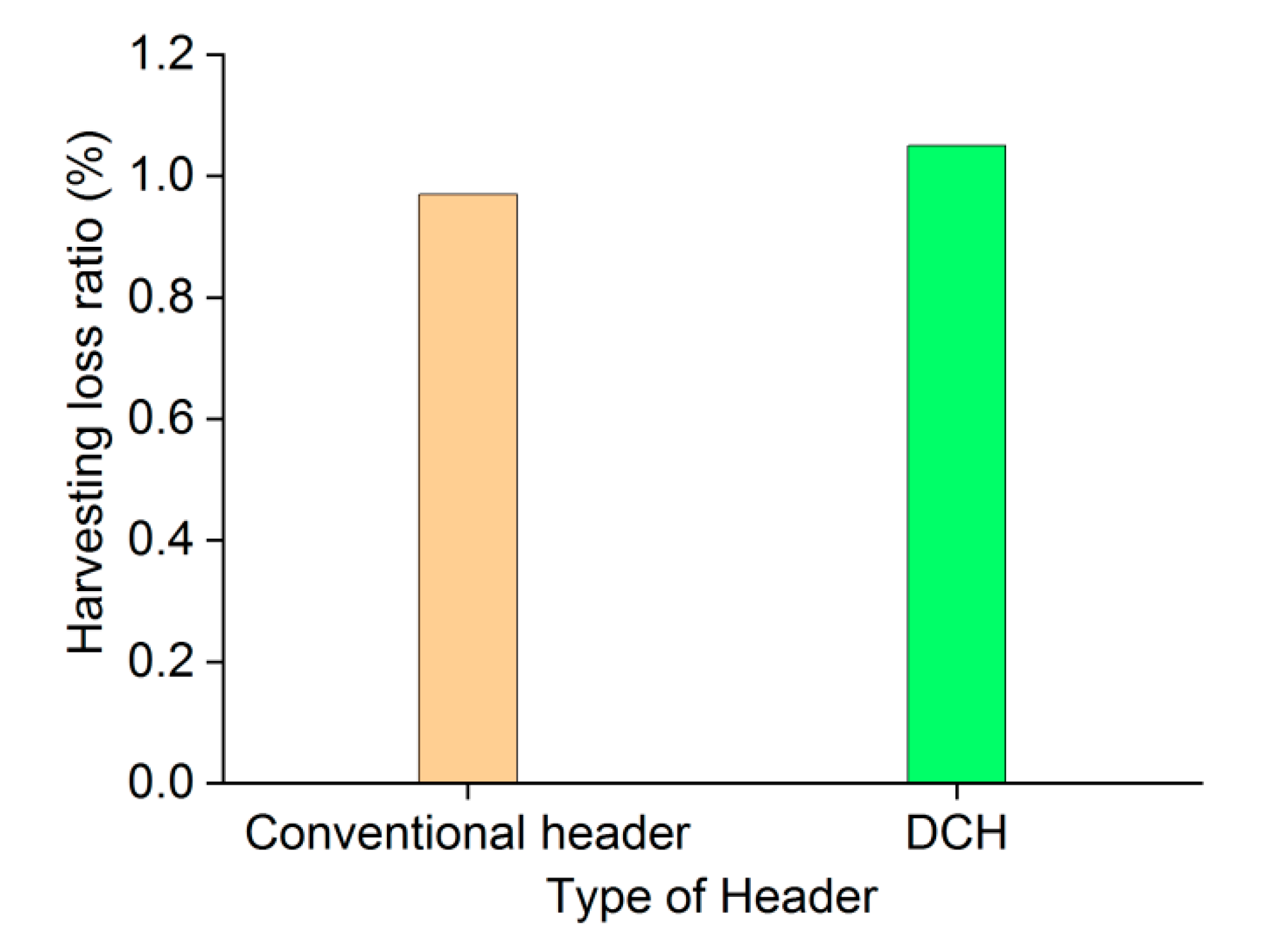
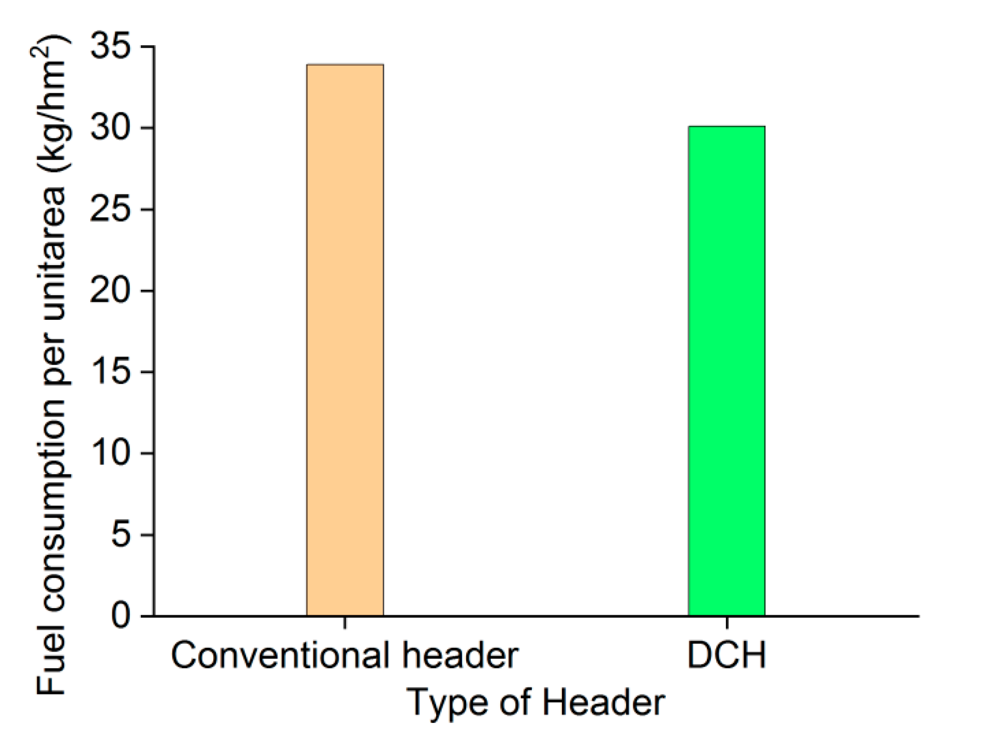
3.3. Field Experiment Analysis

As shown in Figure 14, the loss rate of using the conventional header wheat combine is 0.97%, and the loss rate of using the DCH is 1.05%, but less than 1.2%, which conforms to the relevant national operation quality requirements. The feed rate is reduced for the DCH, and the operating parameters of the threshing and separation device and the cleaning device do not match, increasing the loss rate. Therefore, in the follow-up study, it is also necessary to research the impact of the change in the feed length of the stalk on threshing separation and cleaning performance.
As shown in Table 6, the stubble height of the DCH is 11.02 cm, lower than the stubble height of the conventional header, and it meets the relevant operation quality requirements. The variation coefficient of the stubble height of the DCH is higher than that of the conventional header, indicating that the consistency of the stubble height of the DCH is lower than that of the conventional header. The main reason is that after the upper cutterbars of the DCH cut the upper stalks, the remaining stalks are tilted by the thrust of the header plate before being cut, resulting in uneven cutting after the lower cutterbars cut.
As shown in Figure 15, under the same operating speed, the fuel consumption per unit area of the WCH with a conventional header is 33.9 kg/hm2, and the fuel consumption per unit area of the WCH with a DCH is 30.1 kg/hm2, which reduces the fuel consumption by 11.2%. Compared with the conventional header, the DCH has two layers of cutterbars, and the power consumption of the header is increased. However, at the same operating speed, the length of the stalk fed into the combine becomes shorter, the feed rate decreases, and the power consumption of the conveying, threshing, and cleaning systems decreases, thus reducing the fuel consumption per unit area.

4. Conclusions

(1)
In this paper, a DCH was designed that can only cut the upper part of the wheat plant into the WCH. By reducing the feed length of the stalk, the problems of the wheat combine, such as congestion and high power consumption, are solved, providing a technical reference for the efficient harvest of the wheat combine.
(2)
The effects of feed rate, feed length of the stalk, and speed of the tangential threshing rotor on conveying time were studied using a threshing test bench and optimized to obtain the optimal parameter combination of the test factors: the feed rate was 8 kg/s, the feed length of the stalk was 380 mm, the speed of the tangential threshing rotor was 554 r/min, and the conveying time was 8.089 s. The optimized parameter combination was tested and verified, and the test results show that the relative error with the predicted value was 0.198%, proving the optimized parameters’ reliability.
(3)
Combined with the best feed length of the stalk determined by the bench test, the critical components of the DCH were designed. The movement process of the profiling mechanism was simulated using ADAMS software, which verifies the correctness of the structural design, and the length of the height-limiting connecting rod was determined to be 365 mm.
(4)
The field performance experiment of the DCH of the WCH was carried out, and the average harvest loss rate was 1.05% and the average stubble height was 11.02 cm, which all met the relevant operation quality requirements; at the same operating speed, the fuel consumption was 11.2% less than that of the combine harvester with a conventional header.

Author Contributions

Conceptualization, L.Y. and M.L.; methodology, X.H. and W.W. (Wanzhang Wang); investigation, L.Y., W.W. (Wanzhang Wang) and X.H.; writing—original draft preparation, L.Y., M.L. and X.H.; writing—review and editing, L.Y. and W.W. (Wanzhang Wang); visualization, W.W. (Wenhe Wei) and Z.Q.; funding acquisition, M.L. and W.W. (Wanzhang Wang). All authors have read and agreed to the published version of the manuscript.

Funding

This research was funded by China Agriculture Research System (CARS-03), Henan Province Science and Technology Projects (222102110235), and Henan Province Science and Technology Projects (232102110271).

Institutional Review Board Statement

Not applicable.

Informed Consent Statement

Not applicable.

Data Availability Statement

The data used to support the findings of this study are available from the corresponding author upon request.

Acknowledgments

The authors would like to thank Zhengzhou Zhonglian Harvesting Machinery Co., Ltd., as well as gratefully appreciate the reviewers who provided helpful suggestions for this manuscript.

Conflicts of Interest

The authors declare no conflict of interest. There is no conflict of interest with Zhengzhou Zhonglian Harvesting Machinery Co., Ltd.

References

  1. Fan, C.; Zhang, D.; Yang, L.; Cui, T.; He, X.; Zhao, H. Development and performance evaluation of the electric-hydraulic concave clearance control system based on maize feed rate monitoring. Int. J. Agric. Biol. Eng. 2022, 15, 156–164. [Google Scholar] [CrossRef]
  2. Shamilah, A.M.; Darius, E.P. Actual field speed of rice combine harvester and its influence on grain loss in Malaysian paddy field. J. Saudi Soc. Agric. Sci. 2020, 19, 422–425. [Google Scholar]
  3. Sun, Y.F.; Liu, R.J.; Zhang, M.; Li, M.Z.; Zhang, Z.Q.; Li, H. Design of feed rate monitoring system and estimation method for yield. Comput. Electron. Agric. 2022, 201, 107322. [Google Scholar] [CrossRef]
  4. Zhang, Y.; Chen, D.; Yin, Y.; Wang, X.; Wang, S. Experimental study of feed rate related factors of combine harvester based on grey correlation. IFAC-PapersOnLine 2018, 51, 402–407. [Google Scholar] [CrossRef]
  5. Quick, G.R. Laboratory Analysis of the Combine Header. Trans. ASAE 1973, 16, 5–12. [Google Scholar] [CrossRef]
  6. Nik, M.A.E.; Khademolhosseini, N.; Abbaspour-Fard, M.H.; Mahdinia, A.; Alami-Saied, K. Optimum utilisation of low-capacity combine harvesters in high-yielding wheat farms using multi-criteria decision making. Biosyst. Eng. 2009, 103, 382–388. [Google Scholar] [CrossRef]
  7. Qing, Y.; Li, Y.; Yang, Y.; Xu, L.; Ma, Z. Development and experiments on reel with improved tine trajectory for harvesting oilseed rape. Biosyst. Eng. 2021, 206, 19–31. [Google Scholar] [CrossRef]
  8. Yang, R.; Wang, Z.; Shang, S.; Zhang, J.; Qing, Y.; Zha, X. The design and experimentation of EVPIVS-PID harvesters’ header height control system based on sensor ground profiling monitoring. Agriculture 2022, 12, 282. [Google Scholar] [CrossRef]
  9. Brune, M. Method and Device for Height Control of Headers. Europe Patent No. EP1813144A1, 1 August 2007. [Google Scholar]
  10. Hunt, C.D.; Pankal, M. Header Height Control for Combine Harvester. World Patent NO. WO2021242867A1, 2 December 2021. [Google Scholar]
  11. Zhuang, X.; Li, Y. Header height control strategy of harvester based on robust feedback linearization. Trans. Chin. Soc. Agric. Mach. 2020, 51, 123–130. [Google Scholar]
  12. Xie, Y.; Alleyne, G.; Greer, A.; Deneault, D. Fundamental limits in combine harvester header height control. J. Dyn. Syst. Meas. Control 2013, 135, 034503. [Google Scholar] [CrossRef] [Green Version]
  13. Daniel, M. Header Height Control of Combine Harvester via Robust Feedback Linearization. Master’s Thesis, Iowa State University, Ames, Iowa, 2016. [Google Scholar]
  14. Lopes, G.T.; Magalhaes, P.S.G.; Nobrega, E.G.O. Optimal header height control system for combine harvesters. Biosyst. Eng. 2002, 81, 261–272. [Google Scholar] [CrossRef]
  15. Baumgarten, J.; Wilken, A.; Neitemeier, D.; Bormann, B.; Spiekermann, S.; Irmer, D. Cutting Table Length Adaptation. European Patent NO. EP3858129A1, 8 August 2020. [Google Scholar]
  16. Chen, J.; Wang, S.; Lian, Y. Design and test of header parameter keys electric control adjusting device for rice and wheat combined harvester. Trans. Chin. Soc. Agric. Eng. 2018, 34, 19–26. [Google Scholar]
  17. Honeyman, F.; Dreyer, D.; Glade, M. Auto Reel Height. World Patent NO. WO2019234539A1, 12 December 2019. [Google Scholar]
  18. Li, H.; Wan, X.; Xu, Y.; Jiang, Y.; Liao; Q. Clearance adaptive adjusting mechanism for header screw conveyor of rape combine harvester. Trans. Chin. Soc. Agric. Mach. 2017, 48, 115–122. [Google Scholar]
  19. Li, Y.; Li, Y.; Xu, L.; Hu, B.; Wang, R. Structural parameter optimization of combine harvester cutting bench. Trans. Chin. Soc. Agric. Eng. 2014, 30, 30–37. [Google Scholar]
  20. Xie, H. Design and Experiment of Belt Conveyor Header for Soybean Combine Harvester. Master’s Thesis, Shandong University of Technology, Zibo, China, 2019. [Google Scholar]
  21. Zhang, M.; Jin, M.; Wang, G.; Liang, S.; Wu, C. Design and test of double crank planar five-bar reel in rape windrower. Trans. Chin. Soc. Agric. Mach. 2022, 53, 115–122. [Google Scholar]
  22. Van, V.S.; Vandergucht, S. Agricultural Machine Equipped with Cam Mechanism for Gathering Crop Material. Europe Patent No. EP3064053B1, 13 December 2017. [Google Scholar]
  23. Henry, W.B.; Nielsen, D.C.; Vigil, M.F.; Calderon, F.J.; West, M.S. Proso millet yield and residue mass following direct harvest with a stripper-header. Agronomy 2008, 100, 580–584. [Google Scholar] [CrossRef]
  24. Shelbourne, K.; Pakenham, S. Crop Strippers and Stripper Toothing. Europe Patent No. EP0976315B1, 7 April 2004. [Google Scholar]
  25. Wang, Y. Research on apparatus with two cutters and conveyers in two ways for the combine harvester, Trans. Chin. Soc. Agric. Mach. 1995, 26, 84–89. [Google Scholar]
  26. Dai, F.; Zhao, W.; Han, Z.; Li, X.; Gao, A.; Liu, X. Improvement and experiment on 4gx-100 type wheat harvester for breeding plots. Trans. Chin. Soc. Agric. Mach. 2016, 47, 196–202. [Google Scholar]
  27. Wang, W.; Liu, W.; Yuan, L.; Qu, Z.; Zhang, H.; Zhou, Z. Simulation and experiment of single longitudin axial material movement and establishment of wheat plants model. Trans. Chin. Soc. Agric. Mach. 2020, 51, 170–180. [Google Scholar]
  28. Zhang, H.; Chen, B.; Li, Z.; Zhu, C.; Jin, E.; Qu, Z. Design and simulation analysis of a reverse flexible harvesting device for fresh corn. Agriculture 2022, 12, 1953. [Google Scholar] [CrossRef]
  29. Fu, J.; Zhang, G.; Xie, G.; Wang, Y.; Gao, Y.; Zhou, Y. Development of double-channel feeding harvester for ratoon rice. Trans. Chin. Soc. Agric. Eng. 2020, 36, 11–20. [Google Scholar]
  30. Chinese Academy of Agricultural Mechanization Sciences. Agricultural Machinery Design Manual, 1st ed.; China Agricultural Science and Technology Press: Beijing, China, 2007; pp. 891–904. [Google Scholar]
  31. Technical Specification for Quality Evaluation of Grain Combine Harvesters. NY/T 2090-2011; China Standards Press: Beijing, China, 2011.
  32. Whole-Feed Combine Harvester-Evaluation Index and Measurement Methods for Fuel Consumption. GB/T 29002-2012; China Standards Press: Beijing, China, 2012.
  33. The Work Quality of Grain (Wheat) Combine Harvester. NY/T 995-2006; China Standards Press: Beijing, China, 2006.
  34. Xia, Q.; Zhang, W.; Qi, B.; Wang, Y. Design and experimental study on a new horizontal rotary precision seed metering device for hybrid rice. Agriculture 2023, 13, 158. [Google Scholar] [CrossRef]
Figure 1. Structure of the DCH. (a) Three-dimensional structural diagram of the DCH; (b) Structural diagram of the profiling mechanism. 1. Reel; 2. Screw conveyor; 3. Frame; 4. Inclined conveyor; 5. Height-limiting connecting rod; 6. Swing block; 7. Ground wheel; 8. Lower cutterbar; 9. Fixed beam; 10. Wobble box of the lower cutterbars; 11. Belt expansion device; 12. Support arm; 13. Wobble box of the upper cutterbars; 14. Upper cutterbar.
Agriculture 13 00817 g001
Figure 2. Operation diagram of the DCH.
Agriculture 13 00817 g002
Figure 3. Structural view of the threshing test bench. 1. Frame; 2. Longitudinal axial flow threshing and separating device; 3. Tangential flow threshing and separating device; 4. Material conveying platform; 5. Inclined conveyor; 6. Screw conveyor; 7. Motor; 8. Grain collection boxes; 9. Frequency converter.
Agriculture 13 00817 g003
Figure 4. Conveying performance experiment site. 1. Observation window; 2. High-speed digital camera; 3. Light source; 4. Computer.
Agriculture 13 00817 g004
Figure 5. Conveying time collection. (a) Image at the beginning of the experiment; (b) Image during the stalk conveying; (c) Image at the end of the stalk conveying.
Agriculture 13 00817 g005
Figure 6. Structural diagram of a cam-action reel. 1. Central spoke wheels; 2. Central rotatable shaft; 3. Tine bar; 4. Tine; 5. Crank; 6. Eccentric spoke wheel.
Agriculture 13 00817 g006
Figure 7. Structural diagram of a screw conveyor. (a) Overall structure; (b) Schematic diagram of retractable fingers. 1. Fixed central axis; 2. Screw cylinder; 3. Spiral blade; 4. Crank; 5. Sleeve; 6. Finger seat; 7. Finger; 8. Finger shaft; 9. Conveyor driving shaft.
Agriculture 13 00817 g007
Figure 8. Diagrammatic sketch of a header triangle. 1. Reel; 2. Screw conveyor; 3. Header triangle; 4. Cutterbar.
Agriculture 13 00817 g008
Figure 9. Simulation model.
Agriculture 13 00817 g009
Figure 10. Schematic diagram of the DCH transmission system. 1. Wobble box of the lower cutterbars; 2. Reel; 3. Intermediate shaft of the reel; 4. Screw conveyor; 5. Driving shaft; 6. Wobble box of the upper cutterbars.
Agriculture 13 00817 g010
Figure 11. Effect of the interaction of factors on the conveying time.
Agriculture 13 00817 g011
Figure 12. Motions of the components with the DCH descending. (a) Height change of the upper and lower cutterbars; (b) Length change of the LBA.
Agriculture 13 00817 g012
Figure 13. Motions of the components during harvesting. (a) Height change of the upper and lower cutterbars; (b) Length change of the LBA.
Agriculture 13 00817 g013
Figure 14. Harvesting loss rate of the WCH using different headers.
Agriculture 13 00817 g014
Figure 15. Fuel consumption per unit area of the WCH using different headers.
Agriculture 13 00817 g015
Table 1. Codes of experiment factors.
CodesFactors
Feed Rate A (kg/s)Feed Length of Stalk B (mm)Speed of the Tangential Threshing Rotor C (r/min)
−18300500
09450550
110600600
Table 2. Motion constraints.
NO.ComponentsType of Motion Constraint
1Inclined conveyor—groundRevolute joint
2Header fame—support armRevolute joint
3Header fame—swing blockRevolute joint
4Support arm—height limiting connecting rodRevolute joint
5Height limiting connecting rod—swing blockTranslational joint
6Support arm—Fixed beamFixed joint
7Fixed beam—ground wheelRevolve joint
8Height-limiting block—swing blockContact force
9Ground—ground wheelContact force
Table 3. Transmission ratio of the DCH.
No.ComponentsTransmission Ratio
1Driving shaft—Screw conveyor—Intermediate shaft of the reel13:35:56
2Intermediate shaft of the reel—Reel20:(5~9)
3Driving shaft—Wobbler of the lower cutterbars1:1
4Wobble box of the lower cutterbars—Wobble box of the upper cutterbars1:1
Table 4. Results of the conveying performance test.
No.FactorsConveying Time Y (s)
Feed Rate A (kg/s)Feed Length of Stalk B (mm)Speed of the Tangential Threshing Rotor C (r/min)
1−10−18.53
210−110.735
30−1−19.17
410110.15
51−109.91
611010.625
70008.975
80008.945
9−1108.465
100119.235
11−1−108.125
12−1018.275
1301−110.025
140−118.905
150008.92
Table 5. Variance analysis of the conveying time.
SourceSum of SquaresdfF Valuep-Value
Model9.689426.24<0.0001 **
A8.0513444.5<0.0001 **
B0.631268.37<0.0001 **
C0.451192.07<0.0001 **
AB0.035115.040.0117 *
BC0.027111.650.0190 *
AC0.069129.480.0029 **
A20.17170.780.0001 **
B20.056123.870.0045 **
C20.261110.250.0001 **
Residual0.01254.470.1882
Lack of Fit0.0103
Pure Error 1.517 × 10 3 2
Cor Total8.9914
Note: p < 0.01 (extremely significant, **); p < 0.05 (significant, *).
Table 6. Measurement results of the stubble height.
Type of HeaderStubble Height(cm)Coefficient of Variation (%)
DCH11.023.17
Conventional header11.441.81
Disclaimer/Publisher’s Note: The statements, opinions and data contained in all publications are solely those of the individual author(s) and contributor(s) and not of MDPI and/or the editor(s). MDPI and/or the editor(s) disclaim responsibility for any injury to people or property resulting from any ideas, methods, instructions or products referred to in the content.

