Article

Greenhouse Tomato Picking Robot Chassis

College of Mechanical and Electronic Engineering, Northwest A&F University, Yangling 712100, China
*
Author to whom correspondence should be addressed.
Agriculture 2023, 13(3), 532; https://doi.org/10.3390/agriculture13030532
Submission received: 25 January 2023 / Revised: 18 February 2023 / Accepted: 21 February 2023 / Published: 22 February 2023
(This article belongs to the Section Agricultural Technology)

Abstract

:
In this paper, a greenhouse tomato picking robot chassis that meets the path cruising and setpoint positioning requirements of robots engaged in greenhouse tomato picking operations in China is designed. Based on the trellis-cultivation growing environment of tomatoes, the basic parameters of the chassis and operating space are analyzed to determine the chassis requirements during picking operations. According to these requirements, a kinematic model of a robot chassis with front-wheel steering and rear-wheel driving is constructed, and the planar positioning principle of the chassis is introduced. SOLIDWORKS is used to simulate and design three-dimensional models of the chassis parts, and the ANSYS WORKBENCH plug-in is used to simulate and analyze the bearing performance of key chassis components. ADAMS is used to simulate and evaluate the motion trajectory of the chassis, and the reasonableness of parameters such as the chassis size, selected materials, and load-bearing performance are verified. Based on the simulation results, a physical system is constructed to experimentally verify the straight-line motion and steering performance of the chassis. The experimental results show that the chassis has good cruising and positioning accuracy and meets the specific requirements of path cruising and setpoint positioning in greenhouse tomato picking operations.

1. Introduction

As a key component in greenhouse picking robots, the chassis plays an important role in robot operational performance. Many experts and scholars have researched the operational performance of greenhouse picking robots, including the greenhouse pepper picking robot developed by C. Wouter Bac et al. [1], the greenhouse mushroom picking robot developed by Jiacheng Rong et al. [2], the apple picking robot developed by Abhisesh Silwal et al. [3], and the greenhouse tomato picking robot developed by Qingchun Feng et al. [4]. These picking robots all use a track chassis. These mobile platforms and tracks have large masses, are costly, and require the use of special picking vehicles; moreover, the growing size and pattern in the greenhouse cannot be adjusted according to the particular needs at the time [5,6,7,8]. In addition, the greenhouse cherry tomato picking robot developed by Fatemah Taqi et al. [9], the greenhouse flower picking robot developed by Hiroaki Masuzawa et al. [10], the greenhouse strawberry picking robot developed by Zhang Kailiang et al. [11], the greenhouse tomato picking robot developed by Zhongming Jin et al. [12], and the greenhouse cucumber picking robot developed by Ji Chao et al. all use a crawler chassis [13]. These systems include mobile platforms with good grips and passability on complex roads; however, they are costly, bulky, heavy, and inflexible during steering [14,15,16,17]. Other research examples, such as the greenhouse strawberry picking robots developed by Ya Xiong et al. [18] and Seungmin Woo et al. [19] and the greenhouse tomato picking robots developed by Tao Zhu et al. [20] and Linlu Zu et al. [21], all use wheeled chassis with simple structures, low costs, good load capacities, and steering flexibility. However, these robots can slip on complicated road surfaces [22,23,24].
With an area of up to 11,572,000 m2 and an annual production of over 85.36 million tons, China has the most extensive tomato growing area and largest tomato production in the world [25,26]. Greenhouse-grown tomatoes account for 70.29% of the total vegetables grown, with an area of up to 5.82 million m2 and an annual output of over 60 million tons [27]. However, at present, greenhouse tomato picking is mainly carried out manually, requiring a large amount of automated tomato picking equipment [28,29,30,31,32]. As an important component in tomato picking robots, the automated greenhouse chassis is in great demand in China’s market.
In response to the considerable demand for an automated greenhouse chassis, in this paper, a greenhouse tomato picking robot chassis is designed, and the requirements that need to be met by the chassis to complete automated tomato picking operations in tomato trellis-cultivation growing environments are determined. A kinematic model of a robot chassis with front-wheel steering and rear-wheel driving is constructed, and the planar positioning principle of the chassis is explained. Then, a tomato picking robot chassis is simulated, and the key components of the robot chassis are investigated mechanically to ensure that the chassis has a good load-bearing capacity. The linear walking and steering performance of the chassis is analyzed via simulations, and the acceptability of parameters such as the size and material is verified to guarantee that the chassis meets the specific requirements of path cruising and setpoint positioning in greenhouse tomato picking operations. Finally, prototypes are built, and experiments are conducted both indoors and in greenhouse tomato growing areas to investigate the straight-line travel, steering and setpoint parking abilities of the proposed robot.

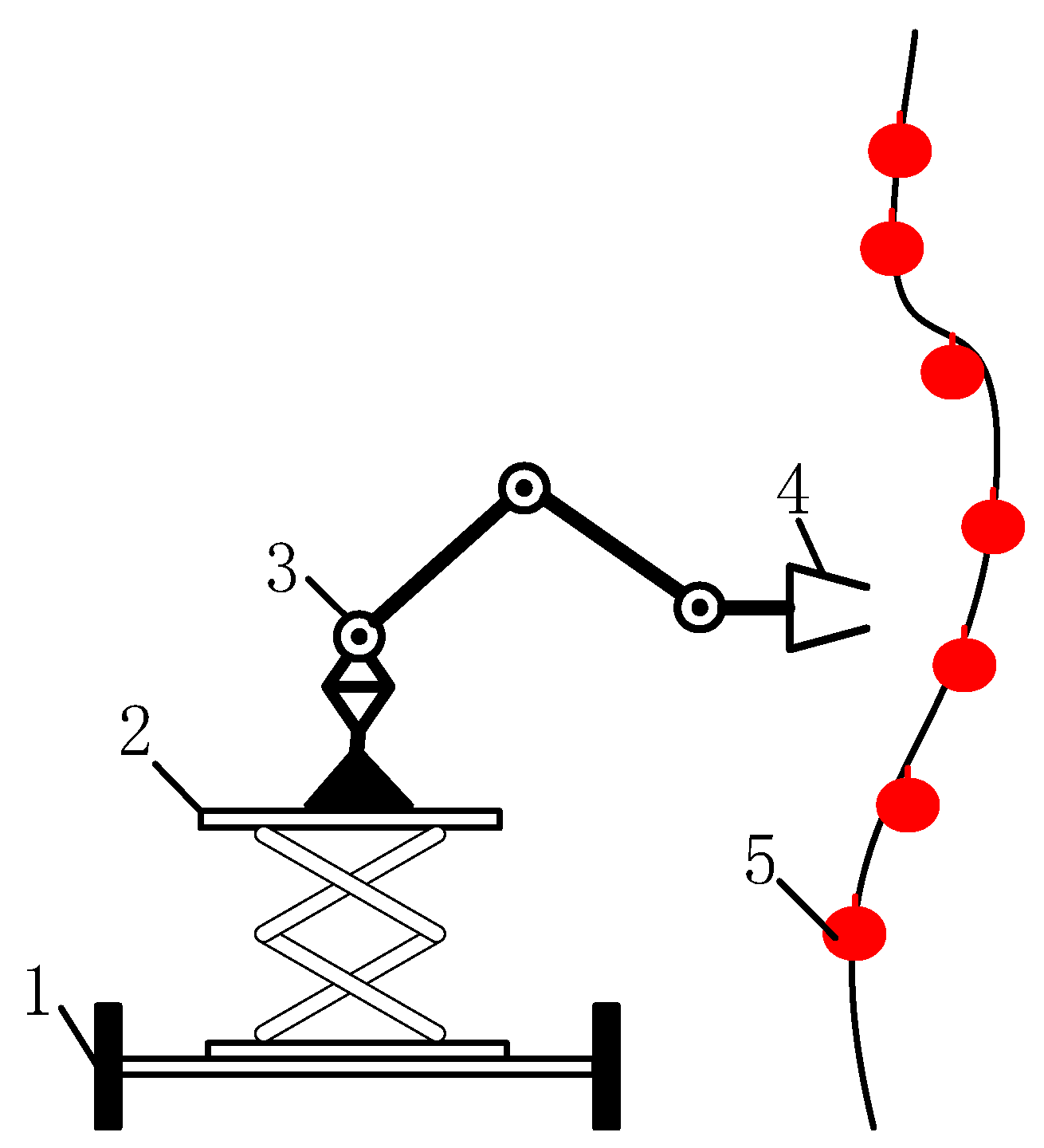
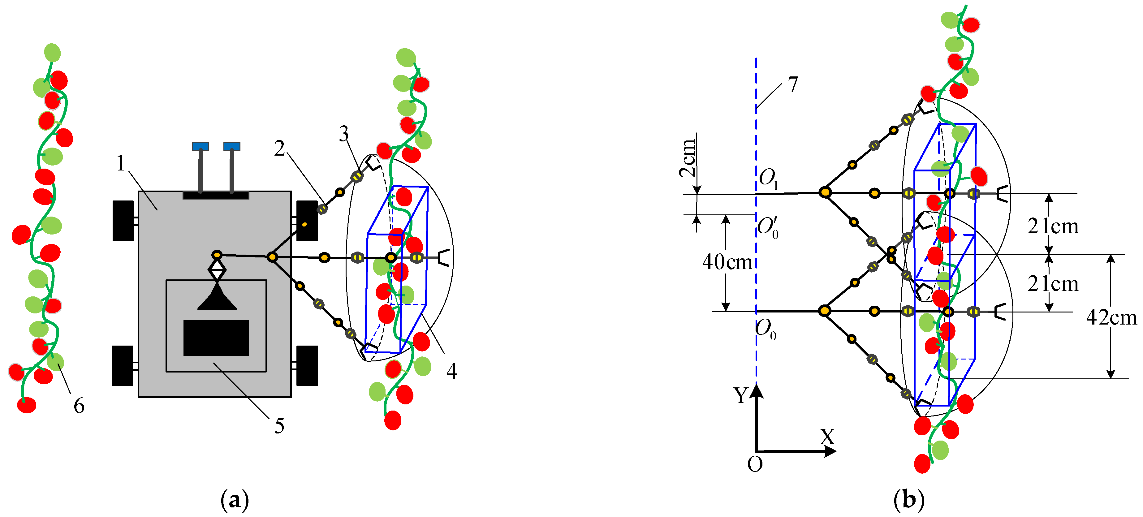
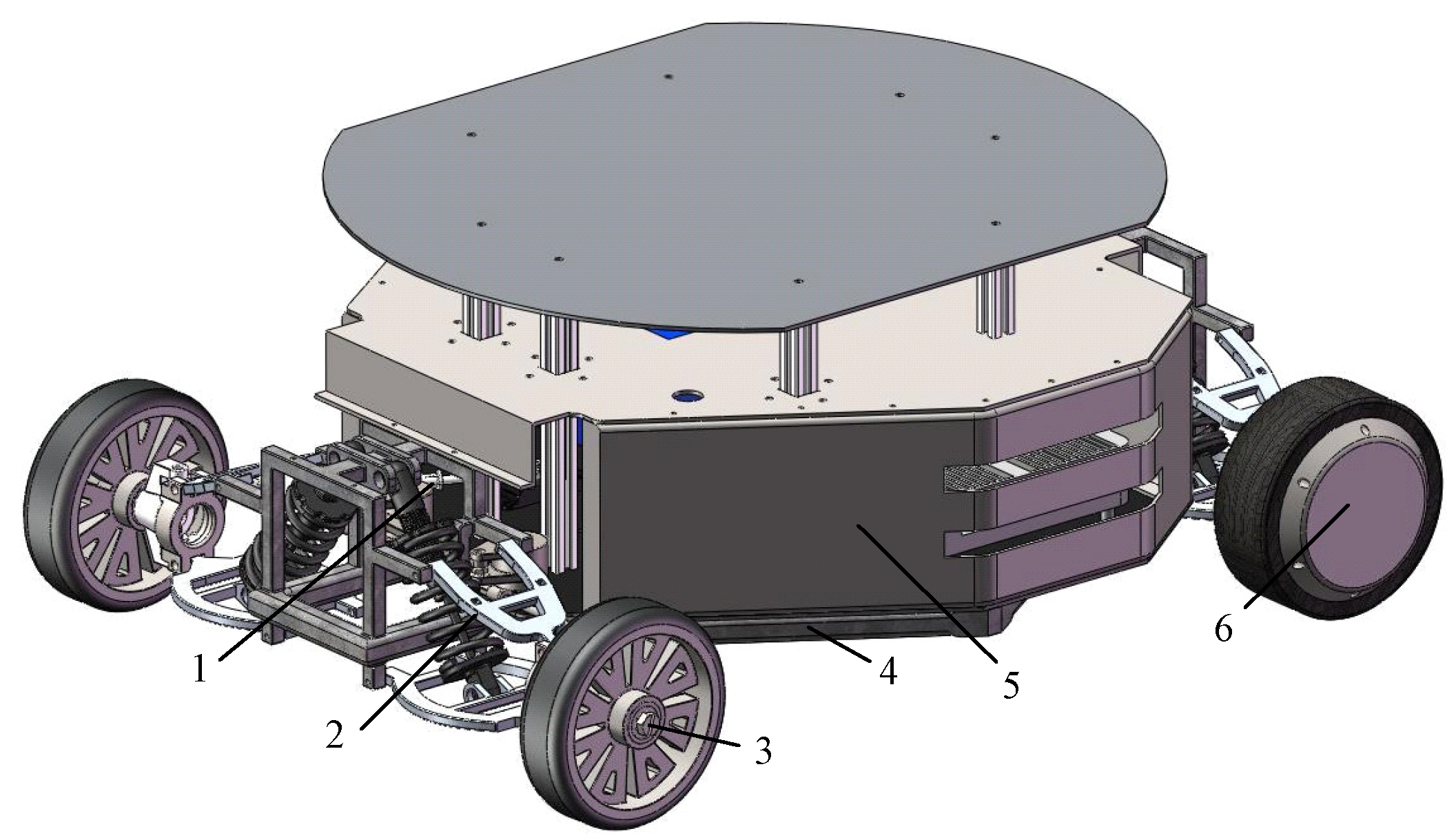
2. Movement Mechanism of the Greenhouse Tomato Picking Robot Chassis

The greenhouse for tomato planting in Shaanxi, China, is shown in Figure 1. The greenhouse was 30 m long and 5.2 m wide, and the environment inside the greenhouse is shown in Figure 1. The tomato plants were 30–160 cm in height, the plant spacing was 26–82 cm, and the ridge spacing was approximately 80 cm.
The tomato picking robot is composed of a wheeled chassis, a lifting platform, a mechanical arm and an end-effector. The operating principle of the proposed robot is shown in Figure 2. According to the greenhouse tomato picking operation environment and agronomic requirements, the chassis of the picking robot adopts a four-wheel wheel mechanism, and the kinematics model is shown in Figure 3. When the front wheel turns, the steering mechanism adopts the Ackerman steering mechanism, and the rear wheel is driven by a hub motor.
According to the above descriptions, the operation flow of the greenhouse tomato picking robot chassis is constructed, as shown in Figure 4, with the robot moving intermittently between the 5.2 m-wide trellis. The robot starts picking at the origin O in the lower left corner of the aisle shown in Figure 4 and stops every 40 cm. After the tomatoes at the current stop are picked, the robot moves to the next stop according to the trajectory shown in Figure 4, and the picking process is repeated until the picking is finished. According to the tomato picking operating environment, operating mechanism, and farmer’s experience, to complete the automated picking operation the picking robot’s traveling ridge should be 80 cm wide. Considering the design allowance, the preliminary width of the chassis was set to 60 cm. To prevent collisions between the robot and plants during the operation, the deviation of the chassis in the X-direction should not exceed  ± 10 cm in a single movement on the ridge path, and the maximum absolute deviation of the robot on the 320 cm straight path should be 10 cm. Similarly, the deviation in the direction perpendicular to the steering trajectory should not exceed 10 cm when the robot turns and moves, and the maximum absolute deviation of the robot during turns and movement should be 10 cm.
Figure 5 shows a schematic diagram of the scope of the robot picking area. The figure demonstrates that the robot positioning spacing is  O 0 O 0 = 40   cm . Assuming the maximum picking range of the manipulator in the Y-direction to be 42 cm, the positioning deviation of the robot in the Y-direction  O 1 O 0  should be kept within  ± 2 cm at each positioning point. In this case, the maximum positioning deviation is  ± 2 cm when the chassis moves straight for 40 cm.
Existing commercially available joint robotic arms have masses of approximately 20 kg, the end claw has a mass of approximately 350 g, and the lifting platform has a mass of approximately 50 kg. The picking robot can carry 50 kg of tomatoes, the weight of the chassis is approximately 55 kg, and the total weight is 175.35 kg [33,34]. Considering the design margin, the preliminary picking robot chassis has a maximum load of 200 kg.
According to the above analysis, the basic requirements of the tomato picking robot chassis can be summarized as follows:
  • The deviation of the robot in the X-direction must not exceed  ± 10 cm when the robot moves straight along a single 320 cm-long ridge track.
  • When the robot turns, the deviation in the direction perpendicular to the turn trajectory must not exceed 10 cm.
  • When the robot stops every 40 cm, the deviation in the X-direction must not exceed  ± 10 cm, and the positioning deviation in the Y-direction must not exceed  ± 2 cm.
  • The robot must be capable of carrying a weight of approximately 200 kg.

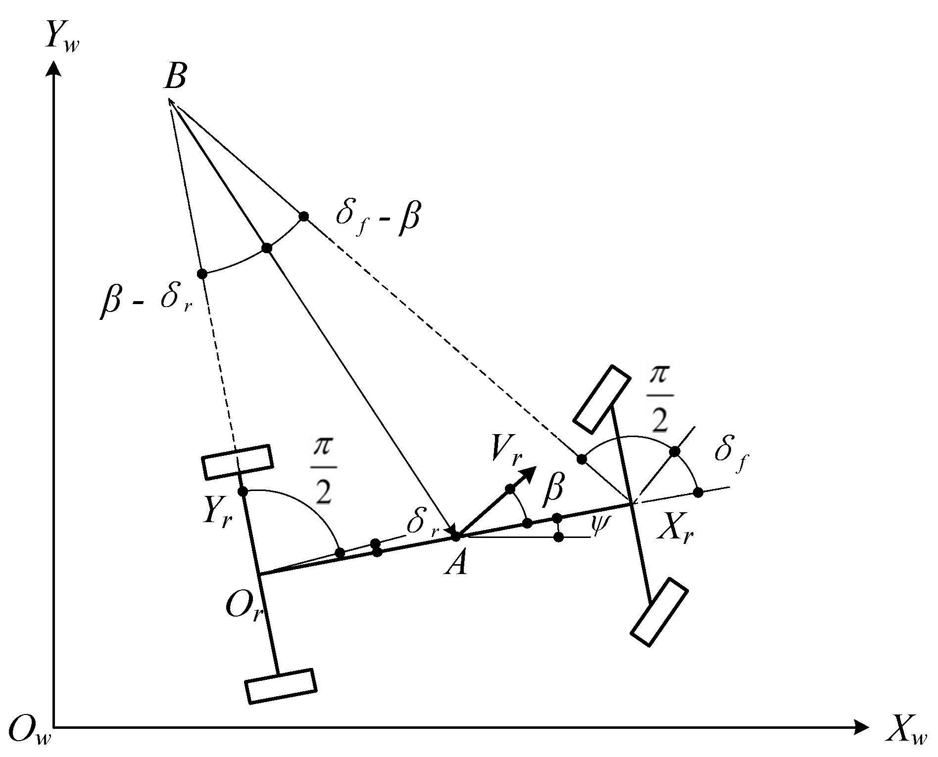
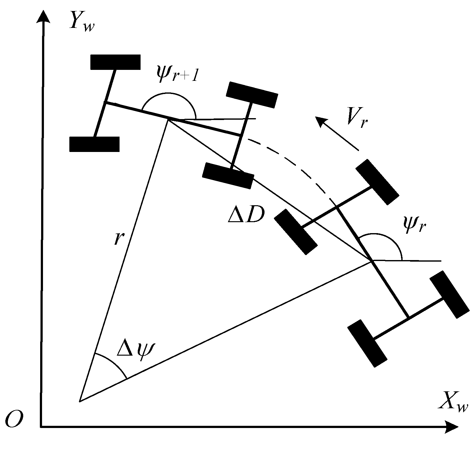
3. Chassis Planar Positioning Principle

A kinematics model of front-wheel steering and rear-wheel driving with the robot chassis is shown in Figure 6. Considering only the motion of the chassis in the two-dimensional plane and ignoring the motion in the Z-axis direction, the world coordinate system  O w X w Y w  and the robot coordinate system  O r X r Y r  can be established. B was taken as the instantaneous rolling center of the chassis, and the line segments  O r B  and  X r B  are perpendicular to the directions of the two rolling wheels. The front-wheel angle is  δ f β  is the slip angle, which refers to the angle between the movement direction of the chassis and its orientation;  ψ  is the heading angle, which refers to the angle between the chassis and the  X r  axis. The center coordinate of the rear acle is  ( X r , Y r ) ψ ˙  is the angular velocity,  V r  is the vehicle speed, and  ω  is the yaw angular velocity. Since the slip angle  β  is extremely small, it is assumed to be 0. Therefore, the kinematics model of the robot chassis is:
X ˙ w Y ˙ w ψ ˙ = cos ψ sin ψ 0 V r + 0 0 1 ω
The kinematics model of the robot chassis is used to establish the odometer model shown in Figure 7, and the pose of the robot chassis after a given time can be obtained. If the linear velocity is  V r , the time is  k , and the angular velocity is  ω , then the distance that the robot moves during this interval is  Δ D   =   V r × d t , and the change in the angle of the robot relative to the origin is  Δ ψ   =   ω   ×   d t . At the time in question, the robot’s pose is  X r =   X r k , Y r ( k ) , ψ r k , and after the time  d t , the robot pose is  X r =   X r k + 1 , Y r ( k + 1 ) , ψ r k + 1 .
The robot’s motion in a very short time interval can be regarded as an arc motion. Because the radius of the arc is  r k = Δ D k Δ ψ k  and  Δ ψ k 0 , the robot’s pose can be obtained from the odometer model as follows:
X r ( k + 1 ) Y r ( k + 1 ) ψ r ( k + 1 ) = X r ( k ) + r k ( sin ( ψ r ( k ) + Δ ψ k ) sin ψ r ( k ) ) Y r ( k )   +   r k ( cos ( ψ r ( k ) + Δ ψ k ) cos ψ r ( k ) ) ψ r ( k ) + Δ ψ k
The robot achieves chassis steering via a steering mechanism driven by the steering engine. The steering principle is shown in Figure 8. The relationship among the steering engine angle  μ , the inner steering wheel angle  α 1  and the outer steering wheel angle  α 2  is formulated as follows [35]:
μ = 0.0001509 α 1 3 0.008748 α 1 2 + 1.047 α 1 0.03573 μ = 0.0001592 α 2 3 0.006714 α 2 2 + 0.944 α 1 + 5.595
To reduce the chassis steering deviation, the four-wheel chassis is simplified into a two-wheel model, as shown in Figure 9, where  δ  is the front wheel angle, L is the wheelbase, R is the radius of the circle to be traveled at this angle,  L d  is the preview distance of the chassis, and  α  is the angle between the current chassis pose and the target trajectory point. The model takes the rear axle of the chassis as the tangent point and controls the rotation angle of the front wheel, thereby allowing the chassis to follow a path through the set trajectory point  ( P x , P y ) .
Figure 8. The steering gear controls the steering mechanism movement.
Agriculture 13 00532 g008
After adding the time variable  t , the relationship between  δ  and  α  can be formulated as:
δ ( t ) = arctan ( 2 L sin ( α ( t ) ) L d )
According to the references, the preview distance is  L d = 0.25 V 2 + 0.2 V + 0.775  [36,37], which can be used to obtain Equation (5), as follows:
δ ( t ) = arctan ( 2 L sin ( α ( t ) ) 0.25 V 2 + 0.2 V + 0.775 )
Considering Equations (3) and (5) and the reference [38,39]:
μ 1 ( t ) = 0.0001509 δ ( t ) 3 0.008748 δ ( t ) 2 + 1.047 δ ( t ) 0.03573 μ 2 ( t ) = 0.0001592 δ ( t ) 3 0.006714 δ ( t ) 2 + 0.944 δ ( t ) + 5.595
Thus, the relationships between the planned waypoint and the angle  δ ( t )  between the current chassis pose and the steering engine angle  μ  are obtained. When the controller provides a command, the engine executes the corresponding action to ensure smooth steering.

4. Chassis Simulation Design and Verification

According to the above analysis and relevant parameters, SOLIDWORKS is used to simulate the design of the greenhouse tomato picking robot chassis, which is 80 cm in length, 60 cm in width and 45 cm in height, as shown in Figure 10, including the frame, car shell, wheeled moving mechanism, broken steering trapezoidal mechanism, and independent suspension mechanism. The various mechanisms of the chassis are connected by bolts. Frame 4 is located at the bottom of the robot chassis and plays an important role in its load-bearing performance. To protect the internal components, car shell 5 was designed for the chassis. During operation, the rotation of driving wheel 6 allows the robot to travel, and the movement of steering mechanism 1 steers the robot.

4.1. Load-Bearing Performance Simulation Analysis

The frame, which is located at the bottom of the robot chassis, plays a crucial role in the load-bearing performance. Therefore, to analyze the load-bearing performance of the robot chassis, the load-bearing performance of the frame must be investigated. The frame material is set as ordinary carbon steel, with a compressive yield strength of 235 MPa, an elastic modulus of  1.67 × 10 11   Pa , a Poisson’s ratio of 0.3, a Young’s modulus of  2 × 10 11   Pa , and a density of 7850  kg / m 3  [40]. A 3D model of a frame with a length of 790 mm, a width of 590 mm, and a height of 140 mm was built in SOLIDWORKS and imported into the WORKBENCH module of ANSYS for deformation and stress simulation analyses. A tetrahedron was used to divide the mesh, and the minimum mesh unit size was set to 10 mm. A stress constraint of a weight of 200 kg was added to the frame, and the combined displacement and stress distribution of the frame under the two working conditions of full-load bending and full-load torsion were simulated and analyzed. The simulation results are shown in Figure 11.
According to the simulation results, the maximum displacements of the frame are 0.55 mm and 0.53 mm under the full-load bending and full-load torsion conditions, respectively. Compared with the frame size, the deformation is small and meets the stiffness requirements of the robot chassis. The maximum stresses on the frame are 84.6 MPa and 90.0 MPa in the two conditions, which are less than the yield strength of ordinary carbon steel and thus satisfy the strength requirements of the robot chassis.
Because the motor connector and lower fork arm are very fragile, the authors also check their mechanical properties. Their material is set as aluminum alloy 7075-T6, with a compressive yield strength of 564 MPa, an elastic modulus of,  7.2 × 10 10   Pa , and a Poisson’s ratio of 0.25 [41]. The WORKBENCH module of ANSYS software was used for deformation and stress simulation analyses. A tetrahedron was used to divide the mesh, and the minimum mesh unit size was set to 10 mm. A stress constraint of a weight of 50 kg was added to the motor connector and lower fork arm, and the combined displacement and stress distribution of the frame were simulated and analyzed. The simulation results are shown in Figure 12.
Figure 11. Simulation results of frame under different working conditions. (a) Distribution of resultant displacement under full load bending; (b) Stress distribution under full load bending; (c) Distribution of resultant displacement under full load torsion; (d) Stress distribution under full load torsion.
Agriculture 13 00532 g011aAgriculture 13 00532 g011b
According to the simulation results, the maximum displacement of the motor connector and the lower fork arm are 0.001 mm and 4.03 mm, respectively, with a small deformation, which satisfies the rigidity requirements of the robot chassis. The maximum stresses of the motor connector and the lower fork arm are 18.9 MPa and 475.7 MPa, respectively, which are less than the yield strength of aluminum alloy 7075-T6 and thus satisfy the strength requirements of the robot chassis. The simulation results show that the chassis can carry 200 kg.

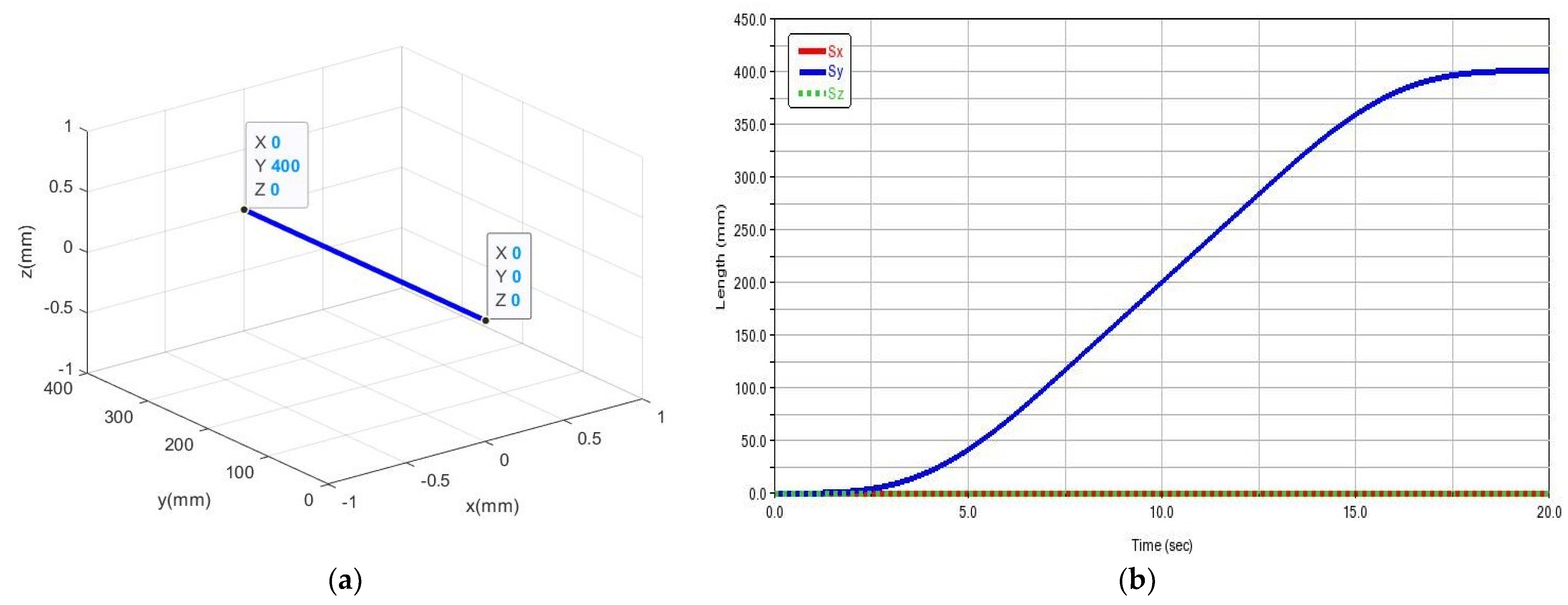
4.2. Motion Trajectory Simulation

In ADAMS, the 3D model of the robot chassis designed with SOLIDWORKS was considered to analyze the motion law of the chassis moving in a straight line. Taking the total time as 20 s and the total number of steps as 500, the speed function of the two driving wheels in the Y-direction is step 5 (time, 0, 0, 8, 33.4) + step 5 (time, 12, 0, 20, −33.4). Finally, the linear motion track and the curves of the displacement S versus time t in the X, Y, and Z directions in the Cartesian coordinate system are obtained, as shown in Figure 13. The figure shows that the robot can complete a straight motion with a length of 320 cm.
Moreover, in ADAMS, the 3D model of the robot chassis constructed by SOLIDWORKS was used to simulate and analyze the steering behavior of the chassis. Taking the total time as 200 s and the total number of steps as 500, the obtained steering trajectory curve is shown in Figure 14. According to the figure, the turning radius of the robot chassis is 40 cm, which means that the robot can complete a circular motion with a turning radius of 40 cm.

5. Experimental Verification and Analysis

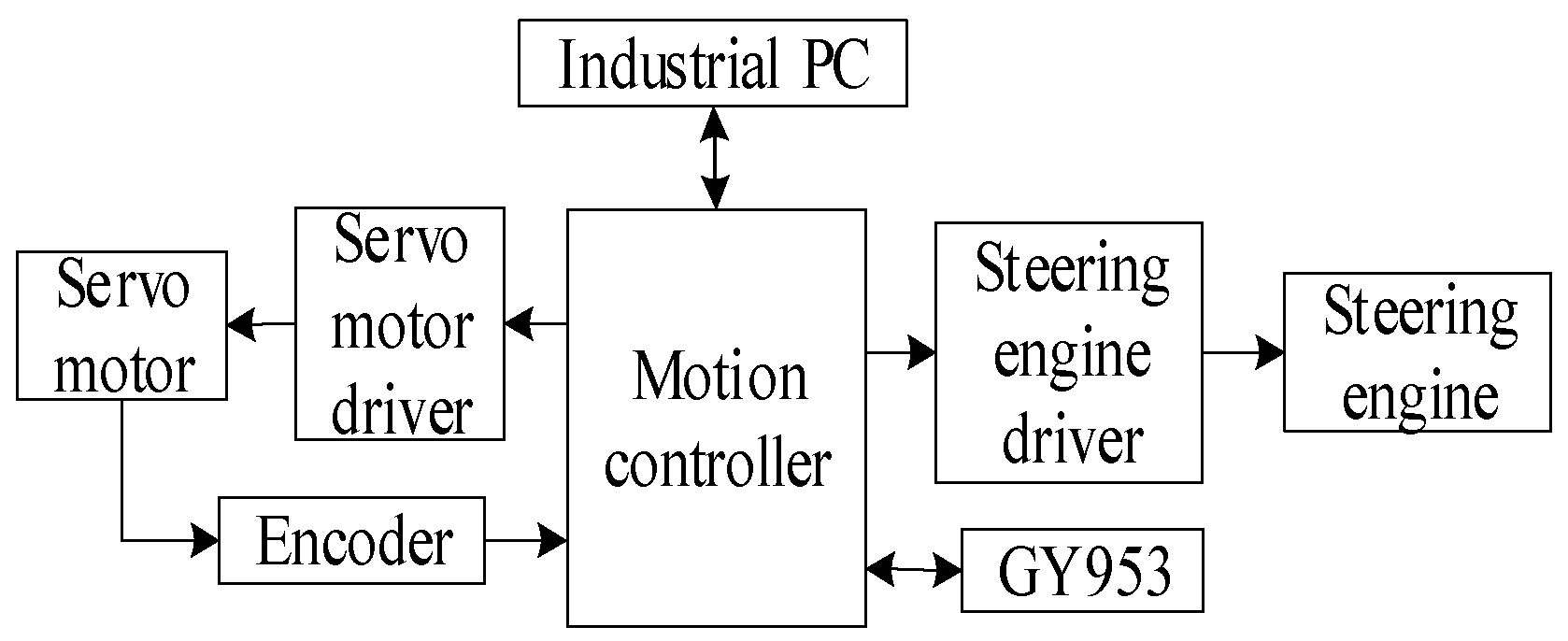
5.1. Physical System Construction

According to the simulation analysis results, the chassis of the greenhouse tomato picking robot was built, as shown in Figure 15. The frame of the robot chassis was made of ordinary carbon steel, and the car shell was made of an aluminum alloy. The other nonstandard components were made of aluminum profiles for laser cutting.
The chassis control system of the greenhouse tomato picking robot is shown in Figure 16. The system includes an industrial computer (GK4000, Shenzhen Chammei High-tech Electronics Co., Ltd., Shenzhen, China), a motion controller (STM32F103VET6, Guangzhou Xingyi Electronic Technology Co., Ltd., Guangzhou, China), a servo motor (Time Chaoqun Technology Co., Ltd., Beijing, China), a servo motor driver (DM-055B, Time Chaoqun Technology Co., Ltd., Beijing, China), a steering engine (DS3218, Premium Robot Co., Ltd., Shenzhen, China), a steering engine driver (LSC-16-V1.3, Magic Robot Official Mall, Shenzhen, China), an incremental photoelectric encoder (OVW2–2MHT, Jiangnan Coding Technology Co., Ltd., Wuxi, China), and a GY953 nine-axis inertial navigation sensor (GY953, Guangyun Electronics GY Series Module Manufacturing Co., Ltd., Guilin, China). The motion controller receives the ideal speed set by the industrial computer and sends this speed value to the motor driver via serial communication to drive the motor to rotate. The encoder detects the actual rotational speed of the motor in real time and transmits this value to the industrial computer through the motion controller. The industrial computer compares the actual rotational speed with the ideal speed. When the deviation is too large, an incremental digital PID algorithm is used to adjust the motor speed to ensure that the actual speed is consistent with the ideal rotational speed. The industrial computer uses Equation (6) to analyze the desired target pose information of the chassis according to the rotation angle of the steering engine and sends the results to the motion controller. Through the steering gear driver, the motion controller drives the steering engine to steer the chassis. The GY953 nine-axis inertial navigation sensor detects the pose of the chassis in real time and sends the pose to the motion controller through serial communication. The motion controller adjusts the traveling direction of the chassis according to the received pose information to ensure that the robot does not yaw when traveling in a straight line.
The correction process when the robot chassis moves in a straight line is shown in Figure 17. The GY953 nine-axis inertial navigation sensor detects and transmits the heading angle in real time during the chassis movement. The heading angle before the chassis movement is denoted as  θ x , and the heading angle as the chassis moves is denoted as  θ s . The angle tolerance threshold is specified as  ε . When  θ s θ x > ε , the robot chassis is in a right-biased state, and the motion controller needs to adjust the motor speed of the left driving wheel to ensure that the robot chassis travels in a straight line. Similarly, when  θ x θ s > ε , the robot chassis is in a left-biased state, and the motion controller needs to adjust the motor speed of the right driving wheel to ensure that the robot travels in a straight line. When  θ s θ x <   ε , the robot chassis does not yaw. During chassis movement, the encoder updates the interrupt count values PR and PL in real time. When their mean values are greater than the preset value X of the chassis travel distance, namely, when  ( P R + P L ) / 2 > X , the motor brakes, and the robot chassis stops moving.

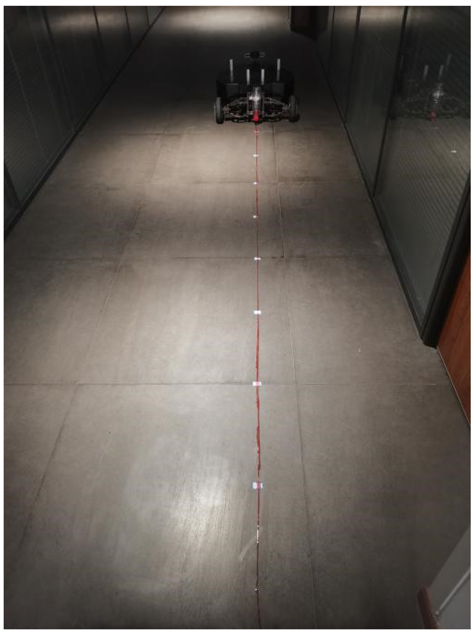
5.2. Experiment and Analysis of Straight-Line Motion in the Laboratory

To verify the actual straight-line traveling performance of the robot chassis, a straight-line motion experiment with the chassis was carried out in a laboratory at Northwest A&F University, and the experimental scene is shown in Figure 18. A plastic bottle with red ink was placed at the center of the back-end position of the chassis, with the top of the bottle facing down and a small hole pierced by a needle on the cap. As the robot chassis moves, red ink flows from the hole, thus leaving a red tracking line on the ground to represent the movement of the chassis.
In the initial position of the robot chassis, the vertical projection point of the bottle on the ground is taken as the origin, the traveling direction of the robot chassis is taken as the Y-axis, and the direction perpendicular to the traveling direction is taken as the X-axis, to establish the plane cartesian coordinate system. The coordinate of the target point that the robot chassis walks toward in a straight line is set as (0, 320), and the coordinate of the actual arrival point is recorded. The experiments were repeated 30 times, and the experimental results are shown in Table 1.
The experimental results were analyzed, and the average transverse deviation in the chassis motion is calculated as
X ¯ = 1 N i = 1 N X i
The average longitudinal deviation in the chassis motion is calculated as
Y ¯ = 1 N i = 1 N Y i
In the equation, N is the number of actual coordinates,  X i  is the abscissa and  Y i  is the ordinate.
According to the data in Table 1 and Equation (7), when the robot chassis travels straight indoors, the average lateral deviation in the deviated trajectory is  X ¯ = 0.78   cm , and the maximum deviation is  X max = 2.1   cm , which satisfy the requirement that the deviation of the robot chassis in the X direction should not exceed  ± 10 cm when the chassis moves along the straight 320 cm long path. Moreover, according to the data in Table 1 and Equation (8), the average longitudinal deviation in the deviated trajectory is  Y ¯ = 0.45   cm , and the maximum deviation is  Y max = ± 1.2   cm , which satisfy the requirement that the deviation in the Y direction should not exceed  ± 2 cm. Therefore, the straight travel deviations of the greenhouse tomato picking robot chassis are within the threshold ranges, demonstrating that the robot chassis has good indoor straight travel performance.

5.3. Experiment and Analysis of Steering in the Laboratory

To verify the actual steering performance of the robot chassis, the steering scene as shown in Figure 19 was built in a laboratory at Northwest A&F University using flowerpots to simulate tomato ridges and PVC pipes to simulate tomato plants. A plastic bottle with red ink was placed at the center of the back end position of the chassis, with the top of the bottle facing down and a small hole pierced by a needle on the cap. As the robot chassis moved, red ink flowed out of the hole, leaving a red track line on the ground to indicate the moving track of the chassis.
At the starting steering point of the robot chassis, the vertical projection point of the bottle on the ground is taken as the origin, the traveling direction of the robot chassis is taken as the Y-axis, and the direction perpendicular to the traveling direction is taken as the X-axis, to establish the plane cartesian coordinate system. A semicircle with a radius of 40 cm is chosen in the coordinate system, and the starting and ending point coordinates are (0, 0) and (80, 0). The semicircular arc is taken as the ideal turning trajectory for the robot chassis. The robot chassis is placed at the origin (0, 0), and the robot is controlled to turn along the semicircular arc. The red ink trace on the ground is taken as the actual track of the chassis during turning. The ideal trajectory is divided into 12 equal, ideal trajectory points. Then, the equally divided points are connected with the center of the circle, and the intersection point between the two lines and the actual trajectory is taken as the actual trajectory point. The coordinates of the ideal and actual trajectory points are both recorded, and the deviation in their distances is calculated according to Equation (9). The results are shown in Table 2. The data in Table 2 were imported into MATLAB for curve fitting, and the ideal, and the actual trajectories of the chassis during turning are presented on two-dimensional planes, as shown in Figure 20.
The distance deviation in the chassis turning motion is calculated as
s = x l x a 2 + y l y a 2
In the equation,  s  is the deviation in the distance,  X l , Y l  are the coordinates of the ideal trajectory point and  X a , Y a  is the deviation in the distance.
Table 2. Experiment data of steering in the laboratory.
NumberThe Coordinates of the Ideal
Trajectory Point/cm
The Coordinates of the Actual Trajectory Point/cmThe Deviation in the
Distance/cm
1(1.4, 10.4)(1.4, 10.4)0
2(5.4, 20.0)(5.8, 19.7)0.50
3(11.7,28.3)(11.1, 28.9)0.85
4(20.0, 34.6)(19.6, 35.2)0.72
5(29.6, 38.6)(29.1, 40.6)2.06
6(40.0, 40.0)(40.0, 43.3)2.60
7(50.4, 38.6)(51.1, 41.0)2.50
8(60.0, 34.6)(60.7,35.7)1.30
9(68.3, 28.3)(69.4, 29.4)1.56
10(74.6, 20.0)(74.9, 20.2)0.36
11(78.6, 10.4)(79.6, 10.7)1.04
12(80.0, 0)(80.3, 0)0.30
Figure 20. The turning trajectories of the chassis in the laboratory.
Agriculture 13 00532 g020
By substituting the data in Table 2 into Equation (7), it can be concluded that when the robot chassis turns indoors, the average deviation in the X direction is 0.50 cm. By substituting the data into Equation (8), the average deviation in the Y direction is calculated to be 0.93 cm. The maximum distance deviation is 2.60 cm, which meets the requirement that the deviation in the direction perpendicular to the turning track should not exceed 10 cm when the chassis turns and moves. In conclusion, the greenhouse tomato picking robot chassis has a small turning deviation, can successfully enter the next ridge, and shows good indoor steering performance.

5.4. Experiment and Analysis of Setpoint Parking in the Laboratory

To verify the setpoint parking performance of the robot chassis, a setpoint parking experiment was carried out in a laboratory at Northwest A&F University. The experiment scene is shown in Figure 21. A plastic bottle with red ink was placed at the center of the back-end position of the chassis, with the top of the bottle facing down and a small hole pierced by a needle on the cap. As the robot chassis moves, red ink flows from the hole, leaving a red track line on the ground that indicates the movement of the chassis.
At the initial position of the robot chassis, the vertical projection point of the bottle on the ground is taken as the origin, the traveling direction of the robot chassis is taken as the Y-axis, and the direction perpendicular to the traveling direction is taken as the X-axis to establish the plane cartesian coordinate system. The straight-line moving distance of the chassis is set to 320 cm, and the robot stops once every 40 cm, yielding a total of eight stops. The coordinates of the target and actual points of the robot chassis during parking are recorded, and the results are shown in Table 3.
According to the data in Table 3 and Equation (7), the average lateral deviation in the deviated trajectory is  X ¯ = 0.6   cm  and the maximum deviation is  X max = 0.9   cm , when the robot chassis stops at a fixed point indoors, which satisfies the requirement that when the chassis stops every 40 cm, the deviation in the X direction should not exceed  ± 10 cm. According to the data in Table 3 and Equation (8), the average longitudinal deviation in the deviated trajectory is  Y ¯ = 0.66   cm , and the maximum deviation is  Y max = 1.3   cm , which satisfies the requirement that when the chassis stops every 40 cm, the deviation in the Y direction should not exceed  ± 2 cm. Therefore, the positioning deviation of the greenhouse tomato picking robot chassis is within the threshold range, demonstrating that the proposed robot performs well at indoor setpoint parking.

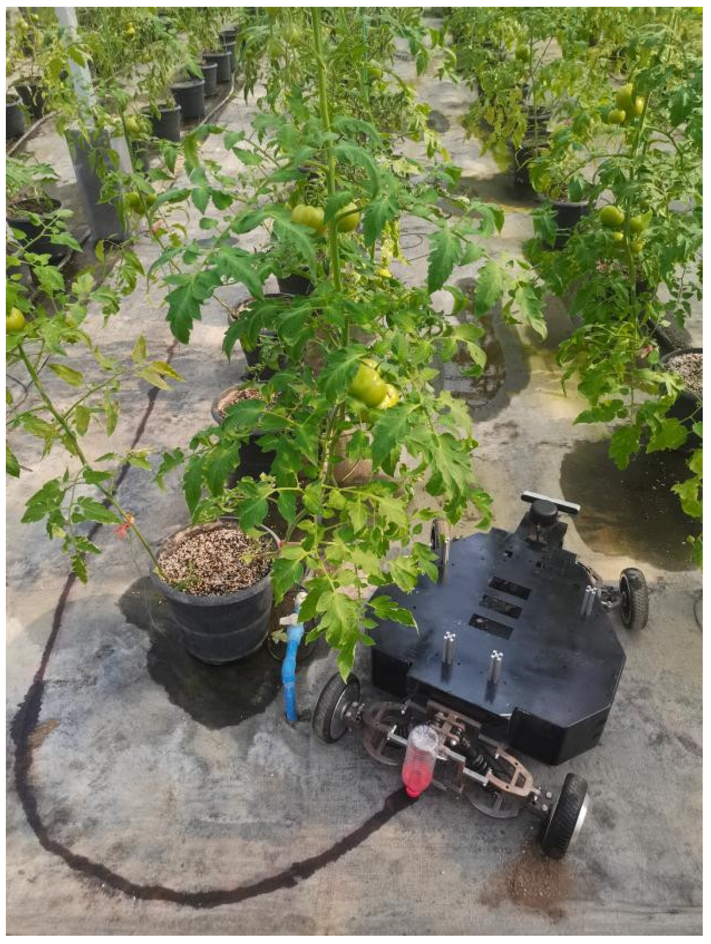
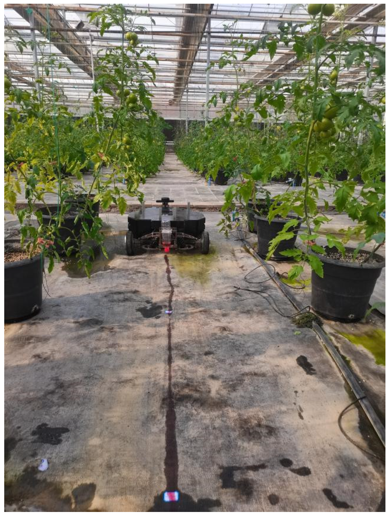
5.5. Experiment and Analysis of Straight-Line Motion in the Greenhouse Tomato Growing Area

Since the robot chassis shows good straight-line traveling performance on flat indoor roads, a straight-line motion experiment was conducted in the greenhouse tomato growing area of Yangling Modern Agriculture Innovation Park in Yangling Demonstration Zone, Xianyang City, Shaanxi Province, and the experimental scene is shown in Figure 22. A plastic bottle with red ink was placed at the center of the back-end position of the chassis, with the top of the bottle facing down and a small hole pierced by a needle on the cap. As the robot chassis moves, red ink flows from the hole, thus leaving a red tracking line on the ground to represent the movement of the chassis.
In the initial position of the robot chassis, the vertical projection point of the bottle on the ground is taken as the origin, the traveling direction of the robot chassis is taken as the Y-axis, and the direction perpendicular to the traveling direction is taken as the X-axis to establish the plane cartesian coordinate system. The coordinates of the target point that the robot chassis walks toward in a straight line are set as (0, 320), and the coordinates of the actual arrival point are recorded. The experiments were repeated 30 times, and the experimental results are shown in Table 4.
According to the data in Table 4 and Equation (7), when the robot chassis travels straight in the greenhouse tomato growing area, the average lateral deviation in the deviated trajectory is  X ¯ = 2.87   cm , and the maximum deviation is  X max = 7.3   cm , which satisfies the requirement that the deviation of the robot chassis in the X direction should not exceed  ± 10 cm when the chassis moves along the straight 320 cm long path. Moreover, according to the data in Table 1 and Equation (8), the average longitudinal deviation in the deviated trajectory is  Y ¯ = 0.80   cm , and the maximum deviation is  Y max = 1.8   cm , which satisfies the requirement that the deviation in the Y direction should not exceed  ± 2 cm. Therefore, the straight-line deviation of the greenhouse tomato picking robot chassis is within the threshold range, demonstrating that the proposed robot has good straight-line walking performance between ridges.

5.6. Experiment and Analysis of Steering in the Greenhouse Tomato Growing Area

Since the chassis has good steering performance on flat indoor roads, a steering experiment was carried out in the greenhouse tomato growing area of Yangling Modern Agriculture Innovation Park in the Yangling Demonstration Zone, Xianyang City, Shaanxi Province, and the experimental scene is shown in Figure 23. A plastic bottle with red ink was placed at the center of the back-end position of the chassis, with the top of the bottle facing down and a small hole pierced by a needle on the cap. As the robot chassis moved, red ink flowed out of the hole, leaving a red track line on the ground to indicate the moving track of the chassis.
At the starting steering point of the robot chassis, the vertical projection point of the bottle on the ground is taken as the origin, the traveling direction of the robot chassis is taken as the Y-axis, and the direction perpendicular to the traveling direction is taken as the X-axis, to establish the plane cartesian coordinate system. A semicircle with a radius of 40 cm is chosen in the coordinate system, and the starting and ending point coordinates are (0, 0) and (80, 0). The semicircular arc is taken as the ideal turning trajectory for the robot chassis. The robot chassis is placed at the origin (0, 0), and the robot is controlled to turn along the semicircular arc. The red ink trace on the ground is taken as the actual track of the chassis during turning. The ideal trajectory is divided into 12 equal ideal trajectory points. Then, the equally divided points are connected with the center of the circle, and the intersection point between the two lines and the actual trajectory is taken as the actual trajectory point. The coordinates of the ideal and actual trajectory points are both recorded, and the deviation in their distances is calculated according to Equation (9). The results are shown in Table 5. The data in Table 5 were imported into MATLAB for curve fitting, and the ideal and actual trajectories of the chassis during turning are presented on two-dimensional planes, as shown in Figure 24.
By substituting the data in Table 5 into Equation (7), it can be concluded that when the robot chassis turns into the greenhouse tomato growing area, the average deviation in the X direction is 1.73 cm. By substituting the data into Equation (8), the average deviation in the Y direction is calculated to be 2.24 cm. The maximum distance deviation is 6.08 cm, which meets the requirement that the deviation in the direction perpendicular to the turning track should not exceed 10 cm when the chassis turns and moves. In conclusion, the greenhouse tomato picking robot chassis has a small steering deviation, can successfully enter the next ridge, and shows good steering performance between ridges.

5.7. Experiment and Analysis of Setpoint Parking in the Greenhouse Tomato Growing Area

Since the robot chassis has good setpoint parking performance on flat indoor roads, a setpoint parking experiment was carried out in the greenhouse tomato growing area of Yangling Modern Agriculture Innovation Park in Yangling Demonstration Zone, Xianyang City, Shaanxi Province, and the experimental scene is shown in Figure 25. A plastic bottle with red ink was placed at the center of the back-end position of the chassis, with the top of the bottle facing down and a small hole pierced by a needle on the cap. As the robot chassis moves, red ink flows from the hole, leaving a red track line on the ground that indicates the movement of the chassis.
At the initial position of the robot chassis, the vertical projection point of the bottle on the ground is taken as the origin, the traveling direction of the robot chassis is taken as the Y-axis, and the direction perpendicular to the traveling direction is taken as the X-axis to establish the plane cartesian coordinate system. The straight-line moving distance of the chassis is set to 320 cm, and the robot stops once every 40 cm, yielding a total of eight stops. The coordinates of the target and actual points of the robot chassis during parking are recorded, and the results are shown in Table 6.
According to the data in Table 6 and Equation (7), the average lateral deviation in the deviated trajectory is  X ¯ = 1.48   cm , and the maximum deviation is  X max = 2.5   cm  when the robot chassis stops at a fixed point in the greenhouse tomato growing area, which satisfies the requirement that when the chassis stops every 40 cm, the deviation in the X direction should not exceed  ± 10 cm. According to the data in Table 6 and Equation (8), the average longitudinal deviation in the deviated trajectory is  Y ¯ = 1.08   cm  and maximum deviation is  Y max = 1.8   cm , which satisfies the requirement that when the chassis stops every 40 cm, the deviation in the Y direction should not exceed  ± 2 cm. Therefore, the positioning deviation of the greenhouse tomato picking robot chassis is within the threshold range, showing that the proposed robot has good setpoint parking performance between ridges.

6. Conclusions

In this paper, a greenhouse tomato picking robot chassis is designed to meet the specific requirements of path cruising and setpoint positioning of robots during automatic tomato picking operations in China. First, based on the trellis-cultivation environment of tomatoes, the basic parameters and operating space of the tomato picking robot chassis are determined, and the chassis requirements are proposed. Then, a kinematics model of a robot chassis with front-wheel steering and rear-wheel driving is constructed to determine the posture of the chassis and transmit the pose in real time to a controller, which inputs the pose information into a PID algorithm to control the motion of the chassis and improve its straight-line walking performance. The Ackermann steering mechanism is implemented to improve the steering accuracy of the chassis. SOLIDWORKS is used to design a 3D model of the chassis; the ANSYS WORKBENCH plug-in is used to simulate and analyze the bearing performance of key chassis components; and ADAMS is used to simulate and analyze the straight-line walking and turning performance of the robot chassis. The reasonableness of parameters such as the chassis size and selected materials and the bearing performance are verified. Finally, the robot chassis prototype is constructed, the motion control system is developed, and the actual motion performance is verified. The experimental results in the laboratory show that when the robot chassis travels in a straight line along a 320 cm-long track, the average deviations in the X and Y directions are 0.78 cm and 0.45 cm, respectively. When the robot chassis travels in a 40 cm-radius turn, the average deviations in the X and Y directions are 0.50 cm and 0.93 cm, respectively. Moreover, when the robot chassis travels in a 40 cm zone, the average deviations in the X and Y directions are 0.60 cm and 0.66 cm, respectively. The experimental results in a greenhouse tomato growing area show that the average deviations in the X-axis and Y-axis directions are 2.87 cm and 0.80 cm when the robot chassis travels along a straight 320 cm-long path; the average deviations in the X and Y directions are 1.73 cm and 2.24 cm when the robot travels in a 40 cm-radius turn; and the average deviations in the X- and Y-directions are 1.48 cm and 1.08 cm when the robot travels in a 40 cm zone. The experimental results show that the average motion deviations of the robot chassis in the X-axis and Y-axis directions are small during straight line, turning, and positioning motions, which proves that the robot chassis has good kinematic performance.
This study presents a novel chassis design for automatic greenhouse equipment that can be widely used in other automatic greenhouse operations, such as spraying, fertilization, and material transport. Thus, the proposed design has high practical value and broad development prospects. Additionally, the designed chassis has a certain significance for designing chassis systems for other greenhouse robots. Due to time and cost limitations, there is a certain error between the angle of the robot chassis designed in this paper and the ideal Ackerman angle. In future work, the picking performance of the robot chassis can be further improved by optimizing its structure.

Author Contributions

Conceptualization, L.S.; methodology, R.L.; software, K.L. (Kenan Liu); validation, K.L. (Kai Li); formal analysis, L.L.; investigation, L.S.; resources, L.L.; data curation, R.L.; writing—original draft preparation, L.S.; writing—review and editing, Y.S.; visualization, K.L. (Kenan Liu); supervision, Y.S.; project administration, Y.S.; funding acquisition, Y.S. All authors have read and agreed to the published version of the manuscript.

Funding

This research was funded by the Shaanxi Province Key Research and Development Projects of China (2019NY-171).

Institutional Review Board Statement

Not applicable.

Informed Consent Statement

Not applicable.

Data Availability Statement

Not applicable.

Conflicts of Interest

The authors declare no conflict of interest.

References

  1. Bac, C.W.; Hemming, J.; Tuijl, B.A.; Barth, R.; Wais, E.; Henten, E.J. Performance Evaluation of a Harvesting Robot for Sweet Pepper. J. Field Robot. 2017, 34, 1123–1139. [Google Scholar] [CrossRef]
  2. Rong, J.C.; Wang, P.B.; Yang, Q.; Huang, F. A Field-Tested Harvesting Robot for Oyster Mushroom in Greenhouse. Agronomy 2021, 11, 1210. [Google Scholar] [CrossRef]
  3. Silwal, A.; Davidson, J.R.; Karkee, M.; Mo, C.; Zhang, Q.; Lewis, K. Design, integration, and field evaluation of a robotic apple harvester. J. Field Robot. 2017, 34, 1140–1159. [Google Scholar] [CrossRef]
  4. Feng, Q.C.; Zou, W.; Fan, P.F.; Zhang, C.F.; Wang, X. Design and test of robotic harvesting system for cherry tomato. Int. J. Agric. Biol. Eng. 2018, 11, 96–100. [Google Scholar] [CrossRef]
  5. Hayashi, S.; Yamamoto, S.; Tsubota, S.; Ochiai, Y.; Kobayashi, K.; Kamata, J.; Kurita, M.; Inazumi, H.; Peter, R. Automation technologies for strawberry harvesting and packing operations in Japan. J. Berry Res. 2014, 4, 19–27. [Google Scholar] [CrossRef] [Green Version]
  6. Liu, J.Z. Research Progress Analysis of Robotic Harvesting Technologies in Greenhouse. Trans. Chin. Soc. Agric. Mach. 2017, 48, 1–18. [Google Scholar] [CrossRef]
  7. Mishra, H.; Giordano, A.M.; Stefano, M.D.; Lampariello, R.; Ott, C. Inertia-Decoupled Equations for Hardware-in-the-Loop Simulation of an Orbital Robot with External Forces. In Proceedings of the 2020 IEEE/RSJ International Conference on Intelligent Robots and Systems (IROS), Las Vegas, NV, USA, 24 October 2020–24 January 2021; IEEE: Piscataway, NJ, USA, 2020; pp. 1879–1886. [Google Scholar] [CrossRef]
  8. Ringdahl, O.; Kurtser, P.; Edan, Y. Evaluation of approach strategies for harvesting robots: Case study of sweet pepper harvesting. J. Intell. Robot. Syst. 2019, 95, 149–164. [Google Scholar] [CrossRef] [Green Version]
  9. Taqi, F.; Al-Langawi, F.; Abdulraheem, H.; EI-Abd, M. A cherry-tomato harvesting robot. In Proceedings of the 2017 18th International Conference on Advanced Robotics (ICAR), Hong Kong, China, 10–12 July 2017; IEEE: Piscataway, NJ, USA, 2017; pp. 463–468. [Google Scholar] [CrossRef]
  10. Masuzawa, H.; Miura, J.; Oishi, S. Development of a mobile robot for harvest support in greenhouse horticulture—Person following and mapping. In Proceedings of the 2017 IEEE/SICE International Symposium on System Integration (SII), Taipei, Taiwan, 11–14 December 2017; IEEE: Piscataway, NJ, USA, 2017; pp. 541–546. [Google Scholar] [CrossRef]
  11. Zhang, K.L.; Yang, L.; Wang, L.J.; Zhang, L.X.; Zhang, T.Z. Design and Experiment of Elevated Substrate Culture Strawberry Picking Robot. Trans. Chin. Soc. Agric. Mach. 2012, 43, 165–172. [Google Scholar] [CrossRef]
  12. Jin, Z.M.; Sun, W.; Zhang, J.; Shen, C.; Zhang, H.Y.; Han, S.Q. Intelligent Tomato Picking Robot System Based on Multimodal Depth Feature Analysis Method. IOP Conf. Ser. Earth Environ. Sci. 2020, 440, 042074. [Google Scholar] [CrossRef]
  13. Ji, C.; Feng, Q.C.; Yuan, T.; Tan, Y.Z.; Li, W. Development and Performance Analysis on Cucumber Harvesting Robot System in Greenhouse. Robot 2011, 33, 726–730. [Google Scholar] [CrossRef]
  14. Tang, Z.; Zhang, B.; Liu, X.; Ren, H.; Li, X.Y.; Li, Y.M. Structural model and bundling capacity of crawler picking and baling machine for straw wasted in field. Comput. Electron. Agric. 2020, 175, 105622. [Google Scholar] [CrossRef]
  15. Fujita, T.; Segawa, W. Object gripping and lifting based on plane detection by tracked mobile robot with two manipulators. In Proceedings of the 2017 18th International Conference on Advanced Robotics (ICAR), Hong Kong, China, 10–12 July 2017; IEEE: Piscataway, NJ, USA, 2017; pp. 412–416. [Google Scholar] [CrossRef]
  16. Xing, Z.Z.; Yu, L.Z.; Fan, L.; Shang, L.; Zhang, X.L. Structure design and type selection of a crawler manipulator chassis. J. Phys. Conf. Ser. 2021, 1885, 052028. [Google Scholar] [CrossRef]
  17. Barakat, M.H.; Ammar, H.H.; Elsamanty, M. Experimental Path tracking optimization and control of a nonlinear skid steering tracked mobile robot. In Proceedings of the 2020 2nd Novel Intelligent and Leading Emerging Sciences Conference (NILES), Giza, Egypt, 24–26 October 2020; IEEE: Piscataway, NJ, USA, 2020; pp. 434–438. [Google Scholar] [CrossRef]
  18. Xiong, Y.; Peng, C.; Grimstad, L.; From, P.J.; Isler, V. Development and field evaluation of a strawberry harvesting robot with a cable-driven gripper. Comput. Electron. Agric. 2019, 157, 392–402. [Google Scholar] [CrossRef]
  19. Woo, S.; Uyeh, D.D.; Kim, J.; Kim, Y.; Kang, S.; Kim, K.C.; Lee, S.Y.; Ha, Y.; Lee, W.S. Analyses of Work Efficiency of a Strawberry-Harvesting Robot in an Automated Greenhouse. Agronomy 2020, 10, 1751. [Google Scholar] [CrossRef]
  20. Zhu, T.; Xiang, J. Chassis Design of Tomato Picking Robot in the Greenhouse. J. Phys. Conf. Ser. 2021, 2136, 012047. [Google Scholar] [CrossRef]
  21. Zu, L.L.; Han, M.Z.; Liu, J.Q.; Liu, P.Z.; Li, T.; Su, F. Design and Experiment of Nondestructive Post-Harvest Device for Tomatoes. Agriculture 2022, 12, 1233. [Google Scholar] [CrossRef]
  22. Sun, W.C.; Li, S.G.; Wang, W.Q.; Zhao, P.J.; Yang, R.Q. Design of Chassis and Kinematics Research of Wheeled Robot. In Proceedings of the 2020 IEEE 4th Information Technology, Networking, Electronic and Automation Control Conference (ITNEC), Chongqing, China, 12–14 June 2020; IEEE: Piscataway, NJ, USA, 2020; pp. 2405–2408. [Google Scholar] [CrossRef]
  23. Kang, S.M.; Sung, Y.W. A Four-Wheeled Mobile Robot with Omnidirectionality. J. Inst. Converg. Signal Process. 2022, 23, 21–27. [Google Scholar] [CrossRef]
  24. Hrbáček, J.; Ripel, T.; Krejsa, J. Ackermann mobile robot chassis with independent rear wheel drives. In Proceedings of the Proceedings of 14th International Power Electronics and Motion Control Conference EPE-PEMC 2010, Ohrid, Macedonia, 6–8 September 2010; IEEE: Piscataway, NJ, USA, 2010; p. T5-46–T5-51. [Google Scholar] [CrossRef]
  25. Xu, C.; Xiong, Z.; Jiang, X.P.; Deng, M.; Huang, G.C. Design and Research of the Cluster Tomato Picking Robot. Mod. Agric. Equip. 2021, 42, 15–23. [Google Scholar] [CrossRef]
  26. Li, Y.L.; Wen, X.G. Analysis on the difference of greenhouse tomato production between China and the Netherlands. Appl. Eng. Technol. 2018, 38, 10–14. [Google Scholar] [CrossRef]
  27. Wang, Z.H.; Xun, Y.; Wang, Y.K.; Yang, Q.H. Review of smart robots for fruit and vegetable picking in agriculture. Int. J. Agric. Biol. Eng. 2022, 15, 33–54. [Google Scholar] [CrossRef]
  28. Pang, J.; Han, Q.C.; Zhou, S.; Li, H.H.; Song, J.W.; Liu, H. The Integrative Effects of Irrigation and Aeration on Growth and Water Use Efficiency of Greenhouse Tomato. J. Irrig. Drain. 2022, 41, 87–94. [Google Scholar] [CrossRef]
  29. Hou, Z.L.; Li, Z.G.; Fadiji, T.B.; Fu, J. Soft grasping mechanism of human fingers for tomato-picking bionic robots. Comput. Electron. Agric. 2021, 182, 106010. [Google Scholar] [CrossRef]
  30. Wang, Z.H.; Chen, X.J.; Lv, D.S.; Li, W.H.; Wang, T.Y.; Wei, C.L. Effects of water and fertilizer coupling on the yield and quality of processing tomato under aerated drip irrigation. Trans. Chin. Soc. Agric. Eng. 2020, 36, 66–75. [Google Scholar] [CrossRef]
  31. Li, H.Y.; Sun, Q.; Liu, N.; Liu, S.L.; Shi, Y.G. A Novel Tomato Volume Measurement Method based on Machine Vision. Teh. Vjesn. 2021, 28, 1674–1680. [Google Scholar] [CrossRef]
  32. Xu, B.; Cui, X.; Ji, W.; Yuan, H.; Wang, J.C. Apple Grading Method Design and Implementation for Automatic Grader Based on Improved YOLOv5. Agriculture 2023, 13, 124. [Google Scholar] [CrossRef]
  33. Wu, J.H.; Zhang, Y.; Zhang, S.H.; Wang, H.J.; Liu, L.; Shi, Y.G. Simulation Design of a Tomato Picking Manipulator. Teh. Vjesn. 2021, 28, 1253–1261. [Google Scholar] [CrossRef]
  34. Shi, Y.G.; Zhang, W.; Yang, T.; Wang, Y.; Liu, L.; Cui, Y.J. Flexible joints of picking manipulator based on current feedback. IEEE Access 2020, 8, 85329–85338. [Google Scholar] [CrossRef]
  35. Gao, H.; Liang, H.W. Simulation and Real-vehicle experiment of automatic parking system based on Multi-sensors and Multi-path planning. Autom. Instrum. 2011, 162–165, 168. [Google Scholar] [CrossRef]
  36. Wei, L.T.; Wang, X.Y.; Qiu, B.; Li, L.; Zhou, D.L.; Lin, J.G. Tracking and Collision Avoidance of Autonomous Vehicle Based on Adaptive Preview Path. J. Mech. Eng. 2022, 58, 184–193. [Google Scholar] [CrossRef]
  37. Zhao, Z.G.; Zhou, L.J.; Zhu, Q. Preview Distance Adaptive Optimization for the Path Tracking Control of Unmanned Vehicle. J. Mech. Eng. 2018, 54, 166–173. [Google Scholar] [CrossRef]
  38. Santhanakrishnan, M.N.; Rayappan, J.B.; Kannan, R. Implementation of extended Kalman filter-based simultaneous localization and mapping: A point feature approach. Sādhanā 2017, 42, 1495–1504. [Google Scholar] [CrossRef]
  39. Ahn, J.; Shin, S.; Kim, M.; Park, J. Accurate path tracking by adjusting look-ahead point in pure pursuit method. Int. J. Automot. Technol. 2021, 22, 119–129. [Google Scholar] [CrossRef]
  40. Zhang, J.; Xie, Y.L. Optimization of lightweight frame for a micro-electric commercial vehicle. Mech. Electr. Eng. Mag. 2020, 37, 283–287. [Google Scholar] [CrossRef]
  41. Wang, H.; Gao, L.; Chen, M.H.; Jin, L.L. Deep Drawing of A7075 with T6 Temper at Elevated Temperature. China Mech. Eng. 2012, 23, 232–235. [Google Scholar] [CrossRef]
Figure 1. Solar greenhouse. (a) The appearance of the solar greenhouse; (b) Tomato planting environment in greenhouse.
Agriculture 13 00532 g001
Figure 2. Tomato-picking robot. 1:chassis; 2: lift platform; 3: mechanical arm; 4: end-effector; 5: fruit.
Agriculture 13 00532 g002
Figure 3. Movement principle of four-wheel wheel mechanism.
Agriculture 13 00532 g003
Figure 4. Schematic diagram of the intermittent mobile operation of the robotic pick. 1: chassis operation docking point; 2: chassis cruise path; 3: tomato plant planting line; 4: the picking robot’s traveling ridge; 5: tomato-picking robot; 6: arch bracket.
Agriculture 13 00532 g004
Figure 5. Schematic diagram of the working space of the picking robotic arm. (a) Individual picking areas; (b) Two adjacent picking areas. 1: wheeled chassis; 2: mechanical arm; 3: end-effector; 4: fan-shaped picking operation space area; 5: lift platform; 6: fruit; 7: walking ridge road;  O 0 O 0 : ideal stop point;  O 1 : actual stop point.
Agriculture 13 00532 g005
Figure 6. Kinematic model of robot chassis.
Agriculture 13 00532 g006
Figure 7. Mileometer model.
Agriculture 13 00532 g007
Figure 9. A Schematic diagram of the simplified two-round model.
Agriculture 13 00532 g009
Figure 10. Simulation design diagram of the tomato picking robot chassis. 1: Steering mechanism; 2: suspension mechanism; 3: driven wheel; 4: frame; 5: car shell; 6: driving wheel.
Agriculture 13 00532 g010
Figure 12. Simulation results of the motor connector and lower fork arm. (a) Distribution of resultant displacement of motor connector; (b) Stress distribution of motor connector; (c) Distribution of resultant displacement of lower fork arm; (d) Stress distribution of lower fork arm.
Agriculture 13 00532 g012
Figure 13. The motion parameter curves of the chassis straight motion. (a) Trajectory curve; (b) displacement curve.
Agriculture 13 00532 g013
Figure 14. Chassis steering track curve.
Agriculture 13 00532 g014
Figure 15. Assembly drawing of the test prototype.
Agriculture 13 00532 g015
Figure 16. The chassis control system of the greenhouse tomato picking robot.
Agriculture 13 00532 g016
Figure 17. The correction process when the robot chassis moves in a straight line.
Agriculture 13 00532 g017
Figure 18. Experiment scene of straight-line motion in the laboratory.
Agriculture 13 00532 g018
Figure 19. Experiment scene of steering in the laboratory.
Agriculture 13 00532 g019
Figure 21. Experiment scene of setpoint parking in the laboratory.
Agriculture 13 00532 g021
Figure 22. Experiment scene of straight-line motion in the greenhouse tomato growing area.
Agriculture 13 00532 g022
Figure 23. Experiment scene of steering in the greenhouse tomato growing area.
Agriculture 13 00532 g023
Figure 24. The turning trajectories of the chassis in the greenhouse tomato growing area.
Agriculture 13 00532 g024
Figure 25. Experiment scene of setpoint parking in the greenhouse tomato growing area.
Agriculture 13 00532 g025
Table 1. Experiment data of straight-line motion in the laboratory.
NumberThe Coordinate of the Actual Point/cmNumberThe Coordinate of the Actual Point/cm
1(0.7, 320.2)16(0.2, 319.7)
2(1.2, 318.9)17(−0.3, 319.8)
3(0.7, 320.5)18(−0.5, 320.4)
4(−2.1, 320.4)19(1.2, 321.1)
5(−0.7, 319.9)20(−0.6, 320.4)
6(−0.5, 319.7)21(1.9, 320.1)
7(−0.2, 320.9)22(−0.2, 319.9)
8(1.6, 319.5)23(0.5, 318.9)
9(0.8, 318.8)24(−0.2, 320.0)
10(−1.9, 320.9)25(−0.3, 319.7)
11(−1.1, 319.5)26(−0.6, 320.1)
12(0.0, 320.4)27(0.4, 321.2)
13(1.3, 319.9)28(−1.3, 320.4)
14(−1.6, 320.2)29(0.3, 320.2)
15(0.3, 320.1)30(−0.2, 319.9)
Table 3. Experiment data of setpoint parking in the laboratory.
NumberThe Coordinate of the Target Point/cmThe Coordinate of the Actual Point/cm
1(0, 40)(0.3, 40.4)
2(0, 80)(0.5, 79.3)
3(0, 120)(−0.2, 119.8)
4(0, 160)(0.6, 160.8)
5(0, 200)(0.9, 199.7)
6(0, 240)(−0.6, 240.5)
7(0, 280)(0.8, 281.1)
8(0, 320)(0.9, 321.3)
Table 4. Experiment data of straight-line motion in the greenhouse tomato growing area.
NumberThe Coordinate of the Actual Point/cmNumberThe Coordinate of the Actual Point/cm
1(2.7, 321.2)16(1.4, 320.1)
2(3.5, 318.4)17(−0.3, 320.3)
3(1.5, 321.5)18(−2.5, 319.6)
4(3.4, 320.4)19(−2.1, 318.7)
5(0.9, 319.5)20(1.9, 319.7)
6(−2.6, 319.3)21(3.7, 320.0)
7(−7.3, 321.8)22(−0.5, 319.9)
8(−4.7, 320.5)23(−6.8, 320.6)
9(4.2, 321.3)24(2.1, 320.3)
10(3.9, 318.9)25(−3.3, 321.1)
11(3.6, 318.5)26(3.6, 320.3)
12(2.2, 321.9)27(0.3, 321.2)
13(1.3, 320.9)28(2.5, 320.5)
14(3.0, 319.5)29(−5.3, 320.4)
15(0.4, 320.1)30(4.7, 321.6)
Table 5. Experiment data of steering in the greenhouse tomato growing area.
NumberThe Coordinates of the Ideal Trajectory Point/cmThe Coordinates of the Actual Trajectory Point/cmThe Deviation in the Distance/cm
1(1.4, 10.4)(1.1, 10.5)0.32
2(5.4, 20.0)(4.8, 20.4)0.72
3(11.7,28.3)(10.8, 29.2)1.27
4(20.0, 34.6)(18.6, 36.9)2.69
5(29.6, 38.6)(28.4, 42.9)4.46
6(40.0, 40.0)(40.0, 43.9)3.90
7(50.4, 38.6)(51.3, 42.0)3.52
8(60.0, 34.6)(62.4, 38.7)4.75
9(68.3, 28.3)(72.6, 32.6)6.08
10(74.6, 20.0)(78.8, 22.4)4.84
11(78.6, 10.4)(81.7, 11.2)3.20
12(80.0, 0)(81.4, 0)1.40
Table 6. Experiment data of setpoint parking in the greenhouse tomato growing area.
NumberThe Coordinate of the Target Point/cmThe Coordinate of the Actual Point/cm
1(0, 40)(0.5, 40.7)
2(0, 80)(−0.7, 80.9)
3(0, 120)(−1.5, 120.4)
4(0, 160)(0.8, 159.1)
5(0, 200)(1.8, 201.3)
6(0, 240)(2.1, 238.9)
7(0, 280)(−1.9, 281.5)
8(0, 320)(2.5, 321.8)
Disclaimer/Publisher’s Note: The statements, opinions and data contained in all publications are solely those of the individual author(s) and contributor(s) and not of MDPI and/or the editor(s). MDPI and/or the editor(s) disclaim responsibility for any injury to people or property resulting from any ideas, methods, instructions or products referred to in the content.

