
Design and Test of Self-Leveling System for Cleaning Screen of Grain Combine Harvester
Abstract
:1. Introduction
2. System Structure and Working Principle
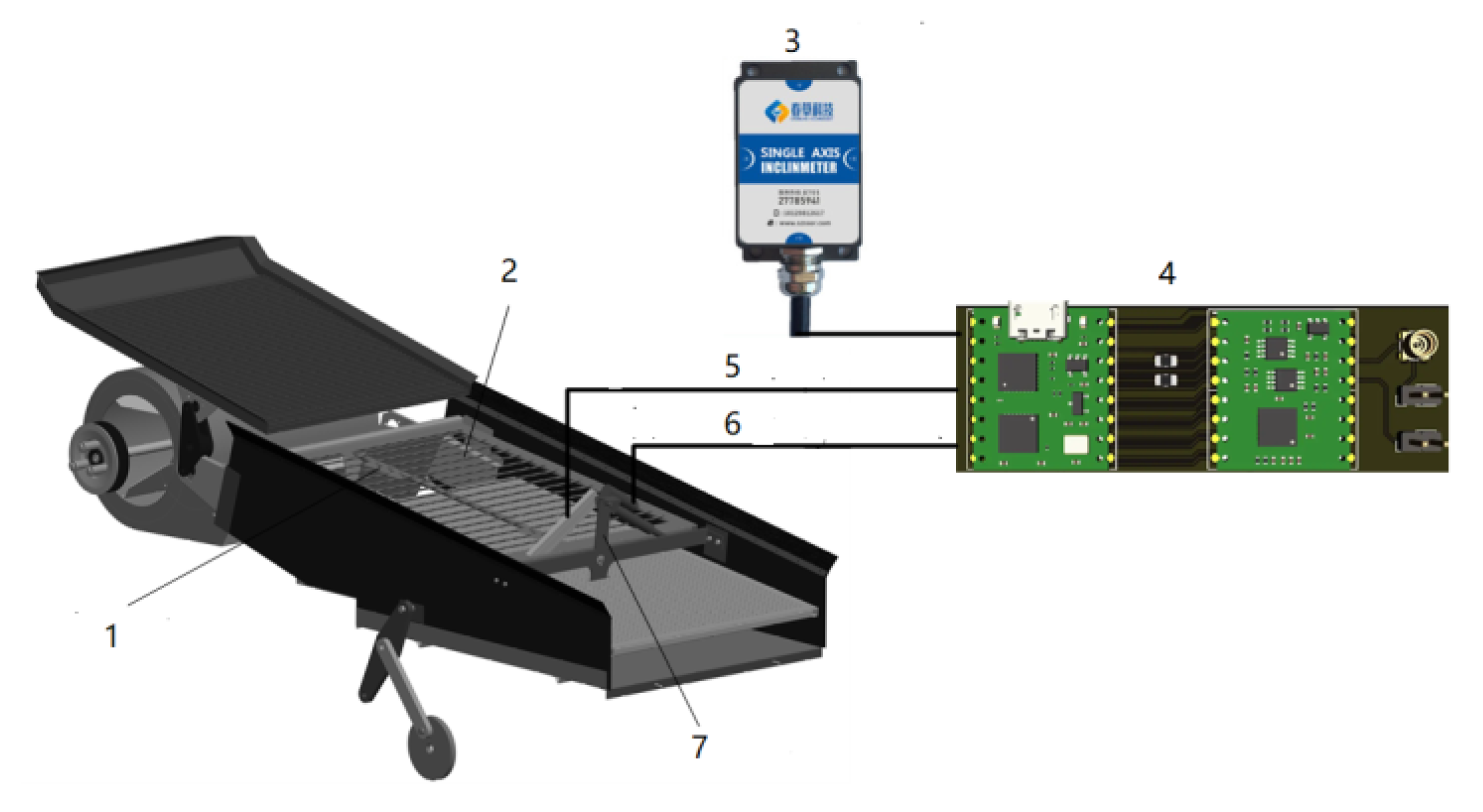
2.1. System Structure Composition
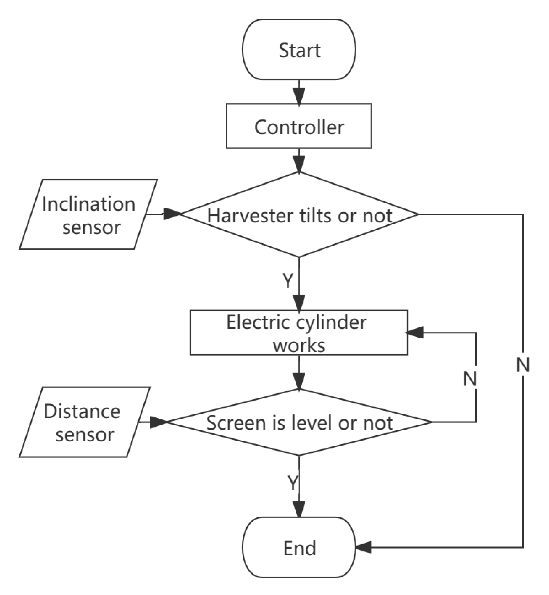
2.2. Working Principle
3. Design of the Automatic Leveling Control System
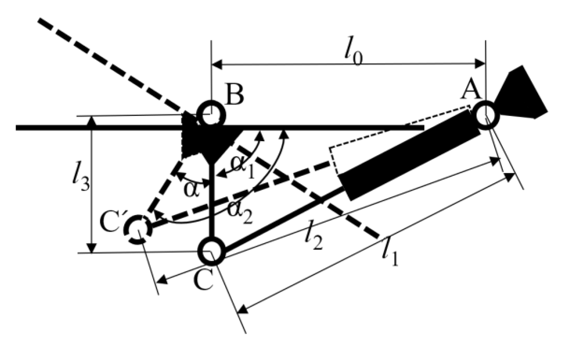
3.1. Leveling Mechanism Design
3.2. Dynamic Equation of the Leveling Mechanism
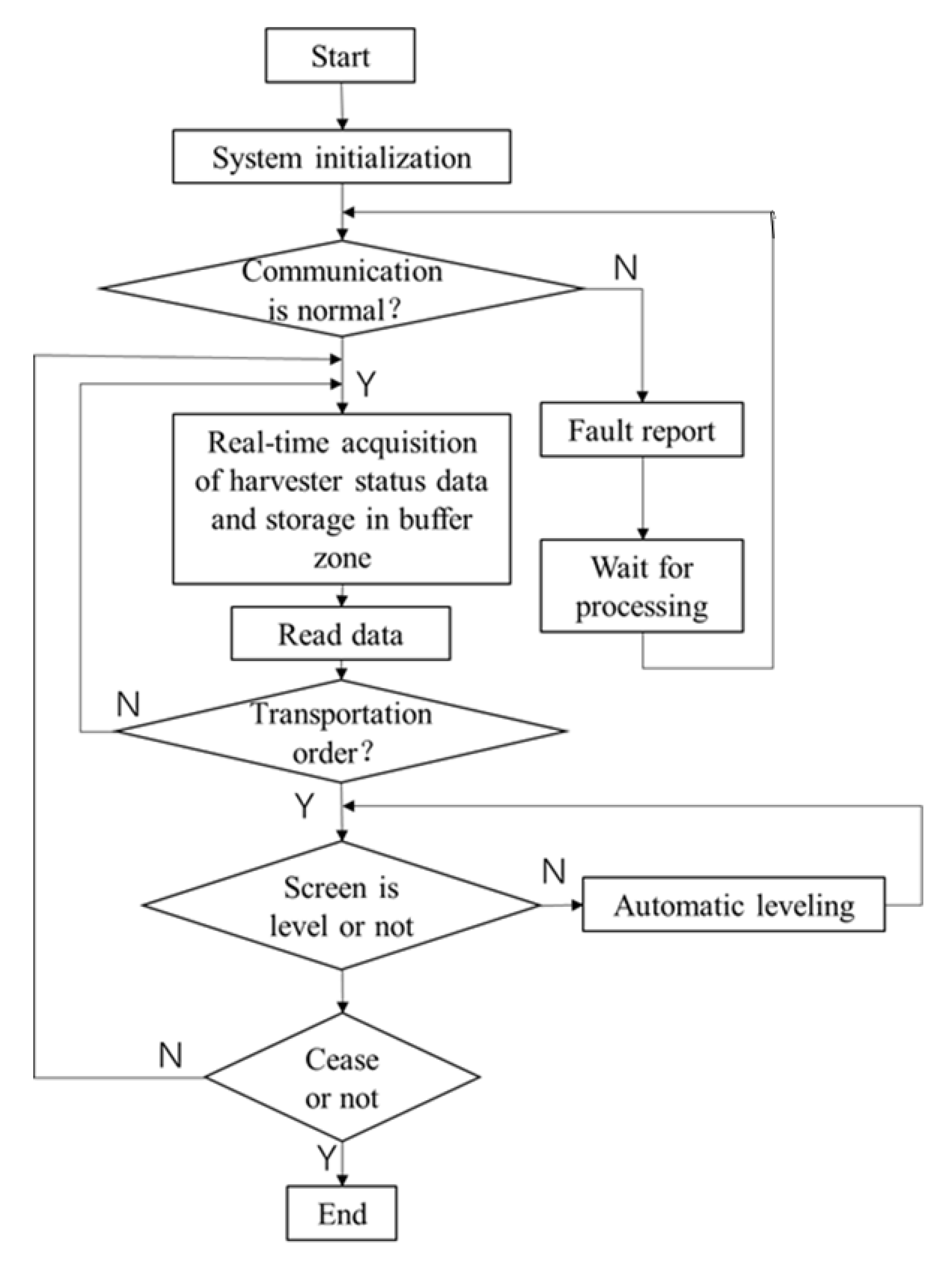
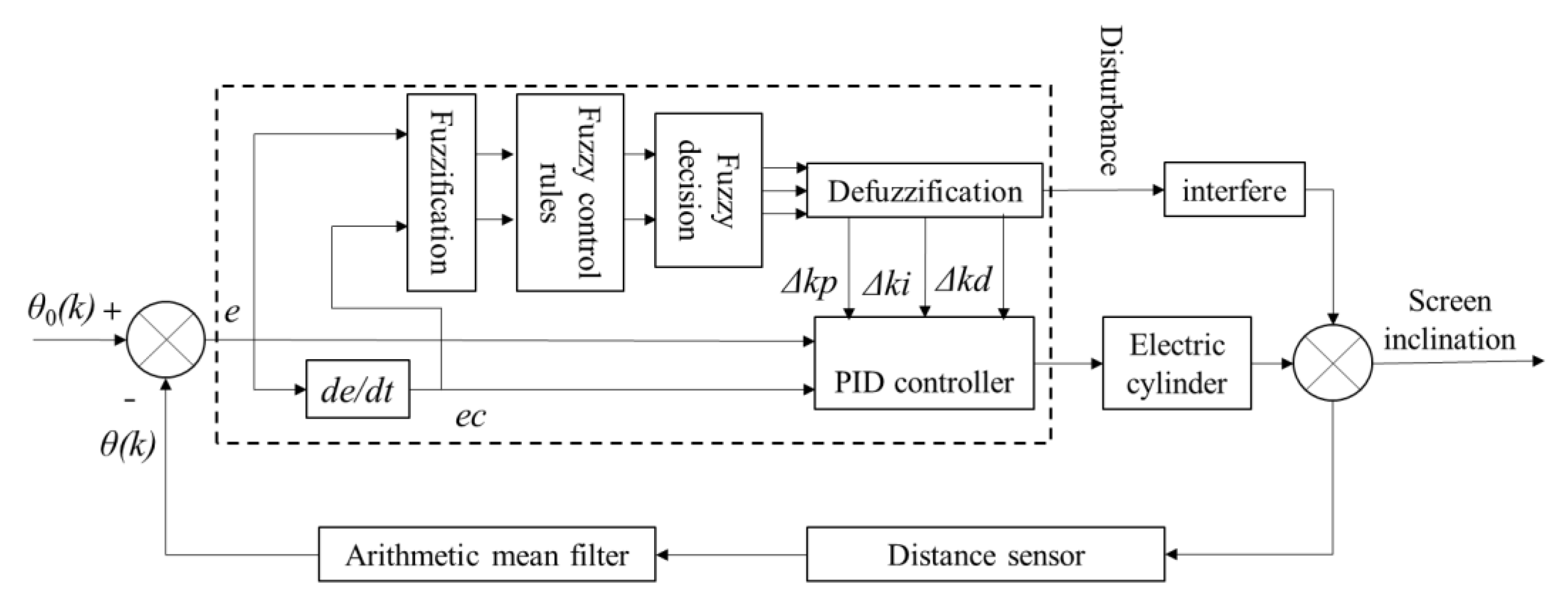
3.3. Control System Design
3.3.1. Hardware Design
3.3.2. Software Design
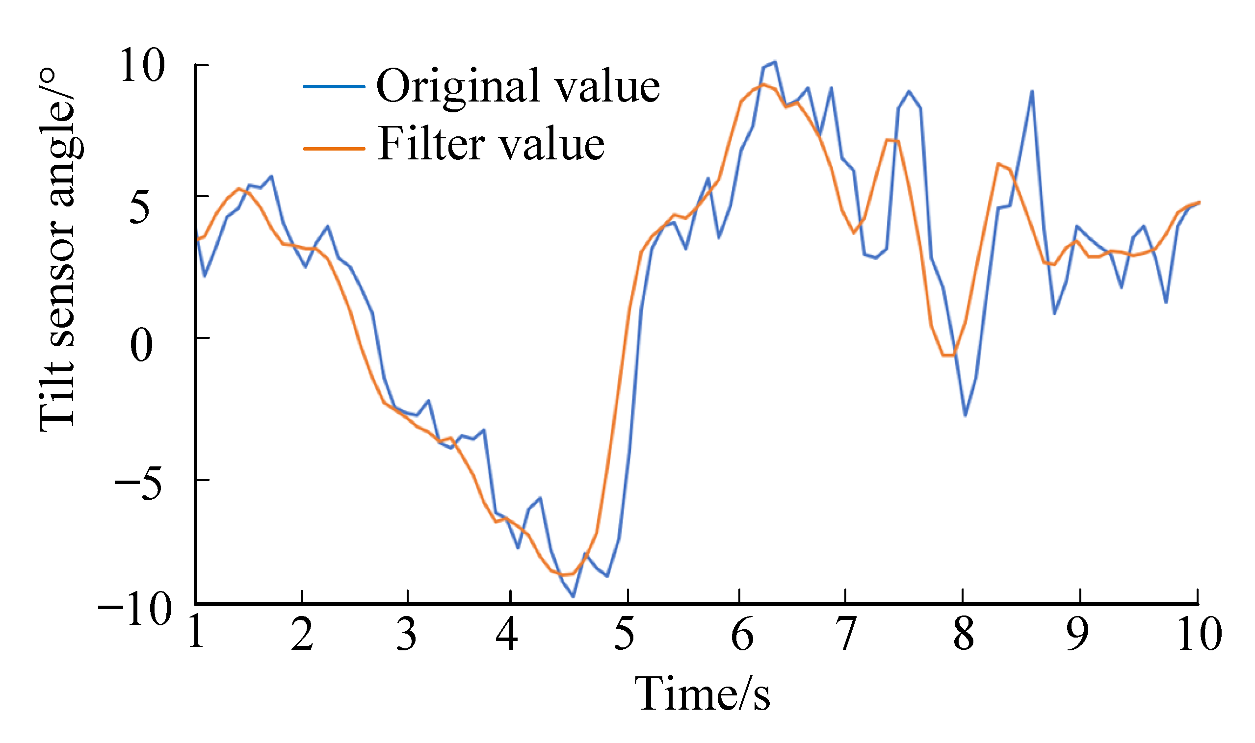
3.3.3. Filter Design
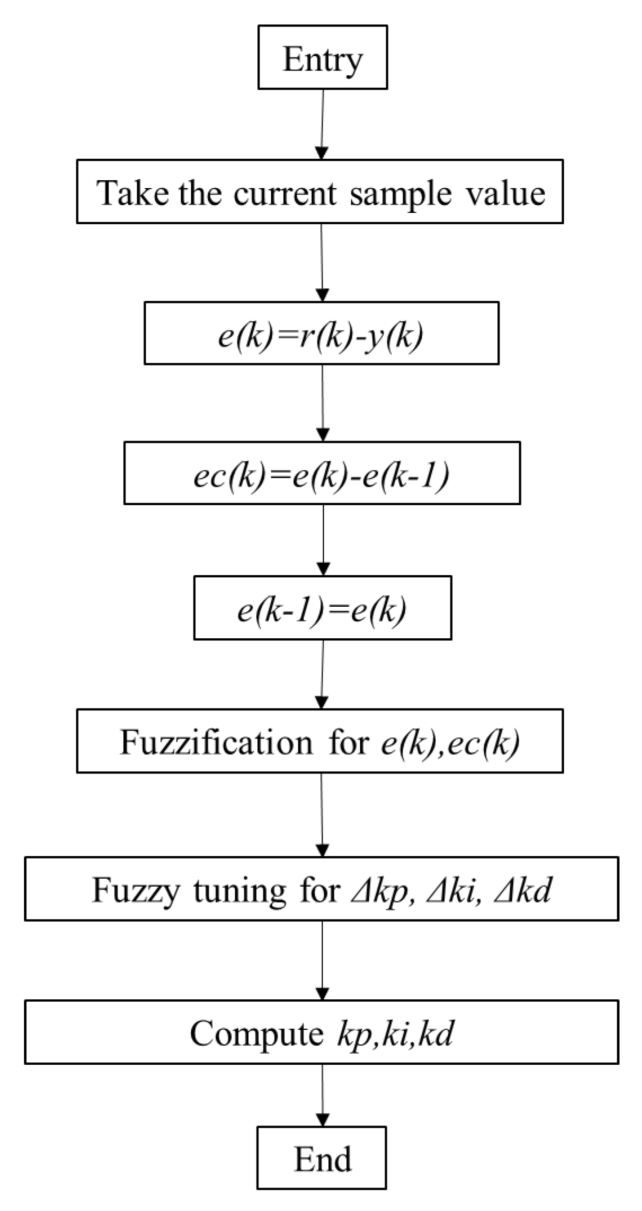
3.4. Control Algorithm
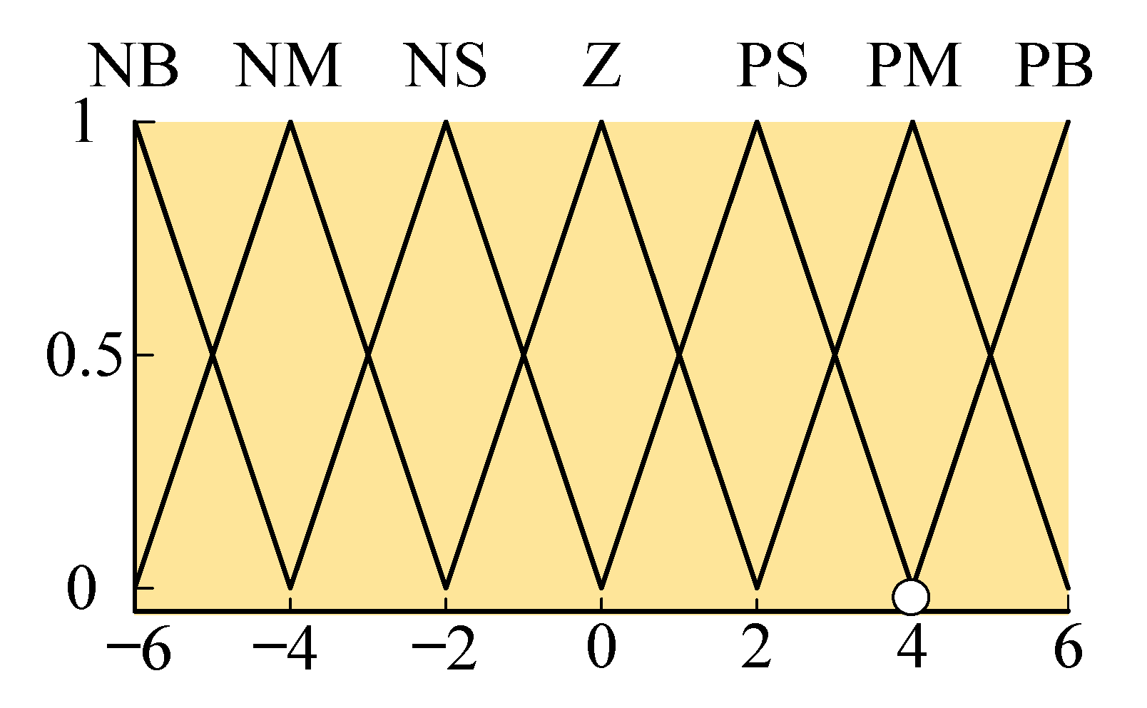
Fuzzy PID Control Algorithm
- (1)
- When e is large, to quickly correct the deviation, the larger Kp and the smaller Ki and Kd should be selected to avoid a large overshoot of the system;
- (2)
- When e and ec are medium, the smaller Kp should be selected to avoid a large overshoot. At the same time, because the value of Kd will have a greater impact on the control effect of the system, the smaller Kp should be selected to locate Ki and Kd at a suitable position;
- (3)
- When e is small, to ensure the better and more stable performance of the system, Kp and Ki should both be larger. At the same time, to avoid oscillation of the system at the set value, and considering the anti-interference performance of the system, when ec is large, Kd can be smaller, and when ec is small, Kd can be larger. Generally, Kd is of medium size. The relationship between the PID regulating parameters and the system time domain performance indicators is shown in Table 2.
4. Tests
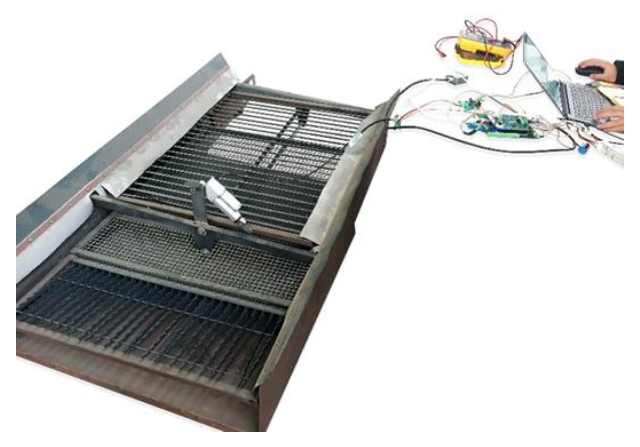
4.1. System Test
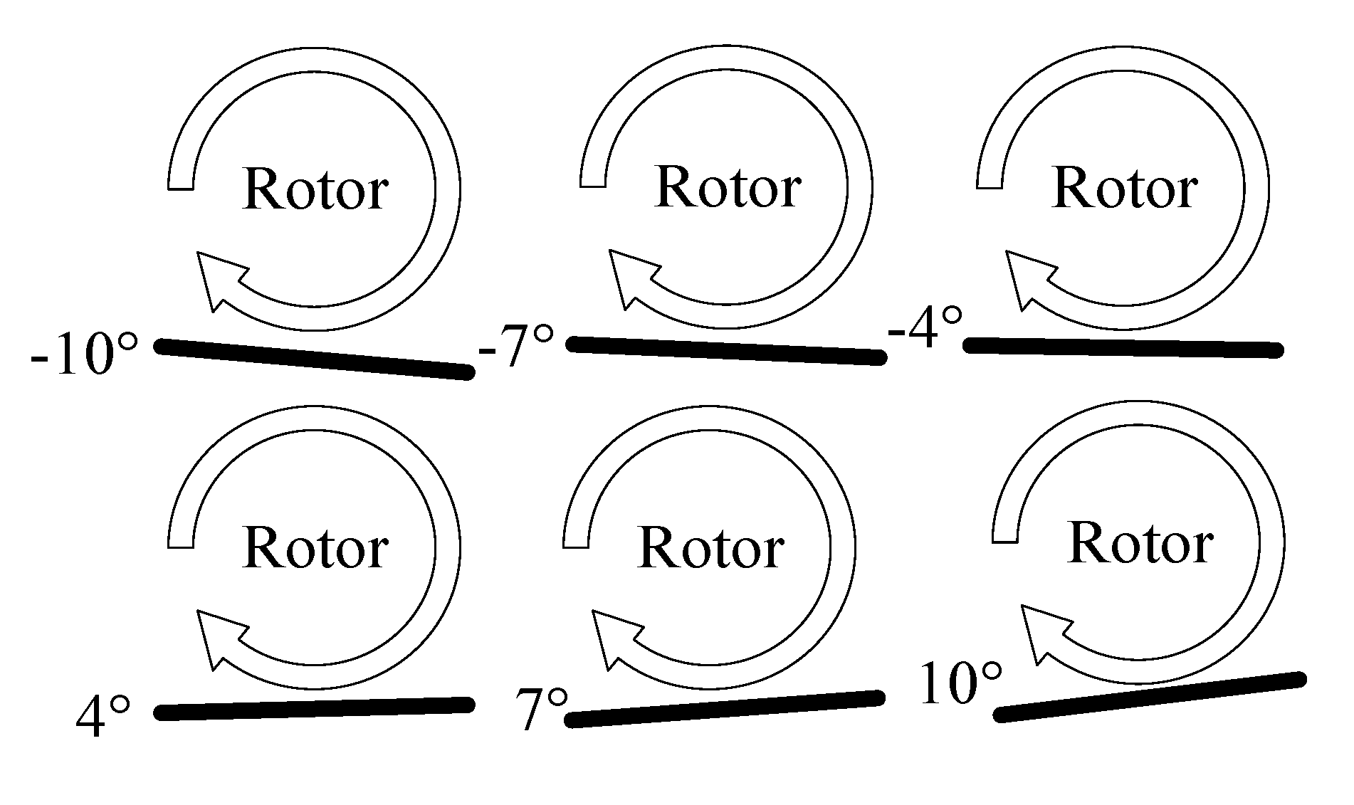
4.2. System Leveling Response Test
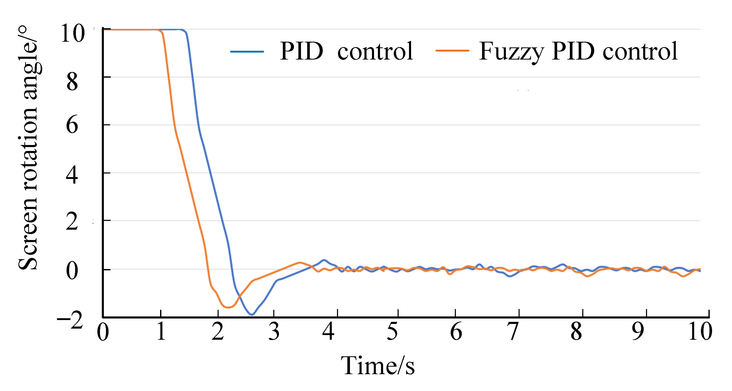
4.3. Static Contrast Test
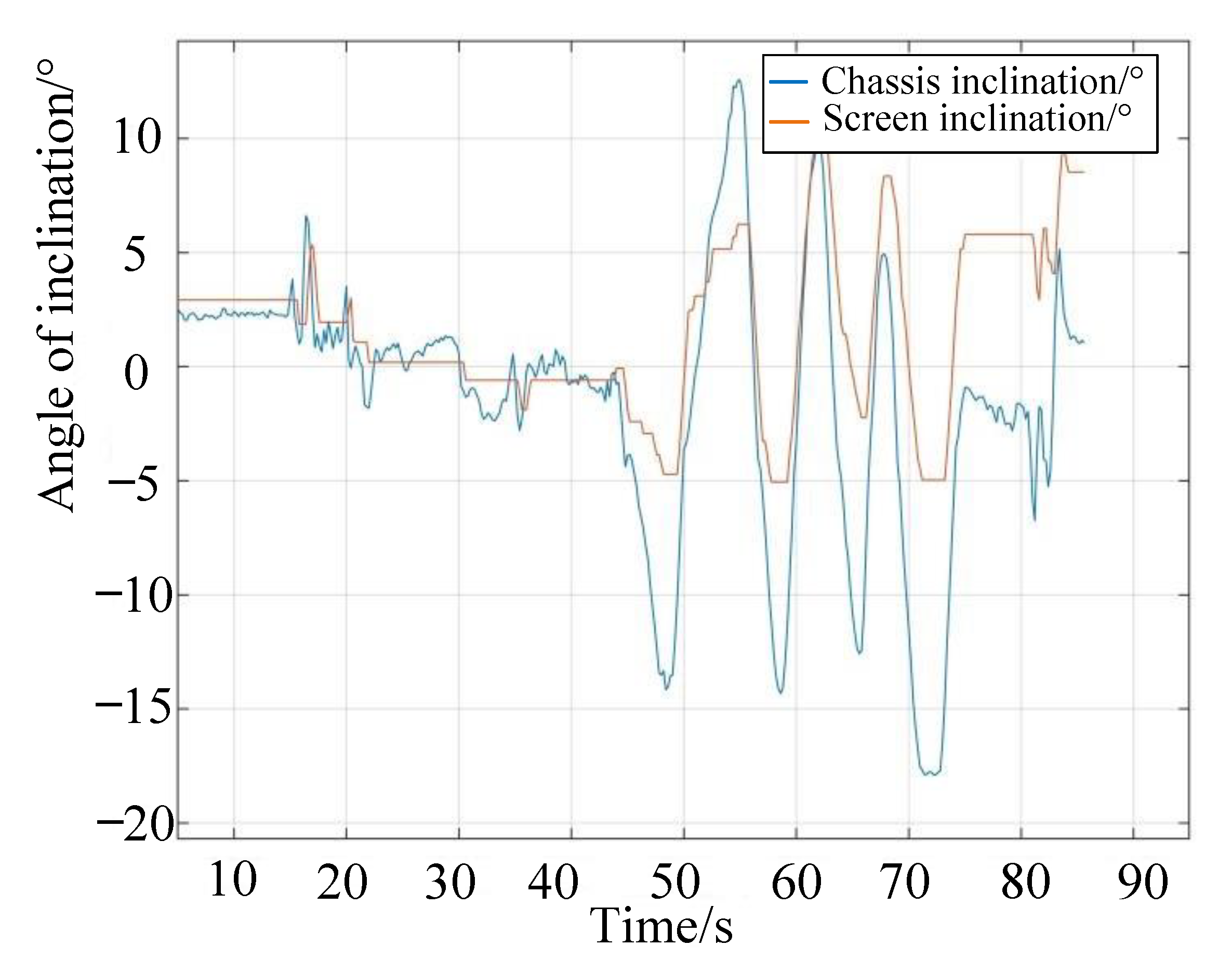
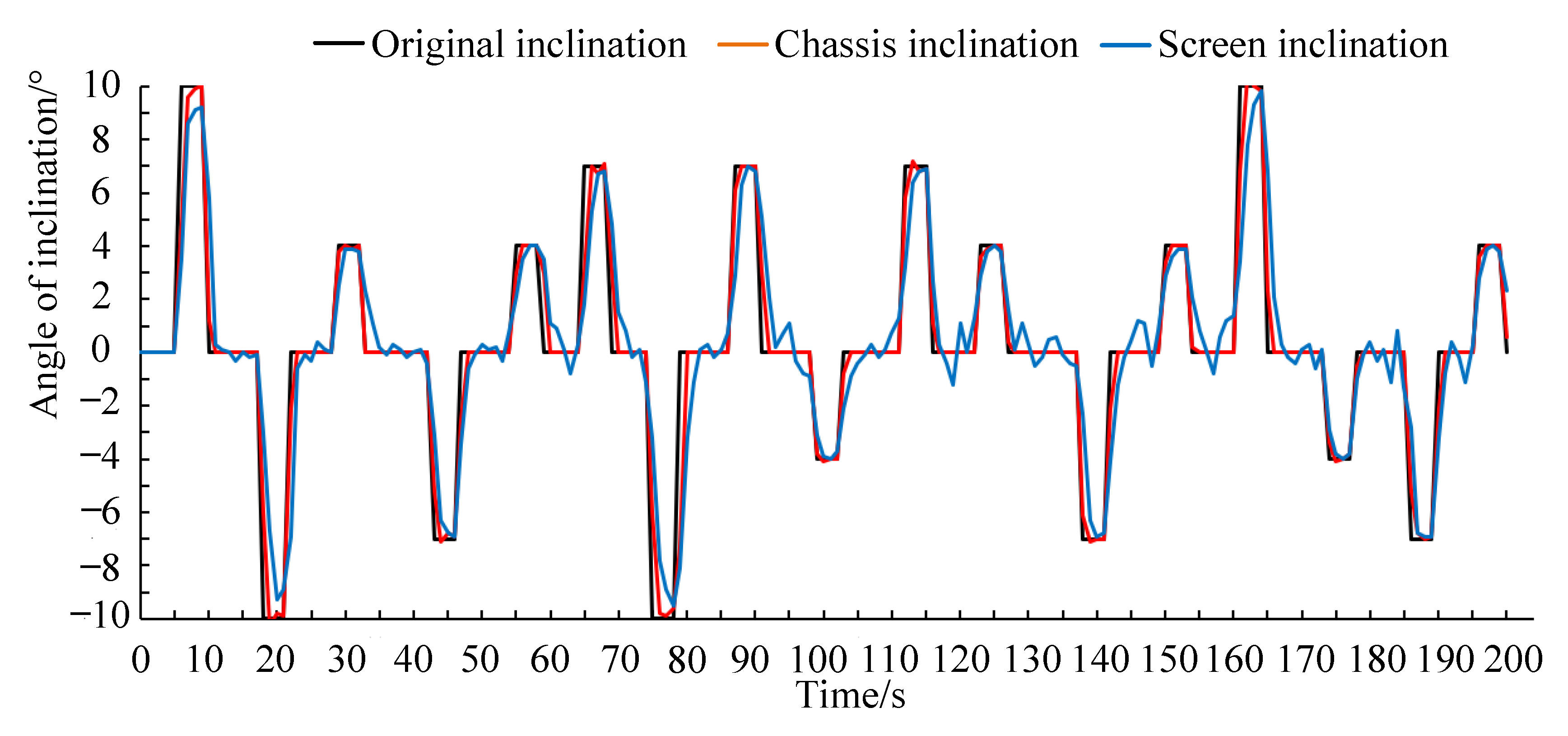
4.4. Field Validation Test
5. Conclusions
Author Contributions
Funding
Institutional Review Board Statement
Informed Consent Statement
Data Availability Statement
Conflicts of Interest
References
- Li, D.; Lu, W.; Wang, X. Research status and development trend of cyclone separating cleaning unit of combine harvesters. Agric. Equip. Veh. Eng. 2016, 54, 8–13. [Google Scholar]
- Xu, L.; Li, Y.; Li, Y. Research progress on cleaning technology and device of grain combine harvester. Trans. Chin. Soc. Agric. Mach. 2019, 50, 1–16. [Google Scholar]
- Hou, J.; Xie, F.; Liu, D. Research progress on air-and-screen cleaning device for combined harvester. Agric. Eng. Equip. 2020, 47, 12–17. [Google Scholar]
- Xiong, W.; Li, Y.; Liu, J. Design and experiment of threshing and cleaning device for hilly rice and rape combine harvester. J. Agric. Mech. Res. 2022, 44, 167–171. [Google Scholar]
- Chen, Z.; Gao, L.; Chen, C. Analysis on technology status and development of peanut harvest mechanization of china and the united states. Trans. Chin. Soc. Agric. Mach. 2017, 48, 1–21. [Google Scholar]
- Wellington, C.K.; Bruns, A.J.; Sierra, V.S.; Phelan, J.J.; Hageman, J.M.; Dima, C.; Boesch, H.; Herman, H.; Pezzementi, Z.A.; Male, C.R.; et al. Grain Quality Monitoring. U.S. Patent 9779330, 26 December 2014. [Google Scholar]
- Li, J.; Zhao, D.; Shen, H. Research on screening effect of grain three dimensional parallel vibrating screen based on DEM. China Mech. Eng. 2013, 24, 1018–1022. [Google Scholar]
- Wang, C.; Li, Y.; Ma, L. Design of three degree of freedom hybrid vibration screen. Trans. Chin. Soc. Agric. Mach. 2011, 42, 69–73. [Google Scholar]
- Li, H.; Li, Y.; Tang, Z. Test study on cleaning performance of air and screen cleaning mechanism. Chin. Agric. Mech. 2010, 6, 54–57. [Google Scholar]
- Shen, D.; Li, B.; Sun, L. Shuangfengdao qingxuan zhuangzhi zai guwu lianhe shouhuoji shang yingyong [Application of double air duct cleaning device on grain combine harvester]. Nongye Jixie Xuebao 1995, 4, 151–155. [Google Scholar]
- Xu, L.; Yu, L.; Li, Y. Numerical simulation of internal flow field in centrifugal fan with double outlet and multi-duct. Trans. Chin. Soc. Agric. Mach. 2014, 45, 78–86. [Google Scholar]
- Liang, Z.; Li, Y.; Mam, P. Structure optimization and experiment on cleaning system in longitudinal-axial combine harvester. J. Agric. Mech. Res. 2018, 40, 70–174. [Google Scholar]
- Liang, Z.; Li, Y.; Zhao, Z. Monitoring mathematical model of grain cleaning losses on longitudinal-axial flow combine harvester. Trans. Chin. Soc. Agric. Mach. 2015, 46, 106–111. [Google Scholar]
- Yuan, J.; Yang, J.; Wan, X. Design and experiment of cylinder sieve type re-cleaning device for rape combine harvester. Trans. Chin. Soc. Agric. Mach. 2022, 53, 99–108. [Google Scholar]
- Wang, C.; Li, Y.; Ma, L. Design of multi-dimensional vibration screening test bench based on parallel mechanism. Trans. Chin. Soc. Agric. Mach. 2012, 43, 70–74. [Google Scholar]
- Li, Y.; Liu, X.; Ma, Z. Investigation on three-dimensional parallel screening performance based on initial phase of different branches. Trans. Chin. Soc. Agric. Mach. 2017, 48, 88–95. [Google Scholar]
- Dai, F.; Fu, Q.; Zhao, W. Design and test of double duct system of air-screen separating and cleaning machine for flax threshing material. Trans. Chin. Soc. Agric. Mach. 2021, 52, 117–125. [Google Scholar]
- Xu, L.; Li, Y.; Zhang, L. Development on test-bed of axial threshing and cleaning unit. Trans. Chin. Soc. Agric. Mach. 2007, 12, 85–88. [Google Scholar]
- Chen, X.; Wu, C.; Zhang, M. Development status and trend analysis of rapeseed combine harvester in China. J. Chin. Agric. Mech. 2018, 39, 28–31. [Google Scholar]
- Wei, L.; Che, Y.; Wang, F. Design and experiment of the ground profiling control system of combine header. J. Agric. Mech. Res. 2017, 39, 150–154. [Google Scholar]
- Chen, J.; Lian, Y.; Li, Y. Real-time grain impurity sensing for rice combine harvesters using image processing and decision tree algorithm. Comput. Electron. Agric. 2020, 175, 194–199. [Google Scholar] [CrossRef]
- Kowbel, W.; Xia, X.; Champion, W. PZT/polymer flexible composites for embedded actuator and sensor application. Proc. SPIE 1999, 3675, 32–34. [Google Scholar]
- Gorial, B.; Callaghan, J. Separation of Grain Straw in a Vertical Air Stream. J. Agric. Eng. Res. 1991, 48, 111–122. [Google Scholar] [CrossRef]
- Li, J.; Zeng, Q.; Deng, J. Screening process analysis for multi-dimensional parallel vibrating screen and optimization of screen surface movement. Trans. Chin. Soc. Agric. Mach. 2016, 47, 399–407. [Google Scholar]
- Chen, Q.; Han, Z.; Cui, J. Development status and trend current situation of self-propelled combine harvester. J. Agric. Sci. Technol. 2015, 17, 109–114. [Google Scholar]
- Li, Q.; Song, Y.; Yao, C. Intelligent design and optimization system for cleaning device of rice and wheat combine harvester. Trans. Chin. Soc. Agric. Mach. 2021, 52, 92–101. [Google Scholar]


| Parameter Name | Language Variable | Basic Universe | Quantization Factor |
|---|---|---|---|
| E(k) | E | (−1.2, 1.2) | Ke = 5 |
| ec(k) | Ec | (−1, 1) | Kec = 6 |
| Δkp(k) | Kp | (−1, 1) | KΔkp = 6 |
| Δki(k) | Ki | (−0.08, 0.08) | KΔki = 75 |
| Δkd(k) | Kd | (−0.1, 0.1) | KΔkd = 60 |
| Parameter Name | Parameter Change | Rise Time | Overshoot | Transition Time | Static Error |
|---|---|---|---|---|---|
| Kp | Enlarge | Reduce | Enlarge | Minor changes | Reduce |
| Ki | Enlarge | Reduce | Enlarge | Enlarge | Eliminate |
| Kd | Enlarge | Minor changes | Reduce | Reduce | Minor changes |
| EC | |||||||
| E | PB | PM | PS | Z | NS | NM | NB |
| PB | NB | NB | NM | NM | NM | Z | Z |
| PM | NB | NM | NM | NM | PS | Z | PS |
| PS | NM | NM | NS | NS | Z | PS | PS |
| Z | NM | NM | NS | Z | PS | PM | PM |
| NS | NS | NS | Z | PS | PM | PM | PM |
| NM | NS | Z | PS | PS | PM | PB | PB |
| NB | Z | Z | PS | PM | PM | PB | PB |
| EC | |||||||
| E | PB | PM | PS | Z | NS | NM | NB |
| PB | PB | PB | PM | PM | PS | Z | Z |
| PM | PB | PB | PM | PS | PS | Z | Z |
| PS | PB | PM | PS | PS | Z | NS | NM |
| Z | PM | PM | PS | Z | NS | NM | NM |
| NS | PS | PS | Z | NS | NS | NM | NB |
| NM | Z | Z | NS | NS | NM | NB | NB |
| NB | Z | Z | NS | NM | NM | NB | NB |
| EC | |||||||
| E | PB | PM | PS | Z | NS | NM | NB |
| PB | PB | PS | PS | PM | PM | PM | PB |
| PM | PB | PS | PS | PS | PS | Z | PB |
| PS | Z | Z | Z | Z | Z | Z | Z |
| Z | Z | NS | NS | NS | NS | NS | Z |
| NS | Z | NS | NS | NM | NM | NS | Z |
| NM | Z | NS | NM | NM | NB | NS | PS |
| NB | PS | NM | NB | NB | NB | NS | PS |
| Inclination/° | Inclination of Screen after Leveling/° | Leveling Time/s | Average Error/° | Root-Mean-Square Error/° | Average of Leveling Time/s |
|---|---|---|---|---|---|
| −10 | −0.59 | 1.54 | −0.62 | 0.024 | 1.49 |
| −0.60 | 1.48 | ||||
| −0.62 | 1.44 | ||||
| −0.63 | 1.51 | ||||
| −0.65 | 1.47 | ||||
| −7 | −0.51 | 1.12 | −0.52 | 0.012 | 1.13 |
| −0.54 | 1.11 | ||||
| −0.52 | 1.15 | ||||
| −0.51 | 1.15 | ||||
| −0.52 | 1.14 | ||||
| −4 | −0.37 | 0.82 | −0.34 | 0.032 | 0.81 |
| −0.36 | 0.78 | ||||
| −0.29 | 0.79 | ||||
| −0.35 | 0.84 | ||||
| −0.35 | 0.81 | ||||
| 4 | 0.33 | 1.16 | 0.34 | 0.034 | 1.13 |
| 0.29 | 1.17 | ||||
| 0.38 | 1.10 | ||||
| 0.35 | 1.11 | ||||
| 0.36 | 1.11 | ||||
| 7 | 0.52 | 1.42 | 0.51 | 0.009 | 1.43 |
| 0.51 | 1.34 | ||||
| 0.50 | 1.41 | ||||
| 0.51 | 1.51 | ||||
| 0.52 | 1.46 | ||||
| 10 | 0.59 | 1.88 | 0.61 | 0.021 | 1.85 |
| 0.62 | 1.86 | ||||
| 0.61 | 1.82 | ||||
| 0.64 | 1.85 | ||||
| 0.59 | 1.84 |
| Inclination/° | Test 1/% | Test 2/% | Test 3/% | Average/% | Standard Deviation/% |
|---|---|---|---|---|---|
| −10 | 6.79 | 6.68 | 6.93 | 6.80 | 0.125 |
| −7 | 5.26 | 5.27 | 4.92 | 5.15 | 0.199 |
| −4 | 3.49 | 3.68 | 3.24 | 3.47 | 0.221 |
| 0 | 2.95 | 3.12 | 2.96 | 3.01 | 0.095 |
| 4 | 3.37 | 3.13 | 3.34 | 3.28 | 0.131 |
| 7 | 4.34 | 4.40 | 4.52 | 4.42 | 0.092 |
| 10 | 5.75 | 5.82 | 5.80 | 5.79 | 0.036 |
| Inclination/° | Test 1/% | Test 2/% | Test 3/% | Average/% | Standard Deviation/% |
|---|---|---|---|---|---|
| −10 | 3.04 | 2.87 | 3.03 | 2.98 | 0.095 |
| −7 | 3.00 | 2.97 | 2.97 | 2.98 | 0.017 |
| −4 | 3.00 | 2.96 | 2.89 | 2.95 | 0.056 |
| 0 | 2.88 | 2.91 | 2.97 | 2.92 | 0.046 |
| 4 | 3.04 | 2.99 | 2.76 | 2.93 | 0.149 |
| 7 | 2.94 | 2.87 | 2.83 | 2.88 | 0.056 |
| 10 | 2.79 | 2.90 | 2.74 | 2.81 | 0.082 |
Disclaimer/Publisher’s Note: The statements, opinions and data contained in all publications are solely those of the individual author(s) and contributor(s) and not of MDPI and/or the editor(s). MDPI and/or the editor(s) disclaim responsibility for any injury to people or property resulting from any ideas, methods, instructions or products referred to in the content. |
© 2023 by the authors. Licensee MDPI, Basel, Switzerland. This article is an open access article distributed under the terms and conditions of the Creative Commons Attribution (CC BY) license (https://creativecommons.org/licenses/by/4.0/).
Share and Cite
Wu, J.; Tang, Q.; Mu, S.; Yang, X.; Jiang, L.; Hu, Z. Design and Test of Self-Leveling System for Cleaning Screen of Grain Combine Harvester. Agriculture 2023, 13, 377. https://doi.org/10.3390/agriculture13020377
Wu J, Tang Q, Mu S, Yang X, Jiang L, Hu Z. Design and Test of Self-Leveling System for Cleaning Screen of Grain Combine Harvester. Agriculture. 2023; 13(2):377. https://doi.org/10.3390/agriculture13020377
Chicago/Turabian StyleWu, Jun, Qing Tang, Senlin Mu, Xiaoxuan Yang, Lan Jiang, and Zhichao Hu. 2023. "Design and Test of Self-Leveling System for Cleaning Screen of Grain Combine Harvester" Agriculture 13, no. 2: 377. https://doi.org/10.3390/agriculture13020377