1. Introduction
With the rapid development of China’s society, the excessive use of chemical fertilizers leads to problems such as the decline in land quality, the decline in crop quality, and the increase in production costs caused by serious environmental pollution [
1,
2,
3]. The excessive use of chemical fertilizers is one of the important factors hindering sustainable development. In the long run, if chemical fertilizers are used without restraint, the land quality will decline sharply. In order to increase the per-667 m
2 yield, producers will rely more on the use of chemical fertilizers, which would create a vicious circle. Fertilizer plays an irreplaceable role in ensuring food security and promoting agricultural production, but excessive and unscientific application will lead to environmental pollution and other problems. Over the years, extensive use of single element fertilizers or single variety fertilizers has caused soil compaction [
4,
5], nitrate accumulation, and nutrients imbalance, hindering the normal growth and development of crops, and leading to crop yield reduction or even death [
6,
7,
8]. To solve these problems, since 2015, farmers have obtained support and guidance from the government to increase the application of organic fertilizer, among which green manure is one of the representatives of organic fertilizer. As one of the important crops of traditional agriculture in China, there are multiple functions for green manure such as improving soil, fertilizing fields, reducing water and soil loss, preventing pests and diseases, as well as improving crop yield. As a typical legume green manure, the planting area of hairy vetch is increasing year by year.
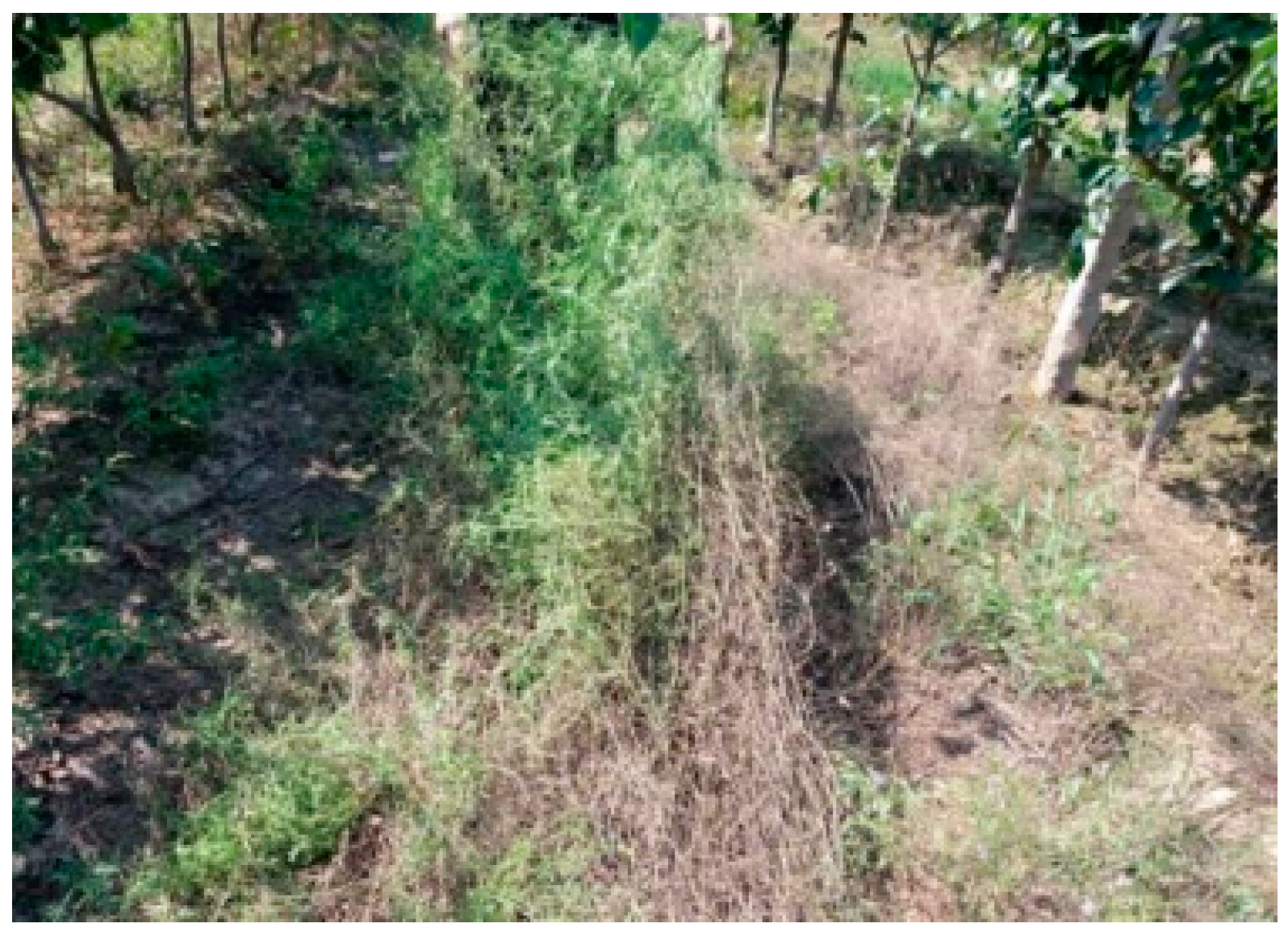
Hairy vetch is a long-stem crop belonging to the genus Vicia. It is an annual or perennial herb and widely used in covering, pressing for fertilizer, and forage utilization [
9,
10,
11]. It has the functions of improving soil and fertilizing fields, reducing water and soil loss, controlling pests and diseases, and improving crop yield [
12,
13,
14,
15,
16,
17], which is a natural green manure. In recent years, the planting area of hairy vetch had increased while the harvest mode was still mainly manual. This is due to the entanglements of stems between plants during the growth of hairy vetch, resulting in the inability of harvesting machinery to harvest effectively (
Figure 1).
For long-stem crops, such as hairy vetch, potato vine, and alfalfa, the stems or vine between plants are creeping and intertwining [
18,
19]. Kemper et al. proposed a new disc rotary mower, using two sets of cutters with the same direction and different speeds to cut alfalfa plants, reducing the cutting speed and improving the cutting quality [
20]. Kondratyev, V.N. et al. designed a cutter device to achieve the cutting effect on long-stem crops and reduce energy consumption [
21]. According to the characteristics of long stems and creeping growth, a sweet potato seedings and vines crushing and returning machine was arranged and studied to improve the working efficiency [
22]. To prevent the cutter from touching the ground when cutting prostrate long-stemmed crops, the coating of rotary cutters was enhanced to increase the blade life and productivity [
23]. The 9GC-203S hanging lawn mower in Koroney, Germany, and the GMD10&100 hanging lawn mower in Kuen, The electromechanical and hydraulic technology integration technology was adopted in France to realize the joint operation of more than four discs. Adjusting the overlapping width of adjacent oval cutter discs to improve kinetic energy and reduce the probability of twining and missing cutting of long-stem crops [
24,
25,
26,
27,
28]. At present, the harvesting machinery for long-stem crops has been integrated into hydraulic devices and control systems to achieve automatic and personalized harvesting. However, most of the existing long-stem crop are concentrated in large-scale cutting operations and the electromechanical hydraulic integration equipment is expensive, which is inconsistent with the planting mode of long-stem crops in China, resulting in a low crop harvesting efficiency, low crushing rate and ease of entanglement, and the promotion cost is too high.
Therefore, based on the analysis of the physical characteristics of hairy vetch, a feeding device is designed to cut and recover the creeping twined stems. The ROCKY discrete element software was used to simulate the working state of feeding device, and the orthogonal rotation combination simulation test was carried out to optimize its working parameters. Through the on-site performance test, the rationality of the design of the feeding device was verified. The feeding device can provide a reference for the design and optimization of the hairy vetch harvesting machinery, which is of great significance for the mechanization development and the promotion of products promotion of hairy vetch.
2. Analysis of Physical Properties of Hairy Vetch Stem
2.1. Stem Characteristics
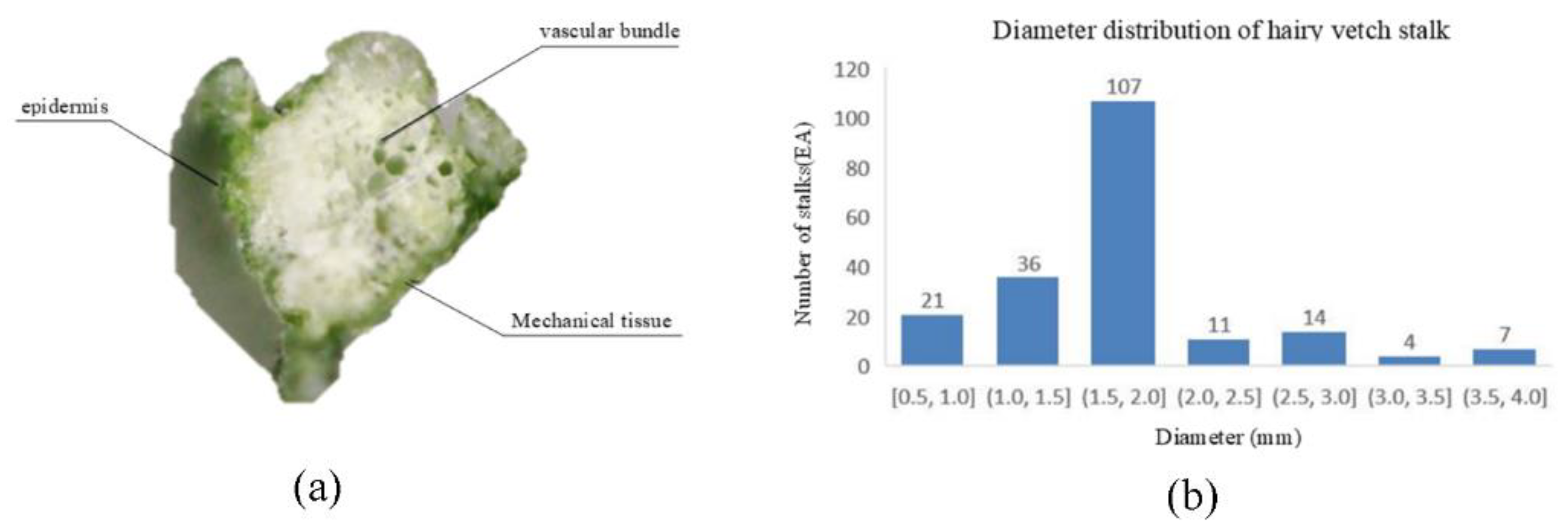
The stem of hairy vetch is a quadrangular structure with many branches on the nodes, the cross section (
Figure 2a) of the stem is epidermis, mechanical tissue and vascular bundle from outside to inside. The length of its stem is slender and soft, up to 1–3 m, with a natural height of 40–60 cm when mature. Two hundred hairy vetch stems diameters were measured at random, and the diameter distribution was obtained (
Figure 2b). The number of stems with diameters between 1.5 mm to 2.0 mm were the largest, accounting for 53.5% of the total number of samples. Therefore, stems with diameter in this range were selected for testing.
2.2. Mechanical Properties of Hairy Vetch Stem
2.2.1. Test Method
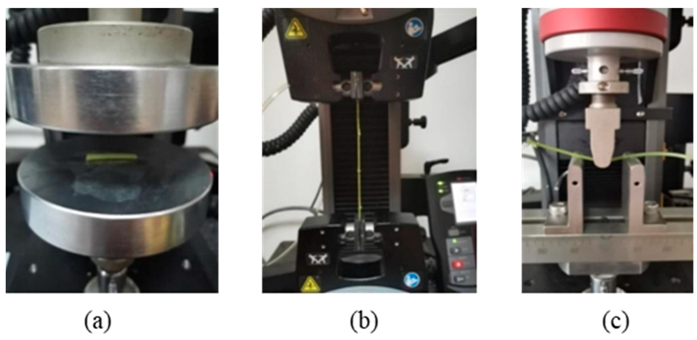
The physical properties and mechanical properties of hairy vetch stem were studied. A total of 100 samples with a length of 500 mm (moisture content of 60~70%) were prepared, and 10 samples were taken as a group for testing. During the experiment, the samples were put into sealed bags and stored in a refrigerated cabinet with a constant temperature of 4 °C. The samples were taken whenever they were used. The temperature in the test environment shall be kept between 20 °C and 25 °C, and other conditions shall be as consistent as possible with the actual harvest environment. For the radial compression test, 20 mm-long stem was taken from the sample as the test object, and 5 N preload and a compression speed of 5 mm/min were applied to them until the samples were broken and snapped off (
Figure 3a). In the same way, a 200 mm-long stem was taken from the sample as the test object, a radial compression test was conducted, and 10 N preload and a tensile speed of 10 mm/min were applied to it until the sample was broken (
Figure 3b). For radial bending test, a 120 mm-long stem cut from the sample as the test object, symmetrically placed on the clamp with a span of 40 mm, 0.2 N preload and 10 mm/min shear speed were applied (
Figure 3c) to it until the sample is cut. After removing the abnormal sample data according to each group of data, calculate the average value to ensure that the error between the measured data and the actual data is small. (The test sample data described in this article are obtained after averaging 10 groups of data.)
2.2.2. Test Results and Analysis
As shown in
Figure 4a,b, it can be seen that the internal tissues of hairy vetch stalks are damaged during compression, and the skin gradually breaks with the increase in load, leading to the destruction of stalks and loss of compression resistance.
The radial compressive strength of hairy vetch stems is expressed by the ratio of the critical pressure to the cross-sectional area, namely:
where:
—Compressive strength of the ith sample, MPa;
—Critical pressure of the ith sample, N;
—The calibration length of the ith sample, mm;
—Diameter of the ith specimen, mm.
The critical pressure, compressive strength and elastic modulus of hairy vetch stalk are shown in
Table 1.
- 2.
Analysis on the results of axial tensile test of hairy vetch stalk
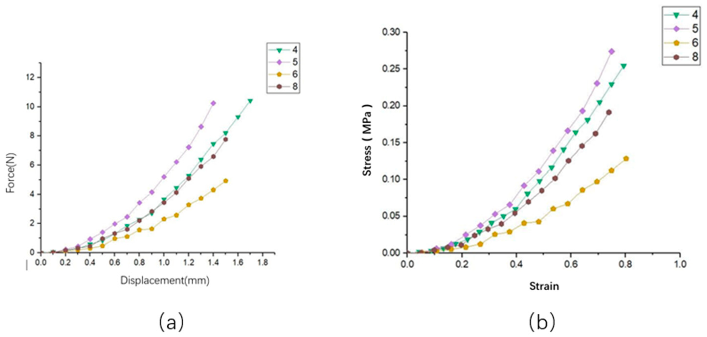
As shown in
Figure 5a,b, the hairy vetch stalk reaches the failure limit with the increasing tensile load. It can be seen from the curve that the tensile strength and load at the same position of different hairy vetch plants vary unevenly, which is caused by different physiological characteristics such as diameter of different hairy vetch plants.
The axial tensile strength of hairy vetch stems is expressed by the ratio of tensile load and cross-sectional area, namely:
where:
Pi—Tensile strength of the ith stem diameter, MPa;
Fi—The breaking force of the ith stalk, N;
ri—Diameter of the ith stalk, mm.
The breaking load, tensile strength and elastic modulus of hairy vetch stalks are shown in
Table 1.
- 3.
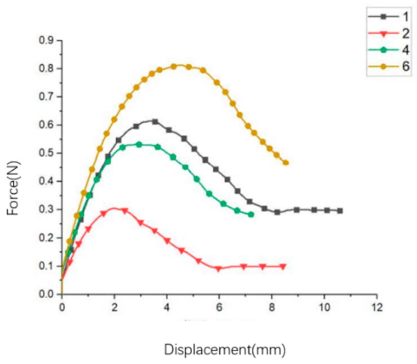
Analysis on the results of radial bending test of hairy vetch stalk
As shown in
Figure 6, the radial bending load displacement curve of hairy vetch stalk shows that the displacement load curve is linear at the initial stage of bending, the bending deflection increases according to the increase in load. When the hairy vetch stalk reaches the bending yield limit, the stalk will yield under the load for a period of time, and the displacement load curve will fluctuate slightly. With the increase in the displacement of the indenter, the stem breaks due to the stem being composed of fibers, etc., and the fracture is incomplete. At this time, the breaking load of the sample slowly decreases until the end of the test.
Bending strength of hairy vetch stalk
where:
Mmax—The maximum bending moment of the hairy vetch sample during bending;
Wz—Bending section modulus of hairy vetch stalk
The bending elastic modulus E of hairy vetch stalk can be calculated by the following formula:
where:
F—bending load of stem, N;
L—gauge distance of three fulcrums, mm;
Y—bending deflection of the midpoint of the sample, mm;
The bending load, bending strength and bending shear modulus of hairy vetch stalks measured in the test are shown in
Table 1.
3. Design of the Feeding Device of the Hairy Vetch Harvester
3.1. Structure and Working Principles of the Device
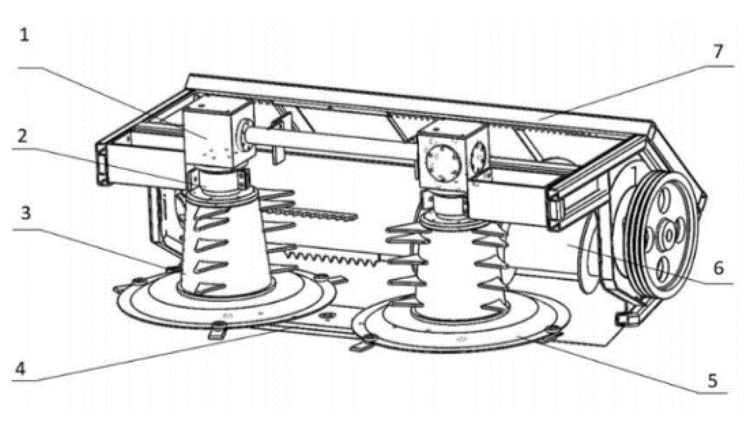
The feeding device of the hairy vetch harvester (
Figure 7) were mainly composed of cutting device, vertical drum, spiral conveyor and a power transmission system, which, respectively, realizes the functions of cutting the stem, pulling the stems inward, conveying and gathering stems, as well as power distribution. During operation, the power was transmitted by the engine to the bevel gear transmission case through the universal joint coupling. The bevel gear transmission case transmitted power to the vertical drum and cutter. Then, the stem was cut by the cutter and transported upward to the spiral conveyor by the vertical drum. The stems were gathered by the spiral conveyor and finally pulled out by the paddles.
3.2. Design of Key Components
3.2.1. Design of Cutting Device
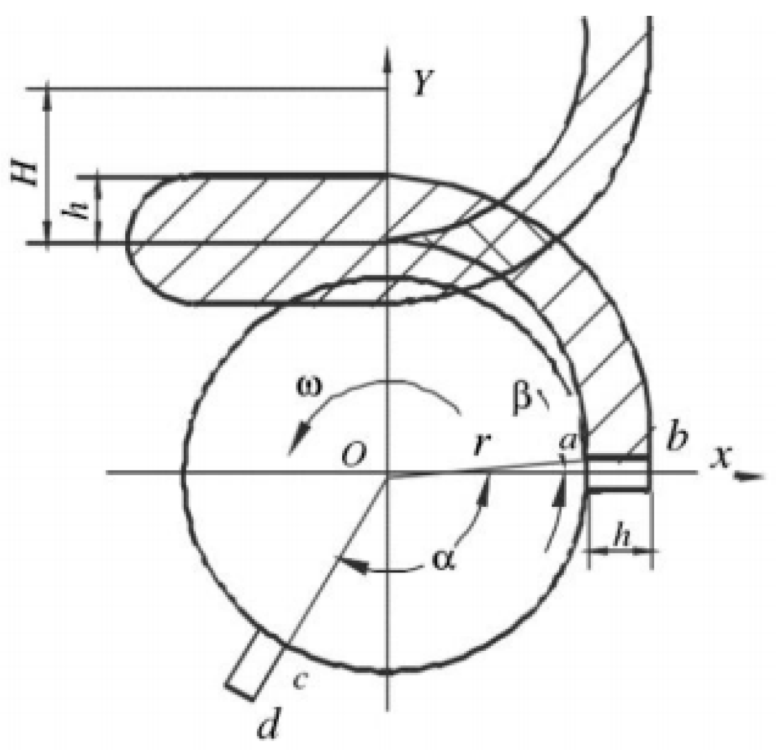
In view of the problem that the land is not centralized and the land is small in China, the double-disc rotary cutter was selected [
29]. The cutter of the disc cutter moves in a circle around the center of the cutter head. The motion track of the cutter was a cycloid (
Figure 8), and the area of its edge line sweeping the ground was a cycloid belt, and its bandwidth was similar to the length of the edge when the machine was in uniform linear motion.
The cutting speed at different positions of the cutter was different. The root (point a) speed of the cutter was the minimum and the tip (point b) speed was the maximum. According to the fact that the hairy vetch stem can be effectively cut when the cutting speed reaches 40 m/s, the cutter speed and the minimum speed should be calculated based on the root.
When the rotation and movement direction of the root part of the cutter a is opposite to the forward direction of the machine, the linear velocity of the cutter is minimized when:
and:
where:
is the cutting speed, in m/s;
R is the radius of the inner end of the blade, in m;
is the angular velocity of circular motion, ω = 2πn, in rad/s;
θ is the angle of the connecting line between the inside and outside end points of the blade and the cutter head;
is the advance speed of the machine, in m/s;
is the minimum linear speed of cutter, in m/s.
The optional range of forward speed of full feed self-propelled combine harvester is 4–10 km/h [
25], so 9 km/h (2.5 m/s) was selected for calculation. Compared with the cutter head of forage machinery [
26], the larger cutter head diameter was selected to prevent the long stem from winding on the cutter head. The diameter was defined as 707 mm, the circumference was 2220 mm, and the cut length of the cut stem was 0.3–1.1 m. Let
, and it was obtained that
where:
n is cutter speed, in r/s;
is minimum cutting speed of cutter, in 40 m/s;
R is radius of the inner end of the blade,
r = 0.36 m. At the same time, in order to improve the stability and reliability of the entire cutting device and reduce energy consumption, the number of blades was determined to be 3.
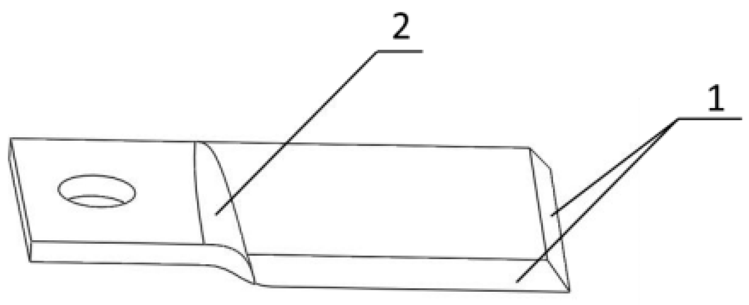
During the harvest of hairy vetch, the stems shall be effectively cut without repeated cutting, and not be entangled on the cutter. Therefore, according to the national standard Technical Requirements for Rotary Mower Blades (GB/T19841-2005) and the actual requirements, a double-blade torsional cutter was designed (
Figure 9). The cutting principle of the cutter was that the stem was cut off by the blade and faces up along the twist knife to avoid the inertia of straw and winding of cutter. The blade thickness was selected as 4 mm, and the twist angle was 5°.
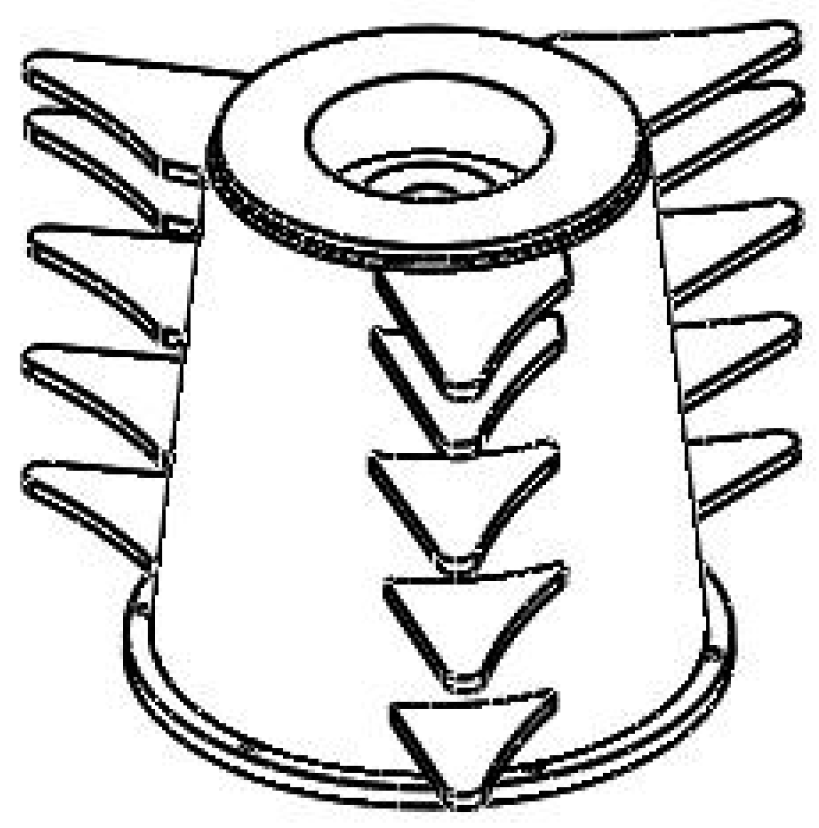
3.2.2. Design of Vertical Drum
Selection of Vertical Drum Shape and Determination of Important Parameters
When the conical drum is working, the plants move in a straight line along the direction of the drum bus and bend upward the circumference of the drum under the action of the flow field around the drum. At the same time, the air flow pushes the cutting plant forward, which is conducive to the cutting machining cutting the bottom of the stem and smoothly entering the next device after cutting reducing blockage and winding. Therefore, the conical vertical drum was selected for reeling. According to that the cutting width of the vetch harvester should be greater than the outermost distance between the tires of the walking part, the cutting width was determined to be 1680 mm. The cutter and the vertical cylinder rotate at the same speed because they rotate in the same axis. In order to ensure the effective transmission of the gear shifting, the linear speed of the vertical drum should be lower than the cutter speed (
va >
vb). According to the test, when the maximum linear speed of the drum
vb = 27 m/s, it can be determined that the diameter of the lower-end face of the conical drum was 280 mm, and the diameter of the upper end face was 220 mm. Additionally, to ensure effective reeling, reduce missed reeling and prevent blockage and winding, the tapered drum
Hb was taken as 300 mm (
Figure 10).
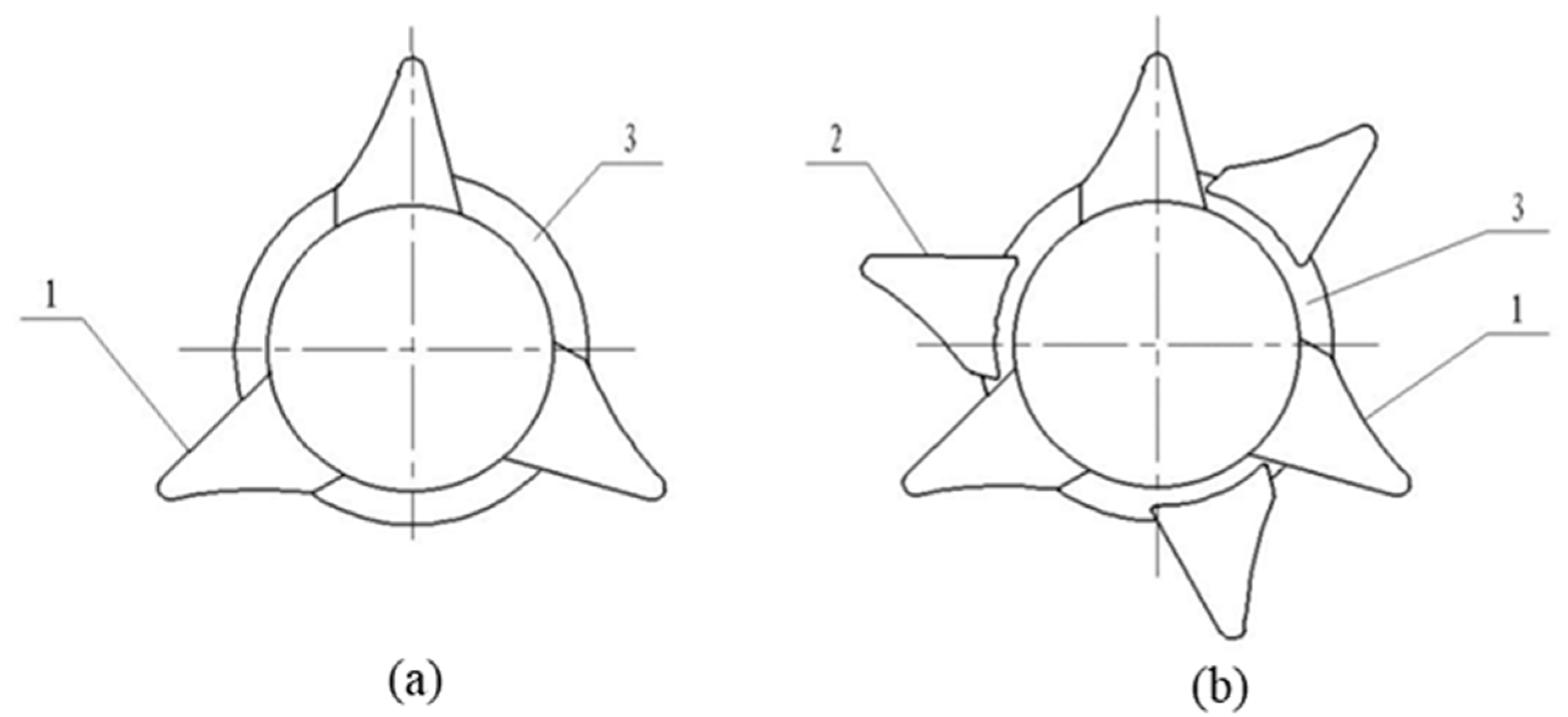
Design of Vertical Reel Structure
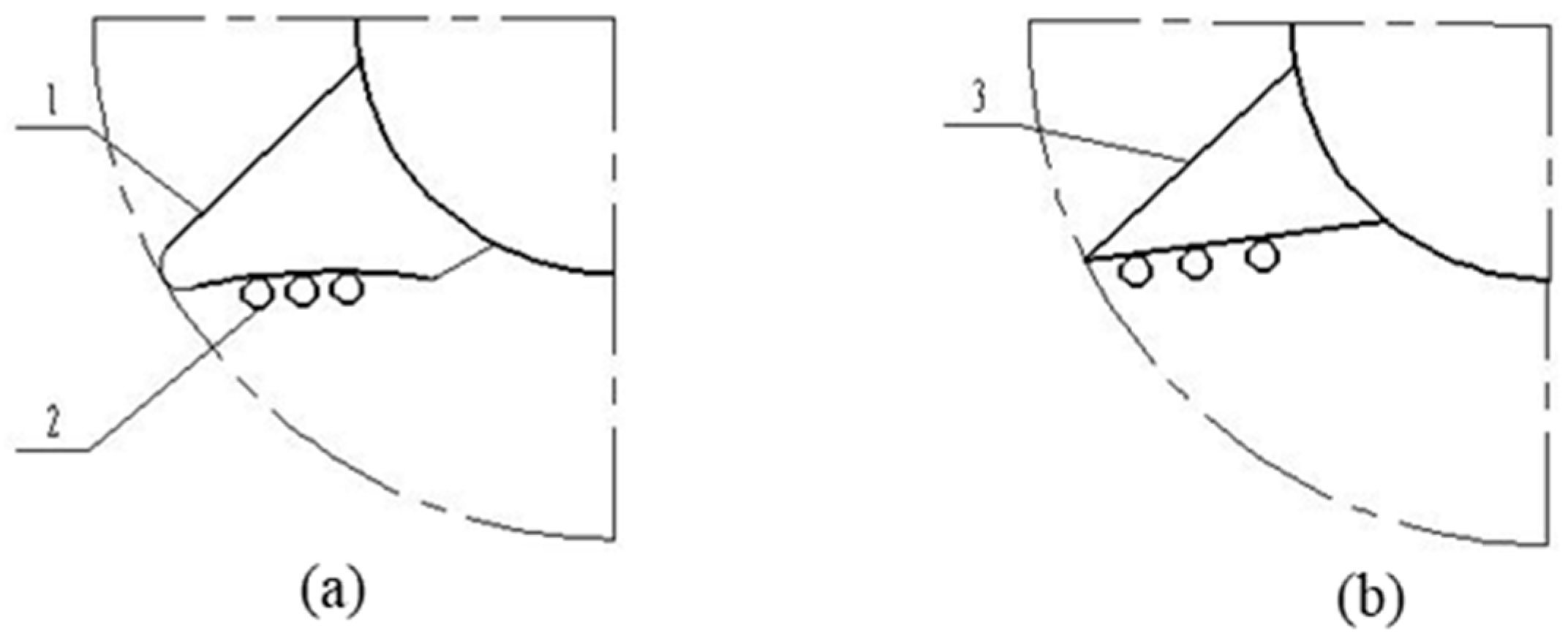
In this study, the roller gear was designed as a triangular structure, and according to the fact that the gear needs a lot of fast reeling during the actual harvest, the gear structure was optimized to meet the problem of easy winding of the long-stem hairy vetch stalk. By comparing the conditions of curved surface gear and common gear, the schematic diagram of the two types of gear is shown in
Figure 11. When the vertical drum rotates, the gears rotate at the same speed. When the linear speed of the paddles is too high, the ordinary paddles easily bounce the cut stems back to the ground, so that the stems are unable to be delivered to the feed inlet in time, causing blockage and winding. The curved surface gear has a curved surface structure. When the gear is rotated, it can gather the stems, effectively preventing the stems from falling back to the ground and be transported to the next device in time.
The arrangement of the gears also affects the working quality. As shown in
Figure 11a, it is a linear arrangement of the gears, which is characterized by the different sizes and distances of each row of gears from top to bottom, so that each row of gears was on the same straight line. As shown in
Figure 12b, it is a nonlinear arrangement of gear shifting, which is characterized by virtue of the fact that each row of gear shifting does not show an equal difference change on the same straight line. Comparing the two arrangement modes, the linear gear shifting can ensure that the stem is moved evenly and orderly to the next device. The non-linear gear is more suitable for hard crops.
According to the diameter, height, and function of the roller, it is determined that the gear shift was distributed in five layers. Three gear-shift teeth of the same size were welded at equal intervals in the circumferential direction of each layer (the angle between adjacent gear-shift teeth is 120°). The size of each gear shift decreases gradually from top to bottom, and the spacing between adjacent gear-shift teeth was different.
Figure 9 shows the schematic diagram of vertical reel.
4. Movement Simulation Analysis of Stem Feeding Process
4.1. Model Construction and Parameter Setting
4.1.1. Discrete Element Model Establishment of Feeding Device
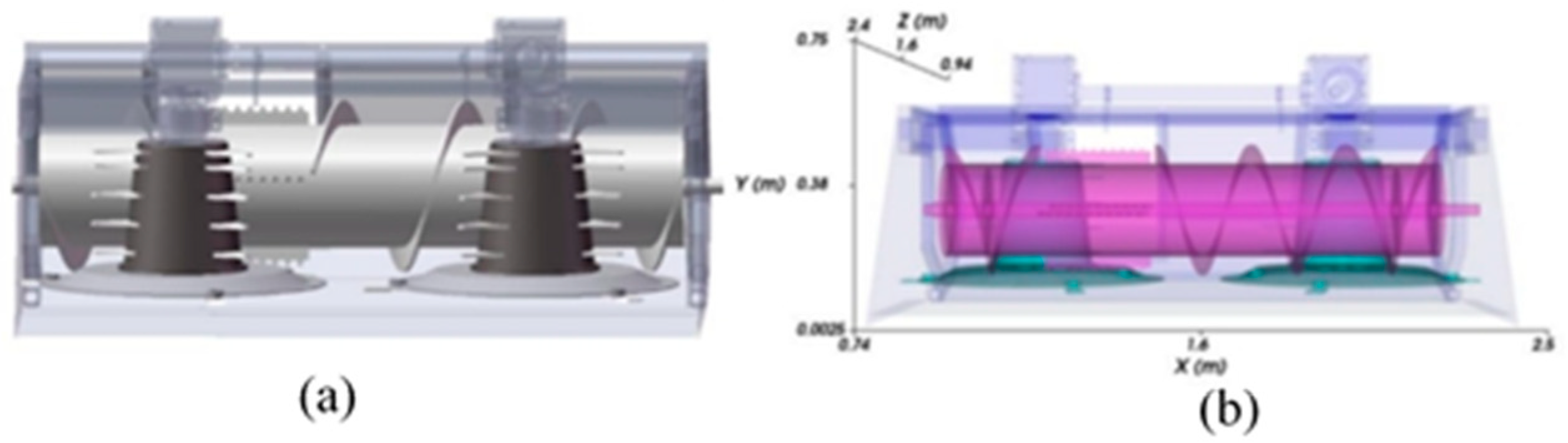
The feeding process and movement of hairy vetch stems were simulated and analyzed by Discrete Element Simulation Software Rocky. The cutting device, vertical drum, spiral conveyor, and frame were visualized to clearly observe the status of stems from entry, reeling, conveying and discharge.
The three-dimensional model (
Figure 13a) of the feeding device was created in SolidWorks and saved in .stl format, then imported into Geometry of Rocky software to generate a discrete element model (
Figure 13b). According to the characteristics of the physical device, set the material properties of feeding device as shown in
Table 2.
4.1.2. Discrete Element Model Establishment of Stem
The Particle stem model was created in Rocky software 4.2 (
Figure 14), setting the diameter of the hairy vetch as 2 mm, the length as 400 mm, the transverse longitudinal ratio as 200. The shape of the stem was set as Straight Fiber. The whole stalk of the hairy vetch is set as 40 segments of flexible connection, and the generation speed of the stem was set as 500 pieces/s in Composition. Neglecting the influence of other impurities on the simulation test, only the interactions between the stem and the feeding device and from stem to stem were considered (
Table 3). Additionally, the whole device was set to use steel.
4.1.3. Establishment of Inlet for Inlet Particles
Inlet was used to set the entry position, direction and time of simulation particles. According to the actual geometry of the feeding device, the inlet was set as Rectangular Inlet. Three Rectangular Inlets were set at different positions in front of the feeding device to simulate the intertwined and disordered entry of stems into the feeding device. The length and width of the entrance of the stem were set according to the theoretical cutting width of the feeding device and the height of hairy vetch plant. Inlet (1) was set to be 0.4 m in length, 1.68 m in width, 90° in alignment angle and 90° in inclination angle. The length was set as 0.4 m, the width as 0.7 m, the alignment angle as 45°, and the tilt angle as 90°. Inlet (3) was 0.4 m long, 1.68 m wide, with an alignment angle of 135° and an inclination angle of 90°.
4.2. Simulation Analysis of Stem Feeding
4.2.1. Simulation of Stem Feeding Process
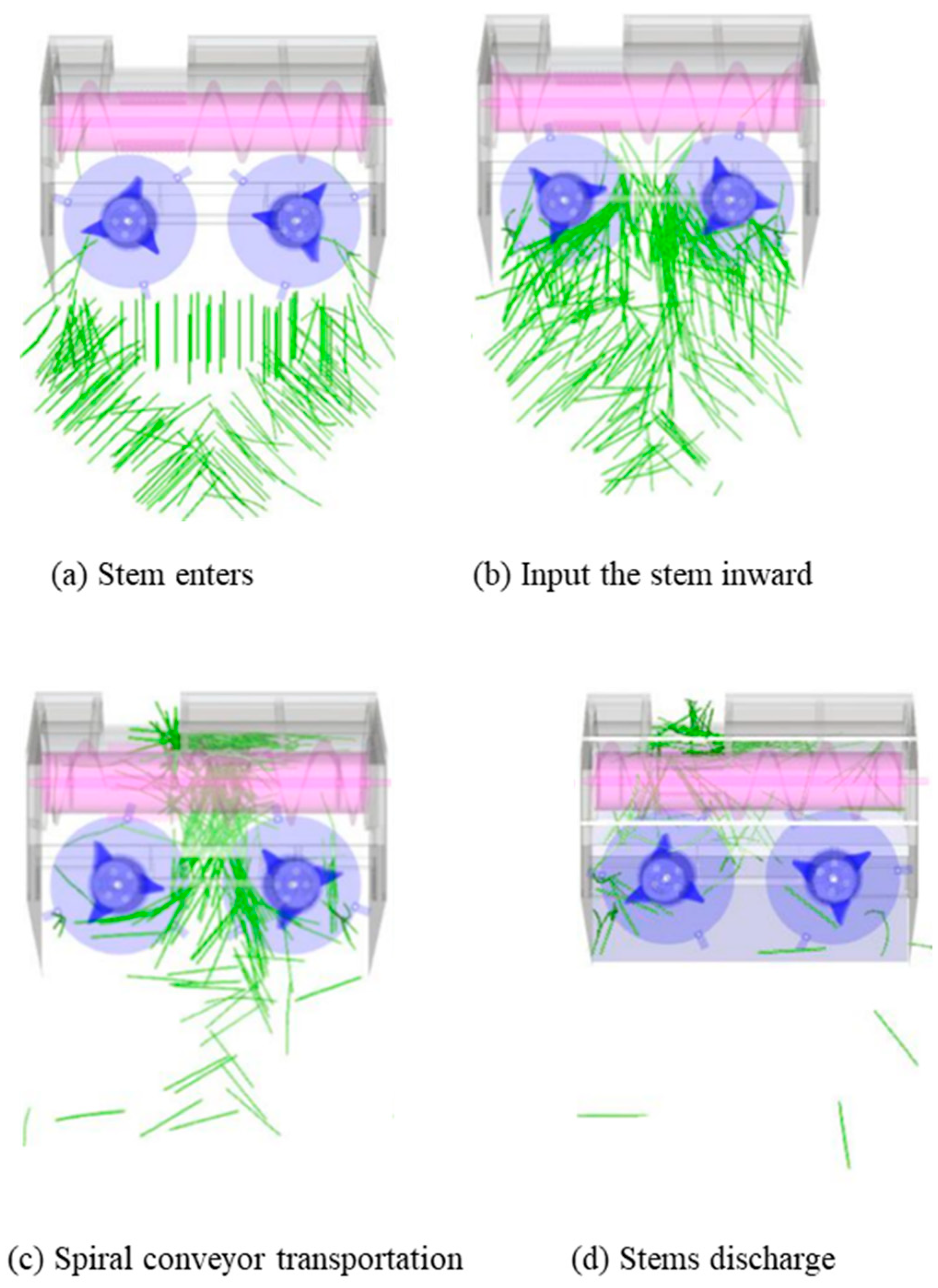
A conventional working condition was used to simulate the actual working state in the field and the agronomic requirements for harvesting: the machine forward speed was 2.5 m/s, the vertical drum speed was 1020 r/min, and the spiral conveyor speed was 300 r/min. The winding and blockage of stems and the movement of stems were analyzed through Rock simulation. By setting the simulation time to 8 s, the time step is 7.38 × 10⁻⁷ s to ensure the continuity and effectiveness of simulation time.
The detailed operation process of stem entering the feeding device was simulated in
Figure 15. All components were visualized to clearly observe the status of each link of stem enters, reeling, conveying and discharge. The stem was in a disordered state before entering the feeding device (
Figure 15a), without obvious entering rules. The feeding device rotates inward during the whole simulation process. As shown in
Figure 15b, the stems enter the device in disorder, the cutting device and the vertical reel device cut the stems at the same speed and reel them inward, and the reel lifts the bottom stem upward at the same time. The stems moves along the spiral blade to the paddle under the action of the auger, so that the stems move quickly from both sides to the output port (
Figure 15c). After the stem reaches the paddle (
Figure 15d), the paddle will drop under the auger, and the stems from different directions will be pulled out of the output port.
4.2.2. Simulation Analysis of Stem Motion
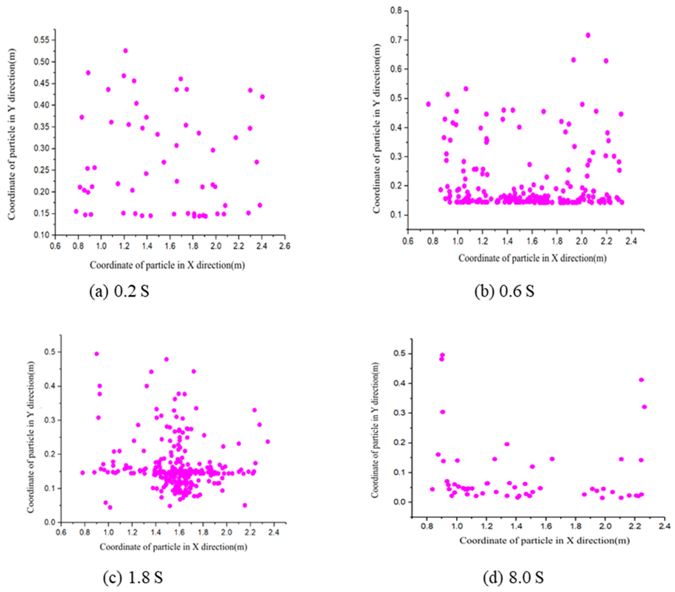
Furthermore, the movement state of the stems in X–Y (
Figure 16) and Z axis direction (
Figure 16) was analyzed in Rocky software. In the X–Y axis direction, at 0.2 s, the stems did not enter the device, and there was no regular discrete distribution between the X–Y ranges (simulating the real material state). At 0.6 s, the stems were stacked (
Figure 16b), which resulted in a large density of stems at the bottom of the feeder and a gradual decrease in the density of at the top. At 1.8 s, when the stems appears between 1.4–1.8 m of X axis and 0–0.1 m of Y axis (
Figure 16c), it indicated that the stems had left the device and were taken out by the Spiral conveyor. At 8.0 s (
Figure 16d), after the simulation, there was a portion of the stems remaining in the feeding device, which represents stem loss, which was usually stacked under the spiral conveyor, mainly because there were no contact between the spiral blades and the stems, and the friction was not enough.
The movement process of the stems in the
Z-axis direction is shown in
Figure 17. At 0.4 s, the stems enter in the device at its initial speed (
Figure 17a), and its absolute translation speed was 0.3–1 m/s due to the collision between stems. At 1.2 s, the absolute translation speed of the stem increases (
Figure 17b), and the speed was in the range 1.8–2.6 m/s. The main reasons were the advance of machines, the cutter cuts and the reel rotates. As shown in
Figure 17c, the absolute translational speed of stems moving with the spiral conveyor was in the range 1.8–3.0 m/s, while the speed of stems stacked at the output port was in the range 0.36–1 m/s. At 8 s (
Figure 17d), the stems have been basically static and stacked under the spiral conveyor and cannot be pulled out. Based on the above simulation results, the stem loss rate was selected as the test index to quantify the effective feeding performance of the feeding device. Stem loss rate performance evaluation index expressions is given by
where:
S is the loss rate, in%;
m1 is the residual amount of stems in the device, in kg;
m0 is stem input quantity, in kg.
4.3. Orthogonal Experiment
4.3.1. Orthogonal Experiment Method
In order to analyze the main factors that affect the winding and congestion of the feeding device, the vertical drum speed was 900–1100 r/min, the machine forward speed was 1.5–3.5 m/s, and the spiral conveyor speed was 250–350 r/min according to the empirical value. The mathematical regression model between vertical drum speed, machine forward speed, and spiral conveyors speed was established by the quadratic regression orthogonal rotational combination test. The test factor-level coding table is listed in
Table 4, and the experimental design plan and response value results are shown in
Table 5 and
Table 6. Each group of experiments was repeated nine times, and the average value was recorded. The low stem-loss rate in the test indicates that the performance of the feeding device was better.
4.3.2. Orthogonal Test Results
Quadratic polynomial regression models between the experimental factors and the performance indexes were established by the data processing software Design Expert V8.0.6.1, and the regression equation between the loss rate of the stems marker of the test finger and the code of the test factors was obtained. As shown in Equation (10), the regression model equations were given by
Table 6 shows the results of the regression model analysis of variance and significance test. The results indicated that the fitting of the stem loss rate was extremely significant (
p < 0.01), the
R2 = 0.9706, and the lace of fit (
p = 0.6856) was not significant. There were no significant out-of-fit values in the regression equation, which was in good agreement with the actual situation. The primary and secondary order of the influence of each factor on the stem loss rate was spiral conveyor speed, machine forward speed, and vertical drum speed.
4.3.3. Optimization of Working Parameters
Various factors had a significant impact on the performance of the feeding device. In order to obtain the best working parameters, the vertical drum speed, machine forward speed, and spiral conveyor speed need to be optimized. In actual harvest operations, the stem loss rate y should be as low as possible. The parameter optimization conditions were given by
The optimized working parameter combination was as follows: the vertical drum speed was 1037.5 r/min, the machine forward speed was 2.76 m/s, and the spiral conveyor speed was 348.88 r/min. The measurements were repeated five times, and the averages were taken as the stem loss rate performance indexes. The results showed that the loss rate of feeding device was 2.38%. It suggested that the optimized parameter combination could more effectively improve the harvesting performance of the feeding device.
5. Performance Test
The performance test was conducted in Jinzhou City, Shijiazhuang City, Hebei Province on 28 June 2020 at a temperature of 20 °C–23 °C. The test material was the Turkmen hairy vetch, with an upright length of 40–60 cm, a creeping length of 1–3 m, a fresh weight yield of 38.76 t/hm2, and an average moisture content of 65.12%.
During the test, according to the optimal parameters, the vertical drum speed was set to 1037.5 r/min, the machine forward speed was set to 2.76 m/s, and the spiral conveyor speed was set to 348.88 r/min. The straw loss rate, actual cutting width, cutting stubble height, over stubble loss rate and missing cutting loss rate were tested for the hairy vetch harvester, by referring to the measurement indicators in rotary mowers (GBT10938-2008). Before the test, the water content of plant and fresh weight of hairy vetch were measured.
Test results showed in
Table 7. The average value of the three experiments was taken as the test result. The straw loss rate was 3.00%, the actual cutting width was 1.66 m, the cutting stubble height was 6.41 m, the over stubble loss rate was 0.45%, and the missed cutting loss rate was 0.20%. The above test indicators meet the requirements of the national standard GBT10938-2008.
6. Conclusions
The physical properties of the hairy vetch stems were studied, and its mechanical properties were tested. Radial compression test results showed that the average value of the critical pressure of the stem was 8.59 N, the compressive strength was 0.22 MPa, and the elastic modulus was 0.27 MPa. Axial tensile load of the stem was 12.77 N, the tensile strength was 2.8 MPa, and the elastic modulus was 169.35 MPa. Additionally, the bending load of the stem was 0.54 N, the bending strength was 9.98 MPa, and the bending shear modulus was 465.01 MPa.
The ternary quadratic regression orthogonal rotation combination test was established with the vertical drum, the machine forward speed, and the spiral conveyor speed as the test factors and the stem loss rate as the test index. The simulation results showed that when the vertical drum was 1037.5 r/min, the machine forward speed was 2.76 m/s, the spiral conveyor speed was 348.88 r/min, and the straw loss rate was 2.38%.
The field performance test showed that the straw loss rate was 3.00%, the actual cutting width was 1.66 m, the cutting stubble height was 6.41 m, the over stubble loss rate was 0.45%, and the missed cutting loss rate was 0.20%, and thus, the test indicators meet the requirements of the national standard. That indicates the design performance of the feeding device is stable and suitable for harvesting mature hairy vetch.
(1) For the determination of physical characteristics parameters of long-stem crops such as hairy vetch, it is still necessary to continue to study, analyze and summarize a set of physical theory system and practical methods that can be applied to long-stem crops. (2) The cutting device designed in this paper has the phenomenon of grass returning during the operation. It is recommended to combine the working principle and operation requirements of the feeding device, optimize the structure of the cutter, and add the anti-return device to improve the harvesting efficiency of the feeding device.


