Article

Design and Experimental Study of Bionic Reverse Picking Header for Fresh Corn

College of Biological and Agricultural Engineering, Jilin University, Changchun 130022, China
*
Author to whom correspondence should be addressed.
Agriculture 2023, 13(1), 93; https://doi.org/10.3390/agriculture13010093
Submission received: 2 December 2022 / Revised: 24 December 2022 / Accepted: 26 December 2022 / Published: 29 December 2022
(This article belongs to the Section Agricultural Technology)

Abstract

:
Influenced by the maturity and material properties, fresh corn has problems, such as low picking rate, high energy consumption and high damage rate during mechanized harvesting. For the above problems, a bionic reverse picking header was designed using the post-ripening morphology of corn and the hand-picking behavior as bionic prototypes. Model analysis and structural design of the key components of the header, including the reeling device, clamping device and picking device, were carried out. Based on the designed header prototype, single-factor tests and Box Behnken tests were conducted to explore the factors affecting the working performance of the picking header. The optimal structural parameters and working parameters were determined by response surface method. The results showed that with the increase in the clamping picking device speed and the stalk feeding speed, the picking rate first increased and then decreased. The interaction between feeding speed and cutter position had the most significant effect on the picking rate. The unique reverse picking mechanism and flexible device of the header could avoid collision and damage to the corn ears. The highest picking rate was achieved when the clamping picking device speed was 416.81 rpm, the stalk feeding speed was 1.13 m/s, and the cutter position was −5.45 cm.

1. Introduction

In recent years, with the improvement in living standards and dietary structure, there has been a more stringent demand for crops. As the corn ear from late milk-ripe stage to early dough stage, fresh corn has gained popularity for its high nutrition and excellent taste [1,2,3,4]. Compared to regular corn, planting fresh corn can increase the benefits by more than 50% and cost less [5]. Fresh corn has become a “golden crop” in food, economy and industry with its huge market demand and high planting profit [6,7,8]. It is widely cultivated all over the world, and its planting area and yield are growing day by day, with an annual growth of more than 30% in China alone [7,9]. However, the taste and nutritional value of fresh corn are closely related to its growth state. There is a very short “optimal harvesting period”, which places high demands on the harvesting efficiency of fresh corn [10,11]. The low efficiency of manual harvesting seriously restricts the quality of fresh corn and the expansion of the planting scale, so the promotion of mechanized harvesting of fresh corn is extremely urgent [12,13].
Ear picking is the first technical process of corn mechanized harvesting. As an important working part of the corn harvester, header is the part which has the greatest impact on the ear quality [14]. Domestic and foreign corn harvesters mostly use the traditional forward-stretching header, which operates mainly with the help of stalk drawing rollers and snapping plates. A great deal of research has been carried out on this forward-stretching header. The 60 series picking headers (Oxbo International Corporation, Roosendaal, The Netherlands) generally used flexible technology and materials to reduce the impact of the working parts on the corn ears, and tapered knife rolls to reduce the impact speed of the stalks when feeding [15]. In order to solve the problem of high loss and damage rates, CLASS changed the traditional snapping plate to a curved plate with a certain inclination angle to reduce the stress on the corn ears. Taking loss rate and power consumption as indexes, Chinese scholars have carried out optimization tests on the roll structure and working parameters of the forward-stretching header [16], and determined the optimal combination of working and structural parameters of the clamping device [17].
At present, the mechanized harvesting of fresh corn is mainly accomplished by these forward-stretching headers, whose structural and working parameters are designed and optimized with the morphological characteristics and mechanical properties of the mature corn ears. However, during the harvest period, fresh corn has a high moisture content and the internal material of the kernels is pulpy, resulting in low mechanical strength of the corn ears [18,19]. Forward-stretching picking is mainly performed by rubbing and squeezing, which not only causes serious damage to the corn ears, but also consumes a lot of energy [20,21]. The damaged kernels are highly susceptible to mold and accumulate toxic substances, which seriously affect the quality of fresh corn and subsequent storage, processing and marketing [22,23,24].
In order to reduce the damage to fresh corn ears during picking and reduce the energy consumption, a bionic reverse picking method is proposed to pick corn ears by a combination of reverse bending, twisting and stretching. This method can not only reduce the damage to fresh corn ears, but also retain the intact corn stalks, realizing full-value corn harvest. Based on this method, a bionic reverse picking header for fresh corn harvesting was designed. Model analysis, parameter calculation and structural design of the main working parts of the bionic header were carried out. The optimal working and structural parameters of the bionic header were obtained by single-factor tests and Box-Behnken tests. The bionic header designed in this study provides an excellent way to achieve low damage low energy consumption for ear picking, and the test results also provide a theoretical basis and design reference for subsequent optimization.

2. Materials and Methods

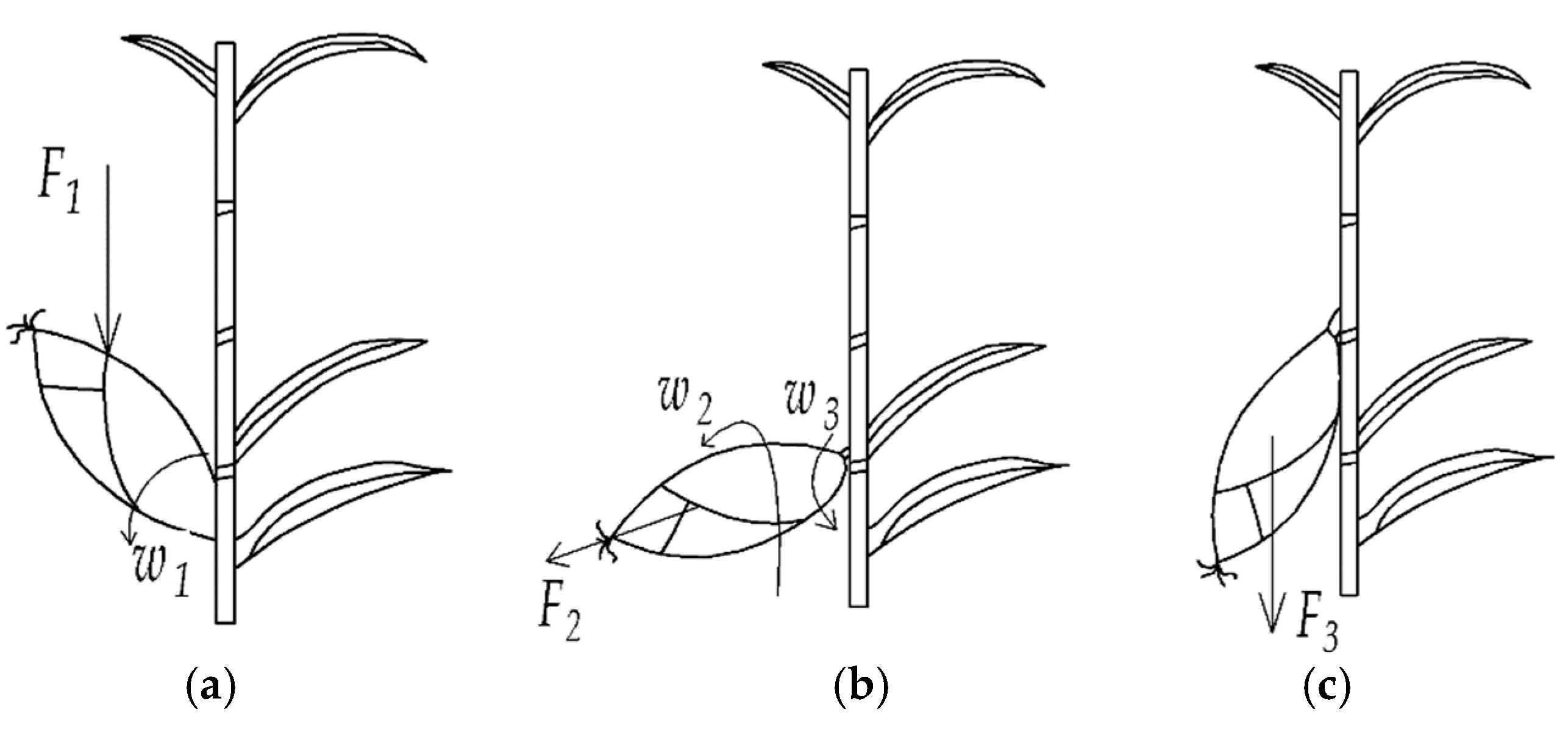
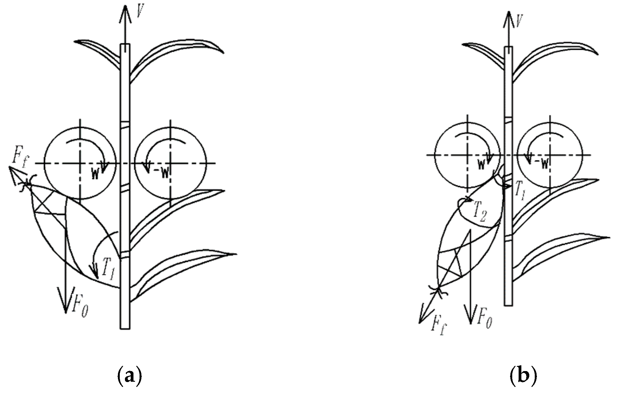
2.1. Bionic Reverse Picking Method

Bionics takes morphological structures and living phenomena in nature as models and extracts their scientific principles for direct or indirect bionic design, ultimately realizing the enhancement of the functions of agricultural machinery components. The bionic models involved in this study are biological model and living model. The biological model is the natural shedding form of corn ears after maturity, and the living model is the harvesting behavior of human’s hand-picking corn ears. Based on the natural shedding behavior of corn ears after maturity, the process of hand picking is as follows:
First, the corn ear is held by hand and a vertical downward bending force F1 is applied to the corn ear, causing the ear to bend downward w1 at the center of the peduncle (Figure 1a). Afterwards, a twisting action w2 is applied with the centerline of the corn ear as the axis. The bending force F2 is continuously applied during this process, causing the corn ear to bend downward with w1 (Figure 1b). At this stage, the peduncle is subjected to both bending and twisting forces and breaks under these actions, leaving only a few fibers connecting the ear to the corn stalk. Finally, a downward stretching force F3 is applied by hand to the corn ear, causing the fibers to break and the ear to be picked (Figure 1c).
Stretching fracture and bending fracture tests were performed on corn peduncle. This test used the WDW-20 microcomputer equipped with an STC-100 sensor to control the electronic universal testing machine and the self-made corn mechanics supporting fixture. The fresh corn was at the late milk-ripe period (corns with an average moisture content of 75 ± 5%). The tests results showed that the fracture force of the corn peduncle in forward stretching ranged from 217–797 N with an average value of 515.6 N. The fracture force when subjected to bending was 10.26–185.6 N, with an average value of 56.9 N. It can be seen that the force required to break corn peduncle by forward stretching was much higher than that for reverse bending.
Hand picking is a reverse picking process in which the corn ear is subjected to bending, twisting and stretching at the same time. Compared to forward stretching picking, the corn peduncle is more likely to fracture and the force required is less. In addition, the bionic reverse picking method incorporates the downward gravity of the corn ear. During the actual operation, the force applied on the corn ear is less than F1, F2 and F3. Therefore, bionic reverse picking is an excellent method with low force requirements and low power consumption.

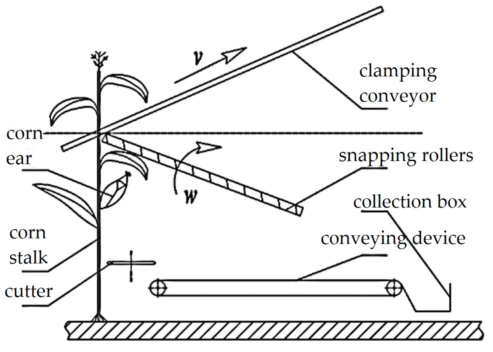
2.2. Structure and Working Principle of Bionic Reverse Picking Header

The essential difference between the bionic reverse picking header and the traditional forward picking header is the different direction of relative movement of the corn ears and corn stalks. During the picking process, the traditional forward picking header holds the peduncle of the corn ears by means of snapping rolls or plates to limit the movement of the corn ears. Afterwards, the corn stalks are stretched downward, causing the corn ears to move upward relative to the stalks and eventually to pick the corn ears. The bionic reverse picking header uses the opposite motion: stretching the ears downward while fixing the stalks, or fixing the ears while lifting the stalks upward, ultimately separating the corn ears from the stalks (Figure 2).
The overall structure of the bionic reverse picking header is shown in Figure 3, which mainly includes the mounting frame, lifting platform, trailer, picking device, lifting device, collection box and hydraulic driving device. Among them, the picking device includes reeling device, clamping device, snapping roller, cutter and conveying device, etc. The bionic header is hooked up to the tractor by side traction. It is driven by the tractor through full hydraulic operation in the field to harvest the corn located on the side of the tractor.
During operation, the cutter cuts the corn plants at the root position, after which the lifting device holds the stalks and lifts it upward. As the stalks rise, the corn ears reach the position of the snapping rollers and are restrained by the snapping rollers. The snapping rollers are equipped with spirals which can transport the corn ears backwards, further increasing the relative movement between the corn ears and stalks. When the relative movement of the cob ears and stalks reaches the maximum, the peduncles break off allowing the corn ears to fall to the conveying device. Afterwards, the picked corn ears are conveyed to the collection box by the conveying device, while the stalks continue to be hold and moved by the lifting device until they are removed from the cutting table.

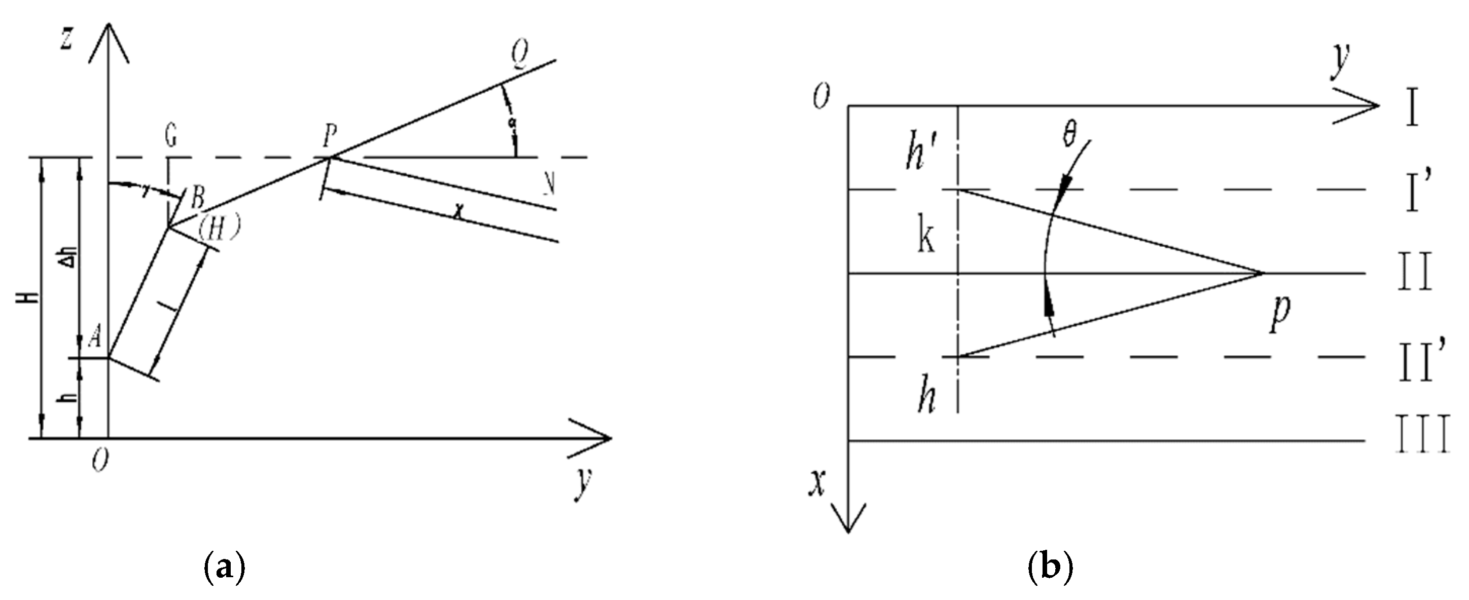
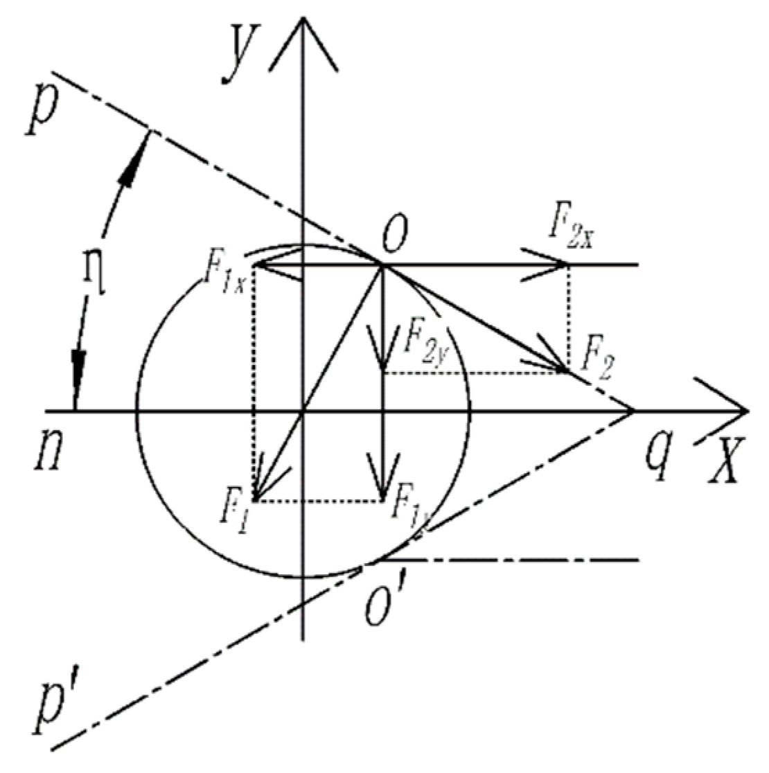
2.2.1. Geometric Model and Parametric Analysis of Picker

The stalks of corn plants may be tilted forward, backward or bent due to external uncontrollable environmental factors during seeding or growth. In the process of ear picking, the state of corn stalks during feeding has a great influence on the picking efficiency and harvest quality, so it is essential to ensure the orderly feeding of corn stalks. In order to ensure the picking quality of the bionic reverse picking header, a chain-type reeling device was designed and the relevant parameters were calculated by extracting the geometric model.
Take the vertical direction as the z-axis, take the opposite direction of the harvester′s advance as the y-axis, determine the x-axis according to the right-hand rule, and establish the coordinate system. A simplified geometric model of the reeling device of the bionic reverse picking header is shown in Figure 4, where (a) is the projection of the reeling device in the yoz plane, (b) is the projection of the reeling device in the xoy plane, hp and hp′ are the reeling devices, AB is the corn ear, and I, II and III are the corn planting rows. To ensure successful reeling, the height of the end of the reeling device needs to be higher than the highest point of the corn ear.
H l H P sin α h + l cos γ
In order for the operating range of the reeling device to cover all growing positions of the corn, the front end of the reeling device needs to reach the midline of the corn planting row. By setting the corn planting row spacing as Δt, the following conditions can be obtained:
l hp sin θ Δ t 2
According to the projection relationship, the above equations are combined to obtain:
l h p sin θ = l H P cos θ cos α sin θ = l H P tan θ cos α Δ t 2
As a result, the design parameters of the reeling device can be derived as
l H P H h l cos γ sin α θ arctan Δ t 2 l H P cos α
where lHP is the effective working length of the reeling device (mm); l is the length of corn ear (mm); H is the height of the reeling device (mm); h is the ear height of corn plant (mm); α is the tilting angle of reeling device (°); γ is the angle between corn ear and stalk (°); and θ is the opening angle of reeling device (°).
It can be seen that the effective working length of the reeling device is related to the ear height of corn plant, the length of corn ear and the angle between the corn ear and the stalk. The opening angle of reeling device is related to the corn planting row spacing.

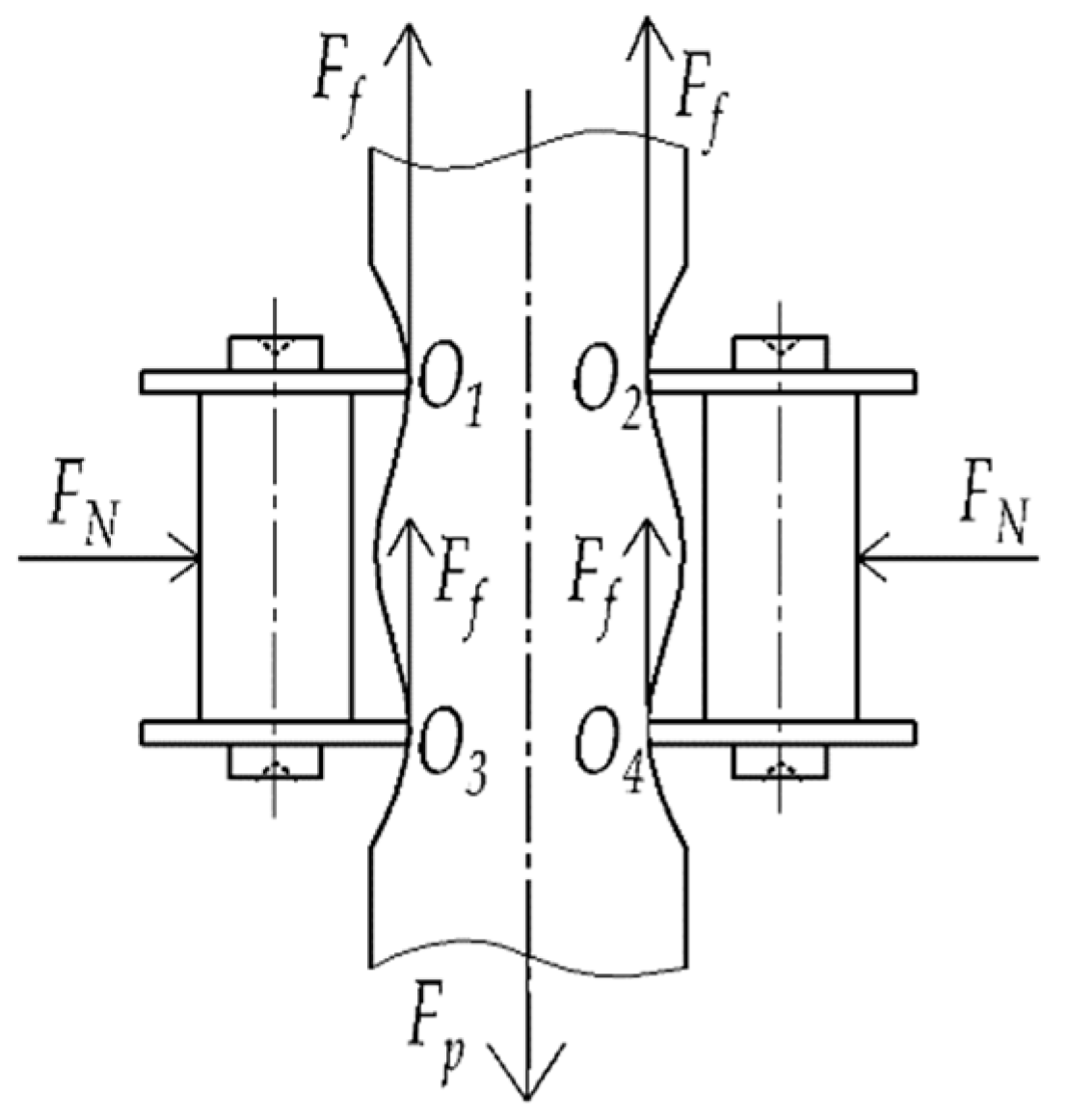
2.2.2. Effective Feeding and Clamping Conditions of Clamping Device

The corn stalks are conveyed by the reeling device and reach the front of the clamping device. Effective feeding of the stalks into the clamping device is a prerequisite to ensure subsequent picking. To determine the conditions for feeding the clamping device, a geometric model of the corn stalk and the clamping device was extracted, as shown in Figure 5.
A coordinate system was established with the center of the stalk as the origin and the x-axis and y-axis are shown in the figure. The critical position of corn stalk feeding into the clamping device was analyzed. In the figure, pq and p′q are the front part of the clamping device, ∠pqp′ is the feeding angle of the clamping device whose value is 2η, o and o′ are the contact points between the corn stalk and the clamping device. F1 is the squeezing force of the clamping device on the stalk, with the direction perpendicular to pq. F2 is the friction force between the clamping device and the stalk, whose direction is along the movement direction of the clamping chain. Suppose the friction coefficient between the stalk and the clamping device is f, then the following relationship exists at the position of the contact point o:
F 2 = f F 1
Decomposing F1 and F2 in the x and y directions gives F1x, F1y and F2x and F2y, respectively (with the same result at the symmetry point o′). The condition that enables corn stalks to be fed successfully into the clamping device is that the component force of the frictional force in the x-direction is greater than that of the squeezing force, which is:
F 2 x + F 2 x F 1 x + F 1 x
F 1 sin η > f F 1 cos η
According to the following model of friction coefficient of corn stover, we can obtain:
f = d 5 w + 39 k + 888 × 10 3
η > arctan d 5 w + 39 k + 888 × 10 3
where d is the diameter of corn stalk (mm); w is the moisture content of corn stalk (%); and k is the position of the ear on a corn plant (section k from the top).
It can be seen that the feeding angle of the clamping device is related to the stalk diameter, moisture content and clamping position. Therefore, the effective feeding conditions of the clamping device can be determined based on the relevant parameters of the field corn.
The bionic reverse picking header lifts the corn stalks by the clamping device, allowing relative movement between the stalks and the corn ears. In this process, the force exerted by the snapping roller on the corn ears and the friction exerted by the clamping device on the stalks maintain a balance. Therefore, the ability of the clamping device to provide sufficient friction and effective clamping is necessary to complete the ear picking.
Figure 6 shows the forces on the corn stalk when it is lifted by the clamping chain. In the figure, F is the combined force of the snapping roller and the gravity of the corn plant. FN is the clamping force applied by the clamping device. Points O1, O2, O3, and O4 are the contact points between the clamping chain and the corn stalk, and the positive pressure on each point is one-fourth of the clamping force FN. The combined force of the friction at these contact points is balanced by the force F. The following conditions can be obtained from the corn stalk friction coefficient model f.
F f = f F N 4
F N = F d 5 w + 39 k + 888 × 10 3
Since the strength of the corn stalk is lower than that of the clamping chain, the stalk will be deformed during the clamping and lifting process. In the vertical direction, in addition to the friction, the corn stalk is also subjected to the vertical component of FN. Therefore, the clamping force FN obtained according to Equation (11) is completely sufficient.
From the above equation, it can be seen that the clamping force applied to the stalk is related to the force of the snapping roller, the gravity of the corn plant, the stalk diameter, moisture content and clamping position. Therefore, the clamping force required for corn ear picking can be calculated based on the relevant parameters of the field corn.

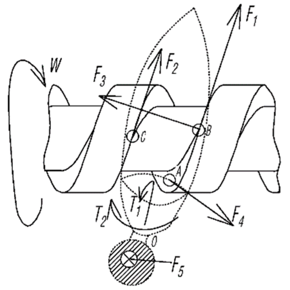
2.2.3. Model Analysis of Picking Device

The picking process of the bionic reverse picking header is a 2-step process as follows. In the initial stage (Figure 7a), the corn stalk is lifted upwards by the clamping device. The corn ear comes into contact with the snapping roller and is subjected to the vertical downward picking force F0. In addition, the corn ear rubs against the surface of the snapping roller, and the friction assists in the picking process. To avoid blockage between the snapping rollers, the picking rollers are set to rotate in the direction of w as in the figure, so that the snapping rollers can pluck the corn ear outward during the picking process.
In the next stage (shown in Figure 7b), the peduncle is bent downward by the bending moment T1, and the rotation of the snapping roller applies a torque T2 to the corn ear to twist it. At the same time, there is also a frictional force Ff and a picking force F0 exerted by the snapping rollers. The corn peduncle is fractured under the combined action of bending, twisting and stretching, and finally the corn ear is picked.
The spiral rollers are used for the picking device designed in this study, and the situation of corn ear in contact with spiral snapping roller is shown in Figure 8. The spiral snapping roller rotates at w. The corn ear is subjected to frictional forces F1 and F2 at contact points B and C. Due to the presence of the spiral the corn ear moves forward by force F3. As the corn stalk is continuously raised by the lifting force F5 exerted by the clamping device, the peduncle is bent by the bending moment T1. At this time, the bottom of the corn ear is in contact with the side surface of the snapping roller at point A. The ear twists T2 under the friction F4 exerted by the snapping roller.
To achieve the above function, it is necessary to ensure that the corn stalk can pass between the snapping rollers while the corn ear does not pass. Therefore, the snapping roller spacing needs to be larger than the diameter of the corn stalk and smaller than the diameter of the large end of the corn ear. To facilitate the configuration, the snapping rollers are set to linkage, the projection of one roller is facing the groove of another roller. By optimizing the structural parameters of the snapping roller, it is determined that the diameter of the roller is 100 mm, the pitch is 80 mm, the depth of the spiral groove is 20 mm and the width of the groove is 40 mm.

2.3. Picking Test of Bionic Reverse Picking Header

To verify the operational quality of the designed bionic reverse picking header, a prototype machine was developed. Based on this prototype, the ear picking test was carried out. The deficiencies in the design were explored and corrected through tests, and the optimal working parameters and structural parameters were obtained.

2.3.1. Materials of Test

The corn variety used in the picking test was JNX 7, an excellent variety of fresh corn bred by the Jilin Provincial Academy of Agricultural Sciences. This variety had good taste, high yield stability and good resistance. It took 92 days from seedling emergence to harvesting and was widely grown in the northeast China.
Fresh corn for the test was collected in late August 2021 at Jilin University Agricultural Experiment Base (43°56′46″ N, 125°14′52″ E), when the fresh corn was at late milk-ripe stage. Corn plants with intact corn ears were cut from the roots and stored at constant temperature (25 ± 1 °C) and humidity (60 ± 5% RH) for subsequent use.

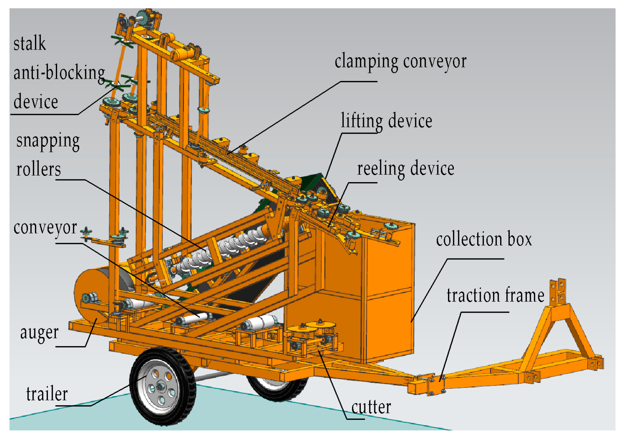
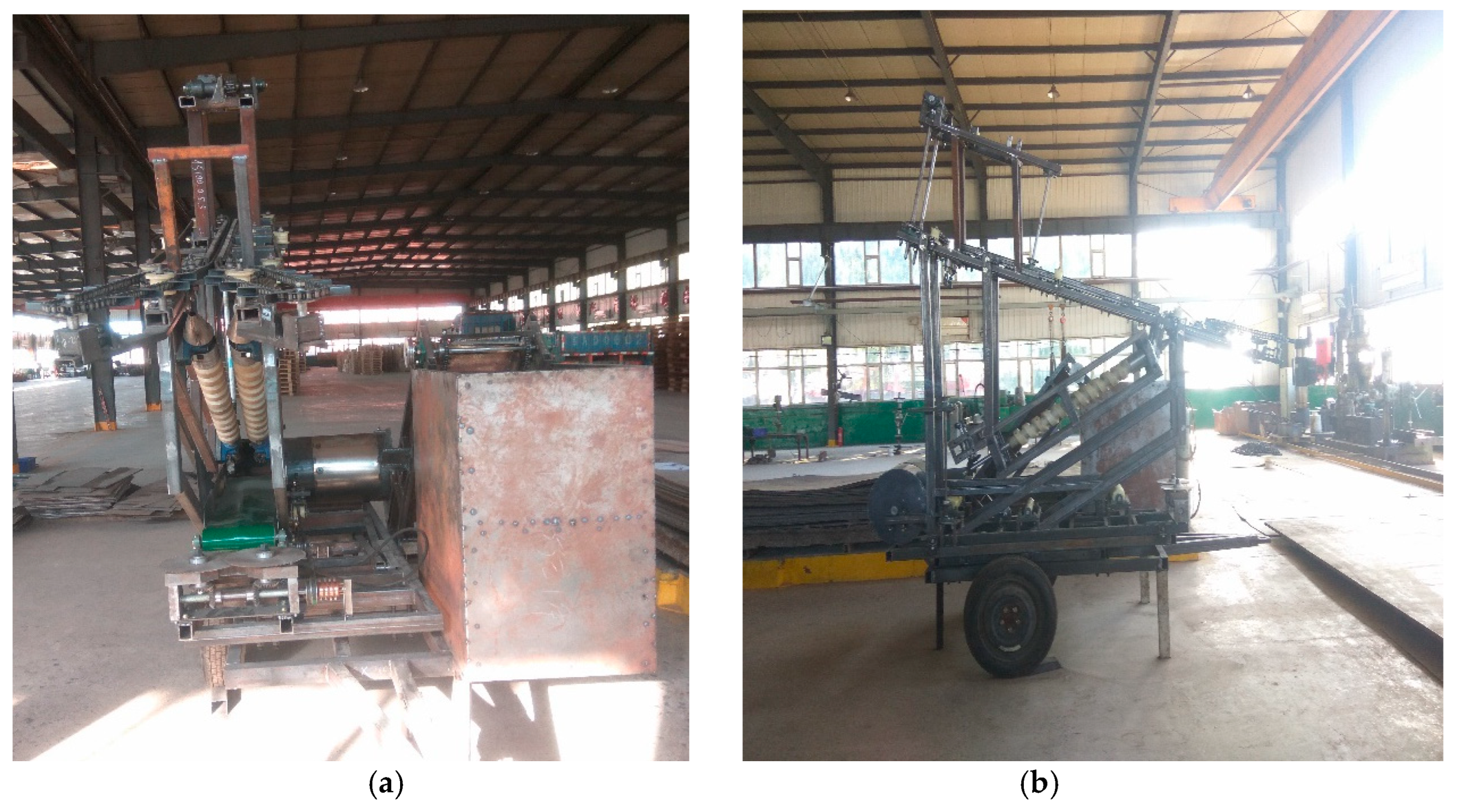
2.3.2. Prototype Machine

After the steps of theoretical analysis, 3D model construction, ANSYS simulation and optimization, 2D drawing, parts processing, assembly and debugging, the bionic reverse picking header was assembled in July 2021 at Changchun Yongheng Automotive Driving Mounting Co., Ltd., Changchun, China. The prototype processing period was 5 months, followed by a 2-month commissioning period. The bionic reverse picking header prototype is shown in Figure 9.
After the prototype was assembled, the clamping force of the clamping device was adjusted using an HP-500 tensiometer (measuring range −500~500 N, accuracy 0.1 N). Based on the corn plant parameters, the effective clamping force for the clamping chain was calculated by Equation (11) to be greater than 19.71 N. By changing the position of the adjusting nut of the spring on the clamping chain, the preload force of the spring on the clamping chain was changed to ensure that the clamping force at each position measured was greater than 19.71 N.
The bionic reverse picking header prototype was fully hydraulically driven. In order to test the speed adjustment range and speed stability of hydraulic motor, DT-2234B photoelectric speedometer (measuring range 5–99,999 rpm, accuracy 0.1 rpm) was used to measure the speed of hydraulic motor. After the hydraulic system had warmed up for 30 min, the speed was measured continuously for 30 min. The speed range of the hydraulic motor was finally determined to be 0–750 rpm, and the operation was stable in accordance with the design requirements.

2.3.3. Design of Test

The picking rate and kernel loss rate were the most intuitive and effective indicators to evaluate the performance of the ear picking header. According to the working principle of the bionic reverse picking header and related studies [25,26,27], the clamping−picking device speed, corn stalk feeding speed and cutter position were the main factors affecting the picking rate and kernel loss rate. Among them, the speed of the clamping device and the picking device were kept synchronized and adjusted by changing the speed of the hydraulic motor. In order to simulate the real situation during corn harvest, the corn plants were fed into the bionic reverse picking header together with the roots, with adjustable feeding speed. The position of the cutter was adjusted by the mounting holes reserved during processing (located directly below, 10 cm in front of and 10 cm behind the feeding inlet of the clamping device).
To further investigate the effects of the above factors on the performance of the bionic reverse picking header, single-factor tests were first conducted.
First, a single-factor test of clamping−picking device speed was conducted. The feeding speed was fixed at 1 m/s, the cutter was temporarily inactive, and the speed of the clamping−picking device was set to 250 rpm, 300 rpm, 350 rpm, 400 rpm and 450 rpm respectively. In the test, 10 corn plants were fed sequentially into the bionic reverse picking header, one plant at a time, and replicated five times. After each test, the number of successfully picked corn plants was counted, and the corn kernels shed from the corn ears were collected and weighed. The picking rate and kernel loss rate were calculated by the following equations:
R P = n N × 100 %
R L = m M × 100 %
where RP is the picking rate (%); n is the number of corn plants successfully picked; N is the total number of corn plants in the test; RL is the kernel loss rate (%) (include the loss grains, the broken and damaged grains); m is the mass of kernels shed from the corn ears (kg); and M is the total weight of the kernels of the corn ears (kg).
The results of the single-factor test for the clamping-picking device speed are shown in Table 1. It can be seen that the optimum value occurred at 400 rpm for the rotational speed of the clamping-picking device. Therefore, the subsequent tests were arranged centered on 400 rpm, with an upper limit of 450 rpm and a lower limit of 350 rpm.
Referring to the travel speed of the tractor during field harvesting, the stalk feeding speed was determined as 0.6 m/s, 1.2 m/s, 1.8 m/s, 2.4 m/s and 3.0 m/s. A single-factor test of corn stalk feeding speed was conducted. In the test, the clamping-picking device speed was set as the optimal value of 400 rpm for the above test, and the cutter was still temporarily inactive.
The results of the single-factor test of the stalk feeding speed are shown in Table 2. It can be seen that the optimal value appeared in the single-factor test when the stalk feeding speed was 1.2 m/s. Considering that the feeding speed at 1.8 m/s and 2.4 m/s also showed a large value of 80% in the single-factor test, the range of stalk feeding speed was determined as 0.6~2.4 m/s.
The results of single-factor tests provide data support for selecting the level of each factor in a Box−Behnken test. To explore the interaction between factors and obtain the optimal parameter combination, a Box–Behnken design (BBD) with three factors and three levels was implemented. Based on the results of the single-factor test, the coding levels of the test factors are shown in Table 3. The test scheme was designed according to the coding level table. A total of 15 tests were conducted, which included 12 factor combination tests and 3 central point replicates.

2.3.4. Data Analysis Method

The results of the Box-Behnken test were statistically analyzed using Design-Expert 2021 software (Stat-Ease Inc., Minneapolis, MN, USA). The response surface method (RSM) was applied to analyze the test results. Quadratic regression models were evaluated through the coefficient of determination (R2) [28]. The significance of each factor for the evaluation indexes was determined using the analysis of variance (ANOVA), and the significance level was p = 0.05. Subsequently, response surfaces for interactions were generated. Finally, the optimal working and structural parameters of the bionic reverse picking header were determined.

3. Results and Discussion

In this section, the results of the single-factor and Box–Behnken tests are presented. The effects of clamping picking device speed and stalk feeding speed on picking rate and kernel loss rate were analyzed, and the interaction between clamping picking device speed, stalk feeding speed and cutter position were discussed. The regression model and the optimal combination of parameters were obtained by ANOVA on the test results.

3.1. Analysis of Single-Factor Test Results

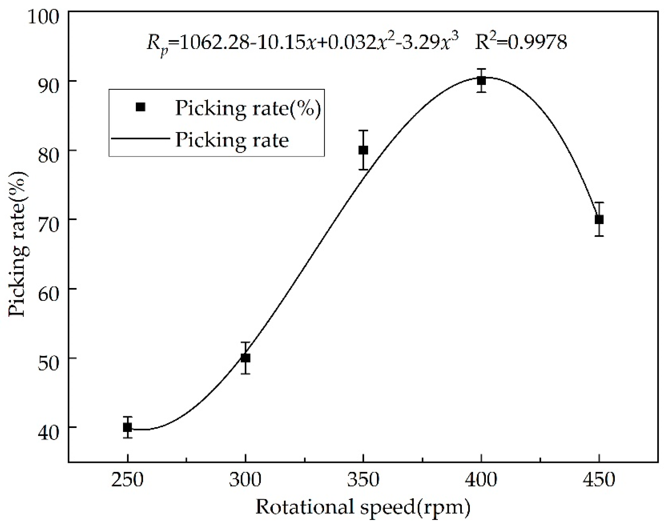
3.1.1. Clamping-Picking Device Speed

In the single-factor test, the rotational speed of the snapping roller and clamping device was adjusted by varying the rotational speed of the hydraulic motor from 250 rpm to 450 rpm. From the test results in Table 1 and Figure 10, it can be seen that the lowest picking rate of 40% was achieved when the clamping-picking device speed was 250 rpm. At this time, because the speed of the corn stalks carried by the clamping device was too low, the corn ears fed into the picking device lacked kinetic energy. It was difficult to break the peduncles by the tension brought about by the difference in movement direction. In addition, the low rotational speed of the snapping rollers made the corn ears become clogged between the snapping rollers and difficult to be plucked out, affecting the picking rate of subsequent ear picking.
As the rotational speed increased, the corn stalks and ears gained more kinetic energy. The picking rate of the bionic header gradually increased and reached a maximum of 90% near 400 rpm. When the rotational speed exceeded 400 rpm, the picking rate showed a decrease. The reason was that the clamping time of the clamping device was too short, resulting in stalk dislodgement and difficulty in effective clamping. The position of the clamped stalks was skewed, making it difficult to feed the stalks into the picking device. In addition, the high rotational speed of the snapping rollers caused the corn ears to splash after being picked. With the increase in the rotational speed, the ear splash intensified and the picking rate gradually decreased. However, the ear collection device of the designed bionic header had flexible functions, which allowed splashing ears to avoid damage upon collision. Therefore, even though the picking rate decreased, there was still no kernel loss or ear damage.

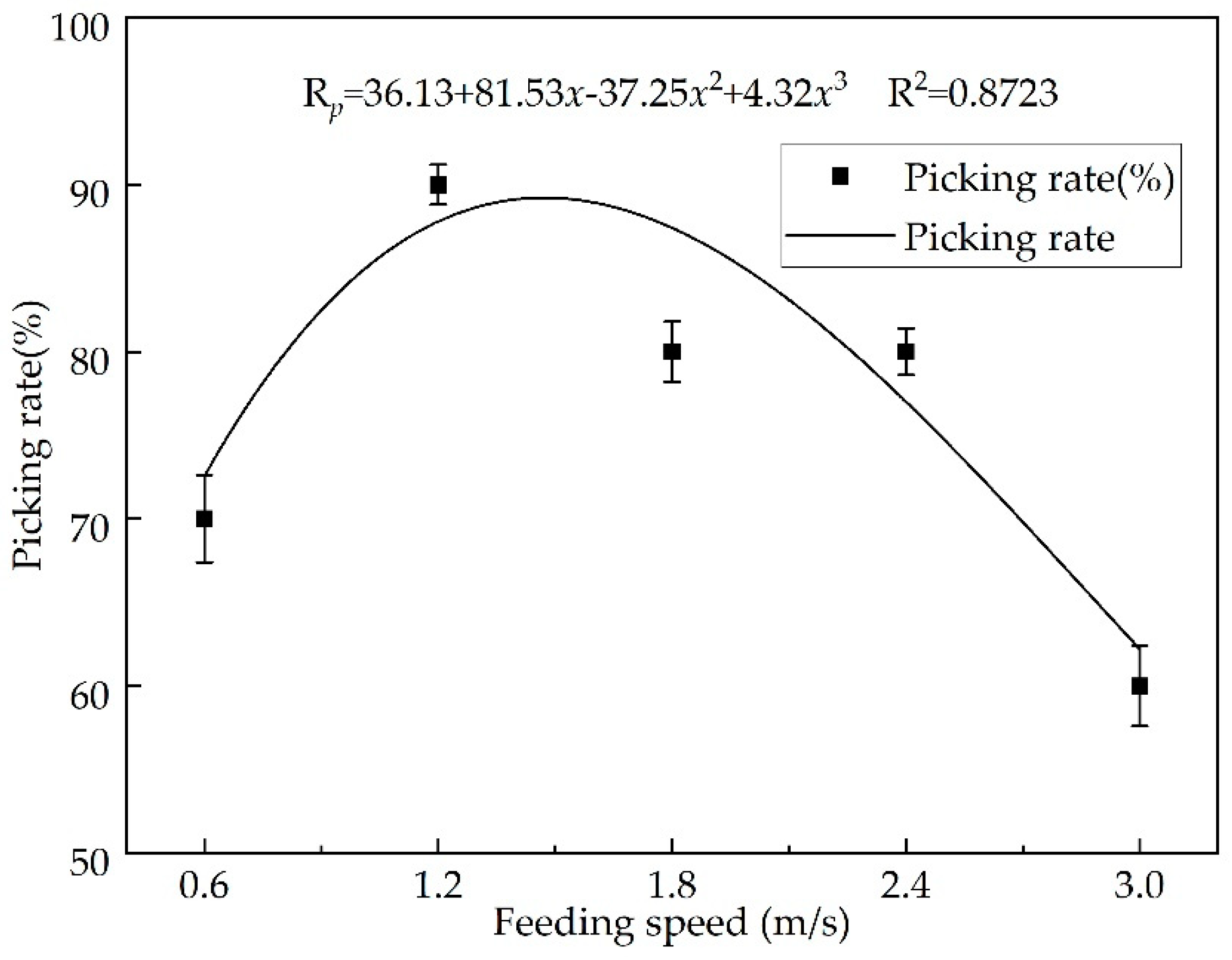
3.1.2. Stalk Feeding Speed

In the single-factor test, the whole corn plants with the roots were placed on the feeding device for camping and feeding. From the test results in Figure 11, the stalk feeding speed during header operation was adjusted by changing the movement speed of the feeding device from 0.6 m/s to 3.0 m/s. When the stalk feeding speed was too low, it was difficult to adapt the stalk feeding to the clamping device at 400 rpm, resulting in a low picking rate of 70%. The maximum picking rate of 90% was achieved when the stalk feeding speed was at 1.2 m/s. As the stalk feeding rate increased, the amount of stalk fed into the clamping and picking device increased, causing blockages. Excessive and clogged stalks were difficult to form an orderly flow of material to be clamped, so the picking rate kept decreasing. Since the stalk feeding process did not involve ear collision, the kernel loss rate was 0 at all stalk feeding speeds.

3.2. Analysis of Box Behnken Test Results

3.2.1. Test Results and Variance Analysis

The scheme and results of the Box−Behnken test are shown in Table 4. By importing the test results into Design-Expert software for statistical analysis, the quadratic regression equations of the clamping−picking device speed A, stalk feeding speed B and cutter position C were obtained. The significance of the coefficients in the regression equation was analyzed by ANOVA, and the results are shown in Table 5. In the results of ANOVA, a p-value less than 0.05 indicated a significant effect. The ANOVA of the regression model showed that the p-value was less than 0.05, indicating that the regression model of picking rate was significant. The R2 and adjusted R2 of the regression model were 0.9685 and 0.9117, respectively, indicating that the model was able to represent 91.17% of the response surface variation, and only 8.83% could not be explained using the model. The p-value of the lack of fit was greater than 0.05, indicating a good fit of the regression model.
As seen in Table 5, the p-values for the primary terms A, B and C, the interaction terms AC and BC, and the secondary terms A2, B2 and C2 of the regression model were all less than 0.05, indicating a highly significant effect on the picking rate R. Among them, the cutter position C in the primary terms was the most significant influence factor with an F-value of 21.62. The p-value for the interaction term AB was greater than 0.05 and was not significant for the picking rate R. After excluding the insignificant term, the final regression model for the picking rate was obtained as:
R = 446.02 + 2.55 A + 10.8 B + 2.52 C 0.01 A C + 0.69 B C 0.003 A 2 8.23 B 2 0.08 C 2

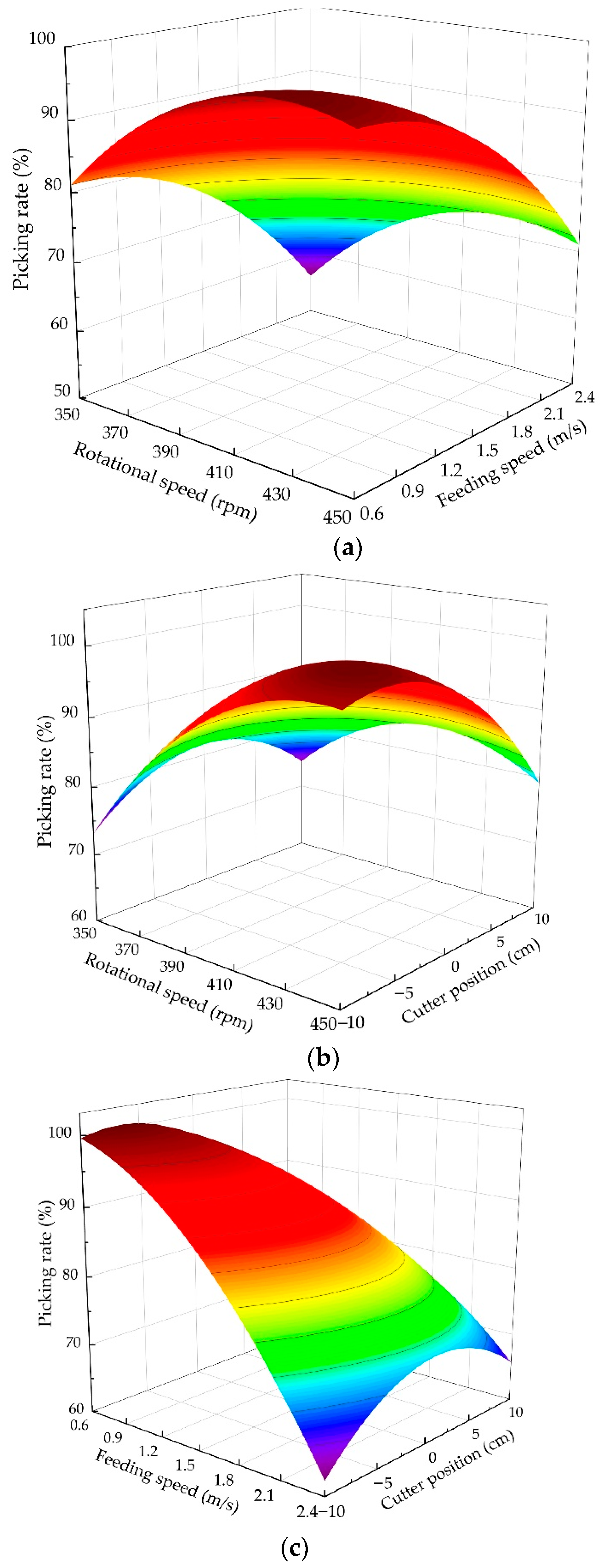
3.2.2. Response Surface Analysis

In order to investigate the effects of the interaction of clamping-picking device speed, stalk feeding speed and cutter position on the picking rate, RSM was used to generate response surface plots based on the Box−Behnken test, as shown in Figure 12.
As seen in Figure 12a, the picking rate of the bionic header increased and then decreased as the clamping-picking device speed increased and continued to decrease as the stalk feeding speed increased. When the rotational speed of the clamping-picking device was around 410 rpm and the stalk feeding speed was around 0.9 m/s, the picking rate reached its maximum value with the interaction of two factors. When the rotational speed was the minimum and the feeding speed was the maximum, the picking rate was the lowest.
In Figure 12b, with the increase of the clamping-picking device speed, the picking rate of the bionic header firstly increased and then decreased. With the position of the cutter relative to the feed inlet from front to rear, a similar trend in picking rate was observed. When the rotational speed was at 430 rpm and the cutter was located 5 cm in front of the feed inlet, the picking rate reached the maximum. At the minimum rotational speed, the lowest picking rate was achieved regardless of whether the cutter was at the front (+10 mm) or the rear (−10 mm) of the feed inlet.
It can be seen from Figure 12c that the interaction of stalk feeding speed and cutter position had an extremely significant effect on the picking rate. The picking rate of the bionic header continued to decrease with increasing stalk feeding speed. It increased and then decreased as the cutter position was moved from front to rear and reached a maximum at the position directly below the feed inlet. When the stalk feeding speed was at a minimum and the cutter was at the forefront of the feed inlet, the picking rate reached its maximum by the interaction of the two factors.

3.3. Parameter Optimization and Verification

According to the results of single-factor test and Box-Behnken test, the rotational speed of the clamping-picking device was set from 350 to 450 rpm, the range of stalk feeding speed from 0.6 to 2.4 m/s, and the position of cutter from −10 to 10 mm. The regression model in Equation (14) was imported into Design-Expert software, and the optimal combination of parameters was calculated with the maximum picking rate as the optimization objective. The optimal parameter combination and predicted picking rate are shown in Table 6.
Verification tests were performed for the optimal parameter combination in Table 6. Due to the problems of machining and assembly accuracy, the parameters of bionic reverse picking header could not reach the exact value. Therefore, the clamping-picking device speed was taken to be 420 rpm, the stalk feeding speed was 1.1 m/s, and the cutter position was −5 cm (5 cm behind the feed inlet). With the above parameters as the boundary conditions, five ear picking tests were carried out. The test results showed an average picking rate of 90%, with a relative standard deviation of 3.22% and an absolute error of 4.43% from the theoretical prediction. The error existed because the moisture content of the corn plants decreased when they were removed from the field environment, leading to a reduction in peduncular strength and greater susceptibility to fracture during the ear picking process. Overall, the bionic reverse picking header designed in this study could realize low-loss and high-efficiency harvesting of fresh corn, and the picking rate could reach more than 90% after parameter optimization.

4. Conclusions

In this study, a bionic reverse picking method was proposed taking the morphology of mature corn ears and the hand-picking behavior as the bionic prototypes. Based on this method, a bionic reverse picking header was designed, and its key components were theoretically analyzed and calculated. After that, picking tests were conducted to analyze the effects of the clamping-picking device speed, the stalk feeding speed and the cutter position on the ear picking rate. The conclusions can be summarized as follows.
The effective length of the reeling device was related to the ear height, the ear length and the angle between the ear and the stalk, its opening angle was related to the corn planting row spacing. The effective feeding and clamping conditions of the clamping device could be calculated from the relevant parameters of the field corn plants. The spiral snapping rollers allowed the corn ears to be picked under a combined action of bending, twisting and reverse stretching.
With the increase in the clamping-picking device speed and the stalk feeding speed, the picking rate first increased and then decreased. The clamping-picking device speed, stalk feeding speed, cutter position and the interactions between these factors all had an effect on the picking rate. The interaction between feeding speed and cutter position had the most significant effect. The best picking performance of the bionic header was achieved when the clamping-picking device speed was 416.81 rpm, the stalk feeding speed was 1.13 m/s, and the cutter position was −5.45 mm. The picking rate could reach more than 90% after parameter optimization, which could realize low-loss and high-efficiency harvesting of fresh corn.
Some advantages were obtained through comparison with the traditional forward picking header. The bionic reverse picking header was more suitable for harvesting fresh corns, it can not only achieve low damage low energy consumption for ear picking, but also retain the intact corn stalks, realizing full-value corn harvest.

Author Contributions

Conceptualization, L.Z. and Q.Z.; methodology, J.Y.; software, C.L.; validation, L.Z. and X.F.; formal analysis, L.Z.; investigation, C.L.; resources, Q.Z.; data curation, C.L.; writing—original draft preparation, L.Z.; writing—review and editing, Q.Z.; visualization, J.Y.; supervision, J.Y.; project administration, Q.Z.; funding acquisition, Q.Z. All authors have read and agreed to the published version of the manuscript.

Funding

This research was funded by the National Natural Science Foundation of China (Grant No. 51375206), and Jilin Provincial Science and Technology Development Plan (Grant No.20170204015NY).

Institutional Review Board Statement

Not applicable.

Informed Consent Statement

Not applicable.

Data Availability Statement

Not applicable.

Acknowledgments

Not applicable.

Conflicts of Interest

The authors declare no conflict of interest.

References

  1. Xiang, N.; Guo, X.; Liu, F.; Li, Q.; Hu, J.; Brennan, C.S. Effect of Light- and Dark-Germination on the Phenolic Biosynthesis, Phytochemical Profiles, and Antioxidant Activities in Sweet Corn (Zea mays L.) Sprouts. Int. J. Mol. Sci. 2017, 18, 1246. [Google Scholar] [CrossRef] [Green Version]
  2. Erdal, S.; Pamukcu, M.; Savur, O.; Tezel, M. Evaluation of Developed Standard Sweet Corn(Zea mays sacharata L.) Hybrids for Fresh Yield, Yield Components and Quality Parameters. Turk. J. Field Crops 2011, 16, 153–156. [Google Scholar]
  3. Islam, M.S.; Liu, J.a.; Jiang, L.; Zhang, C.; Liang, Q. Folate content in fresh corn: Effects of harvest time, storage and cooking methods. J. Food Compos. Anal. 2021, 103, 104123. [Google Scholar] [CrossRef]
  4. Gong, K.; Chen, L.; Li, X.; Liu, K. Lignin accumulation and biosynthetic enzyme activities in relation to postharvest firmness of fresh waxy corn. J. Food Process. Preserv. 2018, 42, e13333. [Google Scholar] [CrossRef]
  5. Lu, Y.C.; Watkins, K.B.; Teasdale, J.R.; Abdul-Baki, A.A. Cover crops in sustainable food production. Food Rev. Int. 2000, 16, 121–157. [Google Scholar] [CrossRef]
  6. Berger, L.L.; Paterson, J.A.; Klopfenstein, T.J.; Britton, R.A. Effect of Harvest Date and Chemical Treatment on the Feeding Value of Corn Stalklage. J. Anim. Ence 1979, 49, 1312–1316. [Google Scholar]
  7. Li, Z.; Hong, T.; Zhao, Z.; Gu, Y.; Guo, Y.; Han, J. Fatty Acid Profiles and Nutritional Evaluation of Fresh Sweet-Waxy Corn from Three Regions of China. Foods 2022, 11, 2636. [Google Scholar] [CrossRef]
  8. Li, Z.; Hong, T.; Shen, G.; Gu, Y.; Guo, Y.; Han, J. Amino Acid Profiles and Nutritional Evaluation of Fresh Sweet-Waxy Corn from Three Different Regions of China. Nutrients 2022, 14, 3887. [Google Scholar] [CrossRef]
  9. Ketthaisong, D.; Suriharn, B.; Tangwongchai, R.; Lertrat, K. Changes in physicochemical properties of waxy corn starches after harvest, and in mechanical properties of fresh cooked kernels during storage. Food Chem. 2014, 151, 561–567. [Google Scholar] [CrossRef]
  10. Agackesen, M.N.; Oktem, A.G.; Oktem, A. Effect of harvest at different at different maturation stages on fresh ear yield and characterstics of sweet corn (Zea mays L. saccharata) genotypres. Appl. Ecol. Environ. Res. 2022, 20, 3335–3351. [Google Scholar] [CrossRef]
  11. Shin, S.; Jeong, G.-H.; Kim, J.-T.; Lee, J.-S. Effect of Planting Dates on Growth and Yield of Late-planted Sweet Corn (Zea mays L.) to Sell Fresh Ears in the Autumn. Korean J. Crop Sci. 2014, 59, 299–306. [Google Scholar] [CrossRef] [Green Version]
  12. Geng, A.; Hu, X.; Liu, J.; Mei, Z.; Zhang, Z.; Yu, W. Development and Testing of Automatic Row Alignment System for Corn Harvesters. Appl. Sci. 2022, 12, 6221. [Google Scholar] [CrossRef]
  13. Fu, Q.; Fu, J.; Chen, Z.; Cui, S.; Ren, L. Experimental study on lodged corn harvest loss of small harvesters. Int. J. Arg. Biol. Eng. 2022, 15, 123–129. [Google Scholar] [CrossRef]
  14. Wang, C.; Cao, S.-K.; Wu, C.-Z.; Wang, S.-N.; Zhao, Y.-Y. Corn Harvester Cutting Table with Adjustable Spacing. In Proceedings of the 2016 International Conference on Engineering and Advanced Technology, Hong Kong, 22–23 December 2016; pp. 236–239. [Google Scholar]
  15. OXBO. Oxbo 60 Series Corn Head. Available online: https://oxbo.com/ (accessed on 15 August 2022).
  16. Yan, H.; Wu, W.; Yin, H.; Han, F. Influence of working parameters on loss rate of vertical roll corn harvester. J. Jilin Univ. 2010, 40, 113–118. [Google Scholar]
  17. Geng, D.; Li, Y.; He, K.; Jin, C. Design and experiment on gripping delivery mechanism for Vertical-rollers type of corn harvester. Trans. Chin. Soc. Agric. Mach. 2017, 48, 130–136. [Google Scholar]
  18. Fu, Q.; Fu, J.; Chen, Z.; Han, L.; Ren, L. Effect of impact parameters and moisture content on kernel loss during corn snapping. Int. Agrophys. 2019, 33, 493–502. [Google Scholar] [CrossRef]
  19. Yang, R.; Chen, D.; Zha, X.; Pan, Z.; Shang, S. Optimization Design and Experiment of Ear-Picking and Threshing Devices of Corn Plot Kernel Harvester. Agric. Basel 2021, 11, 904. [Google Scholar] [CrossRef]
  20. Shinners, K.J.; Boettcher, G.C.; Hoffman, D.S.; Munk, J.T.; Muck, R.E.; Weimer, P.J. Single-pass harvest of corn grain and stover: Performance of three harvester configurations. Trans. ASABE 2009, 52, 51–60. [Google Scholar] [CrossRef]
  21. Zhang, Z.; Chi, R.; Du, Y.; Pan, X.; Dong, N.; Xie, B. Experiments and modeling of mechanism analysis of maize picking loss. Int. J. Arg. Biol. Eng. 2021, 14, 11–19. [Google Scholar] [CrossRef]
  22. Yactayo-Chang, J.P.; Boehlein, S.; Beiriger, R.L.; Resende, M.F.R., Jr.; Bruton, R.G.; Alborn, H.T.; Romero, M.; Tracy, W.F.; Block, A.K. The impact of post-harvest storage on sweet corn aroma. Phytochem. Lett. 2022, 52, 33–39. [Google Scholar] [CrossRef]
  23. Mehta, B.K.; Hossein, F.; Muthusamy, V.; Zunjare, R.U.; Sekhar, J.C.; Gupta, H.S. Analyzing the role of sowing and harvest time as factors for selecting super sweet (-sh2sh2) corn hybrids. Indian J. Genet. Plant Breed. 2017, 77, 348–356. [Google Scholar] [CrossRef]
  24. Mehta, B.K.; Hossain, F.; Muthusamy, V.; Zunjare, R.U.; Sekhar, J.C.; Gupta, H.S. Analysis of responses of novel double mutant (sh2sh2/su1su1) sweet corn hybrids for kernel sweetness under different sowing- and harvest-time. Indian J. Agric. Sci. 2017, 87, 1543–1548. [Google Scholar]
  25. Zhang, Z.; Chi, R.; Dong, N.; Du, Y.; Li, X.; Xie, B. Design and Testing of an Intelligent Control System for Maize Picking Harvest. Appl. Sci. 2020, 10, 8888. [Google Scholar] [CrossRef]
  26. Tai, J.; Li, H.; Du, Y.; Mao, E.; Guan, Y.; Long, X. Simulation of a maize ear picking device with a longitudinal horizontal roller based on hypermesh modeling. Inmateh-Agric. Eng. 2020, 62, 69–78. [Google Scholar] [CrossRef]
  27. Song, X.; Cao, S.; Wang, C.; Wang, H. Corn harvester cutting machine overall structure and working principle. In Proceedings of the 2017 3rd International Forum on Energgy, Environment Science and Materials (IFFSM 2017), Shenzhen, China, 25–26 November 2017; pp. 839–846. [Google Scholar]
  28. Kim, I.; Ha, J.-H.; Jeong, Y. Optimization of Extraction Conditions for Antioxidant Activity of Acer tegmentosum Using Response Surface Methodology. Appl. Sci. 2021, 11, 1134. [Google Scholar] [CrossRef]
Figure 1. Principle of hand picking. (a) bending stage; (b) bending and twisting stage; (c) final stretching stage.
Agriculture 13 00093 g001
Figure 2. Schematic diagram of the bionic reverse picking header.
Agriculture 13 00093 g002
Figure 3. Structure of bionic reverse picking header.
Agriculture 13 00093 g003
Figure 4. Geometric model of the reeling device. (a) the projection in the yoz plane; (b) the projection of the reeling device in the xoy plane.
Agriculture 13 00093 g004
Figure 5. Effective feeding conditions of clamping device.
Agriculture 13 00093 g005
Figure 6. Interaction between clamping chain and corn stalk.
Agriculture 13 00093 g006
Figure 7. Ear picking process of the picking device. (a) The initial stage of the work; (b) The second stage of the work.
Agriculture 13 00093 g007
Figure 8. Interaction between spiral snapping roller and corn ear.
Agriculture 13 00093 g008
Figure 9. Bionic reverse picking header prototype. (a) front view; (b) side view.
Agriculture 13 00093 g009
Figure 10. Results of the single-factor test of the clamping-picking device speed.
Agriculture 13 00093 g010
Figure 11. Results of the single-factor test of the stalk feeding speed.
Agriculture 13 00093 g011
Figure 12. Response surfaces for interaction between the factors. (a) clamping picking device speed and stalk feeding speed; (b) clamping picking device speed and cutter position, and (c) stalk feeding speed and cutter position.
Agriculture 13 00093 g012
Table 1. Results of the single-factor test of the clamping-picking device speed.
NumbersFactorsEvaluation Indexes
Rotational Speed (rpm)Feeding Speed (m/s)Cutter
Position (cm)
Picking Rate (%)Loss Rate (%)
12501.20400
23001.20500
33501.20800
44001.20900
54501.20700
Table 2. Results of the single-factor test of the stalk feeding speed.
NumbersFactorsEvaluation Indexes
Rotational Speed (rpm)Feeding Speed (m/s)Cutter
Position (cm)
Picking Rate (%)Loss Rate (%)
14000.60700
24001.20900
34001.80800
44002.40800
54003.00600
Table 3. Coding levels of the Box−Behnken test.
LevelsRotational Speed (rpm)Feeding Speed (m/s)Cutter Position (cm)
−13500.6−10
04001.50
14502.410
Table 4. Scheme and results of Box−Behnken test.
FactorsEvaluation Indexes
NumbersA
Rotational Speed (rpm)
B
Feeding Speed (m/s)
C
Cutter Position (cm)
Picking Rate (%)
1−1−1070
21−1075
3−11060
411070
5−10−165
610−180
710165
810160
90−1−180
1001−165
110−1160
1201170
1300080
1400085
1500085
Table 5. ANOVA of the picking rate.
Cause of
Variance
Sum of SquaresFreedomMean SquareF-Valuep-ValueSignificant
Model1087.929120.8817.070.0030*
A78.12178.1211.030.0210*
B50.00150.007.060.0451*
C153.131153.1321.620.0056*
AB6.2516.250.880.3907
AC100.001100.0014.120.0132*
BC156.251156.2522.060.0054*
A2231.411231.4132.670.0023*
B2164.101164.1023.170.0048*
C2231.411231.4132.670.0023*
Residual35.4257.08
Lack of Fit18.7536.250.750.6148
Pure Error16.6728.33
Total1123.3314
R20.9685 Adjusted R20.9117
* Significant (p < 0.05)
Table 6. Results of parameter optimization.
Rotational Speed (rpm)Feeding Speed (m/s)Cutter Position (cm)Predicted Picking Rate (%)
Optimum value416.811.13−5.4585.57
Disclaimer/Publisher’s Note: The statements, opinions and data contained in all publications are solely those of the individual author(s) and contributor(s) and not of MDPI and/or the editor(s). MDPI and/or the editor(s) disclaim responsibility for any injury to people or property resulting from any ideas, methods, instructions or products referred to in the content.

