Article

Design and Test of Stripping and Impurity Removal Device for Spring-Tooth Residual Plastic Film Collector

1
Shandong Academy of Agricultural Machinery Sciences, Jinan 250010, China
2
Huang Huai Hai Key Laboratory of Modern Agricultural Equipment, Ministry of Agriculture and Rural Affairs, Jinan 250010, China
3
School of Agricultural Engineering and Food Science, Shandong University of Technology, Zibo 255000, China
*
Author to whom correspondence should be addressed.
Agriculture 2023, 13(1), 42; https://doi.org/10.3390/agriculture13010042
Submission received: 15 November 2022 / Revised: 18 December 2022 / Accepted: 20 December 2022 / Published: 23 December 2022
(This article belongs to the Section Agricultural Technology)

Abstract

:
The residual agricultural plastic film in China is not easily recovered due to the thinness and poor mechanical properties of domestic films, and a large amount of plastic film remaining in farmland soil poses a great threat to soil quality and crop production. A spring-tooth residual plastic film collector (SRPFC) is widely used in domestic residual plastic film (RPF) recycling operations. However, there are two major problems in the current SRPFC: the low recovery rate of the residual film (RRRF) caused by the difficulty of film-stripping and the high impurity rate in the film (IRF). In this paper, a stripping and impurity removal device (SIRD) is designed to address the existing problems of SRPFC, which is mainly composed of film-stripping tooth plates (FTP), two wind-collecting hoods, and two centrifugal fans. The motion and force analysis of the RPF in the film-stripping process was carried out, and the arc FTP was determined to be used for film-stripping. The size parameters of the FTP were obtained by establishing the coordinate system to solve the differential equation. By comparing and analyzing the force of RPF in the airflow field of the test bench for suspension speed and the airflow field of the wind-collecting hood, the RPF equivalent particle was established. The discrete phase model (DPM) in Fluent software was used to simulate the movement of the RPF equivalent particle, and the calculated air volume range of the centrifugal fan was 5501.88~6829.92 m3/h. The effects of forward speed, rotating speed of film conveying chain harrow (FCCH), and rotating speed of the centrifugal fan on RRRF and IRF were studied by orthogonal rotary combination experiment. The test results showed that the best combination of machine operation parameters was when the forward speed was 5 km/h, the rotating speed of the FCCH was 235 r/min, and the rotating speed of the centrifugal fan was 1978 r/min. Under these conditions, the RRRF was 92.53%, and the IRF was 9.31%. Field experiments were carried out with the rounded parameters, and the average RRRF was 92.07%, and the average IRF was 9.56% under the parameter combination, indicating that the optimization scheme of the device was feasible.

1. Introduction

Plastic film mulching technology is widely used in agricultural production in China, and it has become the third largest agricultural production material after chemical fertilizers and pesticides [1]. Most countries use thickened weather-resistant films, which have high strength when recycled, and the recovery method is mainly rolling. However, in China, the film thickness is around 0.01 mm, which has poor mechanical properties and cannot be recovered by the roll recycling method [2]. Plastic mulch film is a polymer compound that is difficult to degrade under natural conditions, resulting in a large amount of residual plastic film (RPF) remaining on the soil surface and plow layer, blocking water and fertilizer transport, deteriorating soil structure, affecting seed germination and crop root growth, and damaging agricultural machinery components [3,4]. In order to solve the problem of RPF pollution, various types of RPF recycling equipment have been developed by scientific research institutes in China, which has solved the problem of RPF recycling to a certain extent [5]. However, there are still two major problems with the current RPF recovery equipment: one is that the difficulty in film-stripping leads to the low recovery rate of residual films (RRRF); the other is the lack of an effective mechanism to reduce the impurity rate in the film (IRF), resulting in a large number of impurities in the recovered RPF [6,7].
Effective film-stripping and the reduction of IRF are the keys to improving the performance of the Spring-tooth residual plastic film collector (SRPFC). Lyu et al. [8] designed a chain guide rail-type plastic film collector, which uses the picking up film teeth to retract into the inner ring guide during movement to complete the film-stripping.
Zheng et al. [9] designed a rotary unloading RPF recycling machine, which scrapes off the RPF from the raking teeth by rotating the de-filming scraper to achieve the purpose of de-filming. Xie et al. [10] designed an arc tooth and rolling bundle-type plastic film residue collector, and its stripping method is to stroke down the RPF by the unloading guide plate. Zhao et al. [11] designed a plastic film residue collecting and balling machine and realized three-stage film stripping through the cooperation of a pin roll, a picking mechanism, and a large and small film stripping roll.
Li [12] designed a film-picking and separating film recovery machine, which is equipped with a screen device for screening RPF and impurities. Niu et al. [13] designed the collecting and separating device for strip plastic film balers, which achieves primary cleaning by throwing out the impurities through the centrifugal force of the rotating cleaning roller and achieves secondary cleaning by turning the film surface during the process of delivering the RPF from the picking roller to the de-filming mechanism. Jiang [14] designed a follower-type RPF recycler clearing system in which the RPF is picked up by the RPF pickup conveyor chain row, and then the RPF is turned over by rolling with the differential pickup roller, and the impurities on the film surface are dropped to achieve clearing. Some useful conclusions have been drawn from the above research, but due to the characteristics of light, soft, and electrostatic adsorption of RPF, gravity or mechanical methods of film-stripping and impurity removal are prone to problems such as entanglement and blockage of mechanical mechanisms, so further in-depth optimization studies are needed.
In this paper, a new idea of “mechanical film-stripping + airflow assisted film-stripping + airflow impurity removal” is proposed, and a stripping and impurity removal device (SIRD) is designed by combining the characteristics of the SRPFC. Using theoretical analysis and numerical calculation of the discrete phase model (DPM), key components were designed; regression analysis and response surface analysis were used to obtain the optimal operating parameters of the machine and conduct experimental verification, which provides a reference for improving the mechanized RPF recycling technology.

2. Materials and Methods

2.1. Structure and Working Principles

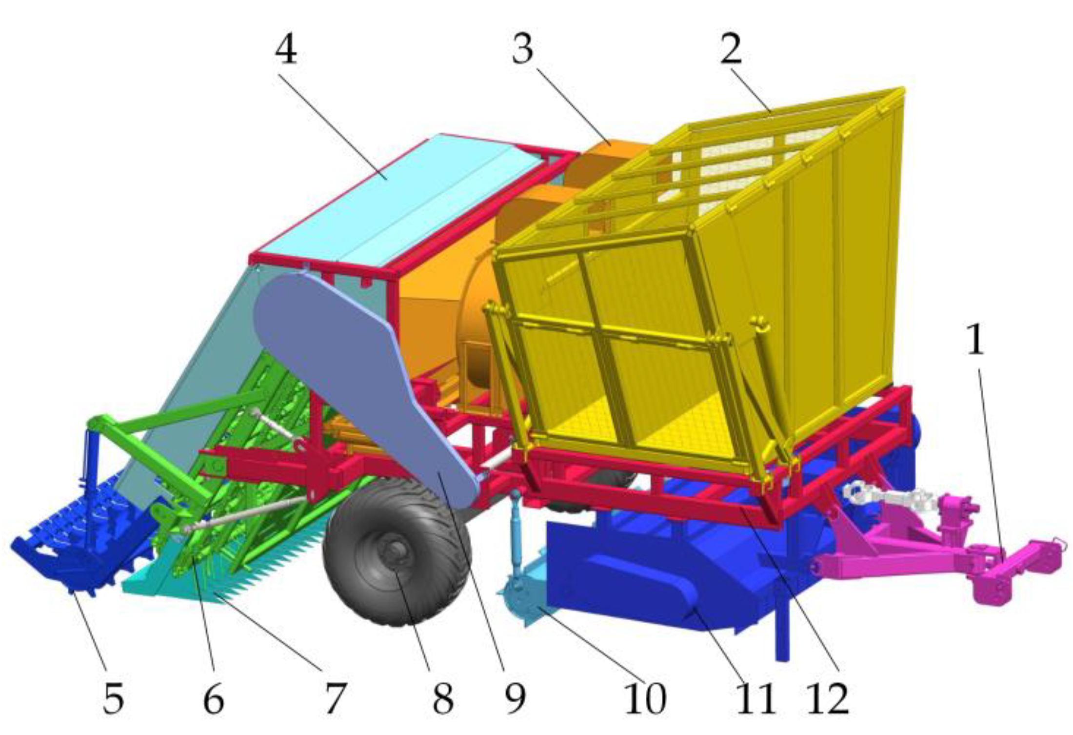
2.1.1. Machine Structure and Working Principle of the SRPFC

The structure of the RPF reclaimer is shown in Figure 1, which is mainly composed of the linkage, the collecting box, the SIRD, the cover plate, the film conveying chain harrow (FCCH), the film lifting device, the traveling system, the film cutting device, the straw crushing, and returning device, etc. During operation, the power of the tractor is input through the universal joint drive shaft, the straw crushing and returning device breaks and scatters the straw to one side of the machine, the film cutting device cuts the mulch film into small pieces, and then the film lifting device scoops up the mulch film and lifts it to a certain height. At this time, the spring teeth on the FCCH pick up the RPF and transport it upwards. The RPF is removed from the spring teeth by the SIRD and sucked into the film-collecting box.

2.1.2. Machine Structure and Working Principle of the SIRD

The structure of the SIRD is shown in Figure 2, which is mainly composed of the supporting beam, film-stripping tooth plate (FTP), the mounting plate of FTP, the wind-collecting hood, centrifugal fan, and film conveying pipe. Two fans are arranged in parallel, and the two film conveying pipes correspond to the two film conveying inlets on one side of the film collecting box, respectively.
During operation, when the FCCH transports the RPF upward along the v1 direction to the airflow field area generated by the centrifugal fan, the RPF tends to be separated from the spring teeth under the action of the drag force of the v2 direction airflow. The closer the RPF is to the wind-collecting hood, the stronger the air drag force is. With the rotation of the FCCH, the RPF is scraped off from the spring teeth by the FTP with the assistance of the air drag force. On account of the different movement paths of RPF and impurities such as straw and soil particles in the same airflow field, the RPF is transported to the film collecting box by a centrifugal fan, while the impurities fall to the impurity conveying mechanism, which is transported back to the field by the conveying mechanism.

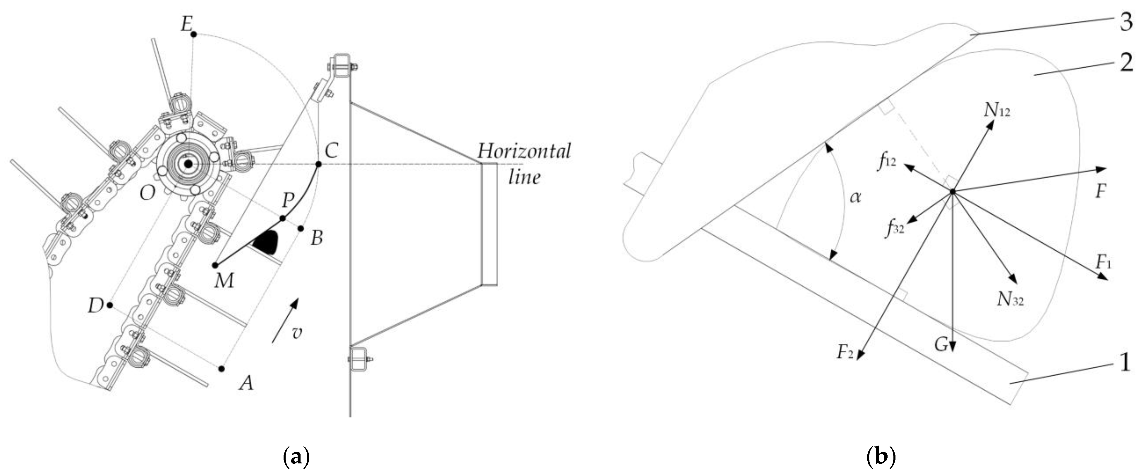
2.2. Analysis of the Film-Stripping Process and Shape Design of the FTP

2.2.1. Stress Analysis of RPF during the Film-Stripping Process

As shown in Figure 3a, in the illustrated ODABE area, the spring teeth move linearly in the direction of the chain in the AB segment and rotate counterclockwise around the O point in the BCE segment, where the B point is the dividing point. During the film-stripping process, the RPF falls off along the arc of the FTP to point C with the movement of the spring teeth.
Taking the spring teeth as a reference, the material moves toward the end of the spring teeth. The force analysis of the RPF during the film-stripping process is shown in Figure 3b. Since the aerodynamic drag force F is only related to the position of the RPF in the airflow field, and gravity G is a constant, the two forces cannot be realized by changing the structure. Therefore, the other forces except for the drag force and gravity are decomposed and synthesized into the force F1 parallel to the spring tooth and the force F2 perpendicular to the spring tooth. F1 is one of the main forces promoting the shedding of RPF. The greater the F1 value, the better the film removal. The mechanical equation is established:
{ N 12 μ 1 = f 12 N 32 μ 3 = f 32 N 32 sin α f 12 f 32 cos α = F 1 N 32 cos α N 12 f 32 sin α = F 2
where N12 is the supporting force of the spring teeth on the RPF, N; f12 is the friction force of the spring teeth on the RPF, N; μ1 is the dynamic friction factor between the spring teeth and the RPF; N32 is the FTP on the RPF The supporting force of the film, N; f32 is the friction force between the FTP and the RPF, N; μ2 is the dynamic friction factor between the FTP and the RPF; α is the angle between the spring teeth and the FTP, (°); F1 is the force directed along the spring teeth, N; F2 is the force directed perpendicular to the spring teeth, N.
When the spring tooth is located at any position, it can be obtained from formula (1) that when the size of N12 and N32 is constant, f12 and f32 are also fixed values. Increasing the α angle causes F1 to grow larger and the RPF to fall off more easily. For the traditional straight film-stripping tooth, the α angle will decrease with the movement of the spring tooth, which is not conducive to film-stripping. Therefore, the part of the FTP in the OBC area is designed as an arc to ensure that the α angle remains unchanged during the film-stripping process.

2.2.2. Solution of FTP Line

The coordinate system shown in Figure 4 is established by taking the line where the OC connection line in Figure 3a is located as the x-axis, the point O as the origin, and the line passing through point O and perpendicular to the OC as the y-axis.
Point O is the center point of the rotation of the spring tooth, and arc BC is the trajectory of the end position of the spring tooth. Suppose PC is the FTP arc line, take any point on the arc BC to connect with the O point, and the intersection point N (x0, y0) of the obtained line segment and PC is the corresponding RPF position. The angle α between the tangent line of any N point on the curve PC and the straight line ON is kept unchanged. According to the included angle formula, there is:
c = | y 0 x 0 y 0 1 + y 0 x 0 y 0 |
Solve the differential equation to get
arctan y 0 x 0 c 2 ln ( 1 + y 0 2 x 0 2 ) = c ln x 0 + a
In the above, c is the tangent value of the included angle; a is a constant.
Point B (x2, y2) and point C (x3, y3) are the tooth tip coordinates of the two positions of the spring teeth. Considering factors such as the thickness of the mulching film and the matching size of the spring teeth with the film lifting device, the straight-line distance between the set point P (x1, y1) and the point B is 70 mm, and the coordinates of the point P can be obtained. Bringing the coordinates of P and C into the formula (3), c is 3.24, a is −18.82, and the α angle is 72.85°. That is, the equation of PC of the curve part of the FTP is obtained. Since the spring teeth in the front part of the film-stripping process move in a straight line, the straight-line part PM of the FTP is the line segment that passes through point P and is tangent to the arc PC. Utilize the drawing approach to acquire the overall dimensions needed to process the FTP in accordance with formula (3).

2.3. Analysis of the Impurity Removal Process and Numerical Calculation of the DPM

2.3.1. Force and Motion Analysis of RPF in the Impurity Removal Area

The airflow field generated by the centrifugal fan first assists the FTP in film-stripping before separating the impurities and RPF. The effect of the removal and impurity removal is directly influenced by the airflow velocity of the airflow field. The high airflow speed makes it easy to remove the film, but if the airflow is too high, the impurity removal effect will be reduced.
As shown in Figure 5, the RPF falls off at the O2 point and enters the impurity-removing area. In order to separate the RPF from impurities and ensure that the RPF is recovered, the conditions are as follows: The RPF must pass the boundary of the impurity-removing area above point B, and impurities fall onto the air-collecting hood plate and then slide or directly fall onto the impurity conveying mechanism.
During operation, the RPF in the impurity-removing area is mainly subject to the air drag force F, gravity G, and the buoyancy of the RPF in the air. The density of the RPF is much larger than that of air, so the buoyancy of the RPF in the air is negligible [15].
The RPF is subjected to air drag force F as follows [16,17,18]:
F = 1 2 C ρ f A V 2
where C is the resistance coefficient; ρf is the air density, kg/m3; A is the wind-receiving area of the RPF, m2; V is the relative velocity of the RPF and the airflow, m/s.
The formula for calculating gravity is:
G = m g
In the formula, m is the mass of the RPF, kg; g is the acceleration of gravity, m/s.
According to the force balance relationship, the kinetic equation of the RPF in the impurity-removing area is obtained as follows:
m a = m d v d t = F + G
In the above, a is the RPF acceleration, m/s2; v is the RPF velocity, m/s.
As shown in Figure 5, the XO2Y coordinate system is established when the RPF is separated from the spring teeth:
{ v x 0 = 0 v y 0 = ω L 0
In the above: vx0 is the horizontal velocity of the RPF at the O2 point, m/s; vy0 is the vertical velocity of the RPF at the O2 point, m/s; ω is the rotating speed of the FCCH, rad/s; L0 is the distance between O1 point and O2 point, m.
L0 is 0.33 m. According to the previous research basis, the rotating speed of the FCCH is preliminarily set to 220~260 r/min, the vertical speed vy0 is 1.21~1.43 m/s, and the direction is the negative direction of the y-axis.

2.3.2. Equivalent Simplified Model Building

It is challenging to accurately calculate the motion of the RPF in the airflow field using conventional methods because of the wide variation in individual shapes and the high flexibility of the RPF materials. In this paper, the equivalent method is used to analyze the motion of the RPF in the airflow field; that is, the RPF is equivalent to a spherical particle with the same trajectory. With the help of Fluent finite element software, a DPM is established, and the air velocity range at the suction port of the centrifugal fan is clarified by changing the parameters of the airflow field for simulation.
The motion trajectory of the RPF in the airflow field is mainly affected by the acceleration generated by gravity and aerodynamic drag force. Since the gravitational acceleration is constant, only the equivalent analysis is performed for the airflow drag acceleration it receives.
The acceleration generated by the aerodynamic drag force can be obtained by formula (4):
a = C ρ f A V 2 2 m
The flexible RPF has a different area from the windward of the actual area in the airflow field. To simplify the solution, it is assumed that the windward area of the same RPF remains unchanged under different wind speeds, and the deformation coefficient b is introduced. Make the accelerations before and after the equivalence equal, as follows:
a = C ρ f A 1 b V 2 2 m 1 = C ρ f A 2 V 2 2 m 2
In the formula, A1 is the actual area of the RPF, m2; A2 is the windward area of the equivalent sphere, m2; m1 is the mass of the RPF, kg; and m2 is the equivalent sphere mass, kg.
Available after sorting:
A 1 b m 1 = A 2 m 2
After substituting the area and mass formulas into the arrangement, we can get the following:
d = 3 δ ρ s 1 2 ρ s 2 b
In the formula, d is the diameter of the equivalent sphere, m; ρs1 is the density of the RPF, kg/m3; ρs2 is the density of the equivalent sphere, and kg/m3; δ is the thickness of the RPF, m.
In the airflow field of the test bench for suspension speed, the RPF is mainly subjected to aerodynamic drag force, gravity, and buoyancy of the RPF in the air, which is the same as the force of the RPF in the air field of the SIRD. Ignoring the buoyancy of the RPF in the air, in equilibrium, the vertical downward gravity of the RPF is equal to the vertical upward airflow drag [19,20]:
m 1 g = 1 2 C 0 ρ f A 1 b v L 2
In the formula, C0 is the resistance coefficient of the airflow field of the test bench; vL is the suspension velocity, m/s.
Available after sorting:
b = 2 δ ρ s 1 g C 0 ρ f v L 2
After putting it into Equation (11), the following formula can be obtained:
d = 3 C 0 ρ f v L 2 4 g ρ s 2
Samples were collected at the machine cotton picking base of Jingguo Agricultural Machinery Professional Cooperative in Wudi, Binzhou, and the RPF with an area of 0.02~0.07 m2 was manually cut as the test material. The suspension velocity was measured by the PS-20 test bench for suspension speed (Jiamusi Tiansheng Machinery Technology Development Co., Ltd.). The change in the shape of the RPF in the airflow field of the wind-collecting hood causes a change in the windward area, which will lead to a deviation between the simulation results and the actual results. In order to improve the accuracy of the results, in addition to testing the RPF with different area sizes, it is also necessary to test the suspension speed of the same RPF with various shape states. The measured suspension velocity vL of the RPF is 1.6~2.8 m/s. According to Equations (9) and (13), when the suspension velocity vL is high, the acceleration generated by the same airflow is low, and the required airflow velocity is relatively high. Therefore, the upper limit of the suspension velocity vL is 2.8 m/s, which can theoretically avoid the phenomenon of RPF leakage.
The value of C0 depends on the size of the Reynolds number Re [21,22]:
R e = ρ f v L L μ
where vL is the air velocity, m/s; L is the characteristic length, m; and μ is the dynamic viscosity, Pa·s.
Since the air density is 1.25 kg/m3 and the dynamic viscosity is 1.8 × 10⁻⁵ Pa·s. The characteristic length is 0.3 m, which is determined by the test bench’s diameter. From the formula (15), it is known that Re is in the range of 103~2 × 10⁵, The flow state of the fluid is turbulent, and the C0 value is 0.44 [23].
The mulch film is made of low-density polyethylene, which has a density of 910–925 kg/m3, in accordance with the national standard GB13735–92 of “Polyethylene Blown Mulch Film for Agricultural Uses.” ρs2 is taken as 910 kg/m3, and d is calculated to be 0.362 mm.

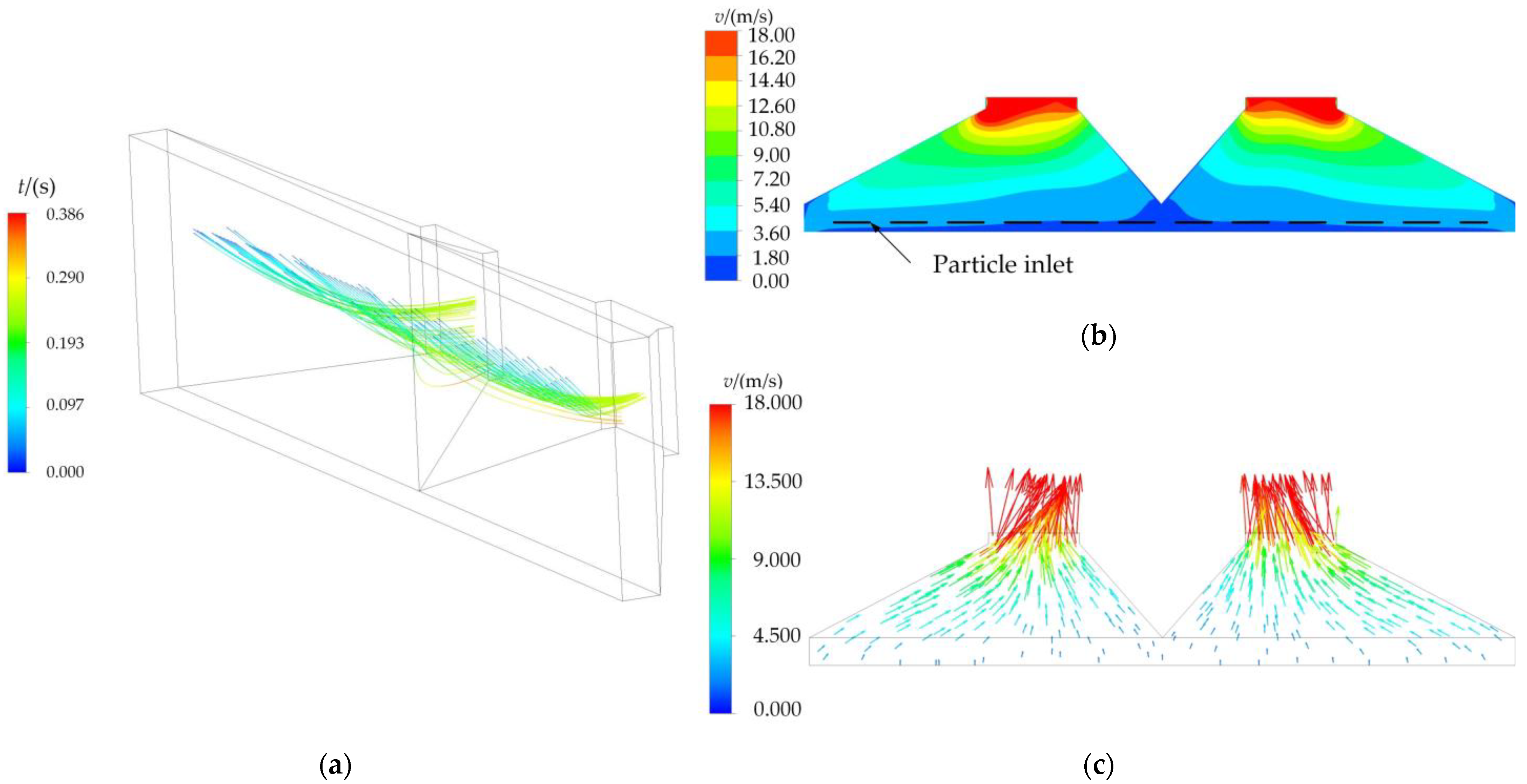
2.3.3. Numerical Computation of DPM

On the basis of the motion analysis results of the RPF in the impurity-removing area, the internal area of the wind-collecting hood and the outward extension part of the inlet of the wind-collecting hood are selected to form the fluid domain of the wind-collecting hood, as shown in Figure 6. The position of the outlet is set as the velocity outlet of the flow field, and the air flows out of the fluid domain at a constant speed; the air can freely enter and exit from the five surfaces of the fluid domain outside the collecting hood; the particle inlet is in the fluid domain outside the collecting hood.
Due to the regular shape of the fluid domain, the airflow direction is consistent with the grid direction, so the hexahedral grid method can reduce the calculation amount while ensuring accuracy. Based on the hexahedral mesh method, the Mesh module in ANSYS is used to mesh the model. The number of meshes is 1,290,240. The maximum skewness of the mesh quality is 0.6946, and the average is 0.3016, which indicates that the mesh quality is acceptable. The model mesh is shown in Figure 7 [24].
The standard k-ε model and the standard wall function method are used to calculate the flow field, and the DPM is used to calculate the particle motion. The dichotomy selects different wind speeds to set the outlet and then runs the calculation program. The RPF equivalent particles are inserted at the particle inlet once the calculation is finished for verification. The above process is repeated until the particles can pass through the fluid domain without touching the lower side plate of the wind-collecting hood, at which time the outlet wind speed is the minimum wind speed.
The velocity range of the RPF is obtained by the formula (7). The initial vertical velocity vy0 of the particles ranges from 0 to 1.43 m/s, and the initial horizontal velocity is 0 m/s.
When the vertical velocity vy0 of the particles is 1.43 m/s, the particles should pass through the fluid domain without touching the lower side plate of the wind-collecting hood, and the air velocity at the outlet should be at least 14.5 m/s. The particle trajectory is shown in Figure 8a, so the lower limit of wind speed is 14.5 m/s. It may be determined that there is air-assisted film-stripping at the particle inlet by selecting the middle horizontal section of the fluid domain as the study object and analyzing the velocity distribution of the airflow field, as shown in Figure 8b,c [25].
The upper limit of wind speed is computed with the vertical particle velocity set to 0 m/s. When the wind speed at the outlet is 18 m/s, the particles can pass through the fluid domain without touching the lower side plate of the wind-collecting hood, and the particle running trajectory is shown in Figure 9a. The middle horizontal section of the fluid domain is selected as the object of research to analyze the velocity distribution of the airflow field and Figure 9b,c are obtained. By comparing Figure 8 with Figure 9, it is evident that the larger the outlet air velocity is, the larger the airflow velocity in the de-filming area is, and the easier the RPF is to fall off from the spring teeth.
Based on the above analysis, the wind speed range of the outlet is 14.5 ~ 18 m/s. The air volume of the outlet, which is the air volume of the centrifugal fan, is calculated based on the wind speed:
Q = V f × S × 3600
where Q is the air volume of the centrifugal fan, m3/h; Vf is the air velocity of the outlet, m/s; and S is the area of the outlet, m2.
The required centrifugal fan air volume range is 5501.88~6829.92 m3/h, and then the rotating speed of the centrifugal fan is calculated according to the selected centrifugal fan model, which provides a theoretical basis for the test.

2.4. Materials and Methods of Field Experiment

2.4.1. Test Conditions

In November 2021, the field performance test of the spring-tooth RPF collector was carried out in the cotton-picking base of Wudi Jingguo Agricultural Machinery Cooperative in Binzhou, Shandong. The test land area is 1.0 hm2, with a level topography and wide row film mulching planting mode. The mulch film thickness is 0.01 mm, and the drip irrigation belt has been pulled out. The experimental equipment was as follows: HSTL-TRCS02-3 portable soil moisture meter (Huakong Industrial, accuracy ±3%), hand-held thermal anemometer (wind speed measurement range: 0~30 m/s, wind speed measurement error: ±1%), UT372 high-precision non-contact tachometer (measurement range: 0~99999 r/min, speed measurement accuracy 0.04% ± 2), stopwatch (measurement accuracy: 0.01 s), tape measure (measurement accuracy: 1 mm), electronic scale (measurement accuracy: 10 g), shovel, etc.

2.4.2. Test Method

The field operation performance test of the stripping and impurity removal device is conducted according to the test method specified in the Chinese national standard GB/T 25412-2010 Mulch Film Residue Collector, as shown in Figure 10. The RRRF and the IRF were selected as evaluation indicators.
First, the RPF in the test field was mechanically collected, and then it was manually retrieved. The mass of the RPF picked up manually is measured as m0, and the mass of the film impurity mixture in the collection box is m1. Next, impurities were removed (straw, small clods, etc.) from the RPF, and its mass, m2, was measured. The calculation formula of the RRRF Y1 and the IRF Y2 is as follows:
Y 1 = m 2 m 0 + m 2 × 100 %
Y 2 = m 2 m 1 × 100 %

2.4.3. Experimental Design

According to formula (7), it is apparent that the rotating speed of the FCCH determines the material’s initial speed as it departs the spring teeth; at the same time, in order to prevent the RPF from being missed by the spring teeth, there is a cooperative relationship between the forward speed and the rotating speed of the FCCH; the rotating speed of the centrifugal fan determines the airflow field air velocity; airflow velocity affects the trajectory of RPF material. Therefore, the forward speed, the rotating speed of the FCCH, and the rotating speed of the fan have an impact on the RRRF and IRF. These three factors are selected as the test factors. Through the automatic driving system, the forward speed of the tractor can be accurately adjusted; replace the sprocket and pulley to adjust the rotating speed of the FCCH and the rotating speed of the centrifugal fan, respectively.
According to the previous design and analysis, comprehensively weigh the actual requirements of the RPF recovery operation, select the forward speed X1 (4~6 km/h), the rotating speed of the FCCH X2 (220~260 r/min), and the rotating speed of the centrifugal fan X3 (1800~2100 r/min) as the test factors, and the RRRF Y1 and the IRF Y2 are used as the performance evaluation indicators of the SRPFC.
In accordance with the principle of Box-Behnken experimental design, the experimental factors and the range of values are shown in Table 1. A total of 17 groups of experiments are implemented, as shown in Table 2(X1, X2, and X3 are factor coding values in the table). Three times each test group was administered, with the average of the three results taken as the final test result. The data processing analysis was performed by Design-Expert 10.0.3 software [26,27].
The test results are shown in Table 2. The RRRF after the operation of SRPFC is 85.34% to 93.36%, and the IRF is 8.67 to 13.95%. The operation effect meets the operational requirements of GB/T 25412-2010 “Mulch Film Residue Collector”.

3. Results and Discussion

3.1. Results

The analysis module of the Design-Expert 10.0.3 software was utilized to process the experimental results. Table 3 shows the results of the regression variance analysis.
The p-values of the RRRF and the IRF were 0.2104 and 0.2729, respectively, indicating that the lack of fit was not significant, the fitting accuracy was excellent, and the regression was effective. Therefore, the RRRF and IRF can be examined and predicted using this model. According to the analysis results of Table 3, multiple regression fitting was carried out [28,29]. After the insignificant items were eliminated, the regression equation of the influence of each factor on the RRRF Y1 and the IRF Y2 was obtained as follows:
Y 1 = 92.53 0.61 X 1 + 0.42 X 2 + 1.09 X 3 2.01 X 1 X 2 + 0.5 X 1 X 3 2.48 X 1 2 1.87 X 2 2
Y 2 = 9.5 0.073 X 1 + 1.15 X 2 0.075 X 3 + 0.17 X 1 X 2 + 0.31 X 1 X 3 + 0.64 X 2 2 + 2.07 X 3 2
From the analysis in Table 3 and the p-value of each factor, it can be seen that the influence of each factor on the RRRF is from large to small: forward speed, rotating speed of the FCCH, and the rotating speed of the centrifugal fan. The influences of each factor on the IRF is from large to small: the rotating speed of the centrifugal fan, the rotating speed of the FCCH, and the forward speed.

3.2. Discussion

The influences of interaction factors on the evaluation index were fixed at the intermediate level, and the interaction influences of the other two factors on the evaluation index were analyzed. The influences of forward speed, rotating speed of the FCCH, and rotating speed of the centrifugal fan on the evaluation index were analyzed using a response surface diagram and contour map.
(1)
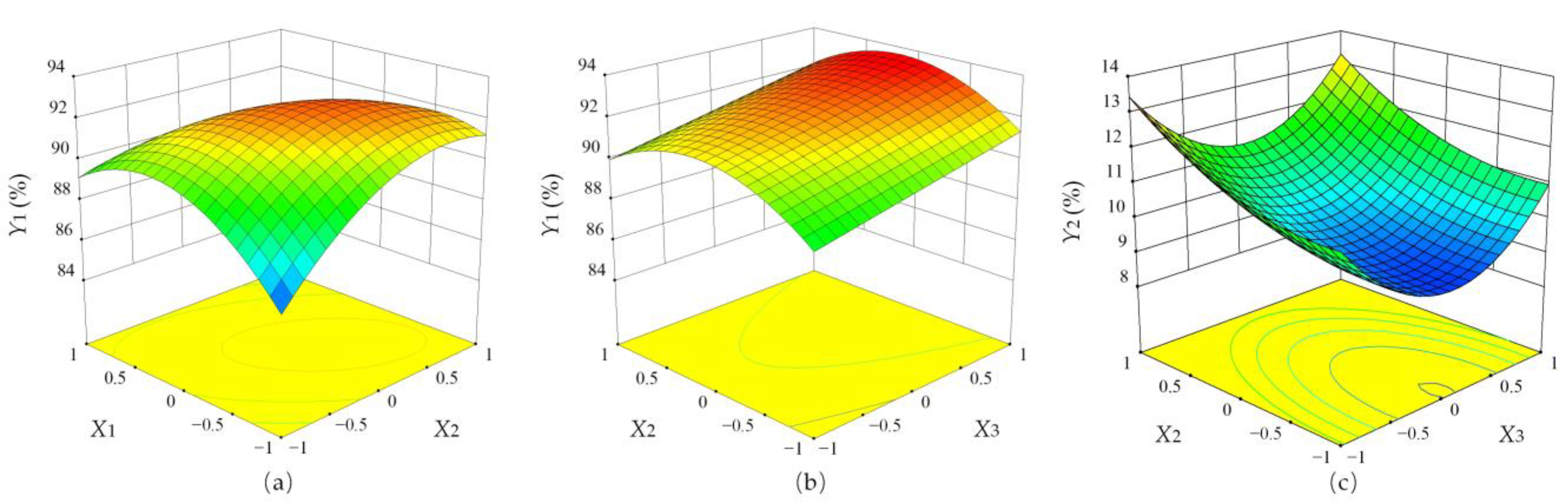
Analysis of the effect of factor interaction on the RRRF
It can be seen from Figure 11a as the forward speed and rotating speed of the FCCH increase under the combined influence of the two parameters, the RRRF initially increases and subsequently drops. The change of the response surface curve of the RRRF is obvious along the direction of the forward speed, which indicates that the effect of the forward speed on the RRRF is more significant than that of the rotating speed of the FCCH. In order to prevent the RPF from being missed by the spring teeth, the forward speed and the rotating speed of the FCCH need to meet certain matching conditions. Therefore, the main reasons are analyzed as follows: When the forward speed and the rotating speed of the FCCH are both at a low level, the low rotating speed of the FCCH causes some of the RPF to fall off in the film-stripping area before reaching the film-stripping position, which causes insufficient recovery, resulting in a low RRRF; when the forward speed and the rotating speed of the FCCH are at a high level, the main reason for the decrease in the RRRF is that the increase in the vibration of the machine causes some RPF to fall off in advance and the insufficient film-stripping of FTP caused by the high rotating speed of FCCH.
It can be seen from Figure 11b that under the interaction of the two factors, the RRRF first increases and then decreases with the increase of the rotating speed of the FCCH, and the RRRF increases with the increase of the rotating speed of the centrifugal fan. The response surface curve of RRRF changed obviously along the direction of the rotating speed of the FCCH, which indicated that the effect of the rotating speed of the FCCH on RRRF was more significant than that of the rotating speed of the centrifugal fan. The primary reason is that with the increase of the rotating speed of the centrifugal fan, the negative pressure intensity generated by the fan increases, making it simpler to remove RPF from the spring teeth and improve the RRRF.
(2)
Analysis of the effect of factor interaction on IRF
It can be seen from Figure 11c that under the interaction of the two factors, the IRF increases with the increase of the rotating speed of the FCCH; the IRF decreases first and then increases with the increase of the fan rotational speed. The response surface curve of RPF impurity content changes obviously along the direction of the rotating speed of the centrifugal fan, which indicates that the effect of the rotating speed of the centrifugal fan on IRF is more significant than that of the rotating speed of the FCCH. The main reason is that with the increase in the rotating speed of the FCCH, the number of materials transported per unit of time increases, the interaction between materials makes the impurity removal effect worse, and the IRF increases.
When the rotating speed of the centrifugal fan is low, the wind speed of the airflow field is enhanced with the increase of the rotating speed of the centrifugal fan, and the difference between the trajectory of the RPF and the impurity in the airflow field is more obvious, resulting in a good separation effect and low impurity content. When the rotational speed is at a high level, with the increase of wind speed, more and more impurities will be inhaled by the fan, and the wind separation effect will be weakened, resulting in an increase in impurity content.

3.3. Optimization of Operation Parameters and Test Verification

To achieve optimum performance of the prototype, the Design-Expert was used to solve the multi-objective optimization of the RRRF and the IRF [30,31]. The upper and lower limits of each test factor are set as constrained optimization intervals. The maximum RRRF and the minimum IRF are set as the optimization objectives of the test index, and the optimization objective is equal weight (+ + +). The optimization results were: forward speed of 5 km/h, rotating speed of the FCCH of 235 r/min, and rotating speed of the centrifugal fan of 1978 r/min. Under these conditions, the RRRF was 92.53%, and the IRF was 9.31%.
In order to verify the feasibility of the optimization results, experiments were carried out according to the predicted values, and the RRRF and the IRF were calculated according to formulas (17) and (18) [32,33]. Considering the feasibility of the test, the operation parameters were rounded and optimized, and the test was repeated three times with the forward speed of 5 km/h, rotating speed of the FCCH of 235 r/min, and rotating speed of the centrifugal fan of 1980 r/min, and the average value was taken as the test result (see Table 4).

4. Conclusions

(1)
Through the force analysis of the RPF in the process of film-stripping, it is determined to use the FTP for film-stripping, and the corresponding arc calculation formula is obtained. The drawing method was used to obtain the external dimensions in accordance with the formula, and then the FTP was processed. According to the analysis results of the movement and force of the RPF in the airflow field, an equivalent simplified sphere model of the RPF is established. By using the DPM method in Fluent software to numerically simulate the motion of the equivalent simplified spherical model in the fluid domain, it is clear that the required air volume range of the centrifugal fan is 5501.88~6829.92 m3/h;
(2)
Combined with the design principle of the Box Behnken experiment, the RPF recovery performance of the SRPFC was tested. The experiment was carried out by the orthogonal rotation combination of multiple factors. Through response surface analysis, the factors that affected the RRRF were, in the order of large to small: forward speed, rotating speed of the FCCH, and rotating speed of the fan; the factors affecting the IRF, from large to small, were: speed of the fan, speed of film conveying chain rake, and forward speed;
(3)
The Design-Expert software was used to optimize the regression equation, and the best working parameters of the SRPFC were obtained as follows: forward speed of 5 km/h, rotating speed of the FCCH of 235 r/min, and rotating speed of the centrifugal fan of 1978 r/min. Field tests were carried out with the parameters after rounding, and it was shown that the average RRRF was 92.07% and the average IRF was 9.56% under these parameters. The test results of the whole machine are good, and all the operation indexes meet the requirements of Chinese national and industry standards.

Author Contributions

Conceptualization, Q.P. and X.W.; methodology, K.L. and G.Z.; software, K.L. and G.Z.; validation, Q.P. and K.L.; formal analysis, Q.P. and J.K.; investigation, J.K.; resources, J.K. and Q.P.; data curation, Q.P. and K.L.; writing—original draft preparation, K.L.; writing—review and editing, J.K. and Q.P.; visualization, X.W.; supervision, J.K.; funding acquisition, J.K. All authors have read and agreed to the published version of the manuscript.

Funding

This research was funded by the National Natural Science Foundation of China Projects (grant number 52175238).

Institutional Review Board Statement

Not applicable.

Informed Consent Statement

Not applicable.

Data Availability Statement

Not applicable.

Acknowledgments

We would like to thank all the reviewers who participated in the review. We also thank the funders of the project. All supports and assistance is sincerely appreciated.

Conflicts of Interest

The authors declare no conflict of interest.

References

  1. Yang, H. Plastic Film and Ecological Environment Protection; Chemical Industry Press: Beijing, China, 2000. [Google Scholar]
  2. Hu, R.; Liu, D.; Wang, L.; Wan, X. Application and recycling experience of agricultural film in developed countries. World Agric. 2019, 2, 89–94. [Google Scholar]
  3. Yan, C.; Liu, E.; Shu, F.; Liu, Q.; Liu, S.; He, W. Review of agricultural plastic mulching and its residual pollution and prevention measures in China. J. Agric. Resour. Environ. 2014, 31, 95–102. [Google Scholar]
  4. Xie, H.; Li, Y.; Yang, S.; Wang, J.; Wu, X.; Wu, Z. Research on the influence of farmland residual film on soil environment and crop growth and development. J. Agro Environ. Sci. 2007, S1, 153–156. [Google Scholar]
  5. Li, D.; Zhan, W.; Xin, S.; Liu, X.; Qu, H.; Xu, Y. Research status and prospect of farmland residual film recycling technology. Chin. J. Agric. Mach. 2020, 41, 204–209. [Google Scholar]
  6. Zhao, Y.; Chen, X.; Wen, H.; Zheng, X.; Niu, Q.; Kang, J. Research status and prospect of control technology for residual plastic film pollution in farmland. Trans. Chin. Soc. Agric. Mach. 2017, 48, 1–14. [Google Scholar]
  7. Zhang, H.; Kang, J.; Zhang, G.; Wang, Y.; Du, H.; Sun, H. Analysis on the current situation and countermeasures of agricultural film pollution in the Huanghuaihai region. Chin. J. Agric. Mach. 2019, 40, 156–161. [Google Scholar]
  8. Lyu, Z.; Zhang, L.; Zhang, G.; Liu, S. Design and test of chain guide rail-type plastic film collector. Trans. Chin. Soc. Agric. Eng. 2015, 31, 48–54. [Google Scholar]
  9. Zheng, S.; Cao, S.; Wang, M.; Lu, Y.; Ying, Y.; Sun, B.; Zhao, Y. Design and experiment of rotary stripping type residual film recovery machine. J. Northwest A&F. Univ. (Nat. Sci. Ed.). 2020, 48, 146–154. [Google Scholar]
  10. Xie, J.; Zhang, F.; Chen, X.; Han, Y.; Tang, W. Design and parameter optimization of curved tooth rolling type residual film recovery machine. Trans. Chin. Soc. Agric. Eng. 2019, 35, 26–37. [Google Scholar]
  11. Zhao, Y.; Zheng, X.; Chen, X.; Niu, Q.; Ji, C.; Zhou, D. CMJY-1500 type farmland residual film picking and packing joint cooperation, design and experiment of industrial machine. Trans. Chin. Soc. Agric. Eng. 2017, 33, 1–9. [Google Scholar]
  12. Li, S. Design and Research on the Key Components of the Mulching Film Recycling Machine with Mulching and Hybridization; Shihezi University: Shihezi, China, 2020. [Google Scholar]
  13. Niu, Q.; Ji, C.; Zhao, Y.; Cheng, X.; Zheng, X.; Li, H. Design and experiment on collecting and separating device for strip plastic film baler. Trans. Chin. Soc. Agric. Mach. 2017, 48, 101–107. [Google Scholar]
  14. Jiang, D. Research and Experiment on Cleaning System of Profile Modeling Residual Film Recovery Machine; Shihezi University: Shihezi, China, 2020. [Google Scholar]
  15. Peng, W. Study on the Solid Particle Erosion Mechanism of Pipe Bend for Multiphase Flow; China University of Petroleum: Qingdao, China, 2017. [Google Scholar]
  16. Guo, W.; He, X.; Wang, L.; Zhao, P.; Hu, C.; Hou, S.; Wang, X. Development of a comb tooth loosening and pneumatic stripping plough layer residual film recovery machine. Trans. Chin. Soc. Agric. Eng. 2020, 36, 1–10. [Google Scholar]
  17. Yang, X. Research on MSW Compacting Separating Technology and Corresponding Mechanical Equipment; Xi’an University of Technology: Xi’an, China, 2004. [Google Scholar]
  18. Zhang, X.; Liu, J.; Shi, Z.; Jin, W.; Yan, J.; Yu, M. Design and parameter optimization of reverse membrane and soil separation device for residual film recovery machine. Trans. Chin. Soc. Agric. Eng. 2019, 35, 46–55. [Google Scholar]
  19. Jin, W.; Zhang, X.; Ding, Y.; Bai, S.; Liu, W.; Zhou, X. Experiment on suspension separation of residual film and impurity based on EDEM-Fluent coupling. Trans. Chin. Soc. Agric. Mach. 2022, 53, 89–98. [Google Scholar]
  20. Wen, X.; Jia, H.; Zhang, S.; Yuan, H.; Wang, G.; Chen, T. Test of suspension velocity of granular fertilizer based on EDEM-Fluent coupling. Trans. Chin. Soc. Agric. Mach. 2020, 51, 69–77. [Google Scholar]
  21. Versteeg, H.; Malalasekera, W. An Introduction to Computational Fluid Dynamics—The Finite Volume Method; Prentice Hall: Upper Saddle River, NJ, USA, 2010. [Google Scholar]
  22. Cai, Z.; Long, T. Hydrodynamic Pump and Fan; China Architecture Press: Beijing, China, 2009. [Google Scholar]
  23. Ma, Y. Agricultural Materials; Chemical Industry Press: Beijing, China, 2015. [Google Scholar]
  24. Li, X. The Research of Winnowing Characteristics on Tobacco Cutting and Rebaking in the DPM Model; Kunming University of Science and Technology: Kunming, China, 2020. [Google Scholar]
  25. Yang, S. Design and Key Technology Research of Passive Cotton Field Residual Plastic Film Recycling Machine; Jilin University: Jilin, China, 2020. [Google Scholar]
  26. Dai, F.; Guo, X.; Zhao, W.; Xin, S.; Liu, X.; Wu, Z. Design and experiment of canvas belt combined operation machine for potato digging and plastic film collecting. Trans. Chin. Soc. Agric. Mach. 2018, 49, 104–113. [Google Scholar]
  27. Shi, G.; Li, J.; Ding, L.; Zhang, Z.; Ding, H.; Li, N.; Kan, Z. Calibration and Tests for the Discrete Element Simulation Parameters of Fallen Jujube Fruit. Agriculture 2022, 12, 38. [Google Scholar] [CrossRef]
  28. Horabik, J.; Wiacek, J.; Parafiniuk, P.; Banda, M.; Kobylka, R.; Stasiak, M.; Molenda, M. Calibration of discrete-element-method model parameters of bulk wheat for storage. Biosyst. Eng. 2020, 200, 298–314. [Google Scholar] [CrossRef]
  29. You, J.; Zhang, B.; Wen, H.; Kang, J.; Song, Y.; Chen, X. Design and test optimization on spade and tine combined residual plastic film device. Trans. Chin. Soc. Agric. Mach. 2017, 48, 97–104. [Google Scholar]
  30. Han, L.; Yuan, W.; Yu, J.; Jin, J.; Xie, D.; Xi, X.; Zhang, Y.; Zhang, R. Simulation and Experiment of Spiral Soil Separation Mechanism of Compound Planter Based on Discrete Element Method (DEM). Agriculture 2022, 12, 511. [Google Scholar] [CrossRef]
  31. Yan, W.; Hu, Z.; Wu, N.; Xu, H.; You, Z.; Zhou, X. Parameter optimization and experiment of film transmission mechanism of spade screen recovery machine. Trans. Chin. Soc. Agric. Eng. 2017, 33, 17–24. [Google Scholar]
  32. Wu, T.; Kong, F.; Shi, L.; Xie, Q.; Sun, Y.; Chen, C. Power Consumption Influence Test of Castor Disc-Cutting Device. Agriculture 2022, 12, 1535. [Google Scholar] [CrossRef]
  33. Hu, S.; Hu, Z.; Gu, F.; Wu, F.; Wu, P. Design on automatic un loading mechanism for teeth type residue plastic film collector. Trans. Chin. Soc. Agric. Eng. 2017, 33, 8–15. [Google Scholar]
Figure 1. Overall structure diagram of SRPFC. Note: 1—Linkage; 2—Collecting box; 3—SIRD; 4—Cover plate; 5—Crushing device; 6—FCCH; 7—Film lifting device; 8—Traveling system; 9—Transmission device; 10—Film cutting device; 11—Straw crushing and returning device; 12—Rack.
Agriculture 13 00042 g001
Figure 2. Schematic diagram of the structure of the SIRD. Note: 1—Supporting beam; 2—Mounting plate of FTP; 3—Spring teeth; 4—FCCH; 5—Supporting plate; 6—Impurity conveying mechanism; 7—FTP; 8—Wind-collecting hood; 9—Centrifugal fan; 10—Film conveying pipe.
Agriculture 13 00042 g002
Figure 3. Analysis of the movement trajectory of the spring teeth and the force analysis of the RPF in the film-stripping process. (a) Motion trajectory of spring teeth in the process of film-stripping; (b) stress analysis of RPF during the film-stripping process. Note: 1, spring teeth; 2, RPF; 3, FTP.
Agriculture 13 00042 g003
Figure 4. Analysis of FTP line shape.
Agriculture 13 00042 g004
Figure 5. Analysis of force and movement of RPF in the airflow field.
Agriculture 13 00042 g005
Figure 6. Fluid domain model of the wind-collecting hood. Note: 1—External area of the wind-collecting hood; 2—Particle inlet; 3—Suction film port of the wind-collecting hood; 4—Outlet.
Agriculture 13 00042 g006
Figure 7. Fluid Domain Meshing Model.
Agriculture 13 00042 g007
Figure 8. Particle trajectory and airflow velocity distribution (outlet velocity is 14.5 m/s). (a) Particle trajectory; (b) speed contour; (c) velocity vector.
Agriculture 13 00042 g008
Figure 9. Particle trajectory and airflow velocity distribution (outlet velocity is 18 m/s). (a) particle trajectory; (b) speed contour; (c) velocity vector.
Agriculture 13 00042 g009
Figure 10. (a) Field performance test of SRPFC; (b) effect of RPF recovery.
Agriculture 13 00042 g010
Figure 11. Influence of various factors on the RPF collector performance. (a) X3 = 1950 r/min; (b) X1 = 5 km/h; (c) X1 = 5 km/h.
Agriculture 13 00042 g011
Table 1. Test factors and levels.
LevelForward Speed
X1/(km·h−1)
Rotating Speed of the FCCH
X2/(r·min−1)
Rotating Speed of the Centrifugal Fan
X3/(r·min−1)
−142201800
052401950
162602100
Table 2. Test design and results.
Serials No.CodingResponse Values
X1X2X3Y1Y2
10−1190.911.03
21−1088.39.27
3−10190.7411.15
400092.139.36
5−11092.210.73
600093.39.87
7−1−1087.139.27
800092.9710.27
9−10−188.8512.69
1010−188.2311.43
1100093.368.67
1210192.1411.13
1300091.149.19
1401191.7813.95
150−1−189.710.53
1601−190.0313.21
1711085.3411.43
Table 3. Variance analysis of regression equation.
Source of VarianceDegree of FreedomRRRF Y1Degree of FreedomIRF Y2
Mean SquareF1-Valuep1-ValueMean SquareF2-Valuep2-Value
Model98.255.830.0149 *93.536.690.0101 *
X113.012.130.187810.0420.0800.7860
X211.380.970.3566110.6320.120.0028 **
X319.576.760.0354 *10.0450.0850.7788
X1X2116.1211.390.0118 *10.120.230.6447
X1X311.020.720.423910.380.730.4218
X2X310.0760.0530.823810.0140.0270.8735
X12125.7918.230.0037 **10.0160.0300.8670
X22114.6110.320.0148 *11.733.280.1130
X3210.0560.0390.8484117.9834.050.0006 **
Residual71.41 70.53
Lack of fit32.122.380.210430.721.890.2729
Pure error40.89 40.38
Note: p < 0.01 (highly significant, **); p < 0.05 (significant, *).
Table 4. Verification test results.
ItemsRRRF Y1/%IRF Y2/%
Predicted Value92.539.32
Test Value92.079.56
relative error0.52.6
Disclaimer/Publisher’s Note: The statements, opinions and data contained in all publications are solely those of the individual author(s) and contributor(s) and not of MDPI and/or the editor(s). MDPI and/or the editor(s) disclaim responsibility for any injury to people or property resulting from any ideas, methods, instructions or products referred to in the content.

