
Construction and Verification of Spherical Thin Shell Model for Revealing Walnut Shell Crack Initiation and Expansion Mechanism
Abstract
:1. Introduction
2. Analysis and Verification of Walnut Characteristics
2.1. Materials and Instruments
2.2. Tests and Analysis
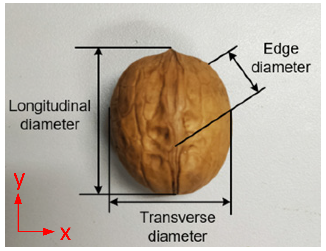
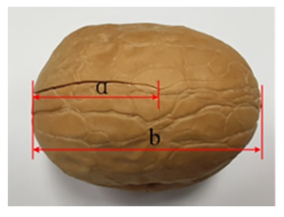
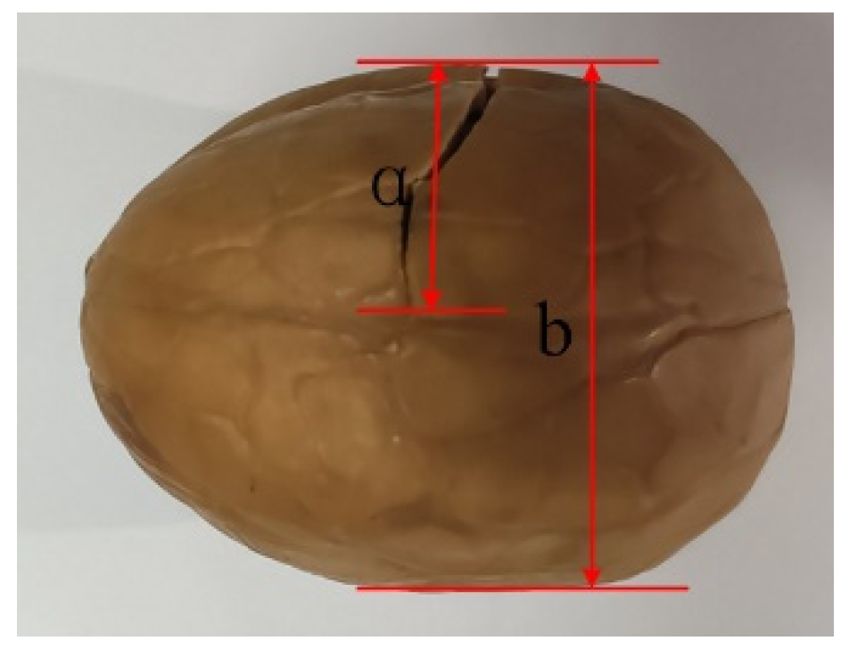
2.2.1. Sphericity Measurement
2.2.2. Sphericity Analysis
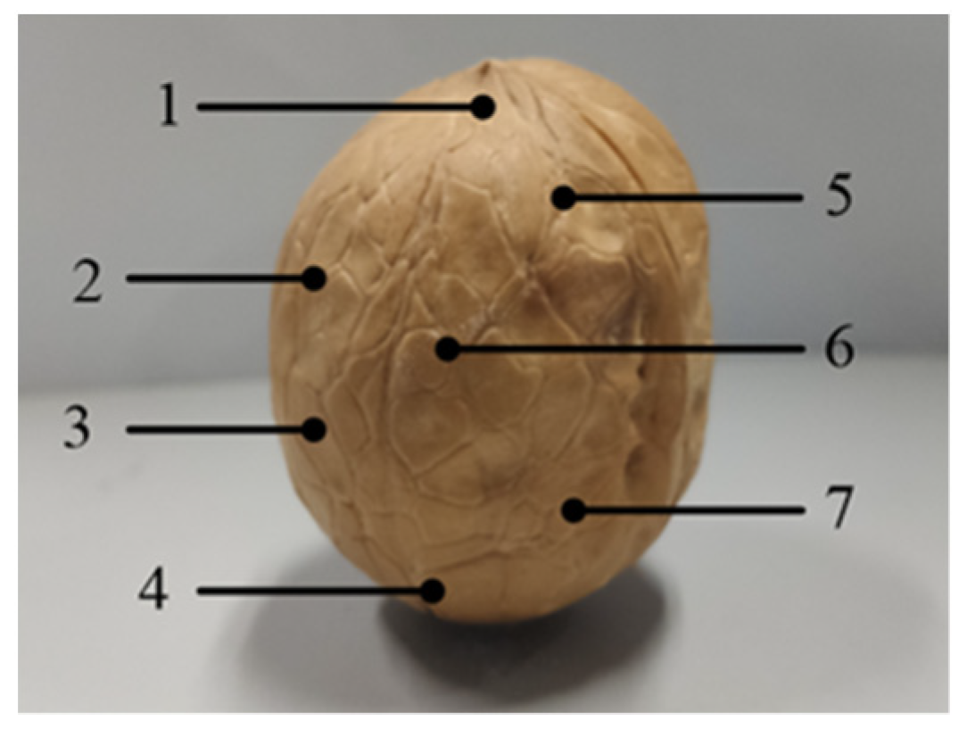
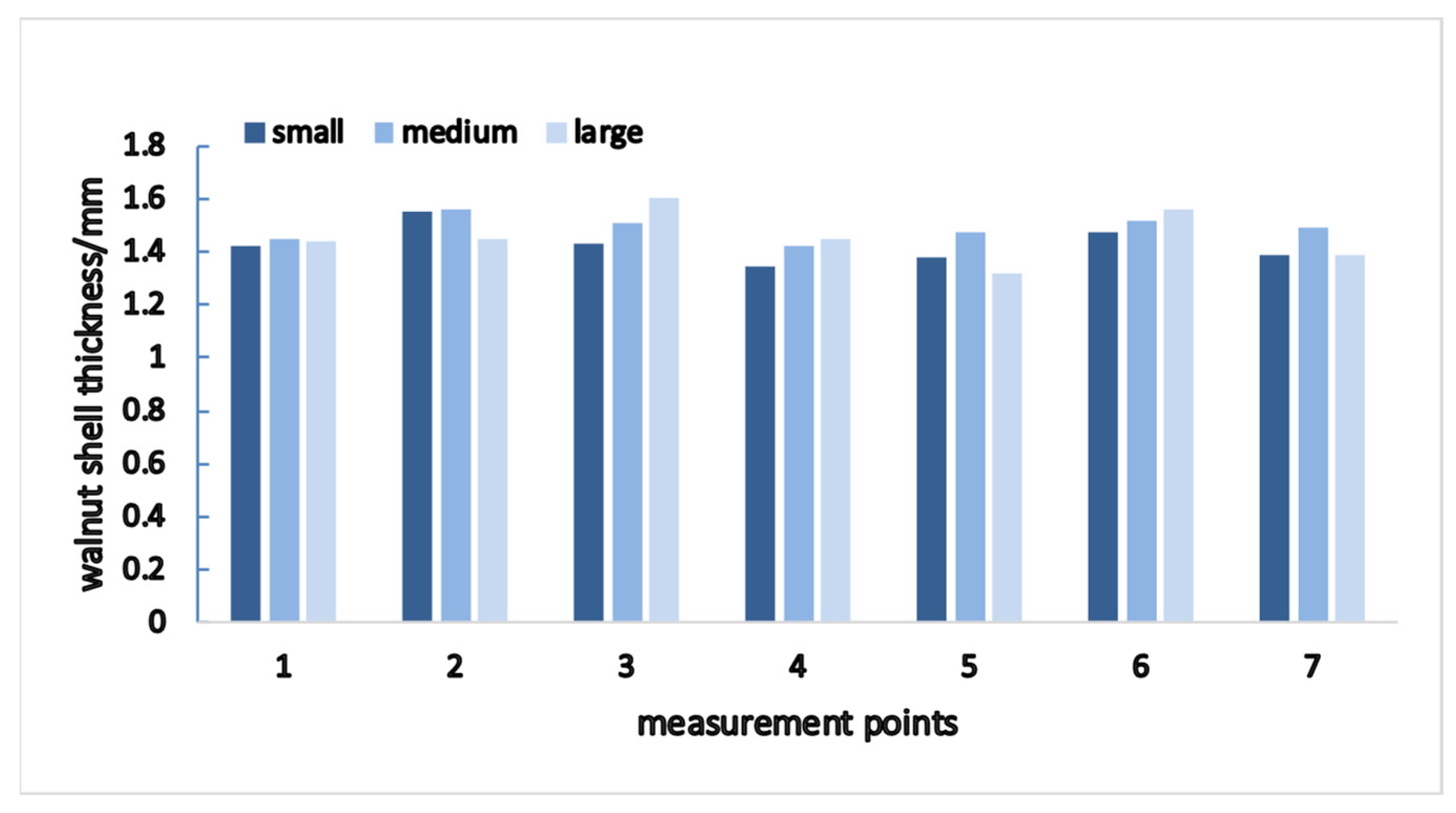
2.2.3. Shell Thickness Measurement
2.2.4. Shell Thickness Analysis
2.3. Fit Verification of Spherical Thin Shell Model
3. Crack Analysis
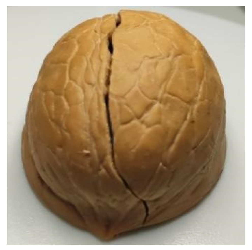
3.1. Crack Type
3.2. Crack Initiation
3.3. Crack Expansion
3.3.1. Longitudinal (Along Grain) Direction
3.3.2. Horizontal (X-Axis) Direction
3.4. Crack Expansion Rate
4. Shell Mechanics Analysis
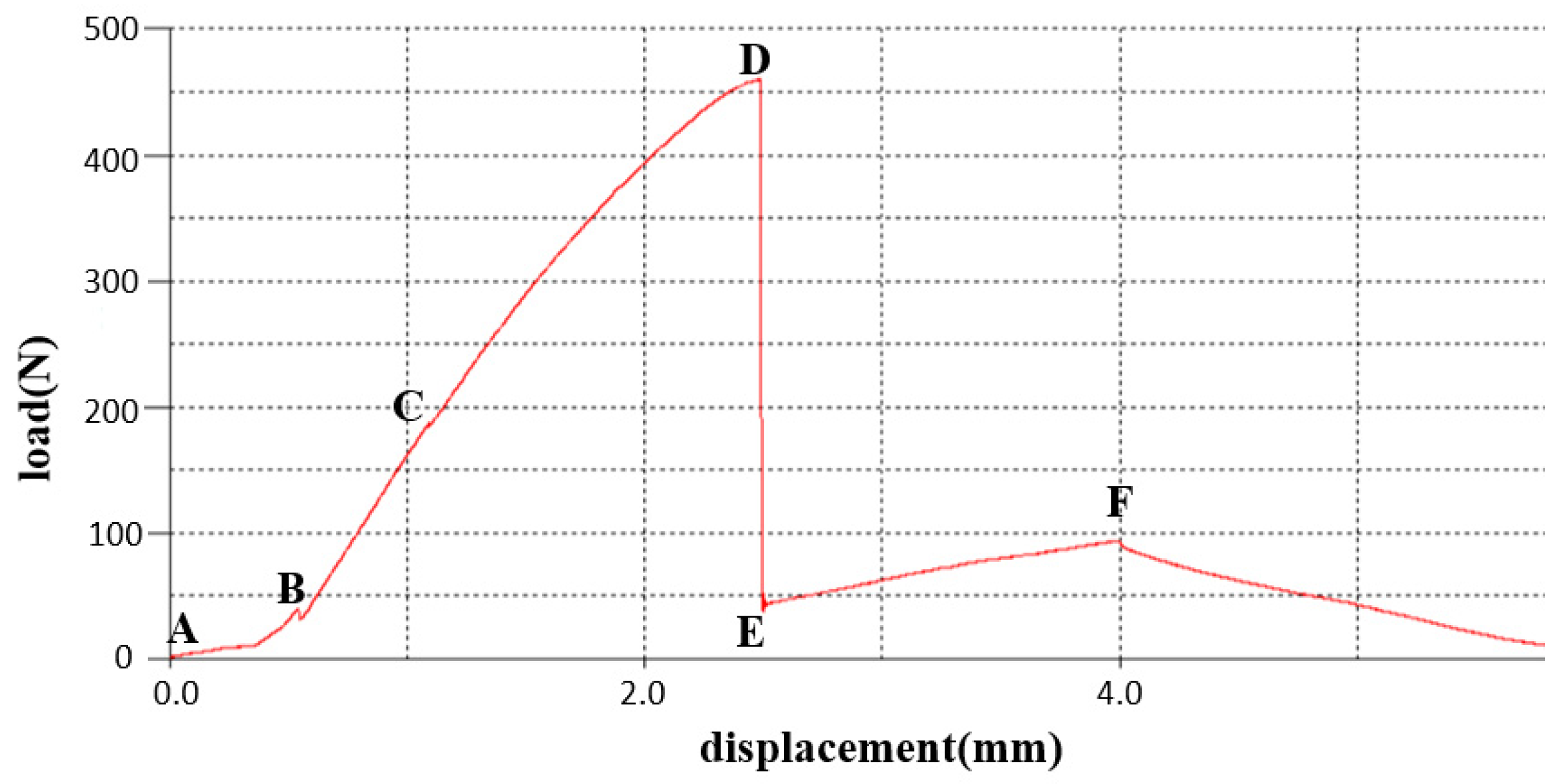
4.1. Shell Deformation Process
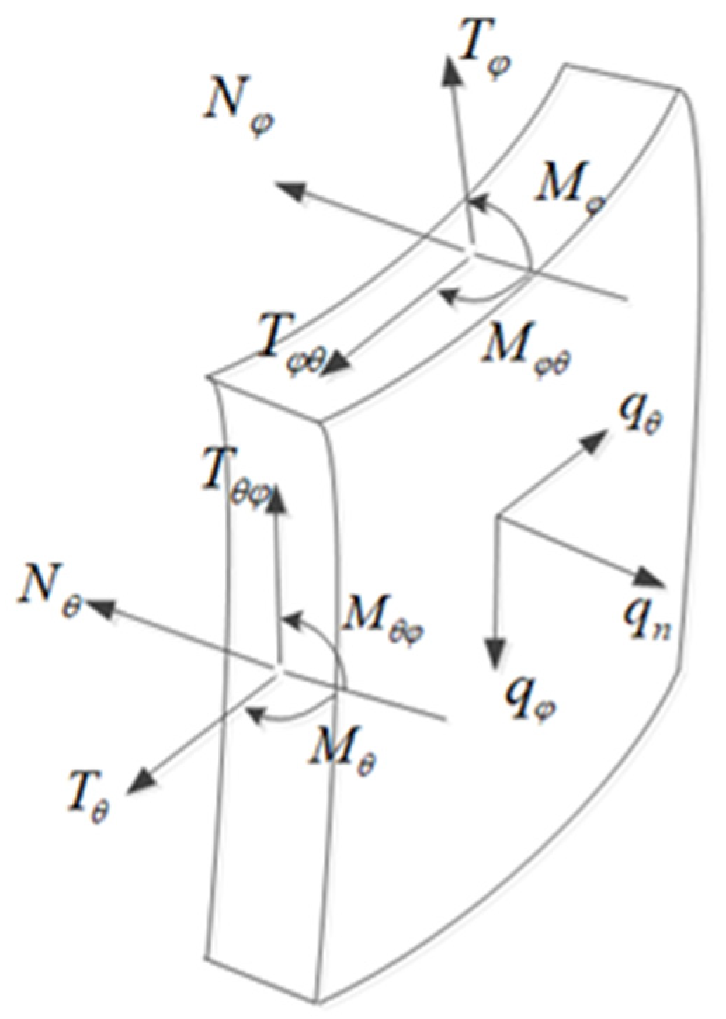
4.2. Internal Force Analysis
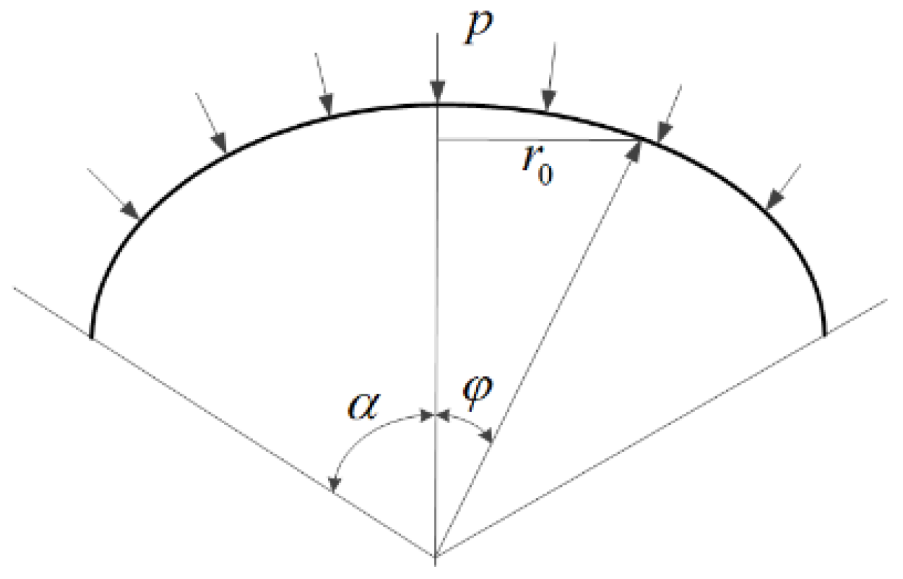
4.2.1. Peripheral Force Region
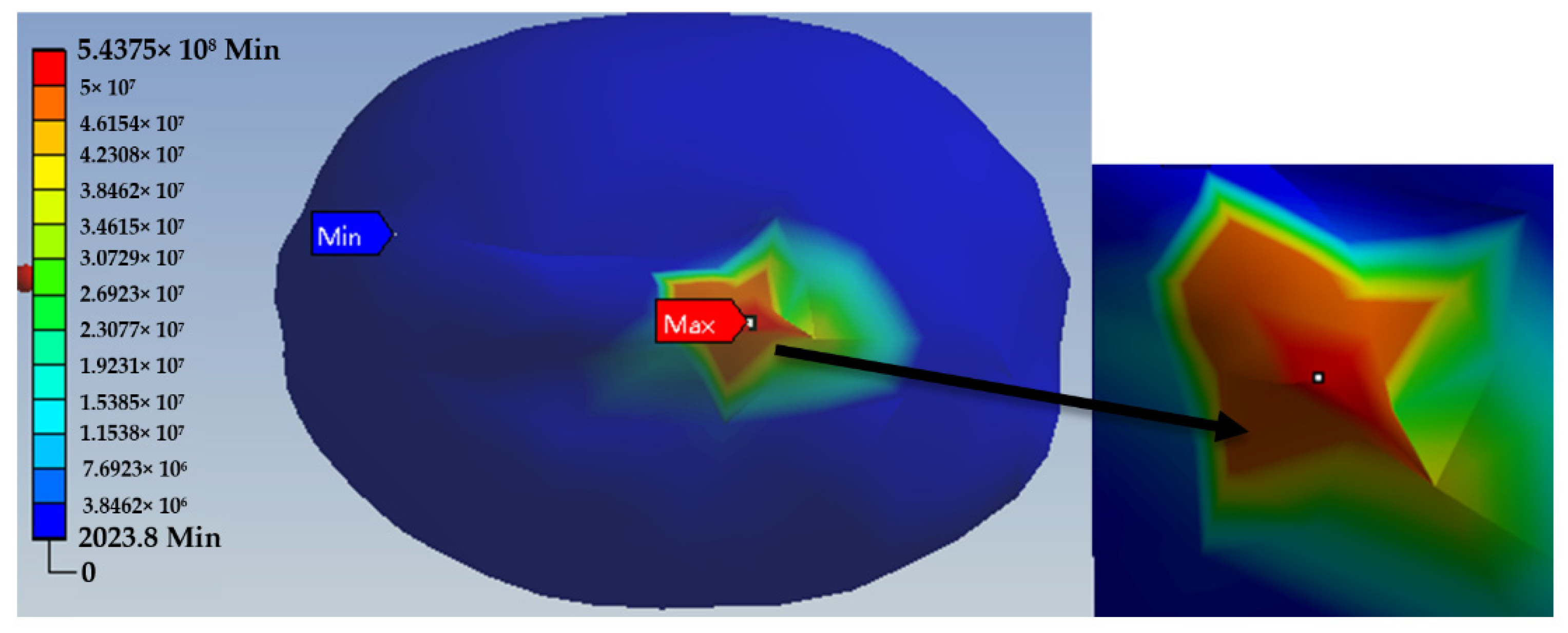
4.2.2. Concentrated Force Action Region
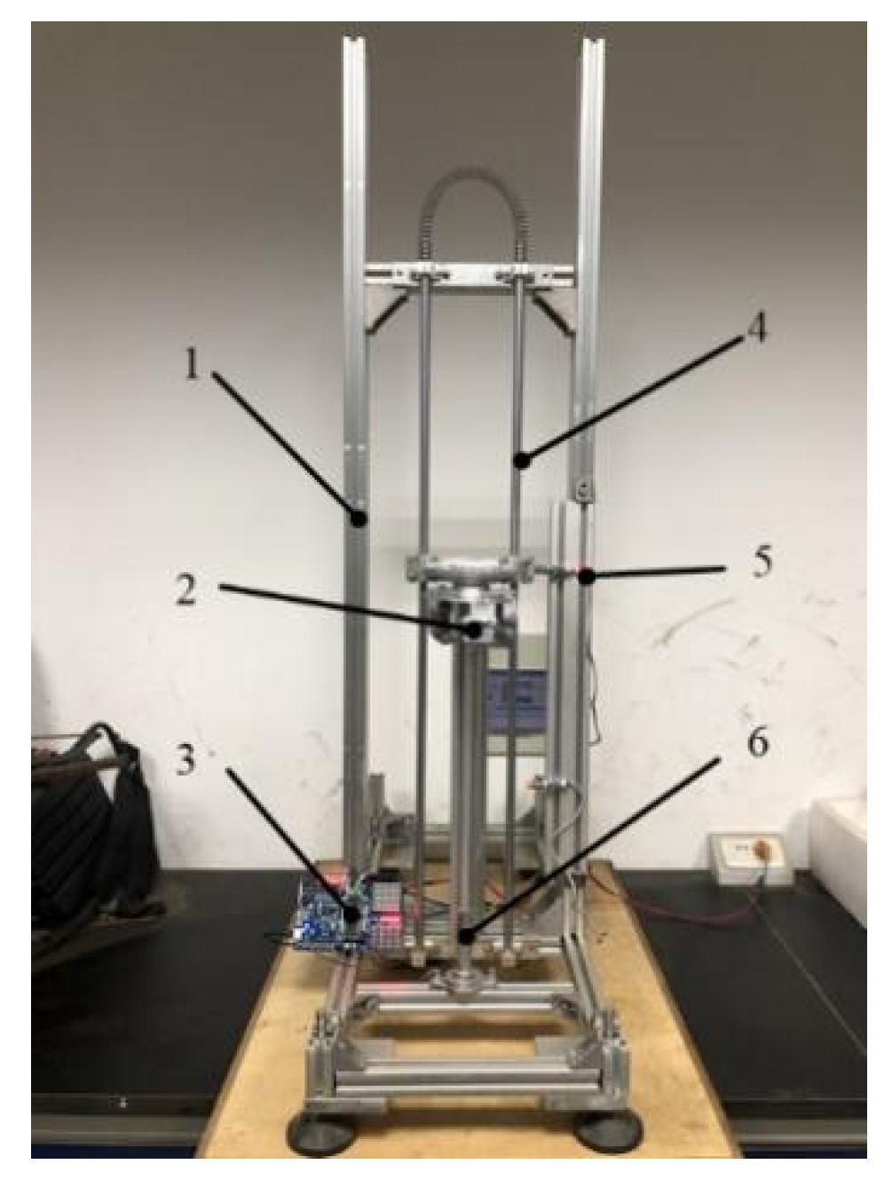
5. Walnut Shell Breaking Experiments under Unidirectional Load
5.1. Test Procedure
5.2. Test Results
6. Discussion and Conclusions
- (1)
- The walnut shell was divided into the concentrated force region and peripheral force region. In the peripheral force domain, the internal forces of the shell surface in all directions were calculated to be equal based on the momentless theory. In the concentrated force region, the finite element analysis method was used to intuitively exhibit the gradient distribution of the internal force on the shell from inside to outside. Based on these results, we suggested that the unidirectional force during shell breaking should be loaded on the middle of the walnut shell surface so as to make the shell surface force load uniform, thus improving the shell breaking effect and efficiency.
- (2)
- Walnut cracks included type Ⅰ and type Ⅱ cracks. According to the maximum stress yield criterion, crack initiation occurred at the position where the load was applied, and the crack expansion direction was determined according to the fracture criterion and the stress intensity factor. Finally, the crack expansion rate could be used to determine the walnut shell breaking position and force loading time so as to obtain the complete kernel and improve the shell-kernel separation rate.
- (3)
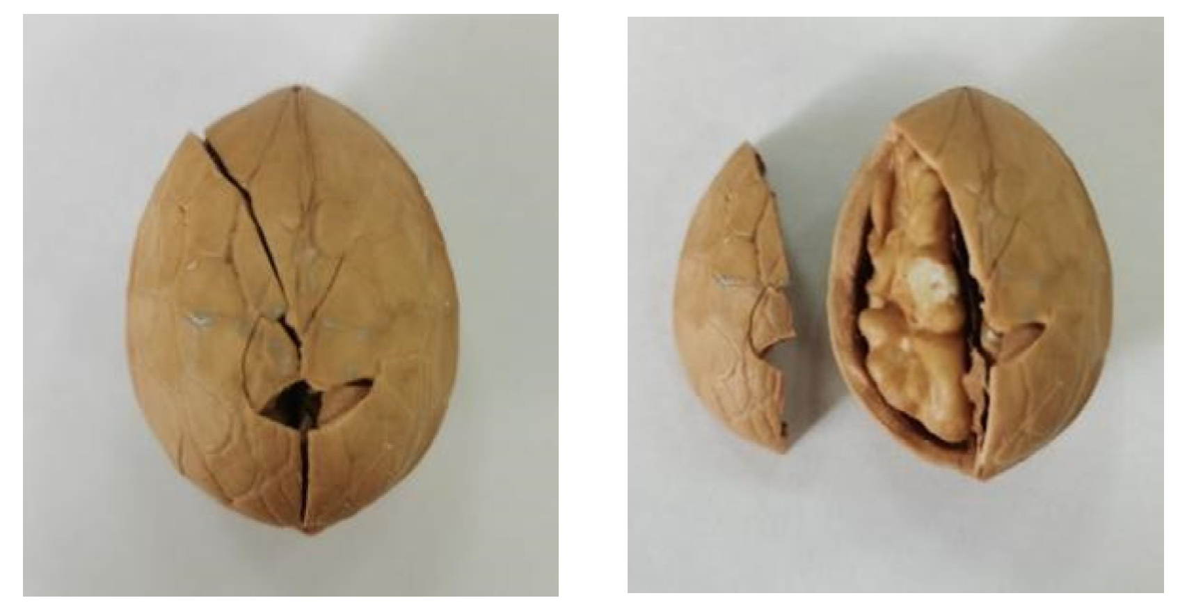
- The actually measured walnut shell breaking force under unidirectional load was in line with the theoretical value, and the observed crack extension direction was consistent with our hypothesis of fracture along the longitudinal texture. These results jointly verified the reliability of the theoretical model proposed in this study. Our results can provide a theoretical basis for the development and structural optimization of shell-breaking machinery.
Author Contributions
Funding
Institutional Review Board Statement
Informed Consent Statement
Data Availability Statement
Conflicts of Interest
References
- Song, Y.; Wang, X.H.; Zhang, R.; Liu, C.H.; Yu, S.Q.; Gao, S.; Zhang, R.L. Comparison of Quality Differences Among Varieties of Walnut from Xinjiang. J. Chin. Cereals Oils Assoc. 2019, 34, 91–97. [Google Scholar]
- Lu, J.; Zhao, A.Q.; Cheng, C. Nutritional composition and physiological activity of walnut and its development and utilization. Food Mach. 2014, 30, 238–242. [Google Scholar]
- Sütyemez, M.; Bükücü, Ş.B.; Özcan, A. ‘Helete Güneşi:’ A New Walnut Cultivar with Late Leafing, Early Harvest Date, and Superior Nut Traits. Agriculture 2021, 11, 991. [Google Scholar] [CrossRef]
- Aleksandra, V.C.; Marie-Christine, R.; Jacqueline, V.; Sara, K.; Arijana, M.; Draženka, K.; Estelle, B. Valorisation of walnut shell and pea pod as novel sources for the production of xylooligosaccharides. Carbohydr. Polym. 2021, 263, 117932. [Google Scholar]
- Liu, M.Z.; Li, C.H.; Cao, C.M. Research progress of key technology and device for size-grading shell-breaking and shell-kernel separation of walnut. Trans. Chin. Soc. Agric. Eng. 2020, 36, 294–310. [Google Scholar]
- Wang, J.; Liu, M.; Wu, H.; Peng, J.; Peng, B.; Yang, Y.; Cao, M.; Wei, H.; Xie, H. Design and Key Parameter Optimization of Conic Roller Shelling Device Based on Walnut Moisture-Regulating Treatments. Agriculture 2022, 12, 561. [Google Scholar] [CrossRef]
- Khir, R.; Pan, Z.; Atungulu, G.G.; Thompson, J.F.; Shao, D. Size and moisture distribution characteristics of walnut and their components. Food Bioprocess Technol 2013, 6, 771–782. [Google Scholar] [CrossRef]
- Froogh, S.; Mohammadali, H.D. Mechanical behavior of walnut under cracking conditions. J. Appl. Sci. 2008, 8, 886–890. [Google Scholar]
- Kocturk, B.O.; Gurhan, R. Determination of mechanical properties of various walnut according to different moisture levels. J. Agric. Sci. 2007, 13, 69–74. [Google Scholar]
- Wu, Z.Y. Mechanical analysis of walnut shelling. J. Nanjing Agric. Univ. 1995, 18, 116–123. [Google Scholar]
- Tu, C.; Yang, W.; Yin, Q.J. Optimization of technical parameters of breaking macadamia nut shell and finite element analysis of compression characteristics. Trans. Chin. Soc. Agric. Eng. 2015, 31, 272–277. [Google Scholar]
- Yan, R.; Gao, J.; Zheng, J.H. Analysis of mechanical properties of walnut shell breaking based on workbench. Agric. Mech. Res. 2014, 36, 38–41. [Google Scholar]
- Ojolo, S.J.; Damisa, O.; Orisaleye, J.I. Design and development of cashew nut shelling machine. J. Engineering. Des. Technol. 2010, 8, 146–157. [Google Scholar] [CrossRef]
- Li, Z.X.; Liu, K.; Yang, L.L. Design and experiment of cone basket walnut shell breaking device. J. Agric. Mach. 2012, 43, 146–152. [Google Scholar]
- Liu, M.Z.; Li, C.H.; Zhang, Y.B. Shell Crushing Mechanism Analysis and Performance Test of Flexible-belt Shearing Extrusion for Walnut. Trans. Chin. Soc. Agric. Mach. 2016, 47, 266–273. [Google Scholar]
- Ding, R.; Cao, C.M.; Zhan, C. Design and experiment of bionic-impact type pecan shell breaker. Trans. Chin. Soc. Agric. Eng. 2017, 33, 257–264. [Google Scholar]
- Xu, B.H.; Wang, Y.X.; Zhao, Y.H. Advances in the study of the toughness of wood-striped fractures. Mech. Pract. 2016, 38, 493–500. [Google Scholar]
- Norman, E.D.; Jiang, S.Y.; Zhang, Y.Q. Mechanical Behavior of Engineering Materials; China Machine Press: Beijing, China, 2015. [Google Scholar]
- Law, B.; Gong, J.H. Fracture Mechanics of Brittle Solids; Higher Education Press: Beijing, China, 2010. [Google Scholar]


| Factors | Sum of Squares | Degree of Freedom | Mean Square | F | p |
|---|---|---|---|---|---|
| Factor A | 0.01384 | 2 | 0.00692 | 3.89 | 0.15 |
| Factor B | 0.05885 | 6 | 0.00981 | 2.99 | 0.04 |
| Error | 0.03710 | 12 | 0.00309 | ||
| Sum | 0.10978 | 20 |
| Sizes | Small (27 ± 2 mm) | Medium (33 ± 2 mm) | Large (35 ± 2 mm) | |
|---|---|---|---|---|
| Shell-Breaking Force | ||||
| Calculated Value/N | 317.3 | 303.7 | 312.7 | |
| Observed Value/N | 329.6 | 316.1 | 329.2 | |
| Deviation/% | 3.7 | 3.9 | 5.0 | |
| Initial Conditions | Elastic Modulus E | Density ρ | Initial Crack Length c0 | Average Length of Cracks a |
|---|---|---|---|---|
| Initial Value | 0.18 GPa | 0.5 kg/m3 | 0 | 34.3 mm |
| Type | The Longitudinal Sound Rate v1 | The Limit Speed vT | f | The Crack Expansion Rate v(c) |
|---|---|---|---|---|
| Results | 19 km/s | 7.22 km/s | 1 | 34.3 mm |
Publisher’s Note: MDPI stays neutral with regard to jurisdictional claims in published maps and institutional affiliations. |
© 2022 by the authors. Licensee MDPI, Basel, Switzerland. This article is an open access article distributed under the terms and conditions of the Creative Commons Attribution (CC BY) license (https://creativecommons.org/licenses/by/4.0/).
Share and Cite
Bao, X.; Chen, B.; Dai, P.; Li, Y.; Mao, J. Construction and Verification of Spherical Thin Shell Model for Revealing Walnut Shell Crack Initiation and Expansion Mechanism. Agriculture 2022, 12, 1446. https://doi.org/10.3390/agriculture12091446
Bao X, Chen B, Dai P, Li Y, Mao J. Construction and Verification of Spherical Thin Shell Model for Revealing Walnut Shell Crack Initiation and Expansion Mechanism. Agriculture. 2022; 12(9):1446. https://doi.org/10.3390/agriculture12091446
Chicago/Turabian StyleBao, Xiulan, Biyu Chen, Peng Dai, Yishu Li, and Jincheng Mao. 2022. "Construction and Verification of Spherical Thin Shell Model for Revealing Walnut Shell Crack Initiation and Expansion Mechanism" Agriculture 12, no. 9: 1446. https://doi.org/10.3390/agriculture12091446