Article

Research on Integrated Navigation System of Agricultural Machinery Based on RTK-BDS/INS

1
School of Electrical & Information Engineering, Anhui University of Science and Technology, Huainan 232001, China
2
Institute of Environment-Friendly Materials and Occupational Health, Anhui University of Science and Technology, Wuhu 241003, China
*
Author to whom correspondence should be addressed.
Agriculture 2022, 12(8), 1169; https://doi.org/10.3390/agriculture12081169
Submission received: 4 July 2022 / Revised: 2 August 2022 / Accepted: 3 August 2022 / Published: 5 August 2022

Abstract

:
To improve the positioning accuracy and reliability of autonomous navigation agricultural machinery and reduce the cost of high-precision positioning, an integrated navigation system based on Real-Time Dynamic Kinematic BeiDou Navigation Satellite System (RTK-BDS) and Inertial Navigation System (INS) is designed in this study. On the one hand, an autonomous navigation control board is designed and made in the system, which integrates BDS high-precision analysis module, Inertial Measurement Unit (IMU) module, and radio module, and realizes the integrated navigation algorithm on the control board. On the other hand, low-cost RTK technology is realized by building differential reference stations and vehicle-mounted mobile stations. Experiments are carried out on actual farm machinery under different road conditions including open road, signal-shielded road, and urban congested road. According to the angular velocity and acceleration information from INS and the position and velocity information from the BDS high-precision analysis module, the system uses Kalman filter algorithm for data fusion to calculate the precise position, velocity, and attitude information of agricultural machinery in real time. The experimental results show that the position error of the integrated navigation system on the open road is within 3 cm, the azimuth error is within 0.6°, and the inclination error is within 1°, all of which converge rapidly when encountering bad road conditions. It can be known from the experimental results that the RTK-BDS/INS integrated navigation system has high positioning accuracy, strong adaptive anti-interference ability, and low implementation cost of RTK technology, which provides a reliable way for automatic navigation control of agricultural machinery.

1. Introduction

China is a large agricultural country where agricultural production guarantees national development and people’s well-being. With the rapid development of modernization, agricultural labor force has changed from manpower to mechanization, and the automation of agricultural machinery has become the development goal of the new era. The application of automatic driving in agriculture is one of the key technologies for agricultural machinery intelligentization [1], which can effectively solve the problem of insufficient agricultural manpower, and is of great significance for improving operational efficiency and reducing production costs [2].
There are often high requirements for positioning accuracy when driving autonomous navigation agricultural machinery. Thus, the concept of precision agriculture [3] is proposed, which requires for centimeter-level positioning accuracy. To meet the demands for positioning accuracy of agricultural machinery, many scholars have conducted different research and designs on the positioning and navigation system of agricultural machinery. Anon et al. [4] designed an electro-hydraulic circuit and installed it in the traditional hydraulic steering circuit of a small agricultural tractor, which was connected with the microcontroller and GPS navigation module to achieve steering speed and position control. Chin Tan et al. carried out experiments on wheeled mobile robot and optimized the design of PID controller parameters in the path tracking task, which effectively reduced the process of manual parameter adjustment and could better drive the DC motor of the controller [5]. Gao et al. [6] independently developed a mechanical angle sensor to detect crop rows and return the detected value as the deviation to the guidance controller. Their experimental results at three different speeds showed that the average error was less than 0.1 m, which met the navigation requirements of corn combine harvesters. Nam et al. [7] designed a PI tracking controller to directly control the steering wheel through the motor and provide feedback compensation. The control system had good stability and robustness. Takai et al. [8] designed a crawler tractor that was capable of autonomous navigation and adopted hydrostatic system for steering and gear shifting, of which the horizontal mean square error of linear navigation test was less than 0.05 m. Backman et al. [9] realized the accurate tracking of straight path of tractors with a lateral deviation less than 0.1 at the speed of 3.33 m/s by using the nonlinear model predictive control method to control the steering of tractors through the hydraulic system. However, those navigation systems designed from the hydraulic transmission, PID control and other aspects were complex to be transformed and of poor portability.
In this case, the Global Navigation Satellite System (GNSS) [10,11], Inertial Navigation System (INS) [12,13,14,15,16,17], laser radar [18], and visual navigation system [19] have been widely used in the positioning and navigation of agricultural machinery. Among them, GNSS is often used in combination with real-time kinematic (RTK) technology [20], and other navigation systems [21,22]. Bakker et al. developed an autonomous field navigation system based on RTK-DGPS (Real-time kinematic Differential Global Positioning System) and tested it on a weeding robot. When driving the robot along a straight path at the speed of 0.3 m/s in the field, its standard deviation, mean value, and minimum and maximum lateral errors were 1.6 cm, 0.1 cm, −4.5 cm, and 3.4 cm, respectively; and the standard deviation, mean value, and minimum and maximum of the heading error were 0.008 rad, 0.000 rad, −0.022 rad, and 0.023 rad, respectively. This indicated that the autonomous navigation of the robot was realized [23]. Masella et al. introduced an RTK-GPS developed by Marconi Company of Canada, which proved through many tests that it could obtain an accuracy of about 20 cm in real time [24]. GNSS is easy to lose signals due to environmental interference while INS is hard to be affected, but the system error of INS accumulates over time. Therefore, the two systems were combined by scholars for research. Kise et al. designed an integrated tractor navigation system with fiber optic gyroscope and RTK-GPS, and the test showed that the error was within 6 cm when driving at the speed of 1.5 m/s [25]. Zhang Meina et al. fused RTK-DGPS and inertial sensor to calculate vehicle heading deviation, and the results showed that the average error of heading deviation was 0.936°, 3.6418°, and 2.7562°, respectively, under three driving conditions: straight line, circular, and arbitrary curves [26]. With the completion and opening of the BeiDou-3 global navigation satellite system [27,28], the performance of the BDS has been further improved. Zhang Yize et al. comprehensively evaluated the system status and global positioning performance of the BDS in terms of single point positioning (SPP) and real-time kinematic (RTK) performance, and the results showed that its positioning accuracy was at the same level as GPS [29]. Pan Lin et al. tested the real-time precision single point positioning performance of BDS, and the results showed that, in static mode, the accuracy of BDS-3/BDS-2 in the east, north, and upward positions were, respectively, 1.8 dm, 1.2 cm, and 2.5 cm, while in motion mode, the corresponding statistics in the three directions were 6.7 cm, 5.1 cm, and 10.4 cm, respectively [30]. Xiong Bin et al. applied BDS to the orchard pesticide applicator and designed an automatic navigation control system of the applicator based on the BeiDou Navigation Satellite System (BDS). The results showed that it could meet the requirements of orchard pesticide application [31]. Wang Jizhong et al. designed a navigation control system of Real Time Kinematic BeiDou Navigation Satellite System (RTK-BDS) based on carrier phase differential technology. The test results showed that the navigation control lateral overshoot was 4.58 cm, the maximum lateral error was within the range of ±4 cm, and the average lateral error was within the range of ±1.5 cm [32]. However, at present, there are few studies on applying the RTK technology to the BeiDou navigation system and integrating it with inertial navigation system to form an integrated navigation system. Moreover, the use of RTK technology often obtains relevant high-precision positioning service by accessing network cors accounts through NTRIP [33,34,35], which generates high costs.
This paper aims to improve the positioning accuracy and reliability of autonomous navigation agricultural machinery, and in the meantime reduce the costs needed for high-precision positioning. An integrated navigation system based on RTK-BDS/INS is designed, and a highly integrated control board for autonomous navigation agricultural machinery is also designed and manufactured to solve the problems such as BDS navigation signals are easy to be interfered with and INS navigation errors accumulate. Moreover, RTK-BDS is realized with radio transmission through establishment of simple base stations and mobile stations, which reduces the system cost, improves the accuracy and reliability of system operation, and realizes the accurate centimeter-level positioning.

2. RTK-BDS/INS Integrated Navigation System
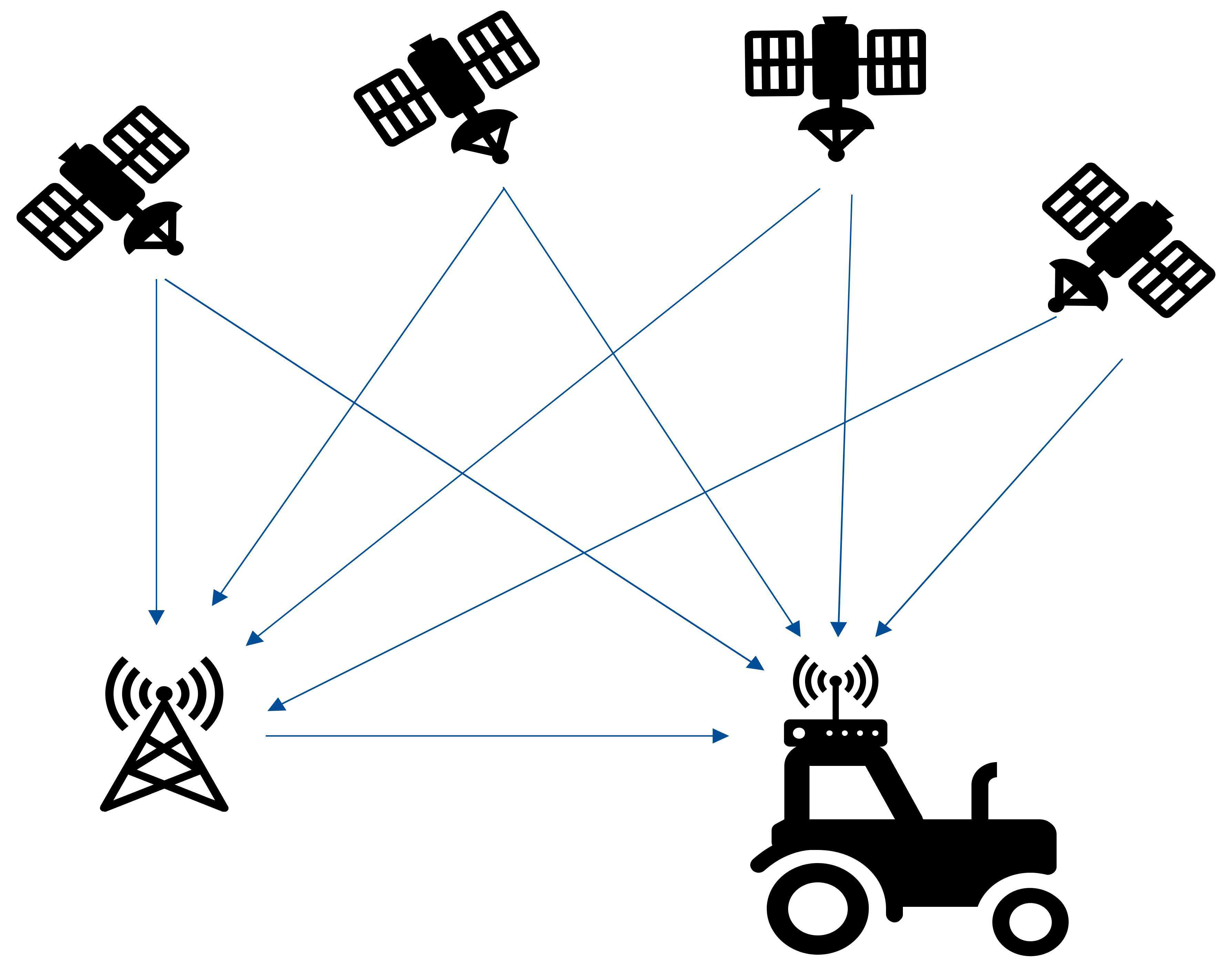
2.1. RTK-BDS

BeiDou Navigation Satellite System (BDS) is a global navigation satellite system independently built and operated by China. It can provide all-weather, all-day, and high-precision positioning, navigation, and timing service to global users, which is an important national space-time infrastructure.
BDS belongs to one of GNSS, so the essence of BDS positioning is the resection of spatial distance. At least four satellites are needed to determine the position coordinates of the points to be measured [36]. However, BDS positioning alone cannot meet the position accuracy of agricultural machinery operations. Thus, RTK technology and BDS are combined in this paper.
RTK is, in essence, a difference method, in which the objects of difference are the observed carrier phase values of two stations. Its working principle is as follows: first, establish a fixed base station; next, place a receiver on it to receive BDS signals and another receiver as a user using the receiver, which can also receive BDS signals; the base station collects observed carrier phase values in real time and transmits them to the user receiver by radio; then, the user receiver collects both BDS observed carrier phase values and the observed carrier phase values from the base station for difference calculation so as to obtain the positioning data. RTK positioning is shown in Figure 1.

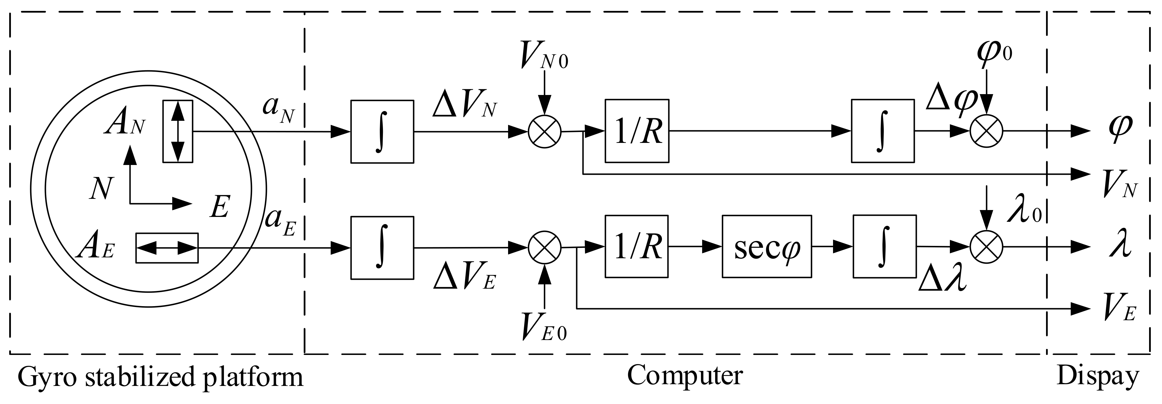
2.2. Inertial Navigation System

The reference theory of INS (inertial navigation system) is Newton’s Second Law, which uses inertial measure units (IMUs) for measurement. Accelerometers and gyroscopes are used to measure the acceleration and angular velocity of carriers. To obtain the navigation information of carriers such as attitude, position, and speed, we adopt the integral calculation method. Figure 2 is a simplified schematic diagram of inertial navigation.
As shown in Figure 2, two accelerometers, AN and AE, are placed on the gyro stabilized platform. The AN sensitive axis is kept to the north to measure the north–south acceleration, while the AE sensitive axis is kept to the east to measure the east–west acceleration. AN acquires the signal aN and AE acquires aE. The velocity component of the carrier is:
V N = 0 t a N d t + V N 0 V E = 0 t a E d t + V E 0
where VN0 and VE0 are the initial northbound velocity and eastbound velocity of the carrier respectively.
By integrating Equation (1) again, the longitude and latitude variations Δλ and Δφ can be obtained. If the initial values of longitude and latitude are known, the instantaneous longitude λ and latitude φ of the carrier can be obtained:
φ = 1 R 0 t V N d t + φ 0 λ = 1 R 0 t V E sec φ d t + λ 0
where λ0 and φ0 are the initial values of longitude and latitude of the carrier, respectively; R is the simplified approximate mean radius of the Earth.
It can be seen from the above inertial navigation principle that the gyro stabilized platform provides coordinate data for the accelerometer to measure the acceleration, and can pick up the carrier attitude angle signal from the corresponding stable axis.
Therefore, even if BeiDou satellite signals are interfered and large errors occur, they can be corrected through the data of the inertial navigation system to ensure the accuracy of positioning.

2.3. Design of the Integrated Navigation System

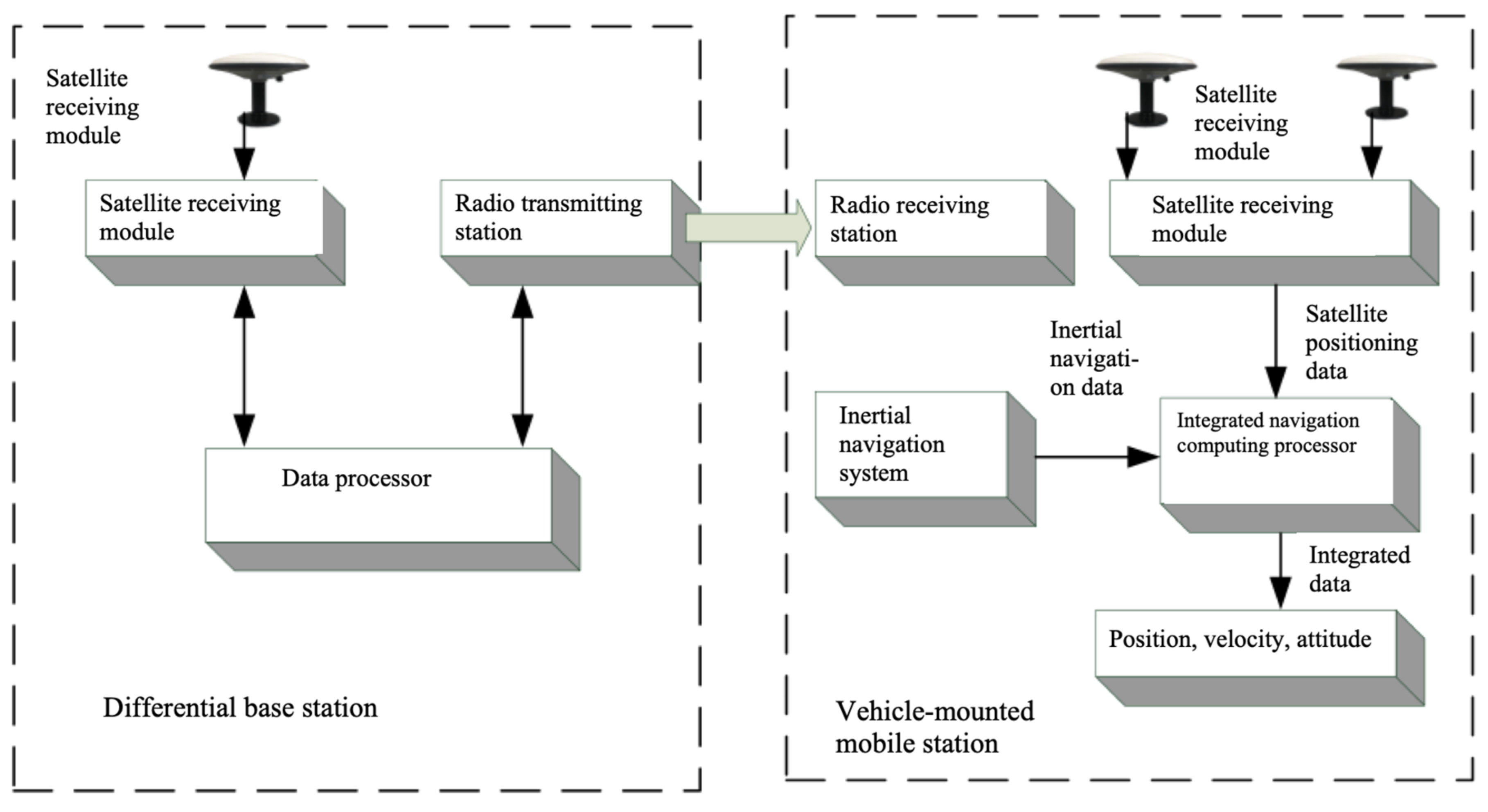
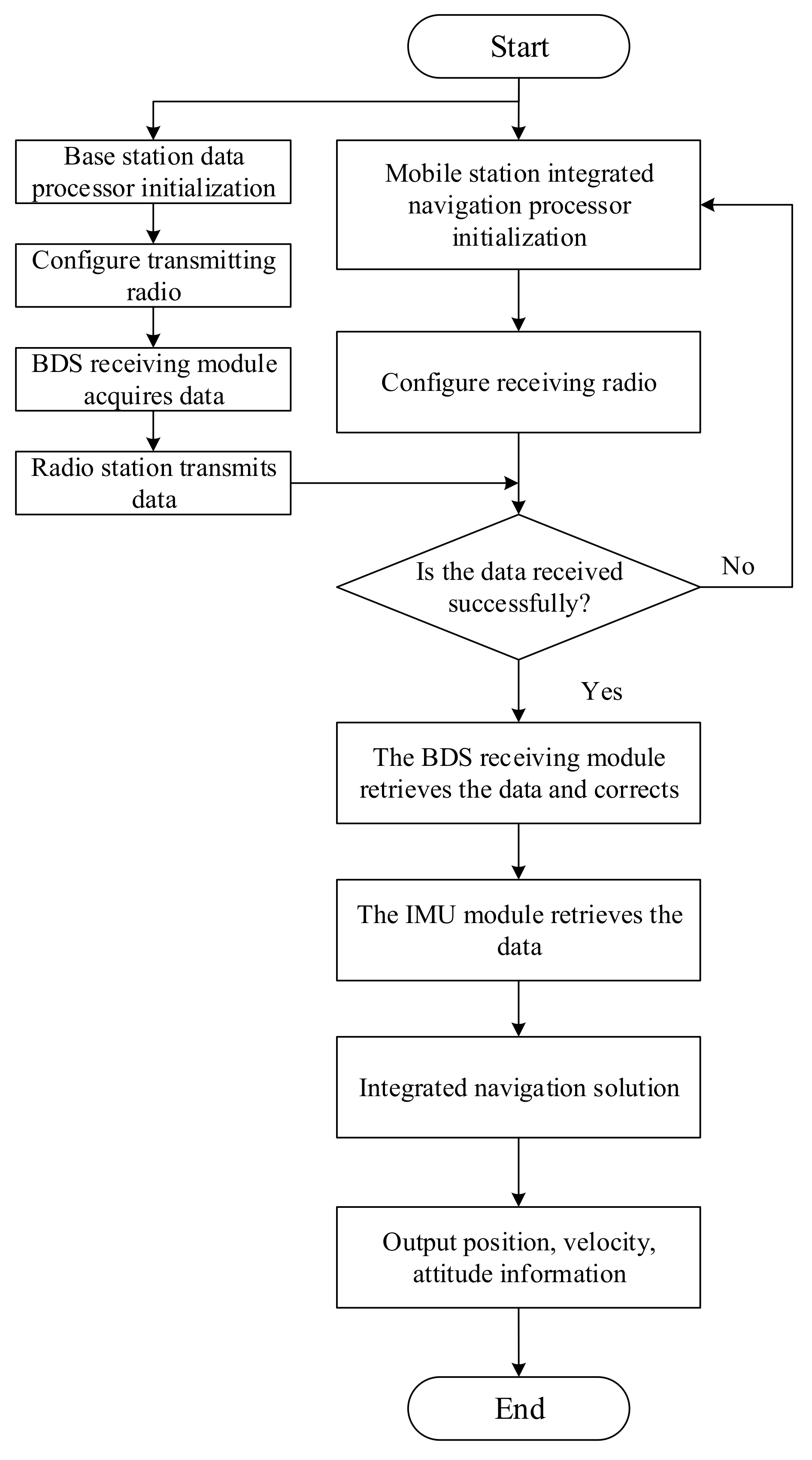
2.3.1. Integrated Navigation System Architecture

The RTK-BDS/INS integrated navigation system is mainly composed of differential reference station and vehicle-mounted mobile station. The former consists of satellite receiving antenna, BDS signal receiving module, data processor, radio station, and radio transmission antenna, and the latter consists of two satellite receiving antennas, BDS signal receiving module, inertial navigation system, integrated navigation data processor, radio station, and radio transmission antenna. The differential reference station transmits the differential data to the vehicle-mounted mobile station through the radio, and calculates the accurate carrier position information. The system structure is shown in Figure 3.
When the integrated navigation system is working, the differential reference station needs to initialize the data processor, BDS signal receiving module, and radio station, and configures the radio station as the transmitter; the vehicle-mounted mobile station needs to initialize the integrated navigation computing processor, BDS signal receiving module, IMU module, and radio station, and configures the radio station as the receiving end that receives the data from the transmitting end. The satellite data from RTK-BDS and the INS data are integrated for navigation solution, so as to obtain the real-time position, velocity, and angle information of the carrier. The workflow of the integrated navigation system is shown in Figure 4.

2.3.2. Data Fusion Algorithm

The data fusion algorithm of RTK-BDS/INS integrated navigation system selects Kalman filter to carry out the optimal combination of RTK-BDS and INS.
Set the general model of integrated navigation system as follows:
x k = Φ k , k 1 + Γ k , k 1 w k 1
z k = H k x k + v k
where x k is the state vector of the system, z k is the measurement vector of the system, w k is the system process noise, v k is the measurement noise, Φ k , k 1 is the system state transition matrix, Γ k , k 1 is the noise input matrix, H k is the measurement matrix, and the subscript k is the time k.
If the estimated state x k and the measured value z k meet the constraints of formulae (3) and (4), w k and v k satisfy the statistical properties of (4), then the state estimate x ^ k of x k can be solved by the following formula.
Further estimation of state:
x ^ k k 1 = Φ k , k 1 x ^ k 1
State estimation:
x ^ k = x ^ k k 1 + K k ( z k H k x ^ k k 1 )
Filter gain matrix:
K k = P k , k 1 H k T ( H k P k , k 1 H k T + R k ) 1
One step prediction error variance matrix:
P k k 1 = Φ k , k 1 P k 1 Φ k k 1 T + Γ k , k 1 Q k 1 Γ k , k 1 T
where Q k is the non-negative definite variance matrix of the system noise w k .
Estimation error variance matrix:
P k = ( I K k H k ) P k k 1 ( I K k H k ) T + K k R k K k T
where R k is the positive definite variance matrix of measured system noise v k .
Formula (7) can be further transformed to:
K k = P k H k T R k 1
Formula (9) is equivalent to:
P k = ( I K k H k ) P k k 1
Formulae (5) to (11) are the basic Kalman filter equations of the system.

3. Experimental Verification

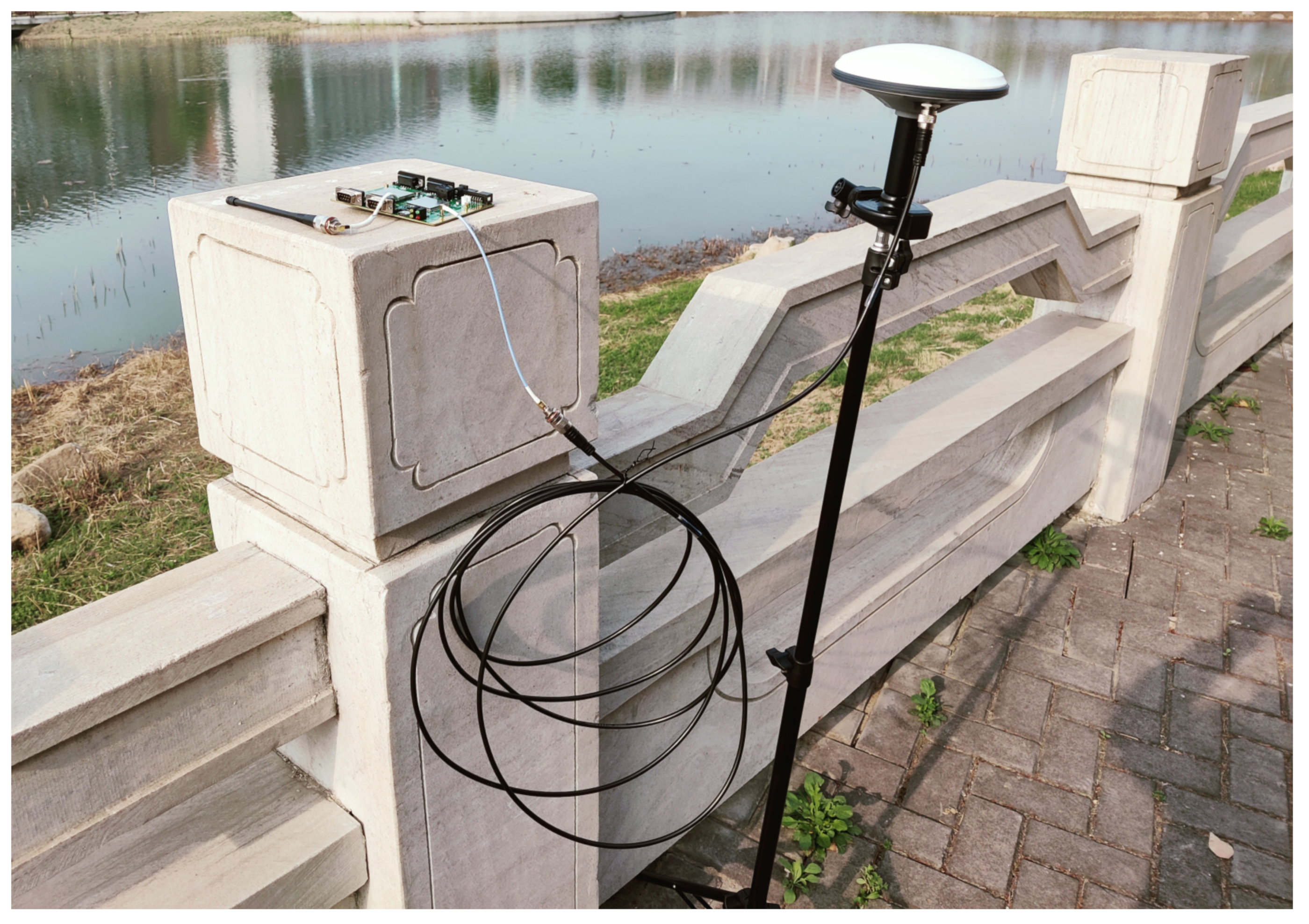
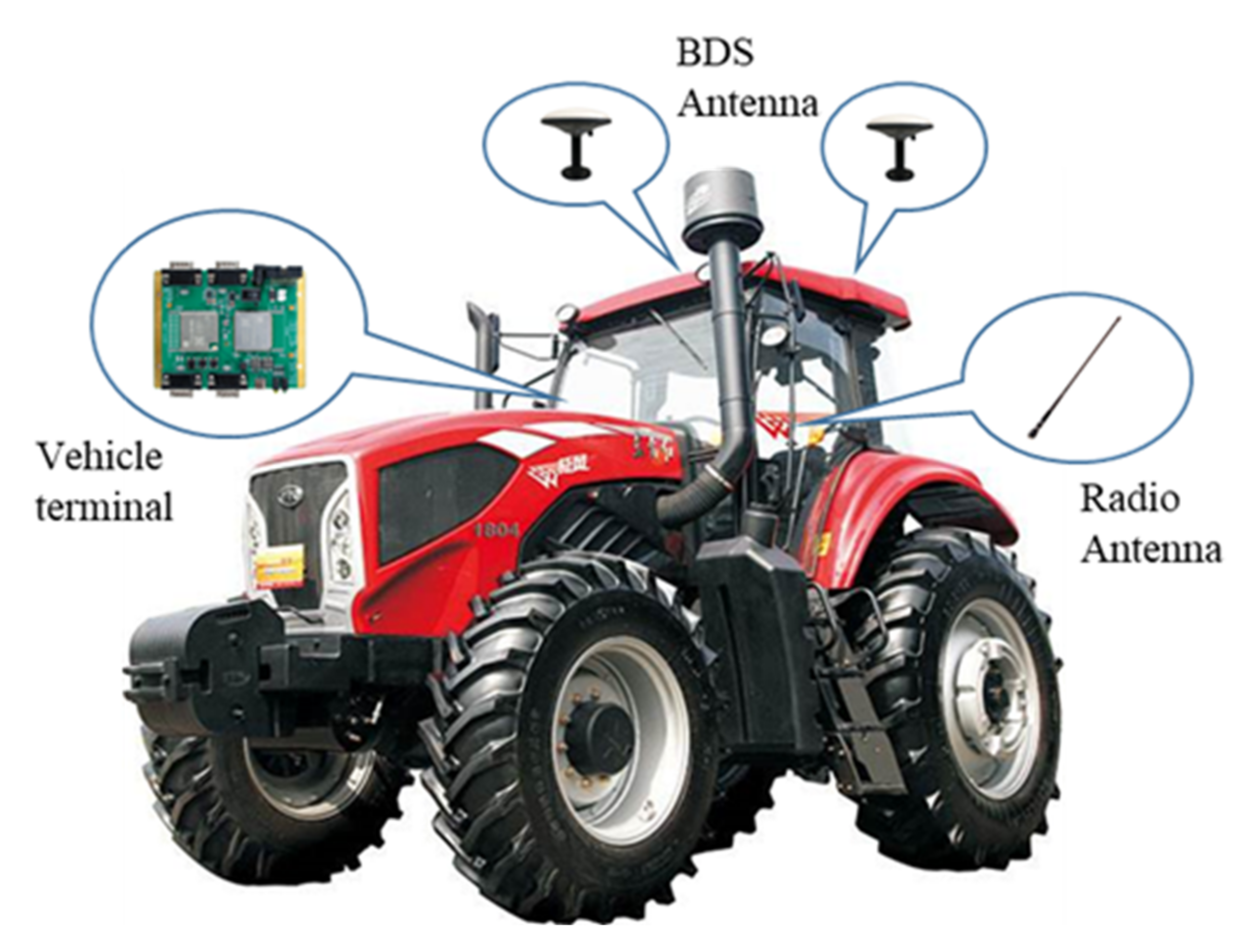
3.1. Experiment Platform
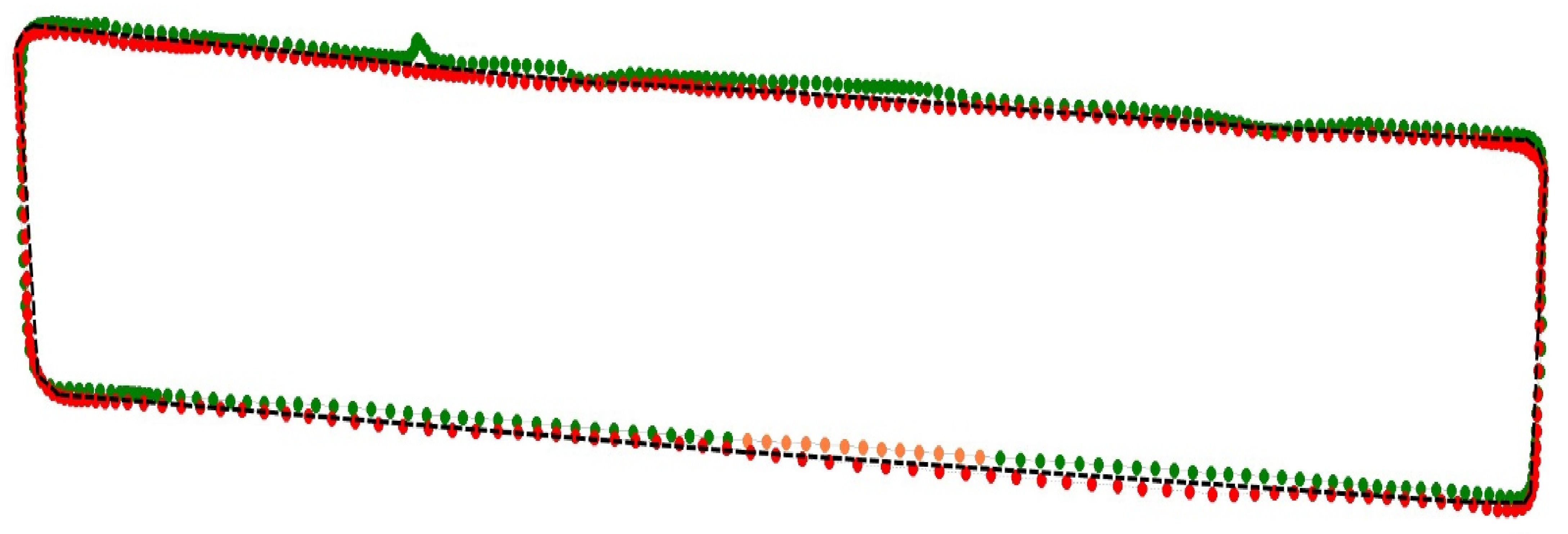
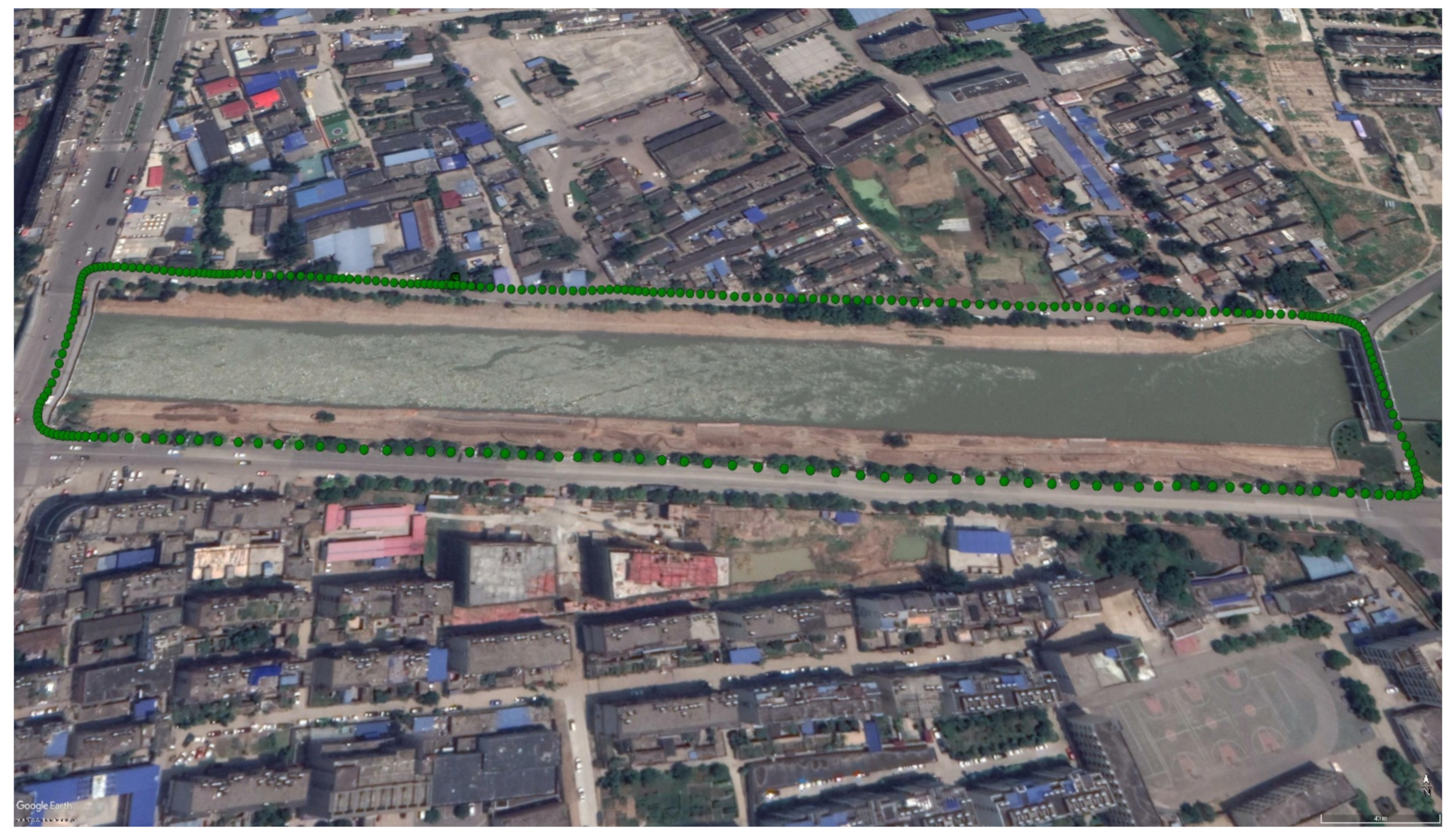
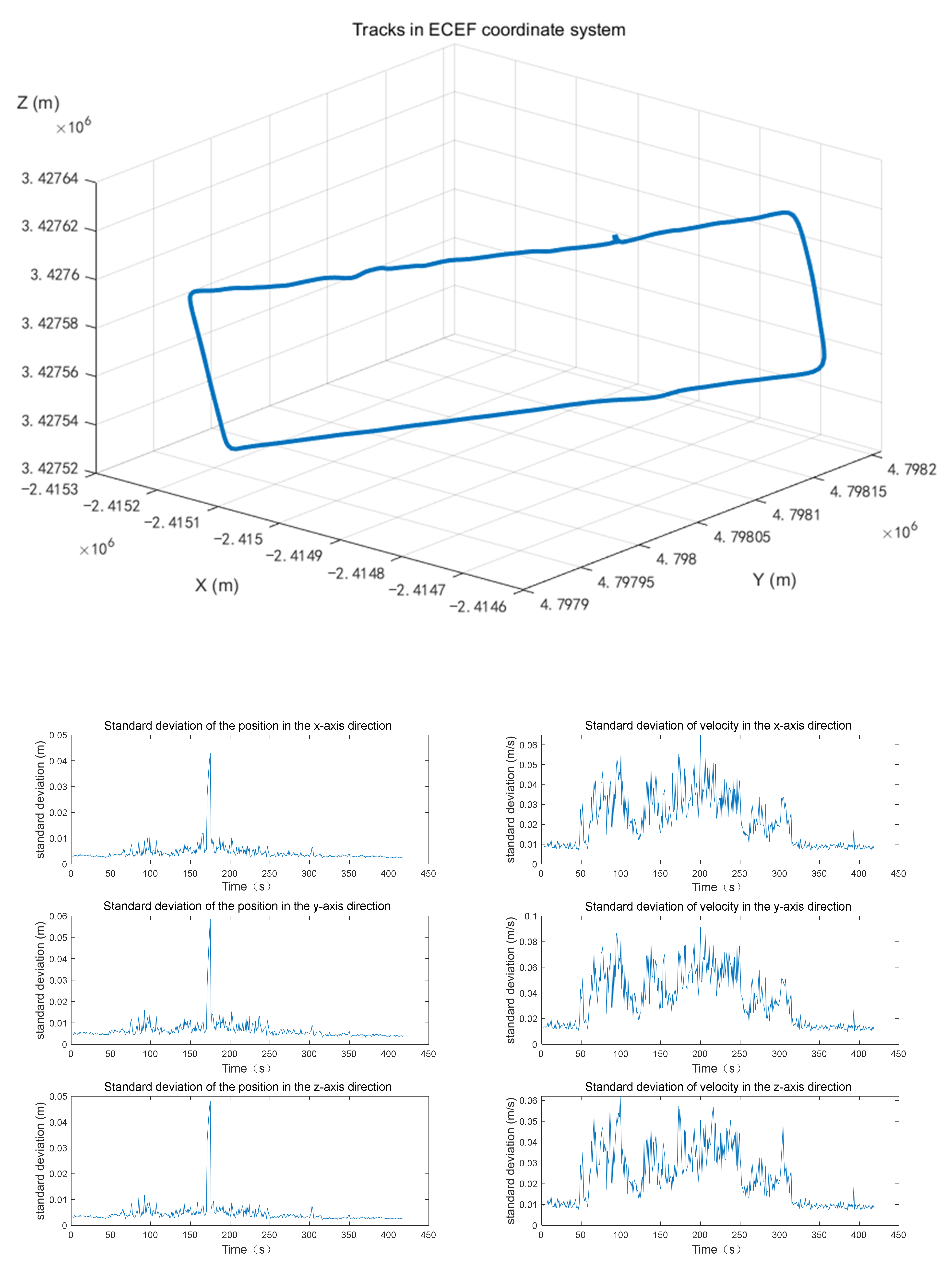
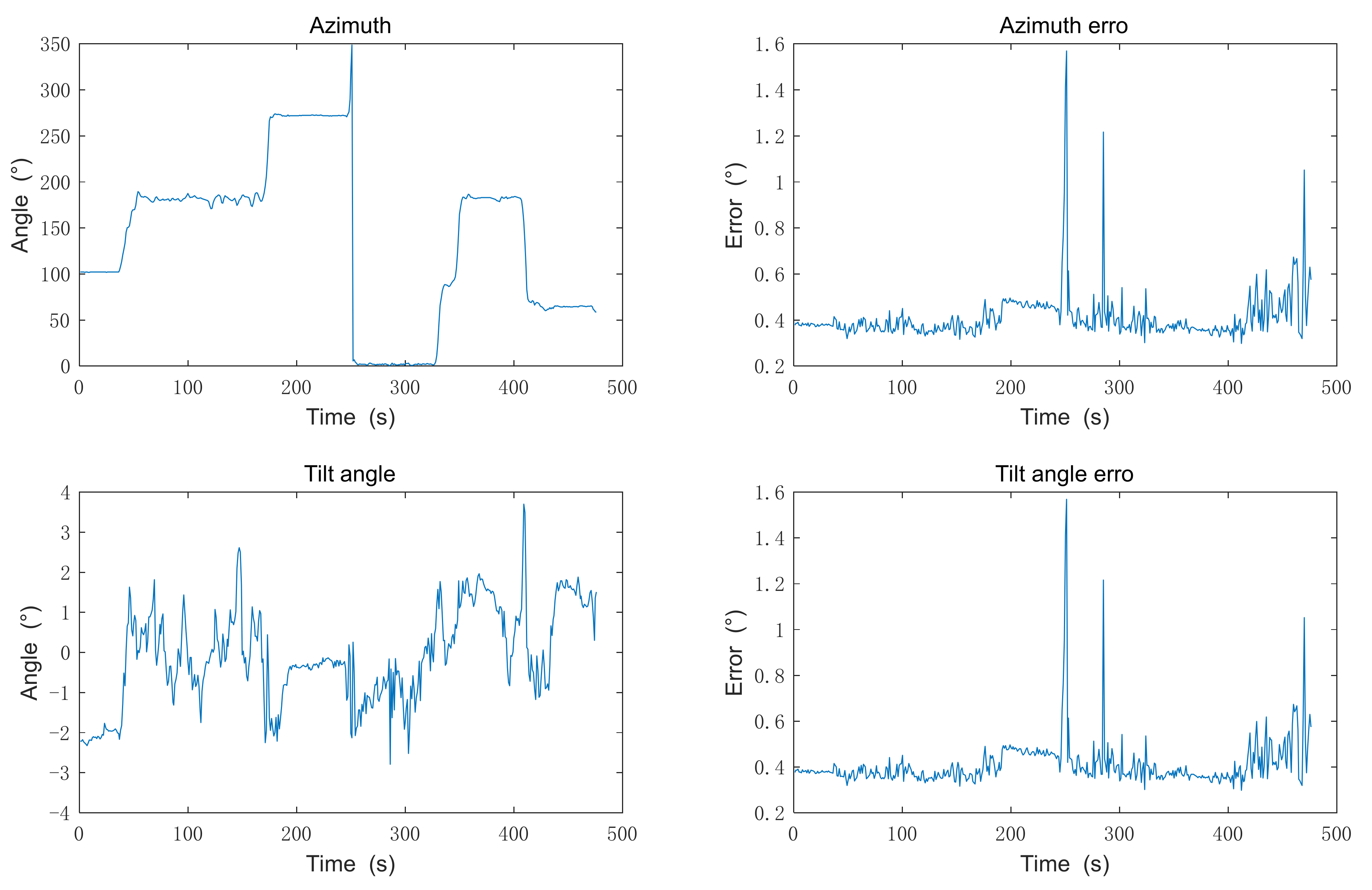
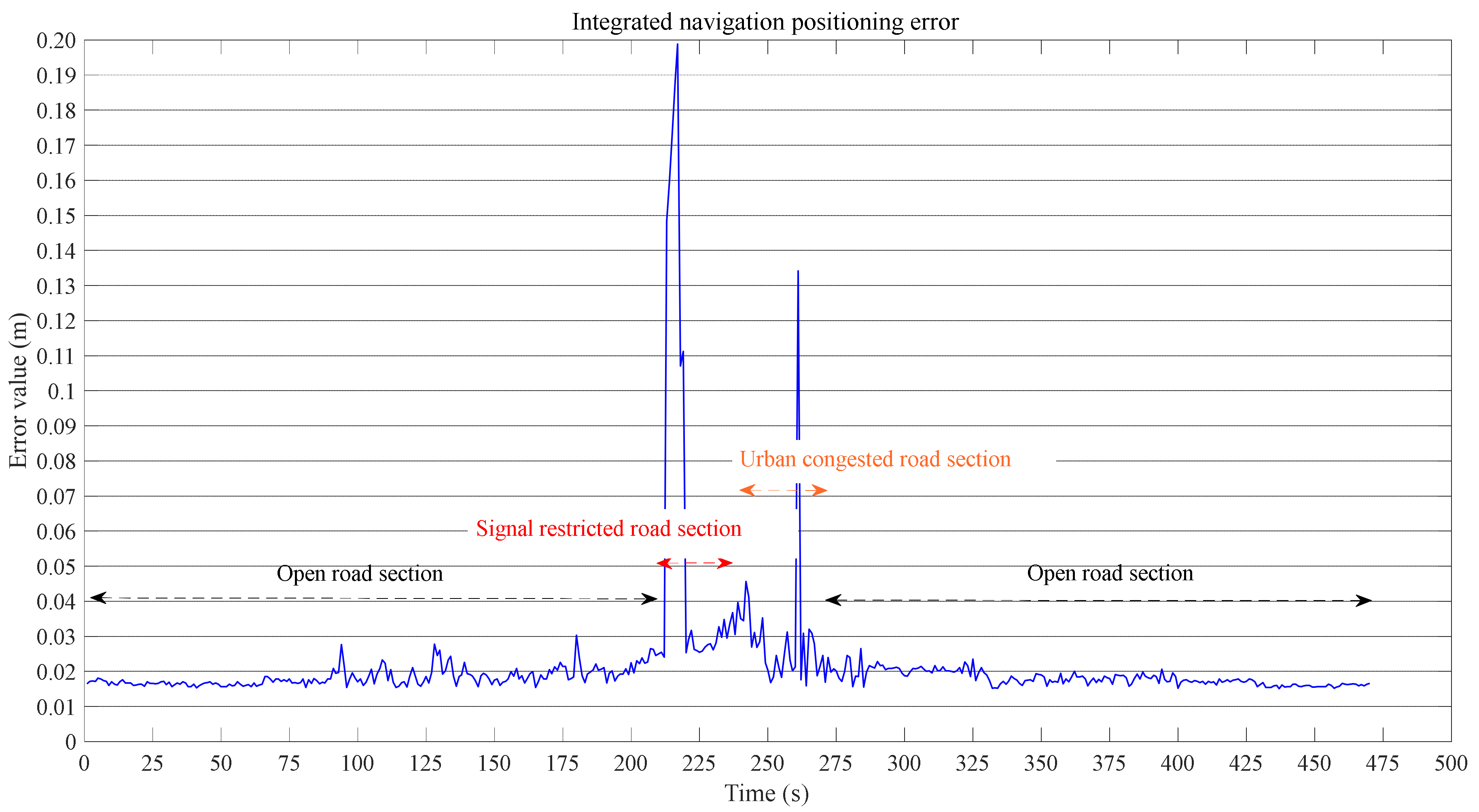
To test the working state of our system in the actual dynamic environment and ensure the reliability and accuracy of the system, this paper takes vehicles as the carrier to build a dynamic vehicle platform.
According to the principle of RTK positioning, the differential reference station adopts Sino navigation OEM board with built-in QT III SOC chip, which supports high-performance floating-point arithmetic, carries the k803 positioning module, and can receive BeiDou 2G and 3G satellite signals with a low power consumption of 1.0 W and a high data transfer rate of 20HZ.
The differential reference station adopts U70 data transmission module and LoRa protocol, which integrates receiving and transmitting functions, and is suitable for RTK real-time data transmission with stable output power, low power consumption and long transmission distance up to 10 km. Differential data can be transmitted to the vehicle-mounted mobile station.
The antennae used by the differential reference station are AT360W four-star all-frequency measurement antennae, supporting the reception of satellite signals of BDS, GPS, GLONASS and GALILEO mainstream navigation systems. The differential reference station is shown in Figure 5.
The vehicle-mounted mobile station also adopts OEM board, but equipped with K823 module high-precision positioning board, which supports BeiDou 2G and 3G satellite signals and double antenna signal input. The antenna model is also AT360W four-star full-frequency measuring antenna. The lost re-capture time is less than 1 s, the RTK initialization time is less than 5 s, and the data transfer rate is up to 50 HZ. Meanwhile, the integrated IMU high-precision inertial navigation device can measure the azimuth and inclination angle of the carrier. Through high data refresh rate and Kalman filter data fusion algorithm, continuous and high-quality positioning data can be provided even in the tunnel, buildings, forest and other satellite signal restricted environments. The vehicle-mounted mobile station is shown in Figure 6.

3.2. Experiment

The purpose of dynamic vehicle-mounted experiment is to test the positioning performance of navigation system in driving state of agricultural machinery. To deal with different situations that agricultural machinery may encounter during working and verify the reliability of the system design, we select the following route: north bank of Yongxing River–Sluice hub–Yongxing Avenue–City North Bridge–north bank of Yongxing River, among which the north bank of Yongxing River is an open road section that similar to general field, the Sluice hub is a signal-shielded road section to simulate the missing of BDS signals, and the Yongxing Avenue–City North Bridge is an urban congested road section to simulate the situation that agricultural machinery is affected by the noise of other machinery when executing multi-vehicle coordinated tasks. During the experiment, the weather was cloudy and the driving speed of agricultural machinery was 4 m/s.
During the experiment, the differential reference station was placed in an open environment on the north bank of Yongxing River, Fengtai County, Huainan City, Anhui Province. The U70 radio station of the differential reference station was set as the transmitting end of differential data, with a frequency of 460.05 MHZ and a power of 2 W.
The two AT360W four-star all-frequency measuring antennae were placed left and right on the top of the vehicle, with a baseline length of 0.88 m. The U70 wireless radio of the mobile station was set as the differential data receiving end, the frequency was set as 460.05 MHZ, and power was 2 W. When the IMU was in use, the y-axis marked by the IMU pointed to the vehicle moving direction.
The positioning data under the two modes of on and off of the integrated navigation were collected in the experiment, and the trajectory comparison results generated through data processing were shown in Figure 7. The black dashed line in the figure is the preset track route, and the green track line is the one measured when the integrated navigation mode was off. Some of the line segments are in yellow, which means that the satellite signals were poor and the position calculation results were inaccurate. The red track line is measured when the integrated navigation system was on with no inaccurate solution results, and is closer to the black reference line. The integrated navigation system test route is displayed on Google Maps through data processing, as shown in Figure 8.

4. Discussion

This experiment mainly deals with the positioning data of integrated navigation. In the ECEF (Earth-Centered Earth-Fixed) coordinate system, the z-axis and the Earth axis point parallel to the North Pole, the x-axis points to the intersection of the prime meridian and the equator, and the y-axis is perpendicular to the xOz plane (the intersection of East longitude 90 degrees and the equator). The position and velocity standard deviation on x-, y-, and z-axes can be obtained, as shown in Figure 9.
It can be seen from Figure 9 that the standard position deviation at the x-axis direction is lower than 0.04, and during most of the driving time, lower than 0.015. The standard deviation of speed is lower than 0.06. At the y-axis direction, the standard position deviation is lower than 0.06, and 0.02 in the majority of driving time, and the standard speed deviation is lower than 0.09. The standard deviation of position at the z-axis direction is lower than 0.05, and 0.02 during most driving time, and the standard speed deviation is lower than 0.06.
The data of azimuth angle and inclination angle are shown in Figure 10. The azimuth error during the most driving time in the figure is within 0.6°, with a large error of a few seconds, but remains within 1.6°; the deviation of inclination angle is within 1.4°, and remains within 1° most of the time. For some large errors, actual driving conditions are considered. For example, the 1.6° azimuth error because of the 350° sharp drop at the 250 s is considered as resulted from the large vehicle turning amplitude.
The integrated navigation system of agricultural machinery based on RTK-BDS/INS integrates RTK-BDS positioning data and IMU data to finally calculate the integrated navigation positioning error, as shown in Figure 11. The error is within 3 cm in the open road section of grassland with good satellite and radio signals, and no interference from tall obstacles. On the road sections with obscured signals and traffic congestion, satellite and radio signals will be interfered, and the errors will fluctuate greatly but within the allowable range. Moreover, the integrated navigation system has strong adaptive anti-interference ability, which can quickly correct the position information and reduce the error. Compared with previous research results, for example, in the tractor experiment in Literature 9, the lateral deviation of the integrated navigation system could only be kept within 10 cm at the speed of 3.33 m/s; the navigation system designed in Literature 25 could achieve an error within 6 cm when traveling at the speed of 1.5 m/s; the error of the autonomous navigation system designed in literature 23 could be controlled within the range of about 4 cm, but only at a speed of 0.3 m/s, the integrated navigation system designed in this paper is advantageous in following aspects: (1) the positioning accuracy can still be guaranteed at higher speeds without increase of error; (2) the mutual assistance of RTK-BDS and INS solves not only the problem that BDS signal may be interfered with transient loss of lock, but also the problem that error in single inertial navigation system will increase with time; using radio station to realize RTK technology avoids the high costs of network accounts purchase in the past, which is more in line with the actual needs of China.

5. Conclusions

In this paper, an integrated navigation system based on RTK-BDS/INS was designed to solve the problem of positioning accuracy of unmanned agricultural machinery. To combine the RTK technology with BDS to achieve centimeter-level precise positioning of agricultural machinery operation, a reference station based on k803 module positioning board card and a vehicle-mounted mobile station based on k823 module and IMU module board card were established. The data received by BDS and INS data were fused by Kalman filter algorithm.
The experimental results showed that the position error of the integrated navigation system could be less than 3 cm in the open agricultural machinery operating environment, the azimuth error could be less than 0.6°, and the inclination error less than 1°, which satisfies the precision requirements of agricultural machinery production. Even when dealing with signal interference, multi-machine cooperative operation, and other problems, the integrated navigation system still has good adaptive anti-interference ability and satisfactory positioning accuracy.

Author Contributions

Methodology, Y.H., J.F., S.X., and T.H.; conceived and designed the experiments, Y.H. and J.F.; performed the experiments, J.F. and Y.L.; analyzed the data, J.F.; wrote the paper, Y.H. and J.F.; funding acquisition, Y.H. All authors have read and agreed to the published version of the manuscript.

Funding

This research was funded by the National Natural Science Foundation of China, grant number 61772033 and Research and the Development Fund of Institute of Environmental Friendly Materials and Occupational Health, Anhui University of Science and Technology, grant number ALW2021YF03.

Institutional Review Board Statement

Not applicable.

Informed Consent Statement

Not applicable.

Data Availability Statement

The data that support the findings of this study are available on request from corresponding author.

Acknowledgments

The authors want to thank the editor and anonymous reviewers for their valuable suggestions for improving this paper.

Conflicts of Interest

The authors declare no conflict of interest.

References

  1. RShamshiri, R.; Weltzien, C.; Hameed, I.A.; JYule, I.; EGrift, T.; Balasundram, S.K.; Pitonakova, L.; Ahmad, D.; Chowdhary, G. Research and development in agricultural robotics: A perspective of digital farming. Int. J. Agric. Biol. Eng. 2018, 11, 1. [Google Scholar]
  2. Ayerdi Gotor, A.; Marraccini, E.; Leclercq, C.; Scheurer, O. Precision Farming Uses Typology in Arable Crop-Oriented Farms in Northern France. Precis. Agric. 2020, 21, 131–146. [Google Scholar] [CrossRef]
  3. Gebbers, R.; Adamchuk, V.I. Precision agriculture and food security. Science 2010, 327, 828–831. [Google Scholar] [CrossRef] [PubMed]
  4. Mungwongsa, A.; Saengprachatanarug, K.; Radpukdee, T. Design of an Automatic Steering System in a Small Farm Tractor. In Proceedings of the 2018 21st International Symposium on Wireless Personal Multimedia Communications (WPMC), Chiang Rai, Thailand, 25–28 November 2018; pp. 224–229. [Google Scholar]
  5. Yu, G.R.; Bai, K.Y.; Chen, M.C. Applications of Taguchi method to fuzzy control for path tracking of a wheeled mobile robot. In Proceedings of the 2018 IEEE International Conference on Applied System Innovation (ICASI), Chiba, Japan, 13–17 April 2018; pp. 453–456. [Google Scholar]
  6. Gao, F.Y.; Wang, Z.; Bai, X.P.; Xi, W.L. Design of Row Guidance Control System for Combine Corn Harvester. In Proceedings of the 2019 2nd International Conference on Information Systems and Computer Aided Education (ICISCAE), Dalian, China, 28–30 September 2019; pp. 354–358. [Google Scholar]
  7. Nam, K.; Oh, S.; Fujimoto, H.; Hori, Y. Robust yaw stability control for electric vehicles based on active front steering control through a steer-by-wire system. Int. J. Automot. Technol. 2012, 13, 1169–1176. [Google Scholar] [CrossRef]
  8. Takai, R.; Yang, L.L.; Noguchi, N. Development of a crowler-type robot tractor using RTK-GPS and IMU. Engineering in Agriculture. Environ. Food 2014, 7, 143–147. [Google Scholar]
  9. Backman, J.; Oksanen, T.; Visala, A. Navigation system for agricultural machines: Nonlinear model predictive path tracking. Comput. Electron. Agric. 2012, 82, 32–43. [Google Scholar] [CrossRef]
  10. Krüger, G.; Springer, R.; Lechner, W. Global navigation satellite systems (GNSS). Comput. Electron. Agric. 1994, 11, 3–21. [Google Scholar] [CrossRef]
  11. Ponnambalam, V.R.; Bakken, M.; Moore, R.J.D.; Gjevestad, J.G.O.; From, P.J. Autonomous Crop Row Guidance Using Adaptive Multi-ROI in Strawberry Fields. Sensors 2020, 20, 5249. [Google Scholar] [CrossRef]
  12. Titterton, D.H.; Weston, J.L. Strapdown Inertial Navigation Technology Aerospace & Electronic Systems Magazine; IEEE: Piscataway, NJ, USA, 2004. [Google Scholar] [CrossRef]
  13. Tazartes, D. An historical perspective on inertial navigation systems. In Proceedings of the 2014 International Symposium on Inertial Sensors and Systems (ISISS), Laguna Beach, CA, USA, 25–26 February 2014; pp. 1–5. [Google Scholar]
  14. Qin, Y.-Y. Inertial Navigation; Science Press: Beijing, China, 2006. [Google Scholar]
  15. Draper, C. Control, navigation and guidance. IEEE Control Syst. Mag. 1981, 1, 4–17. [Google Scholar] [CrossRef]
  16. Li, K.; Gao, P.Y. Research on self-calibration technique for hybrid inertial navigation system. Chin. J. Sci. Instrum. 2019, 40, 9–17. [Google Scholar]
  17. Li, J.; Guo, S.; Cui, G.; Chen, C. Polar underwater calibration for strapdown inertial navigation system. Chin. J. Sci. Instrum. 2018, 39, 51–58. [Google Scholar]
  18. Zhang, M.; Ji, Y.; Li, S.; Cao, R.; Xu, H.; Zhang, Z. Research Progress of Agricultural Machinery Navigation Technology. Trans. Chin. Soc. Agricult. Machin. 2020, 51, 1–18. [Google Scholar] [CrossRef]
  19. Wang, T.; Chen, B.; Zhang, Z.; Li, H.; Zhang, M. Applications of machine vision in agricultural robot navigation: A review. Comput. Electron. Agric. 2022, 198, 107085. [Google Scholar] [CrossRef]
  20. Landau, H.; Chen, X.; Klose, S.; Leandro, R.; Vollath, U. Trimble’s RTK and DGPS solutions in comparison with precise point positioning, observing our changing earth. In Proceedings of the International association of Geodesy Symposia, Perugia, Italy, 2–13 July 2007; pp. 709–718. [Google Scholar]
  21. Groves, P.D.; Wang, L.; Walter, D.; Martin, H.; Voutsis, K.; Jiang, Z. The four key challenges of advanced multisensor navigation and positioning. In Proceedings of the IEEE/ION PLANS, Monterey, CA, USA, 5–8 May 2014; pp. 773–792. [Google Scholar]
  22. Li, X.; Wang, X.; Liao, J.; Li, X.; Li, S.; Lyu, H. Semi-tightly coupled integration of multi-GNSS PPP and S-VINS for precise positioning in GNSS challenged environments. Satell. Navig. 2021, 2, 1. [Google Scholar] [CrossRef]
  23. Bakker, T.; van Asselt, K.; Bontsema, J.; Müller, J.; van Straten, G. Autonomous navigation using a robot platform in a sugarbeet field. Biosyst. Eng. 2011, 109, 357–368. [Google Scholar] [CrossRef]
  24. Maseila, E.; Gonthier, M.; Dumaine, M. Precise kinematic positioning experimentswith a low-cost RTK GPS engine. In Proceedings of the IEEE 1998 Position Location and Navigation Symposium, Palm Springs, CA, USA, 20–23 April 1998; pp. 250–255. [Google Scholar]
  25. Kise, M.; Noguchi, N.; Ishii, K.; Terao, H. Development of agricultural autonomous tractorwith an RTK-GPS and a FOG. In Proceedings of the IFAC Proceedings Series, Berkeley, CA, USA, 9–11 December 2002; pp. 99–104. [Google Scholar]
  26. Zhang, M.; Yin, W.L.; Lin, X.; Lü, X. Method for Calculating Navigation Parameter Via RTK-DGPS Fusing Inertial Sensor for Agricultural Vehicle. Trans. Chin. Soc. Agric. Mach. 2015, 40, 7–12. [Google Scholar]
  27. Yuan, Y.; Mi, X.; Zhang, B. Initial assessment of single- and dual-frequency BDS-3 RTK positioning. Satell Navig. 2020, 1, 37. [Google Scholar] [CrossRef]
  28. Zhao, Q.; Guo, J.; Wang, C.; Lyu, Y.; Xu, X.; Yang, C.; Li, J. Precise orbit determination for BDS satellites. Satell Navig. 2022, 3, 2. [Google Scholar] [CrossRef]
  29. Zhang, Y.; Kubo, N.; Chen, J.; Wang, J.; Wang, H. Initial Positioning Assessment of BDS New Satellites and New Signals. Remote Sens. 2019, 11, 1320. [Google Scholar] [CrossRef] [Green Version]
  30. Pan, L.; Li, X.; Yu, W.; Dai, W.; Kuang, C.; Chen, J.; Chen, F.; Xia, P. Performance Evaluation of Real-Time Precise Point Positioning with Both BDS-3 and BDS-2 Observations. Sensors 2020, 20, 6027. [Google Scholar] [CrossRef]
  31. Xiong, B.; Zhang, J.; Qu, F.; Fan, Z.; Wang, D.; Li, W. Navigation Control System for Orchard Spraying Machine Based on Beidou Navigation Satellite System. Trans. Chin. Soc. Agric. Mach. 2017, 48, 45–50. [Google Scholar]
  32. Wang, J.; Zhao, B.; Zhao, S.; Xing, G.; Wei, L.; Hu, X. Design and test of the BDS navigation system for trenchless pipe laying machines. Trans. Chin. Soc. Agric. Eng. (Trans. CSAE) 2021, 37, 47–54. (In Chinese) [Google Scholar] [CrossRef]
  33. Sun, H.; Slaughter, D.C.; Ruiz, M.P.; Gliever, C.; Upadhyaya, S.K.; Smith, R.F. RTK GPS mapping of transplanted row crops. Comput. Electron. Agric. 2010, 71, 32–37. [Google Scholar] [CrossRef]
  34. Gan-Mor, S.; Clark, R.L.; Upchurch, B.L. Implement lateral position accuracy under RTK-GPS tractor guidance. Comput. Electron. Agric. 2007, 59, 31–38. [Google Scholar] [CrossRef]
  35. Bell, T. Automatic tractor guidance using carrier-phase differential GPS. Comput. Electron. Agric. 2000, 25, 53–66. [Google Scholar] [CrossRef]
  36. Ashby, N. Relativity in the Global Positioning System. Living Rev. Relativ. 2003, 6, 1. [Google Scholar] [CrossRef] [Green Version]
Figure 1. RTK working principle.
Agriculture 12 01169 g001
Figure 2. Simplified schematic of inertial navigation.
Agriculture 12 01169 g002
Figure 3. Integrated navigation system structure.
Agriculture 12 01169 g003
Figure 4. Flowchart of integrated navigation system.
Agriculture 12 01169 g004
Figure 5. Differential reference station.
Agriculture 12 01169 g005
Figure 6. Vehicle-mounted mobile station.
Agriculture 12 01169 g006
Figure 7. Comparison of two navigation modes.
Agriculture 12 01169 g007
Figure 8. Real environment roadmap.
Agriculture 12 01169 g008
Figure 9. Analysis in ECEF coordinate system.
Agriculture 12 01169 g009
Figure 10. Angles and errors.
Agriculture 12 01169 g010
Figure 11. Integrated navigation positioning error.
Agriculture 12 01169 g011
Publisher’s Note: MDPI stays neutral with regard to jurisdictional claims in published maps and institutional affiliations.

