Article

Design of Hydrostatic Chassis Drive System for Large Plant Protection Machine

1
School of Mechanical Engineering, University of Jinan, Jinan 250022, China
2
School of Mechanical and Automotive Engineering, Qilu University of Technology (Shandong Academy of Sciences), Jinan 250353, China
3
Shandong Huasheng Zhongtian Machinery Group Co., Ltd., Linyi 276000, China
*
Author to whom correspondence should be addressed.
Agriculture 2022, 12(8), 1118; https://doi.org/10.3390/agriculture12081118
Submission received: 20 June 2022 / Revised: 20 July 2022 / Accepted: 25 July 2022 / Published: 29 July 2022

Abstract

:
In order to meet the working performance of large plant protection machine and according to the actual working requirements, this paper proposes a design of hydrostatic chassis drive system for a large plant protection machine. The purpose of this study is to realize the anti-slip rotation function of the plant protection machine and improve the driving stability through the combination of a hydraulic drive system and shunt valve. In this study, a closed circuit with a single pump and four motors is used, and a diverter valve is used to prevent the wheels from skidding during the driving of the plant protection machine. The parameters of the main hydraulic components of the hydraulic drive system were firstly calculated and selected; then the AMESim software was used to model and simulate the hydraulic drive system. Finally, a test platform with anti-skid function is designed and built, and the test results are as follows: when the diverter valve is closed, the plant protection machine drives at 3 km/h and 6 km/h respectively, and the skid rate is 3.79% and 6.17%; when the diverter valve is open, the plant protection machine drives at 3 km/h and 6 km/h respectively, and the skid rate is 1.33% and 2.70% respectively. The test results show that the hydraulic chassis of the plant protection machine designed in this study has good driving stability and can effectively reduce the slip rate of the plant protection machine in the process of driving in the field, which provides an effective theoretical support for the design of the driving system of the hydraulic chassis of the plant protection machine.

1. Introduction

In order to rapidly develop the mechanization level of China’s field management equipment, improve the production conditions of field operations, and improve work efficiency, it is necessary to develop and produce the hydraulic chassis of plant protection machines suitable for fields [1,2]. Because the working environment of the plant protection machine is mainly in the field, it is easy to slip during the operation, which affects the operation of the driver. Therefore, it is of great significance to develop the hydraulic chassis of the plant protection machine with anti-slip function to improve its driving stability [3,4]. The hydraulic system is one of the most important energy sources designed by humans—it converts mechanical energy into hydraulic energy, it is widely used in high-performance equipment applications that require fast response and high power [5,6]. Hydraulic systems are widely used in the walking systems of construction machinery and agricultural machinery [7,8]. It is suitable for sites with complex road conditions and working environments [9,10,11]. As the main transmission mode of the hydraulic system, by dynamically adjusting the parameters of the pump and motor, the vehicle can move forward and backward, and functions such as speed regulation and load adaptation can be accomplished [12,13]. Compared with mechanical transmission, machine–hydraulic transmission and hydraulic transmission, hydraulic transmission has the advantages of flexible layout, easy realization of stepless speed regulation, and convenient intelligent control [14,15]. It has good adaptability to agricultural equipment, so the selection of hydraulic transmission as the driving mode of the plant protection machine chassis is of great significance to the driving stability of the plant protection machine [16].
In recent years, the research on agricultural machinery technology and the research and development of agricultural equipment have been the focus, especially the design of the chassis drive system [17]. Li Jiaxue et al. [18] In view of the traditional orchard transporter transmission system and the realization of stepless variable speed structure complex and other problems, the design of the hydraulic drive chassis of the orchard transporter that can be quickly reversed, stepless speed regulation, instantaneous braking, the design of the hydraulic system can simulate the actual operation process of the orchard transporter when different load states up, stop and down, verify the feasibility of the hydraulic system, so that the trailer at 0.71 m/s speed uniform motion, meeting the expected design requirements at 0.7 m/s and satisfying the power and transport speed requirements of the transporter. Nie Yuanyuan et al. [19] In order to solve the problems of large damage to seedlings, complex transmission and large turning radius when the spraying machine is walking in the field, a special chassis for rice agronomy is designed, and the smooth transmission of the spraying machine is tested through the test, and the seedling loss rate is less than 3%; and the minimum turning radius is 3.12 m after optimization, which realizes the damage to crops for the reduction of turning radius. Hu Kai et al. [20,21] To solve the adaptation problem of traditional tractors in hilly mountainous areas, a technical solution of a fully hydraulic chassis drive system is proposed, and the results show that the working pressure, output torque and output speed are very demanding on the motor performance. When the synchronous motor is not working, one of the wheels will slip leading to the loss of driving capacity working pressure is only 1.838 MPa, if the synchronous motor is forced to shunt in this position, the required working pressure is 19.197 MPa to make the machine resume exercising capacity. Companies, such as CNH, AGCO, John Deere, AGRIO, HAGIE and DAMMANN, have been taking the upland gap self-propelled plant protection machine as an important product of its research and development [22]. The US John Deere developed the 4730 series sprayer, which uses a variable motor-variable pump four-wheel fully hydraulic drive system and a multi-mode steering hydraulic system to reach a leading position in the field [23].
In summary, aiming at a situation in which the wheels of the plant protection machine are prone to slip when working in the field, a walking hydraulic system is designed that considers the driving stability of the hydraulic chassis of the plant protection machine. The simulation analysis of the anti-skid rotation condition of the walking hydraulic system is carried out through the AMESim software to verify the feasibility of the hydraulic system. Finally, the anti-skid rotation test is carried out through the test platform, which further verifies the driving stability of the hydraulic chassis of the plant protection machine designed in this paper.

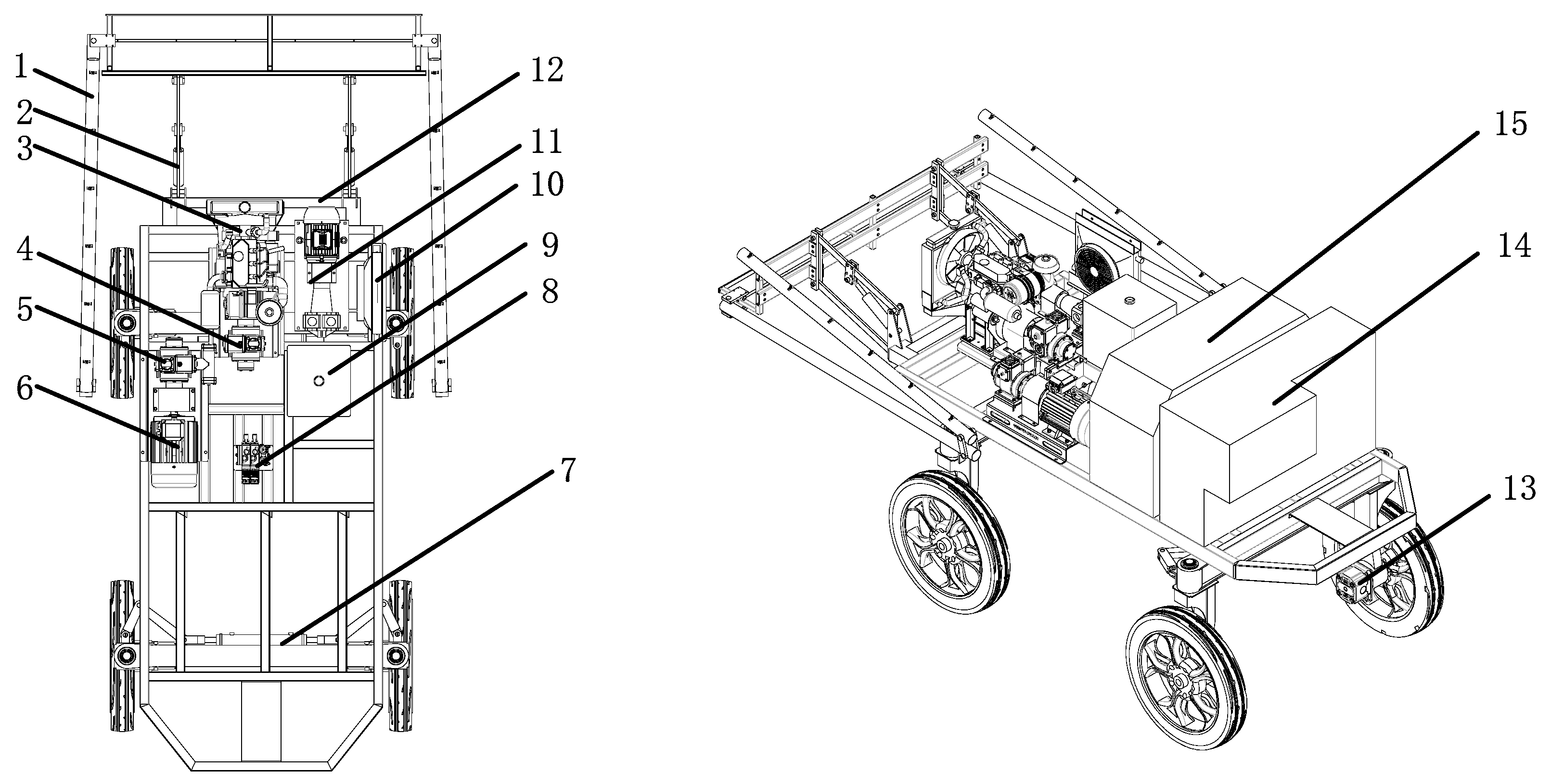
2. Design of Hydraulic Chassis Structure and Scheme

The hydraulic chassis structure of the plant protection machine is shown in Figure 1, which is mainly composed of a driving device, a rear suspension device, an energy device and a medicine box. The driving device mainly includes diesel engine, frequency conversion motor, hydraulic pump, hydraulic motor, reversing valve group, driving wheel and other structures. The rear suspension device mainly includes the lifting frame, spray boom and other structures. The energy device mainly includes a hydraulic oil tank and a large battery. In order to ensure the balance of the front and rear ends of the chassis and prevent the occurrence of backward tilt, the spray suspension device and the engine, frequency conversion motor, fuel tank and other devices are installed at the rear, and the medicine box, battery and other devices are installed in the front, so that the center of mass of the whole machine reaches a balanced state. The main design parameters of the plant protection machine are shown in Table 1.
The plant protection machine mainly includes two sets of power units: The power unit with the engine as the power source and the piston variable pump combination; the power unit with the variable frequency motor as the power source and the piston variable pump combination. The plant protection machine mainly adopts the drive scheme of single pump and four motors and adopts the diverter valve to prevent the hydraulic motors in parallel from slipping. The forward, backward, acceleration, deceleration, stop and other actions of the plant protection machine are mainly completed by the action of the hydraulic pump to change its own displacement and the direction of the swash plate.

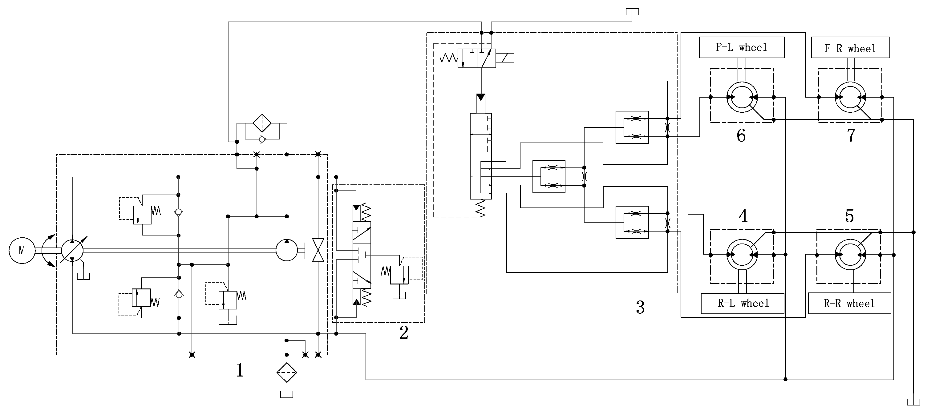
2.1. Design of the Hydraulic System

The hydrostatic chassis of the plant protection machine mainly transmits power and controls through the hydraulic pump hydraulic motor. This paper only needs to design the hydraulic drive system of the plant protection machine, and only provide the corresponding hydraulic interface for the lifting and wheel steering systems of the rear suspension machine. For plant protection machines, hydraulic drive has the characteristics of high transmission efficiency, wide speed regulation range, good low speed performance, and stepless speed regulation [24,25,26,27].
The plant protection machine mainly adopts a hydraulic closed circuit, As shown in Figure 2. The hydraulic pump and the hydraulic motor are connected in parallel in the hydraulic circuit, and the inlet and outlet pressure of the hydraulic pump can change with the change of the system pressure. In a closed loop, the motor can be regulated without a reversing valve, which has the characteristics of high transmission efficiency, fast response speed, and simple control [28,29]. For the plant protection machine, the speed and direction need to be adjusted at any time during the working process of the plant protection machine, and it is required to have good speed rigidity and corresponding speed, and the closed loop can accurately meet this demand.
The working principle of the hydraulic system of the plant protection machine: Use the engine (or variable frequency motor) as the power source to supply oil for the variable pump (main pump, charge pump). The variable pump is used as the input element to transmit the oil to the four wheel motors through the diverter valve, so that the plant protection machine can complete the actions of forward, backward, acceleration and deceleration. The variable pump and the wheel motor are connected end to end to form a closed circuit. Most of the oil flows into the variable pump return port through the oil return circuit, and a small part returns to the mailbox through the flush valve. The variable pump is a plunger variable pump, which can adjust the driving speed and direction of the plant protection machine by changing its own displacement and the direction of the swash plate. When the plant protection machine is running normally, the control valve of the diverter valve group will not be powered, the diverter valve will not work, and the system flow will be automatically allocated according to the needs of the executive components; When one or more wheels of the plant protection machine slip, the control valve of the diverter valve group is energized, and the diverter valve works, so that the flow in the hydraulic system flows evenly through the hydraulic motor to make it rotate synchronously. The main function of the charge pump is to supplement the leakage of oil in the closed circuit, while the charge pressure in the system avoids cavitation of hydraulic components. The main function of the flush valve is to discharge the heat and contaminants in the main circuit faster and prevent the closed oil circuit from causing the hydraulic oil temperature to rise.

2.2. Calculation and Selection of Hydraulic System

2.2.1. Calculation of Hydraulic System

The driving force of the plant protection machine is transmitted from the torque output by the engine (frequency conversion motor) to the hydraulic motor through the hydraulic circuit, and the hydraulic motor finally achieves the state of driving the wheels to rotate. During the driving process, the plant protection machine must overcome the rolling resistance Ff from the ground, and the rolling resistance is the normal interaction force generated by the contact area between the tire and the road surface; the air resistance Fw received during the driving process, the air resistance is the component force of the air force in the driving direction when the vehicle is running in a straight line; the plant protection machine overcomes the component gradient resistance Fi of its own gravity along the slope during the uphill process, acceleration resistance Fj when moving forward, the acceleration resistance is the inertial force when the vehicle moves against the acceleration of its mass; Ft is the tractive force of the plant protection machine [30,31,32,33,34]. At this time, the plant protection machine should meet the following stress conditions:
F t = F = F f + F w + F i + F j .
The working site of the plant protection machine is mainly cultivated land, and the slope is small and relatively small, so the value of the slope is selected as 20°. The plant protection machine is mainly used for soybeans, wheat, corn and other crops growing in the early stage, so during the driving process, the speed generally does not exceed 10 km/h, so the air resistance Fw and Fj and acceleration resistance are ignored. In order to ensure the safety of the plant protection machine during driving, the driving force of the plant protection machine needs to be greater than the driving resistance and not exceed the adhesion of the plant protection machine. Table 2 shows the rolling resistance coefficient f and adhesion coefficient under different environments φ.
The maximum driving resistance of the plant protection machine is ∑F, and the adhesion is Fφ:
F = F f + F i .
The driving resistance Ff is calculated as:
F f = f G cos α .
In Formula (3), f is the rolling resistance coefficient. Since the working site of the plant protection machine is mainly dry fields, the value of f is 0.15; G is the weight of the plant protection machine when it is fully loaded, 19,600 N.
When the plant protection machine travels on a normal road, its slope angle is not large, cosα ≈ 1.
The slope resistance Fi is calculated as:
F i = G cos α .
In Formula (4), α is the slope angle, 20°.
The calculation method of the adhesion force Fφ is:
F φ = G φ .
In Formula (5), φ is the adhesion coefficient, 0.6.
The maximum running resistance ∑F = 8012 N and the adhesion force Fφ = 11,760 N are obtained by the above formula. The adhesion is greater than the maximum driving resistance, so that the plant protection machine has sufficient grip.

2.2.2. Selection of Hydraulic Motor

The plant protection machine adopts the drive scheme of single pump and four motors, and the weight of the whole machine is about 19,600 N. Assuming that the driving wheel has the same load when the plant protection machine is running, the output torque of each wheel motor can be obtained:
M m = F t R N η m .
In Formula (6), Ft is the traction force, 8012 N; R is the radius of the driving wheel, 0.470 m; N is the number of driving wheels, 4; ηm is the mechanical efficiency (considering the slip), 0.96.
The output torque of the wheel motor can be obtained as 980 N·m, so the displacement of the wheel motor can be obtained. The displacement formula of the wheel side hydraulic motor is:
M = 2 π M m Δ P η m m .
In Formula (7), Δ P is the pressure difference between the inlet and outlet of the wheel motor, 20 Mpa; η m m is the mechanical efficiency of the wheel motor, 0.95.
The output flow of the wheel hydraulic motor is:
q 0 = n 0 V η v .
In Formula (8), n0 is the maximum speed of the motor when the plant protection machine is working, 40 r/min; ηv is the volumetric efficiency of the hydraulic motor, 0.95.
The calculated displacement of the motor is 344 mL/r. According to the above calculation, combined with the selection principle of the hydraulic motor, the axial piston motor with a displacement of 417.3 mL/r from Japanese manufacturer Fujitsu was finally selected, and the model is PHV-1B-12B-8502A. The motor parameters are shown in Table 3.

2.2.3. Selection of Hydraulic Pump

The walking hydraulic system of the plant protection machine adopts a closed hydraulic system. When leakage is not considered, the flow of the hydraulic pump flows out from the oil outlet, all flows into the hydraulic motor, and finally flows in through the oil return port of the hydraulic pump. The total flow of the hydraulic pump is:
Q = 4 q 0 .
The displacement of the hydraulic pump is:
Q = Q   n η v p   .
In Formula (10), n is the engine speed, 3000 r/min; ηvp is the volumetric efficiency of the hydraulic pump, 0.95.
The displacement of the hydraulic motor was calculated to be 19 mL/r. According to the above calculation, combined with the selection of hydraulic pump, the DDC20 axial piston variable pump with a displacement of 20 mL/r from Danfoss was finally selected, and the displacement of the built-in charge pump was 4.8 mL/r. The hydraulic pump parameters are shown in Table 4.

3. Simulation of the Walking Hydraulic System

In order to verify the reasonable performance of the hydraulic system design, a hydraulic drive system simulation model was established based on the AMESim simulation software. Simulation steps: (1) Select the corresponding modeling components of the mechanical library, signal control library, hydraulic library, and hydraulic component design library to connect them to build a simulation model sketch; (2) Select the appropriate sub-model for the sketch component in the sub-model setting; (3) In the parameter mode, set parameters for each hydraulic component; (4) Set the simulation step size and simulation time to simulate.

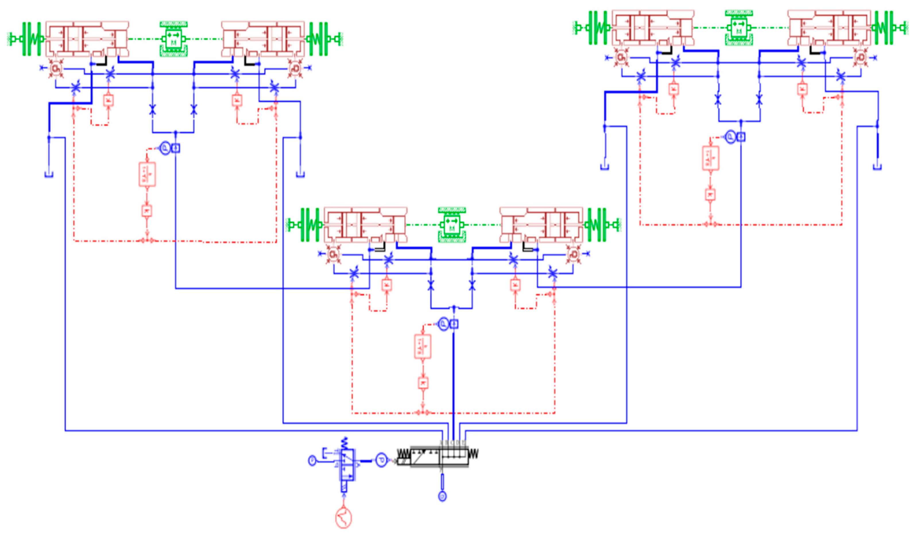
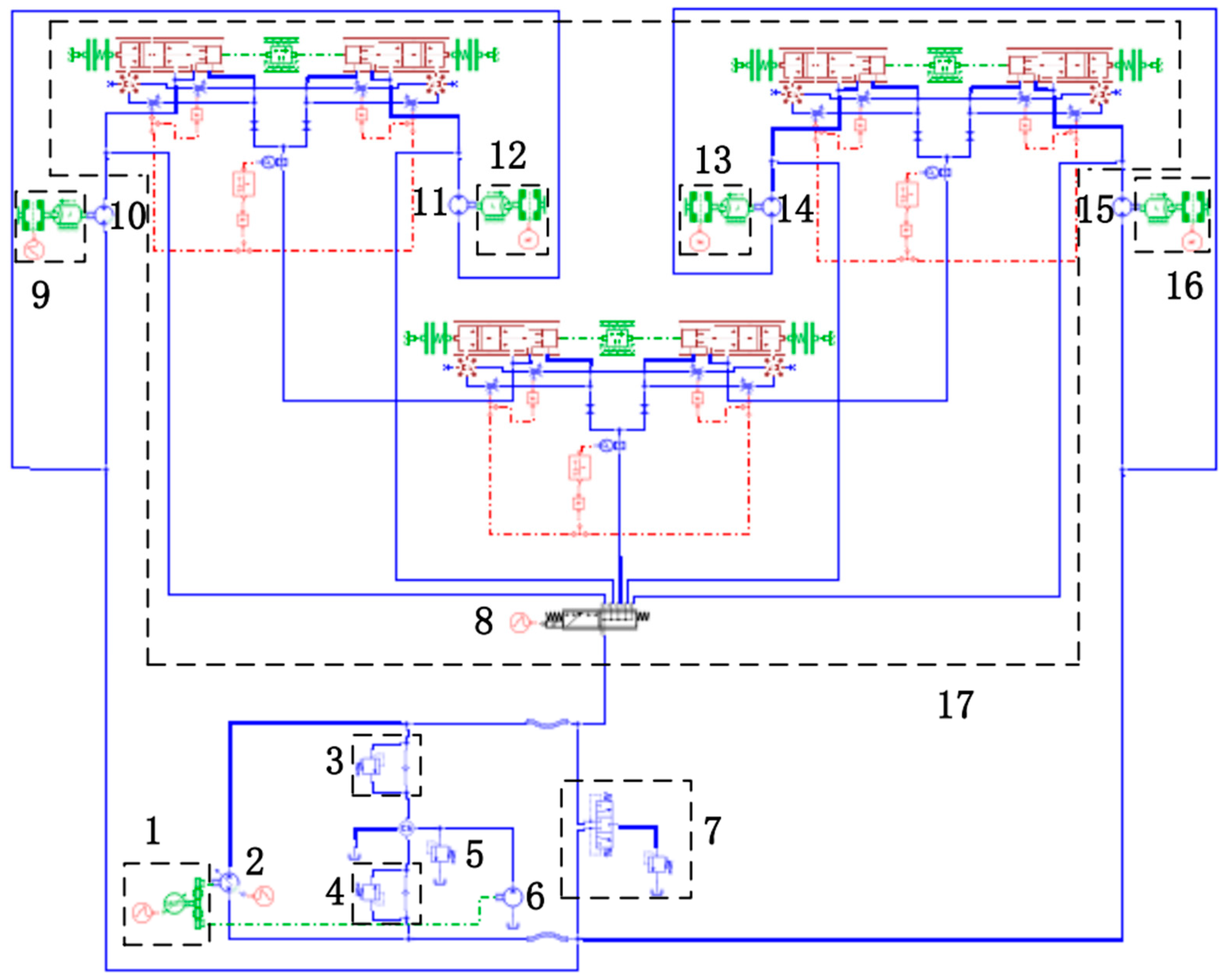
3.1. Establishment of Hydraulic System Simulation Model

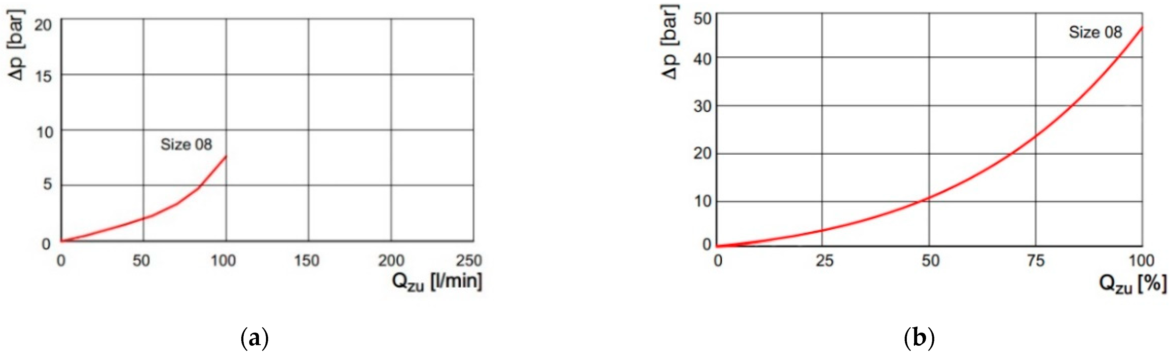
3.1.1. Establishment of the Diverter Valve

According to the internal structure of the diverter valve, the oil flow direction and the flow-pressure trend curve of the diverter valve, in order to make it have a better simulation effect, the hydraulic design element is used to model the diverter valve. The simulation modeling of the diverter valve in AMESim is shown in Figure 3.
Figure 4 is the flow-pressure curve of the diverter valve sample, and Figure 5 is the flow–pressure curve of the diverter valve model built using the hydraulic component library. (a) is the flow–pressure trend curve when the diverter valve is de-energized, and (b) is the flow–pressure trend curve when the diverter valve is energized. It is observed that the flow–pressure trend curve of the diverter valve model is approximately consistent with the flow–pressure trend curve of the diverter valve given by the sample.

3.1.2. Establishment of Simulation Model of Walking Hydraulic System

The model established in AMESim for the schematic diagram of the walking hydraulic system is shown in Figure 6.
During the driving process of the plant protection machine, a single or multiple tires will slip, which will affect the driving of the plant protection machine. At this time, it is necessary to open the diverter valve to divert the hydraulic system, so that the four wheel hydraulic motors can obtain the same flow. Continue move forward to get the plant protection machine out of the slipping state. This paper mainly simulates the following three working conditions of the plant protection machine: (1) the simulation time is 10 s, and the simulation step is set to 0.01 s. When the plant protection machine is running normally, observe the changes in the speed, torque and flow of the hydraulic motor at the wheel; (2) the simulation time is 10 s, and the simulation step is set to 0.01 s. During the driving process of the plant protection machine, any wheel slips, and the rotation speed, torque and flow of the hydraulic motor around the wheel are observed; (3) the simulation time is 10 s and the simulation step is set to 0.01 s. The wheel of the plant protection machine slips within 0~5 s. Within 5~10 s, the diverter valve is opened to divert the flow, and the speed, torque and flow rate of the hydraulic motor at the wheel side are observed. The main simulation parameters of the hydraulic system are shown in Table 5:

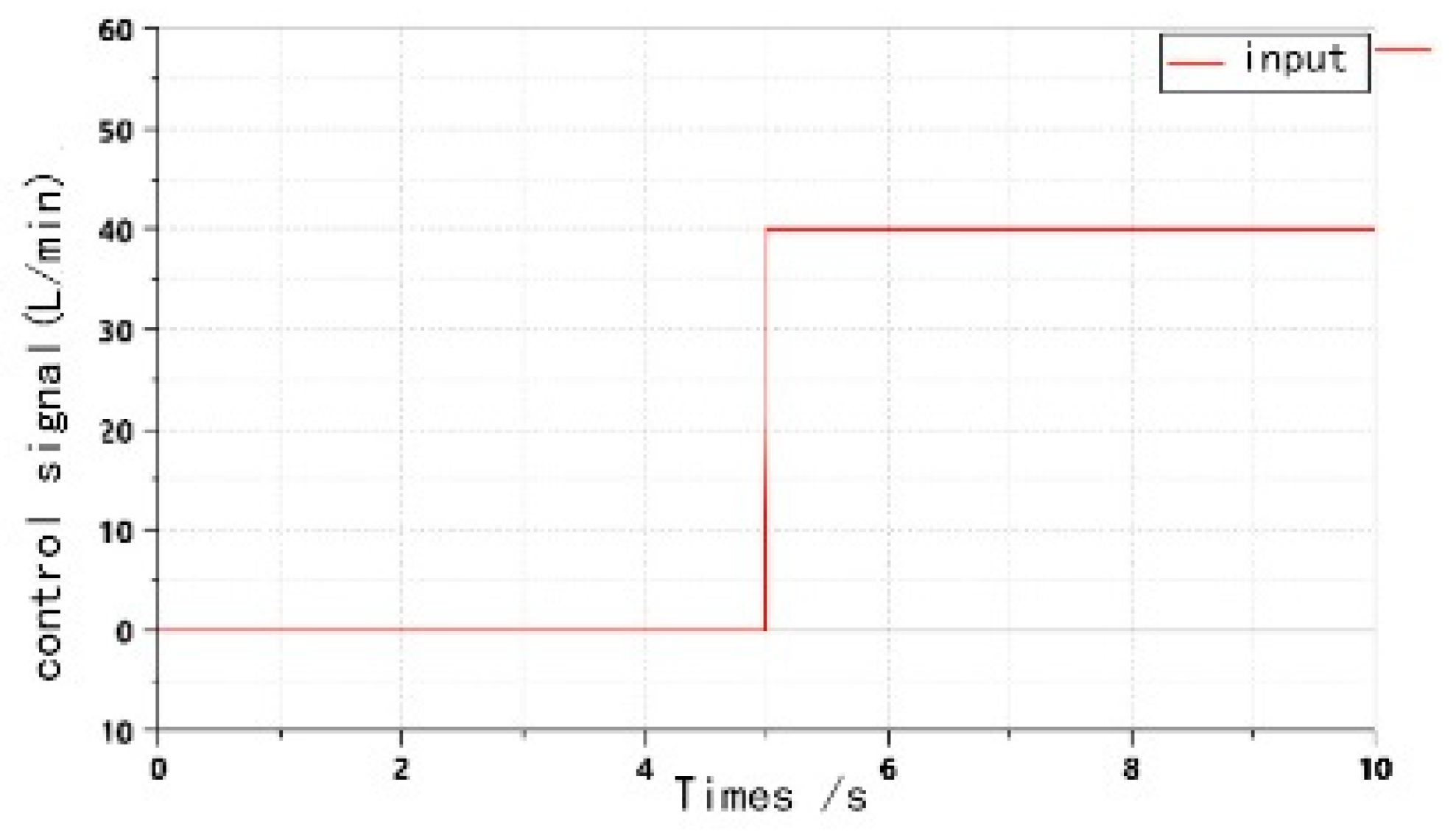
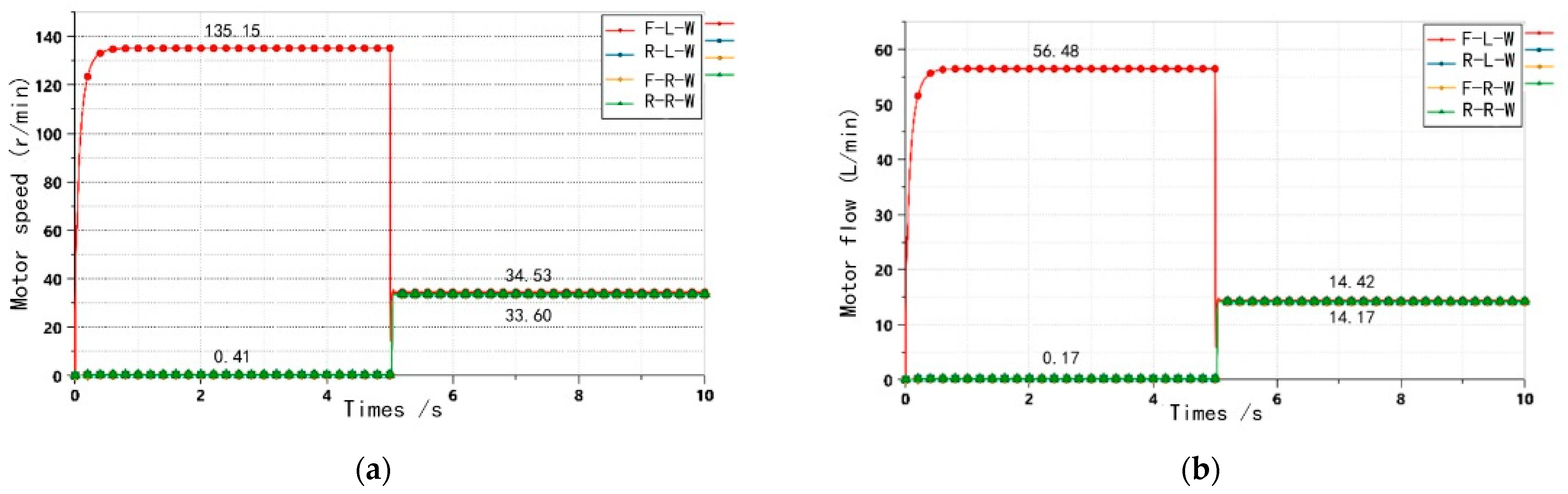
3.2. Analysis of Simulation Conditions

Working condition 1: The output loads of the four hydraulic motors are all 980 N m, as can be seen from Figure 7a,b. When the hydraulic system starts, the motor speed and flow fluctuate, which is caused by the shock and component inertia when the hydraulic system starts, and then the wheel-side hydraulic motor speed and flow eventually tend to be stable. When the hydraulic chassis is fully loaded, the wheel-side hydraulic motor speed is finally 33.80 r/min, and the hydraulic motor flow is finally 14.25 L/min.
Working condition 2: The output load of the slip hydraulic motor is set to 10 N·m, and the output load of the other hydraulic motors is 980 N·m. It can be seen from Figure 8a,b that when the hydraulic chassis is running, slip occurs, and the flow output from the hydraulic pump all flows into the slip hydraulic motor. At this time, the load pressure of the slip hydraulic motor is the smallest, the speed reaches the maximum, and the speed is finally 135.15 r/min, the flow reaches the maximum, and the flow is finally 56.47 L/min. The movement state of the hydraulic chassis is that the single wheel loaded by the slipping hydraulic motor rotates alone, and the hydraulic motors around the other wheels are in a static state due to the large load, thus causing the hydraulic chassis to stop moving forward.
Working condition 3: The output load of the slip hydraulic motor is set to 10 N·m, and the output load of the other hydraulic motors is 980 N·m. Within 0~5 s, the diverter valve is powered off, and the hydraulic chassis is in a slipping state. In 5~10 s, the diverter valve is energized to divert the total flow of the hydraulic system. The hydraulic chassis leaves the slipping state and starts to move. The diverter valve signal input is shown in Figure 9. Since the diverter valve has an allowable value of 5%~10% diversion error, there will be a slight difference in the speed of the wheel motor of the hydraulic chassis.
Now it is proposed that the left front wheel of the hydraulic chassis slips. It can be seen from Figure 10a,b that within 0~5 s, the diverter valve is powered off, the hydraulic chassis slips, and the left front wheel gets most of the flow, thus causing high-speed rotation. At this time, the hydraulic motor speed of the left front wheel can reach up to 135.15 r/min, and the flow rate can reach up to 56.47 L/min. Within 5~10 s, the diverter valve is energized, the flow of the four wheel hydraulic motors is evenly divided, and the three wheel motors except the left front wheel can rotate normally. The rotation speed of the four wheel hydraulic motors is basically the same. Between 33.60 r/min and 34.53 r/min, the input flow is between 14.17 L/min and 14.42 L/min, so the hydraulic chassis can run normally.

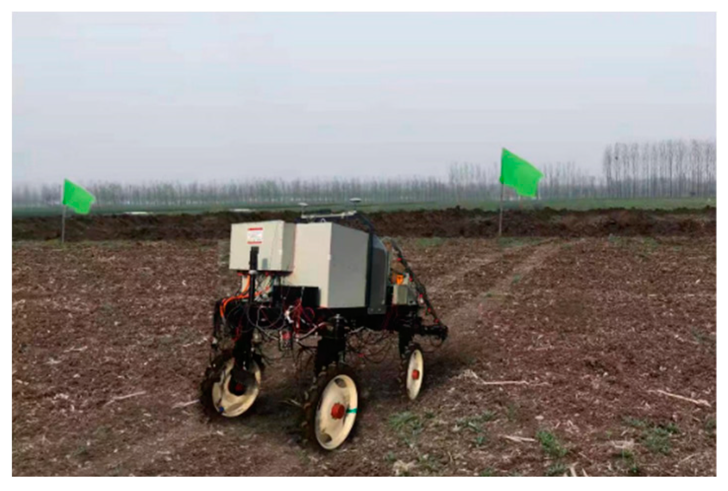
4. Experimental Design and Analysis

The field test is carried out on the four-wheel drive hydraulic chassis of the plant protection machine, and the anti-slip test is carried out during the driving process of the plant protection machine. The driving stability of the hydraulic chassis was analyzed, the theoretical driving distance and the actual driving distance were measured, the slip rate during the driving process of the hydraulic chassis was calculated, and the anti-slip performance was evaluated. The anti-slip test is shown in Figure 11.

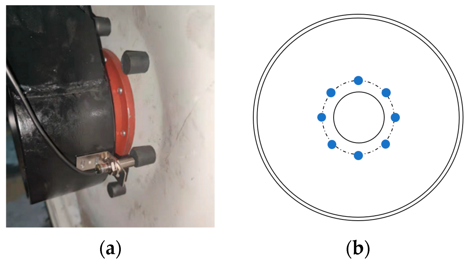
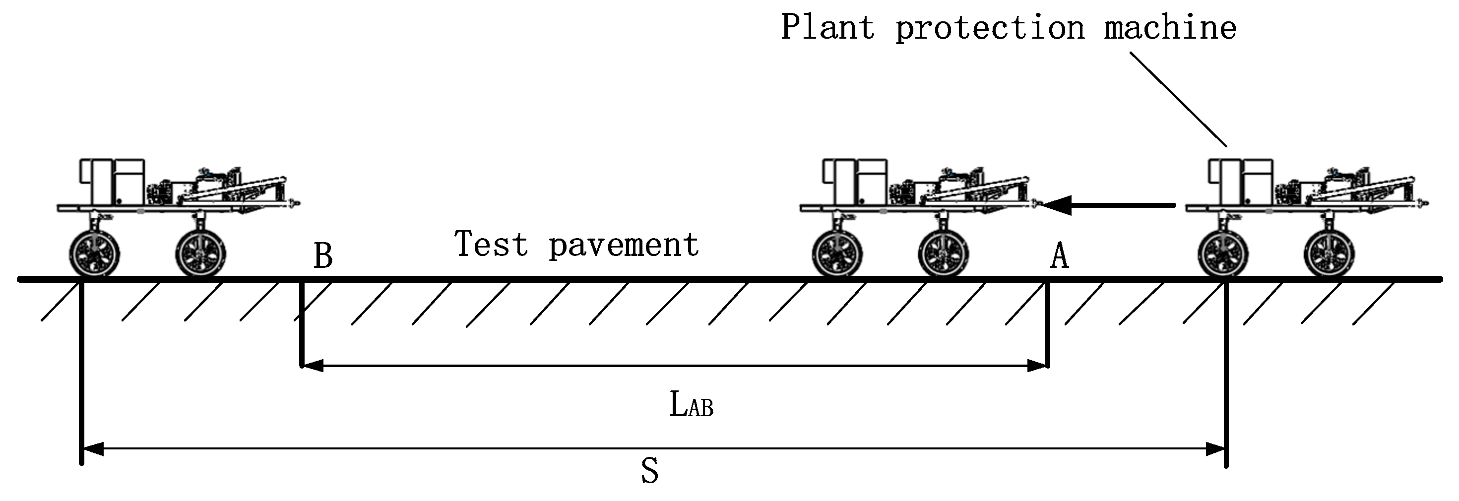
4.1. Theoretical Driving Distance Measuring Device

In order to obtain the theoretical driving straight-line distance during the driving of the hydraulic chassis, a theoretical driving distance measuring device is set up, which is composed of a proximity switch and a circular iron column. Among them, the installation method of the proximity switch is shown in Figure 12a, and the distribution of the circular iron columns is shown in Figure 12b.
Every time the proximity switch senses the end face of the circular iron column, a pulse signal is generated. The controller can collect the pulse signal and save it, and calculate the theoretical driving distance of the hydraulic chassis. The theoretical driving distance formula is:
S t = 2 π R N P .
In Formula (11), N is the number of pulses collected in the acquisition period; P is the number of pulses in one rotation of the wheel; R   is the tire radius, 0.40 m.

4.2. Test Plan and Result Analysis

In order to test the driving stability of the four-wheel drive hydraulic chassis and the anti-slip performance of the hydraulic chassis, the theoretical driving distance and the actual driving distance of the hydraulic chassis at different speeds in the field conditions were measured, and the slip rate of the hydraulic chassis of the plant protection machine was calculated.
In the process of driving on the field road, the hydraulic chassis is complex and difficult to estimate with empirical formulas. In order to obtain a more accurate slip rate, the hydraulic chassis is tested on the field for slip rate. The slip rate calculation formula is:
S r = ( v t v v t ) t = S t S S t   .
In Formula (12): St is the theoretical driving distance, the unit is m; S is the actual driving distance, the unit is m.
The experimental test plan is shown in Figure 13. The two lines. A and B, are the starting line and the ending line respectively, and the distance LAB between AB is 35 m. Before the slip rate test, the front of the car should be located in front of the starting line A, and the center point position S1 of the right front wheel should be recorded. After the tail of the hydraulic chassis crosses the end line B, the position S2 of the right front wheel should be recorded, and then the S1 and the actual driving distance S1 between S2 is finally obtained through the straight-line driving distance measuring device to obtain the theoretical driving distance St, and the slip ratio of this test is obtained by calculation.

4.2.1. The Diverter Valve Is Closed

The diverter valve is closed, and the test field is driven at a speed of 3 km/h. The theoretical driving distance is obtained by the measuring device, and the actual driving distance is measured by a tape measure. Measure five groups of test data, calculate the slip rate of each group and take the average value of the five groups of test slip rates.
The diverter valve is in a closed state, and the test field is driven at a speed of 6 km/h. The theoretical driving distance is obtained by the measuring device, and the actual driving distance is measured by a tape measure. Measure five groups of test data, calculate the slip rate of each group and take the average value of the five groups of test slip rates.

4.2.2. The Diverter Valve Is Opened

The diverter valve is open, and the test field is driven at a speed of 3 km/h. The theoretical driving distance is obtained by the measuring device, and the actual driving distance is measured by a tape measure. Measure five groups of test data, calculate the slip rate of each group and take the average value of the five groups of test slip rates.
The diverter valve is open, and the test field is driven at a speed of 6 km/h. The theoretical driving distance is obtained by the measuring device, and the actual driving distance is measured by a tape measure. Measure five groups of test data, calculate the slip rate of each group and take the average value of the five groups of test slip rates.
The slip rate test data table is shown in Table 6 and Table 7. It can be seen from the data in the table that when the hydraulic chassis travels at 3 km/h, the diverter valve is closed, the maximum slip rate is 4.69%, and the average slip rate is 3.79%; The diverter valve is opened, and the maximum slip rate is 1.69%, with an average slip rate of 1.33%. When the hydraulic chassis travels at 6 km/h, the diverter valve is closed, or the maximum slip rate is 8.64%, and the average slip rate is 6.64%; the diverter valve is opened, and the maximum slip rate is 3.04%, and the average slip rate is 2.70%. Through the test, it can be seen that the design of the four-wheel drive walking hydraulic system of the plant protection machine in this paper can effectively reduce the problem of the large slip rate of the plant protection machine in the field. Driving stability during field work is guaranteed.

5. Discussion

According to the functional requirements of the plant protection machine. A four-wheel drive hydraulic chassis is designed, including the design of four-wheel drive walking system. The walking hydraulic system is selected and calculated. AMESim software is used to model the walking hydraulic system, and the influence of four-wheel drive and two-wheel drive on the turning radius and power problems are analyzed. The advantages of this design are proved by comparing the degree of solving the slip phenomenon between the shunt valve and the synchronous motor, which proves that the machine designed in this paper has great advantages.

5.1. Comparison between Four Wheel Drive and Two Wheel Drive

Combined with the characteristics of large-scale plant protection machinery with hydraulic chassis four-wheel drive, four-wheel drive has the characteristics of four-wheel grip, uniform distribution of friction (driving force), reduction of body slip, and relative safety. It can improve the driving stability of the vehicle in the process of driving, prevent the vehicle from sliding and causing damage to surrounding objects, and at the same time, it can improve the operation efficiency of the machine in the process of operation and fully show the advantages of the machine.

5.2. The Diverter Valve Is Compared with the Synchronous Motor

The use of shunt valve can improve the driving stability of the machine during operation and reduce the slip rate of the machine. If the vehicle slips during driving, it is necessary to open the diverter valve to divert to reduce and prevent the vehicle from slipping. This machine is suitable for paddy fields and other lands with poor pavement conditions.
In order to realize the driving stability of the hydraulic chassis of the plant protection, the four-wheel drive hydraulic system is adopted, and the shunt valve is used to control the driving system of the hydraulic chassis of the plant protection machine for traveling, so as to improve the driving stability of the plant protection machine in the driving process. In the process of driving in water field and soft land, it is easy to slip and turn. At this moment, the close combination of shunt valve and four-wheel drive method can effectively reduce the occurrence of slippage.

6. Conclusions

In this paper, starting from the actual work requirements of the plant protection machine, the hydraulic chassis walking drive system of the plant protection machine is designed, and the parameters of the designed system are calculated and matched. Then, the three motion conditions of the walking hydraulic system are simulated and analyzed by AMESim software. Finally, to further verify the driving stability of the hydraulic chassis walking drive system of the designed plant protection machine, the anti-slip test is carried out in the field and the relevant conclusions are as follows:
Compared with the drive system designed in literature [18], the fluid drive method is used in literature [18] to establish the walking hydraulic system based on the analysis of the working principle of the drive system of the orchard transporter, and the walking hydraulic system is simulated by AMESim simulation software, and it is known that the uniform speed state driving can reach 0.71 m/s in the state of tractor trailer. The four-wheel drive walking hydraulic system of the plant protection machine proposed in this study—with the characteristics of fast directional change, stepless speed control and convenient regulation—uses four-wheel drive to work in the work site, and the maximum driving speed can reach 10 km/h, and can use a speed of 6 km/h to drive in the field at uniform speed. Compared with [19], a special chassis for rice agronomy was designed in [19], which can solve the problems large damage to seedlings, complex transmission, and large steering radius when the spraying machine is walking in the field, but it did not consider also the occurrence of slip and turn state when the agricultural equipment is walking in the field. Compared with the drive system designed in the literature [20], the technical solution of the fully hydraulic drive chassis drive system in the literature [20] uses a closed circuit with a single pump and four motors and uses synchronous motors for anti-skid turn control to achieve the driving stability of this agricultural equipment. The four-wheel drive driving hydraulic system proposed in this study uses a closed circuit with a single pump and four motors and uses a shunt valve for anti-slip control in order to improve the driving stability of the hydraulic chassis of the plant protection machine, which is less costly than the use of synchronous motors and has better stability for the stability of the four-wheel drive. After the test, as shown in Table 6 and Table 7, the average slip rate is 3.97 when the farm machine is running at 3 km/h and 6.17 when the farm machine is running at 6 km/h when the diverter valve is not opened, and the average slip rate is 1.33 when the farm machine is running at 3 km/h and 2.70 when the farm machine is running at 6 km/h when the diverter valve is opened. In this study, the four-wheel drive hydraulic system was simulated by AMESim software, and in Figure 9a,b, the flow and speed of the left front wheel were subjected to the minimum load in the state of the diverter valve closed, and the flow and pressure reached the extreme value, and the flow and speed of the other wheels reached the minimum value, and the slippage state appeared; in the state of the diverter valve open, the flow and speed of the four wheels were made to reach the same The flow and speed of the four wheels will be the same when the diverter valve is opened.
The hydraulic chassis of the plant protection machine designed in this paper can realize functions such as hydraulic stepless speed regulation and reversing and meet the functional requirements of the plant protection machine.
The simulation results show that the walking hydraulic system of the plant protection machine designed in this paper can be controlled by the diverter valve to make the wheels out of the slip state, so that the hydraulic chassis of the plant protection machine can restore the driving force and improve the driving performance of the plant protection machine. The simulation results verify the feasibility of the traveling hydraulic system and provide a guarantee for the subsequent test tests.
The test results show that the hydraulic chassis of the plant protection machine has been tested for stability. Under the condition that the diverter valve is closed, drive in a straight line at 3 km/h and 6 km/h respectively, obtain the theoretical driving distance through the theoretical straight line measuring device and calculate the average slip rate under the two speed conditions. Under the condition that the diverter valve is open, respectively 3 km/h, 6 km/h for straight-line driving, obtain the theoretical driving distance through the theoretical straight-line measuring device and calculate the average slip rate under the two speed conditions. The test results show that when the diverter valve is open, the slip rate during driving under two speed conditions is lower than the slip rate when the diverter valve is not opened. It is proved that the hydraulic chassis designed in this paper has good driving stability.

Author Contributions

Conceptualization, C.Z. (Chengliang Zhang) and L.L.; writing-review and editing, C.L.; Validation, C.Z. (Chunzhao Zhao), G.G. and X.C. All authors have read and agreed to the published version of the manuscript.

Funding

This work was supported by the Key R&D Program of Shandong Province (2019JZZY020616, 2020CXGC011001, 2020CXGC011003 and 2019JZZY010453), and Shandong Provincial Major Agricultural Applied Technological Innovation Projects (SD2019NJ012).

Conflicts of Interest

The authors declare no conflict of interest.

References

  1. Zhang, S. Application and advantage analysis of hydraulic system in agricultural mechanization. Anhui Agric. Sci. 2014, 20, 6872–6873. [Google Scholar]
  2. Hu, K.; Zhang, W.; Qi, B.; Minutes.; Li, K.; Yan, W. Application and development of hydraulic chassis in the field of agricultural machinery. Jiangsu Agric. Sci. 2019, 47, 259–263. [Google Scholar]
  3. Zhang, X. Review of the development of hydraulic technology for mobile machinery at home and abroad. Fluid Transm. Control 2017, 3, 1–11. [Google Scholar]
  4. Zhang, L. The application of hydrostatic drive system in the field of agricultural machinery. Hydraul. Pneum. Seal. 2014, 34, 78–80. [Google Scholar]
  5. Kumar, S.; Tewari, V.; Bharti, C.K.; Ranjan, A. Modeling, simulation and experimental validation of flow rate of electro-hydraulic hitch control valve of agricultural tractor. Flow Meas. Instrum. 2021, 82, 102070. [Google Scholar] [CrossRef]
  6. Hong, Y.; Zhang, X. Design and analysis of hydraulic chassis with obstacle avoidance function. IOP Conf. Ser. Mater. Sci. Eng. 2017, 224, 012005. [Google Scholar] [CrossRef] [Green Version]
  7. Axin, M.; Eriksso, B.; Krus, P. A flexible working hydraulic system for mobile machines. Int. J. Fluid Power 2016, 17, 79–89. [Google Scholar] [CrossRef]
  8. Li, R.; Cheng, Y.; Xu, J.; Li, Y.; Ding, X.; Zhao, S. Research on on-line monitoring system of hydraulic actuator of combine harvester. Processes 2022, 10, 35. [Google Scholar] [CrossRef]
  9. Shyrokau, B.D.; Winter, J.; Stroosma, O.; Dijksterhuis, C.; Loof, J.; van Paassen, R.; Happee, R. The effect of steering-system linearity, simu-lator motion, and truck driving experience on steering of an articulated tractor-semitrailer combination. Appl. Ergon. 2018, 71, 17–28. [Google Scholar] [CrossRef]
  10. Nayl, T.; Nikolakopoulos, G.; Gustafsson, T.; Kominiak, D.; Nyberg, R. Design and experimental evaluation of a novel sliding mode controller for an articulated vehicle. Robot. Auton. Syst.-Tems 2018, 103, 213–221. [Google Scholar] [CrossRef]
  11. Gonzalez, D.O.; Martin-Gorriz, B.; Berrocal, I.I.; Hernandez, B.M.; Garcia, F.C.; Sanchez, P.M. Development of an automatically deployable roll over protective structure for agricultural tractors based on hydraulic power: Prototype and first tests. Comput. Electron. Agric. 2016, 124, 46–54. [Google Scholar] [CrossRef]
  12. Wang, Y. Development of hydraulic drive technology for mobile machinery. Hydraul. Pneum. Seal. 2000, 3, 1–6. [Google Scholar]
  13. Zhao, J.; Xu, L.; Zhang, J.; Zhao, X. Research and application status of hydrostatic drive technology for off-road vehicles. Tract. Agric. Transp. Veh. 2018, 45, 8–13. [Google Scholar]
  14. Sun, Y.; Zhang, H.; Yang, J. The structure principle and dynamic characteristics of mechanical-electric-hydraulic dynamic coupling drive system and its application in electric vehicle. Electronics 2022, 11, 1601. [Google Scholar] [CrossRef]
  15. Minav, T.A.; Laurila, L.I.; Pyrh, J.J. Analysis of electro-hydraulic lifting system’s energy efficiency with direct electric drive pump control. Autom. Constr. 2013, 30, 144–150. [Google Scholar] [CrossRef]
  16. Jiang, Z.; Xia, C. Research on the characteristics of tractor hydrostatic transmission system. Agric. Mech. Res. 2021, 43, 249–254. [Google Scholar]
  17. He, L.; Chen, Z.; Zhou, H. Design of hydrostatic chassis of crawler harvester. Mod. Agric. Equip. 2017, 3, 26–28+33. [Google Scholar]
  18. Li, J.; Li, S.; Zhang, Y.; Wu, H.; Liu, M.; Gao, Z. Design of hydraulic drive system of mountain orchard conveyor. J. Anhui Agric. Univ. 2021, 48, 143–149. [Google Scholar]
  19. Nie, Y.; Wu, Y.; Li, C.; Xu, W. Design and test of hydraulic chassis of high ground clearance sprayer. Nanfang Agric. Mach. 2020, 51, 10–12. [Google Scholar]
  20. Hu, K.; Zhang, W.; Liu, H.; Li, K. Design and simulation of hydraulic drive system for hilly and mountain tractor. Mach. Tool Hydraul. 2021, 49, 93–97. [Google Scholar]
  21. Mononen, T.; Mattila, J. Flow-bounded velocity controller for hydraulic bulldozers. Energies 2022, 15, 4027. [Google Scholar] [CrossRef]
  22. Mo, S. Cross-border mergers and acquisitions in the agricultural machinery industry—The fifth in a series of big talk about agricultural machinery. Agric. Mach. 2013, 25, 22–23. [Google Scholar]
  23. Liu, Z. Design and Simulation Study of Hydraulic System of High Ground Clearance Plant Protection Machine; Hunan Agricultural University: Changsha, China, 2020. [Google Scholar]
  24. Zheng, W.; Zhao, T.; Dang, B.; Li, S. Research on the control of hydraulic driving system of cleaning vehicle based on fuzzy PID. Electromech. Technol. 2018, 4, 84–87+113. [Google Scholar]
  25. Wu, Q. New trends in the development of foreign combine harvester technology. Contemp. Agric. Mach. 2014, 10, 50–51. [Google Scholar]
  26. Liu, X.; Yang, M.; Chen, W. Design of four-wheel independent drive hydraulic power system for logging machinery. For. Mach. Woodwork. Equip. 2019, 47, 14–16. [Google Scholar]
  27. Hu, K.; Zhang, W.; Yu, S.; Qi, B. Minutes. Design and research of full hydraulic chassis drive system for high-speed rice transplanter. Mod. Manuf. Eng. 2018, 10, 141–145. [Google Scholar]
  28. Fan, X.; Wei, X. Design of automatic driving system for four-wheel steering hydraulic chassis. Agric. Mech. Res. 2017, 39, 253–258. [Google Scholar]
  29. Wang, G.; Song, Y.; Wang, J.; Chen, W.; Cao, Y.; Wang, J. Study on the Shifting Quality of the CVT Tractor under Hydraulic System Failure. Appl. Sci. 2020, 10, 681. [Google Scholar] [CrossRef] [Green Version]
  30. Zhou, C.; Zhang, Q.; Qing, R. A dual-pump combined frequency conversion hydraulic speed control system. Mach. Tool Hydraul. 2022, 50, 100–103. [Google Scholar]
  31. Zhao, L.; Deng, N.; Luo, N.; Liu, X. Sliding mode control of four-wheel steering. J. South China Univ. Technol. 2015, 43, 69–74+81. [Google Scholar]
  32. Xia, C.; Luo, G. Design and analysis of full hydraulic four-wheel steering system of sprayer. J. Chongqing Univ. Technol. 2016, 30, 65–70. [Google Scholar]
  33. Yang, M. Study on the Digital hydraulic driving system of the belt conveyor. Machines 2022, 10, 417. [Google Scholar] [CrossRef]
  34. Zhu, Z.; Yang, Y.; Wang, D.; Cai, Y.; Lai, L. Energy saving performance of agricultural tractor equipped with mechanic-electronic-hydraulic powertrain system. Agriculture 2022, 12, 436. [Google Scholar] [CrossRef]
Figure 1. Structure diagram of the hydraulic chassis of the plant protection machine. 1—Spray rod, 2—Lifting cylinder, 3—Engine, 4, 5—Hydraulic pump, 6—Frequency conversion motor, 7—Steering cylinder, 8—Control valve group, 9—Hydraulic tank, 10—Oil radiator, 11—Gear pump, 12—Rear suspension, 13—Wheel drive motor, 14—battery, 15—Medicine box.
Agriculture 12 01118 g001
Figure 2. The principle diagram of the walking hydraulic system of the plant protection machine. 1—Variable pump, 2—Flushing valve, 3—Diverter collecting valve, 4—Hydraulic motor for left rear wheel, 5—Right rear wheel hydraulic motor, 6—Left front wheel hydraulic motor, 7—Right front wheel hydraulic motor.
Agriculture 12 01118 g002
Figure 3. AMESim simulation modeling of diverter valve.
Agriculture 12 01118 g003
Figure 4. The trend curve of the diverter valve sample. (a) power outage; (b) power ups.
Agriculture 12 01118 g004
Figure 5. Modeling trend curve of diverter valve. (a) power outage; (b) power ups.
Agriculture 12 01118 g005
Figure 6. AMESim simulation model of the walking hydraulic system. 1—engine, 2—main pump, 3, 4—high pressure relief valve, 5—low pressure relief valve, 6—oil pump, 7—flushing valve, 8—split valve input signal, 9—Left front wheel load torque, 10—Left front wheel hydraulic motor, 11—Right front wheel hydraulic motor, 12—Right front wheel load torque, 13—left rear wheel load torque, 14—left rear wheel hydraulic motor, 15—right rear wheel hydraulic motor, 16—right rear wheel load torque, 17—diverter valve.
Agriculture 12 01118 g006
Figure 7. The motor speed and flow curve of working condition 1. (a) Motor speed; (b) Flow.
Agriculture 12 01118 g007
Figure 8. The motor speed and flow curve of working condition 2. (a) Motor speed; (b) Flow.
Agriculture 12 01118 g008
Figure 9. Diverter valve signal input in working condition 3.
Agriculture 12 01118 g009
Figure 10. The motor speed and flow curve of working condition 3. (a) Motor speed; (b) Flow.
Agriculture 12 01118 g010
Figure 11. Anti-slip test.
Agriculture 12 01118 g011
Figure 12. Theoretical travel distance measuring device. (a) Installation method; (b) Circular iron column arrangement.
Agriculture 12 01118 g012
Figure 13. Experimental test scheme.
Agriculture 12 01118 g013
Table 1. Main design parameters of the plant protection machine.
The Main ParametersNumerical Value
Overall size (mm)3050 × 1350 × 2000
Machine working weight whole machine (kg)2000
Minimum turning radius (m)4.5
Drive wheel radius (m)0.4
Field work speed (km/h)3~6
Travel maximum speed (km/h)10
Table 2. Rolling resistance coefficient f and adhesion coefficient φ.
Pavement TypeFeatureRolling Resistance
Coefficient
Adhesion
Coefficient
Concrete pavementHard road0.010~0.0200.8~0.9
Compact dirt roadFirm road0.025~0.0150.5~0.65
Dry fieldsHard ground0.150~0.2000.6~0.7
Cultivate the landSoft land0.100~0.2500.5~0.7
Table 3. Main parameters of hydraulic motor.
CharacteristicParameter
Equivalent displacement (mL/r)417.3
Maximum working pressure (MPa)21
Maximum flow (L/min)20.7
Maximum output speed (r/min)49.6
Maximum output torque (N·m)1396
Table 4. Main parameters of hydraulic pump.
CharacteristicParameter
Displacement (mL/r)20
Maximum pressure (MPa)34.5
Rated speed (r/min)4000
Maximum speed (r/min)4500
Weight (kg)12
Table 5. Main simulation parameters of hydraulic system.
The Main ParametersNumerical Value
Engine rated speed (r/min)3000
Variable displacement piston pump (mL/r)20
Charge pump displacement (mL/r)4.3
Wheel side hydraulic motor maximum load torque (N·m)980
Wheel side hydraulic motor displacement (mL/r)417.3
Shunt valve control current (mA)40
High pressure relief valve pressure (bar)300
Charge relief valve pressure (bar)7
Table 6. Test data table of slip rate when the diverter valve is not opened.
SpeedGroupActual Driving
Distance (m)
Theoretical Driving
Distance (m)
Slip Rate (%)Average Slip (%)
3 km/h139.8541.373.683.79
239.5441.153.92
339.6441.594.69
439.3340.933.92
539.5940.712.76
6 km/h139.4642.256.606.17
238.9242.027.39
339.2441.595.65
439.8842.476.09
539.6741.815.11
Table 7. Diverter valve opening slip rate test data table.
SpeedGroupActual Driving
Distance (m)
Theoretical Driving
Distance (m)
Slip Rate (%)Average Slip (%)
3 km/h139.0139.400.091.33
238.9539.621.69
339.2339.831.53
439.8440.281.08
539.5140.051.37
6 km/h139.2640.272.522.70
238.8440.053.04
339.4140.502.68
438.6839.842.91
539.7740.712.32
Publisher’s Note: MDPI stays neutral with regard to jurisdictional claims in published maps and institutional affiliations.

