
Development of a Personal Mobility System with Autonomous Driving for Agricultural Work by the Physically Challenged and the Vulnerable

Abstract
:1. Introduction
2. Design and Analysis
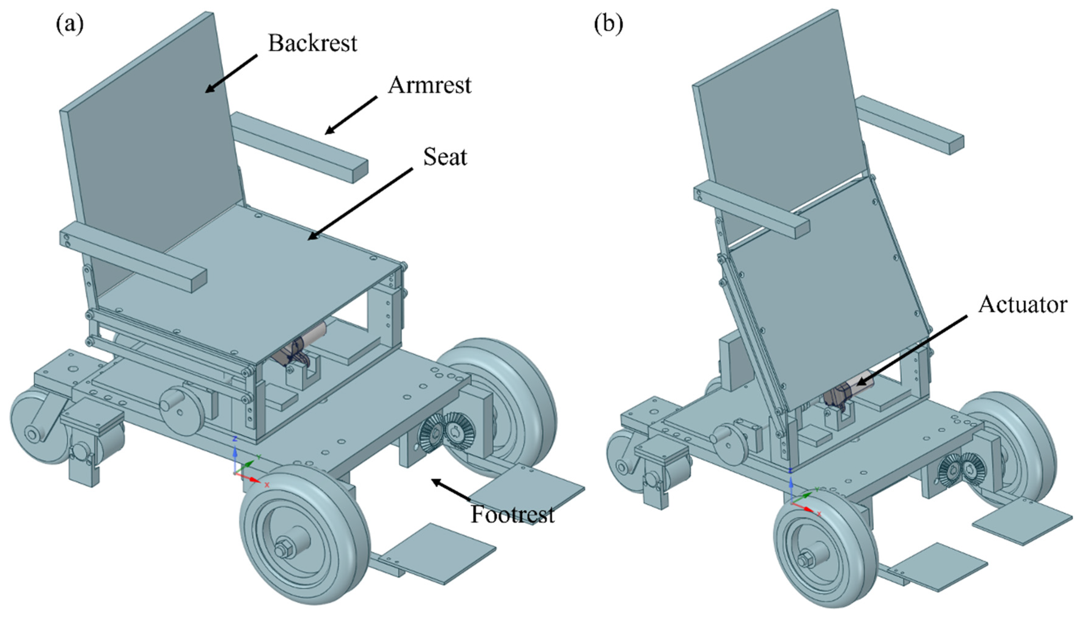
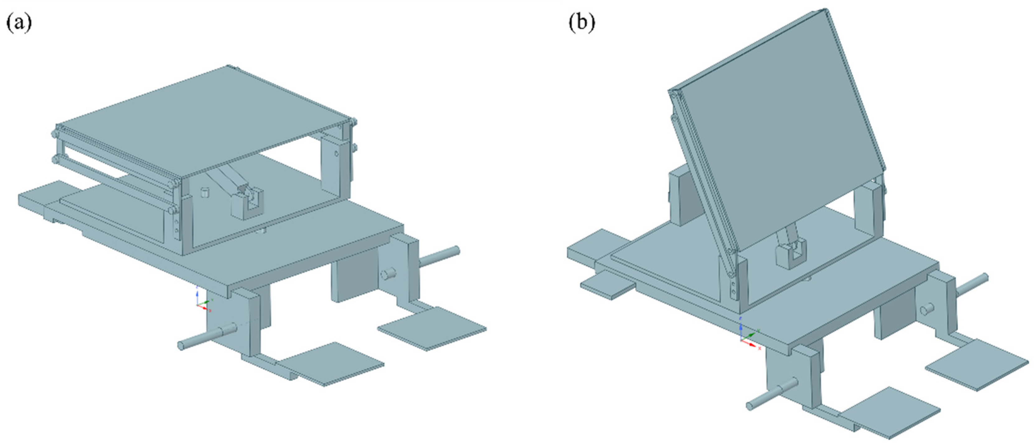
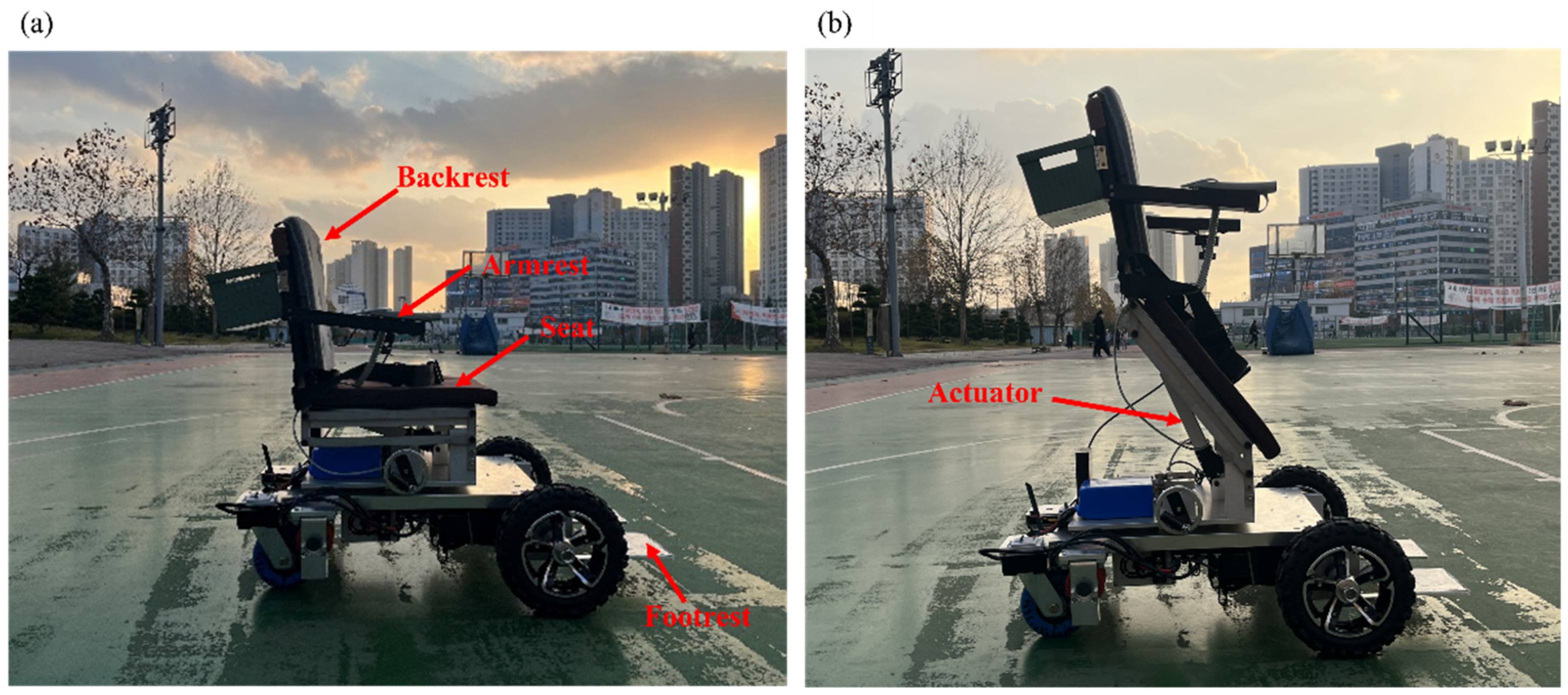
2.1. Design
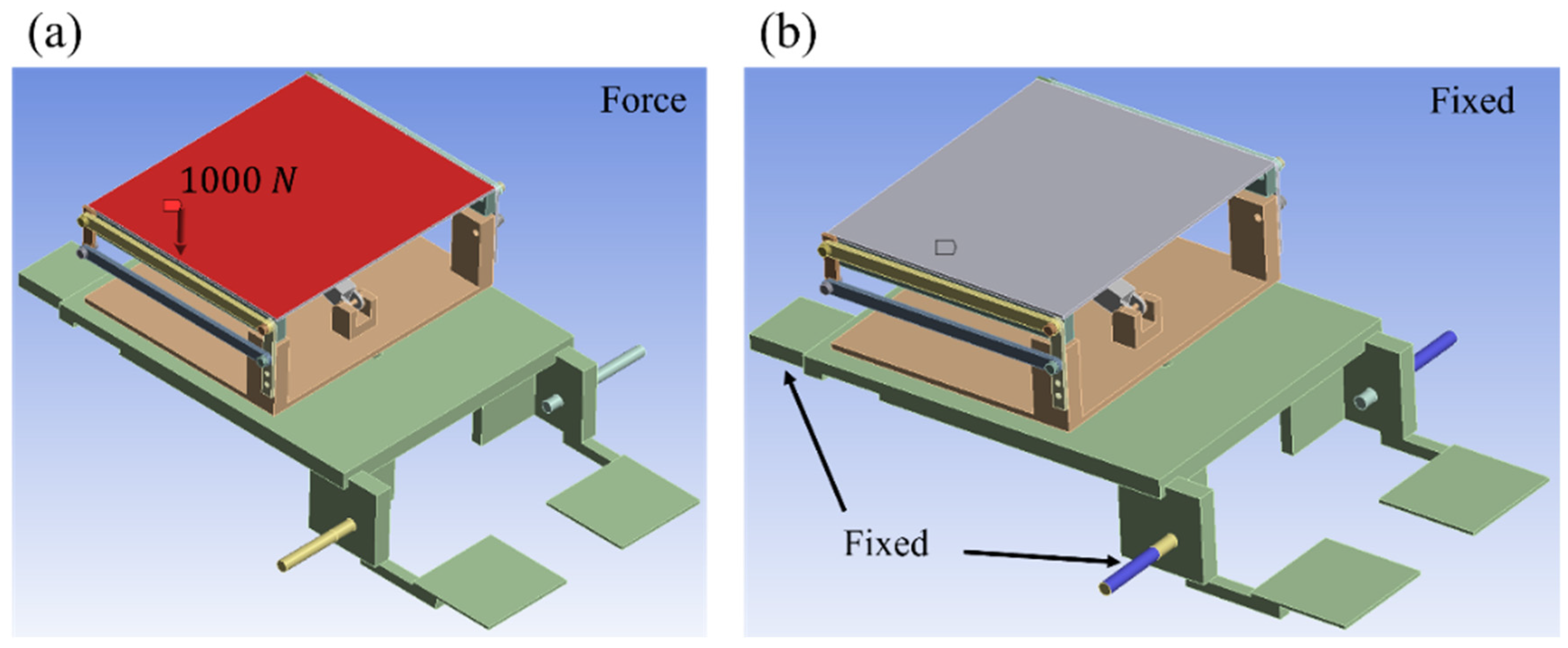
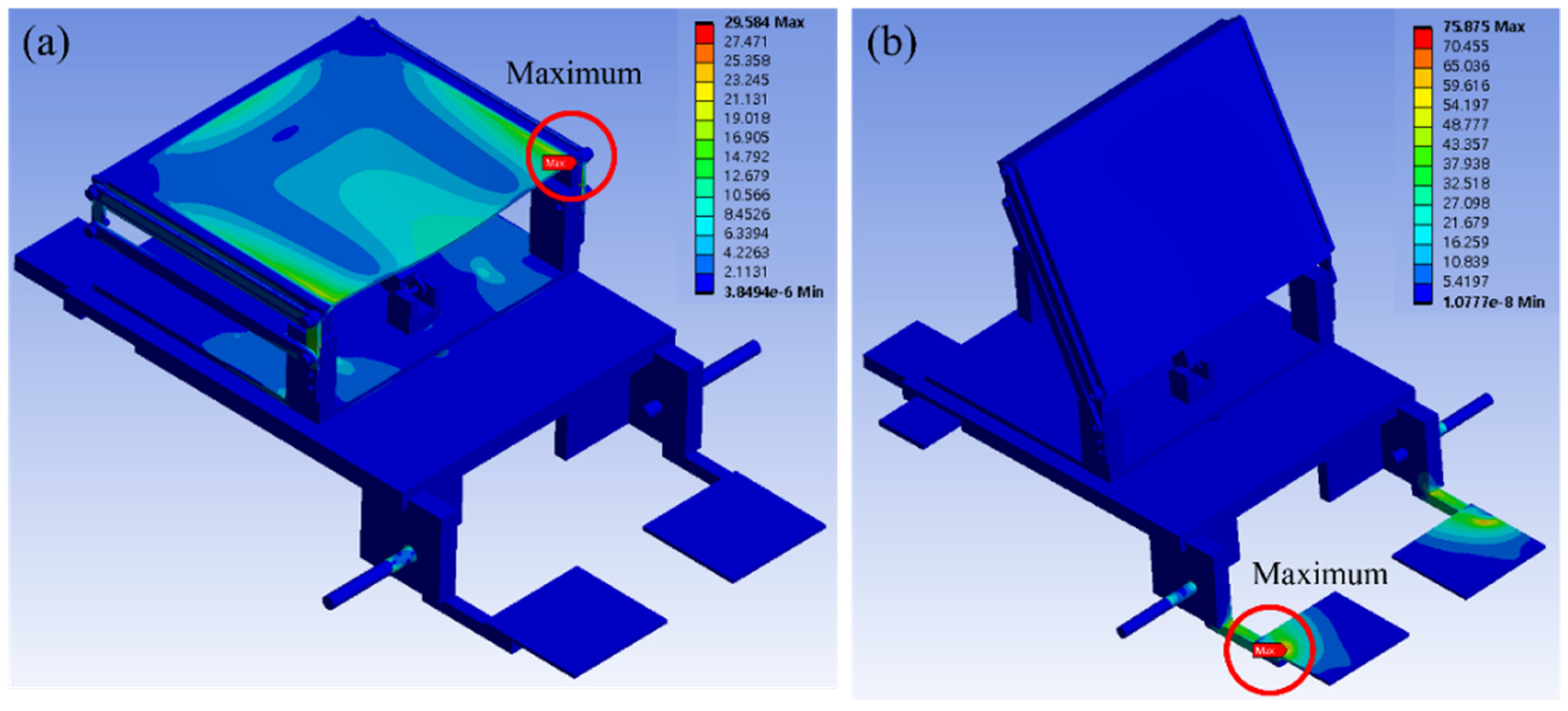
2.2. Analysis
3. System Overview
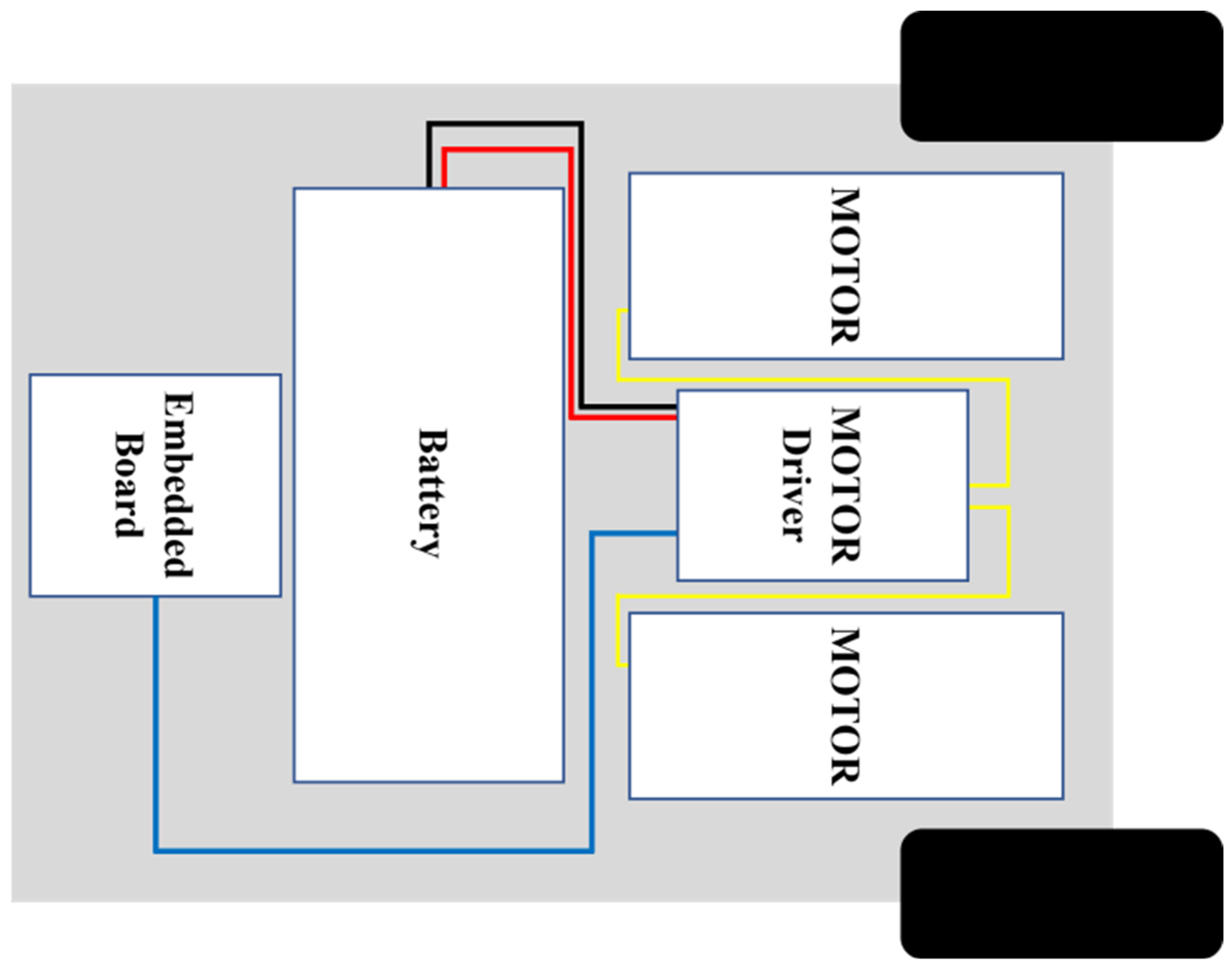
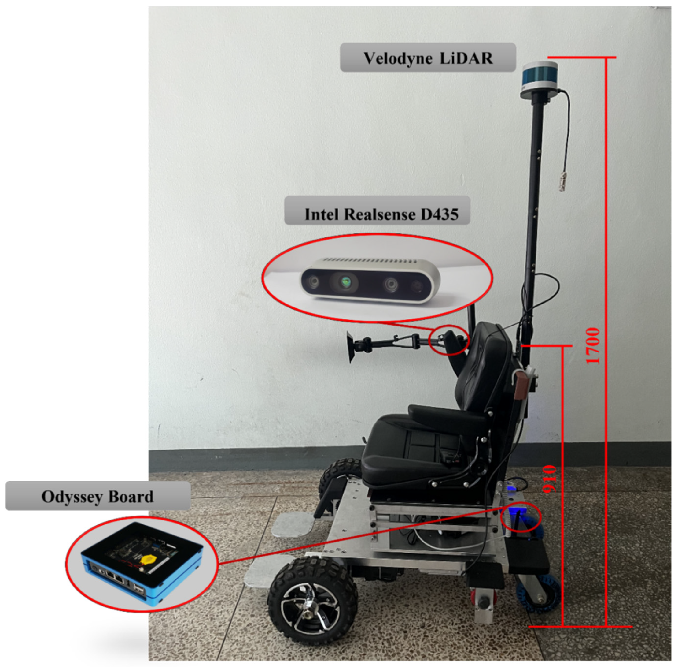
3.1. Hardware
3.2. Software
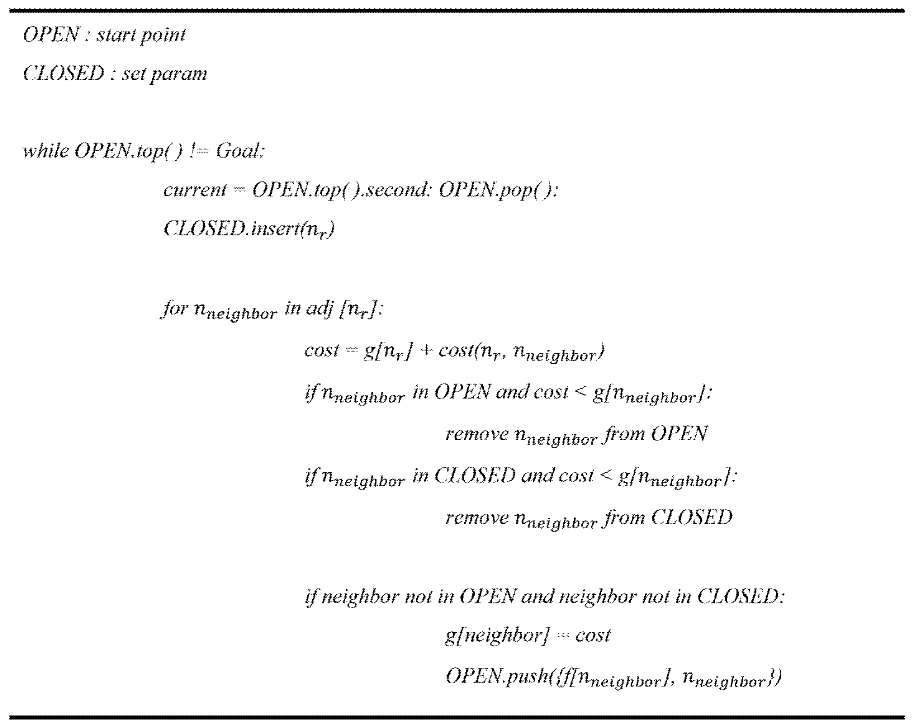
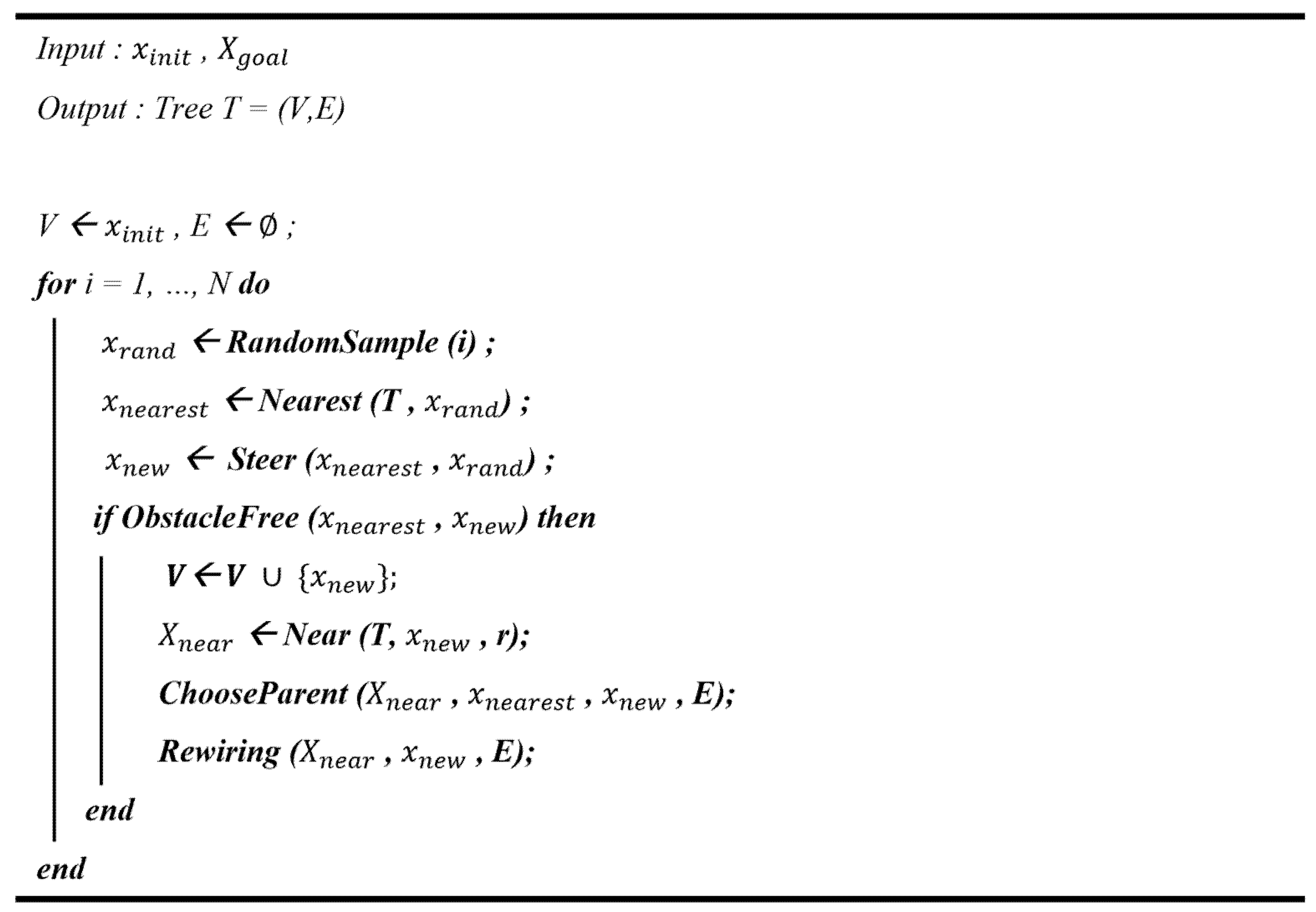
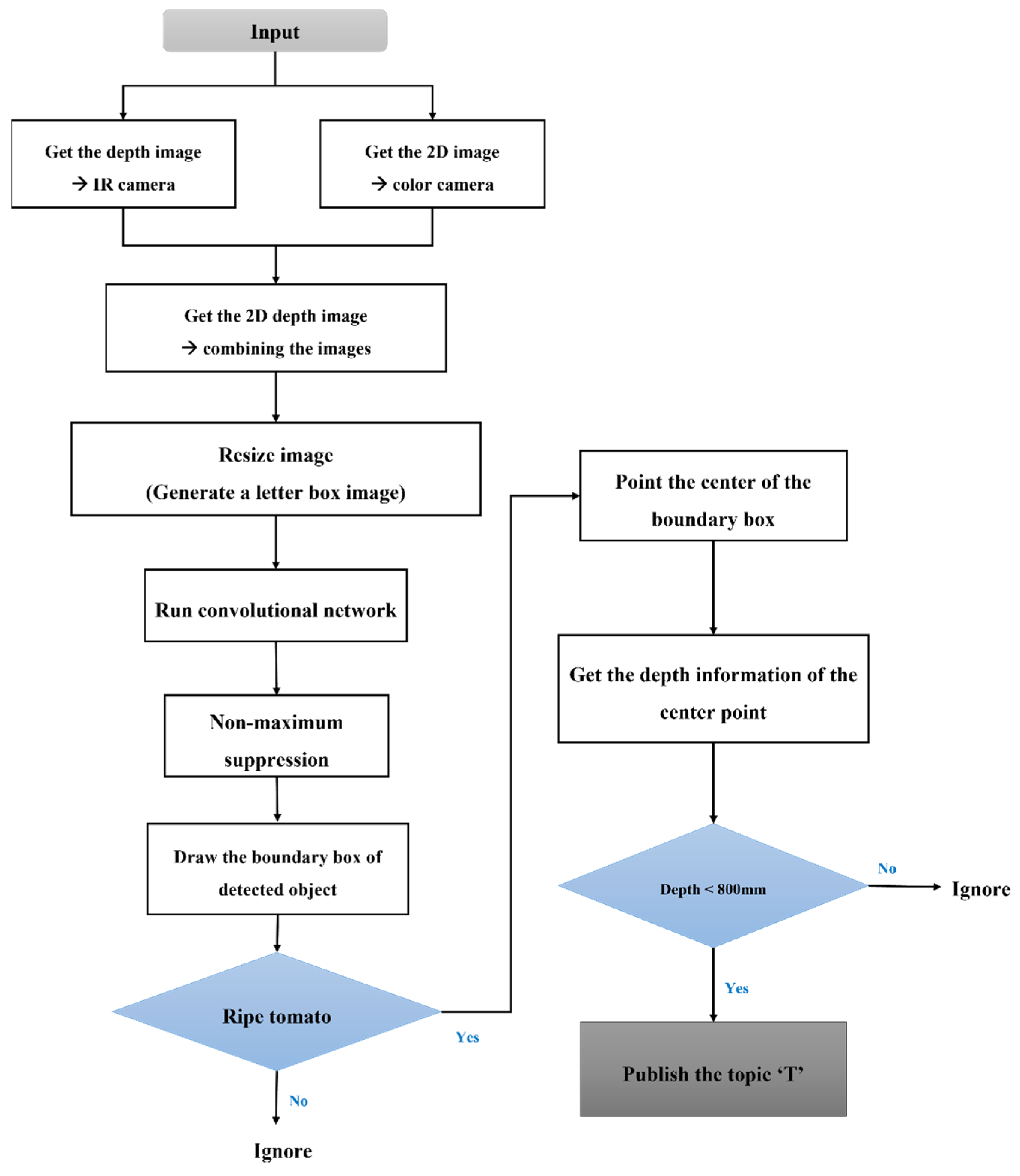
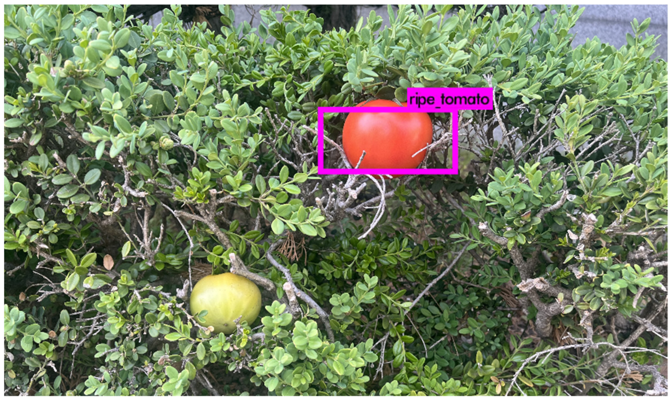
3.3. Deep-Learning Algorithm for the Autonomous System
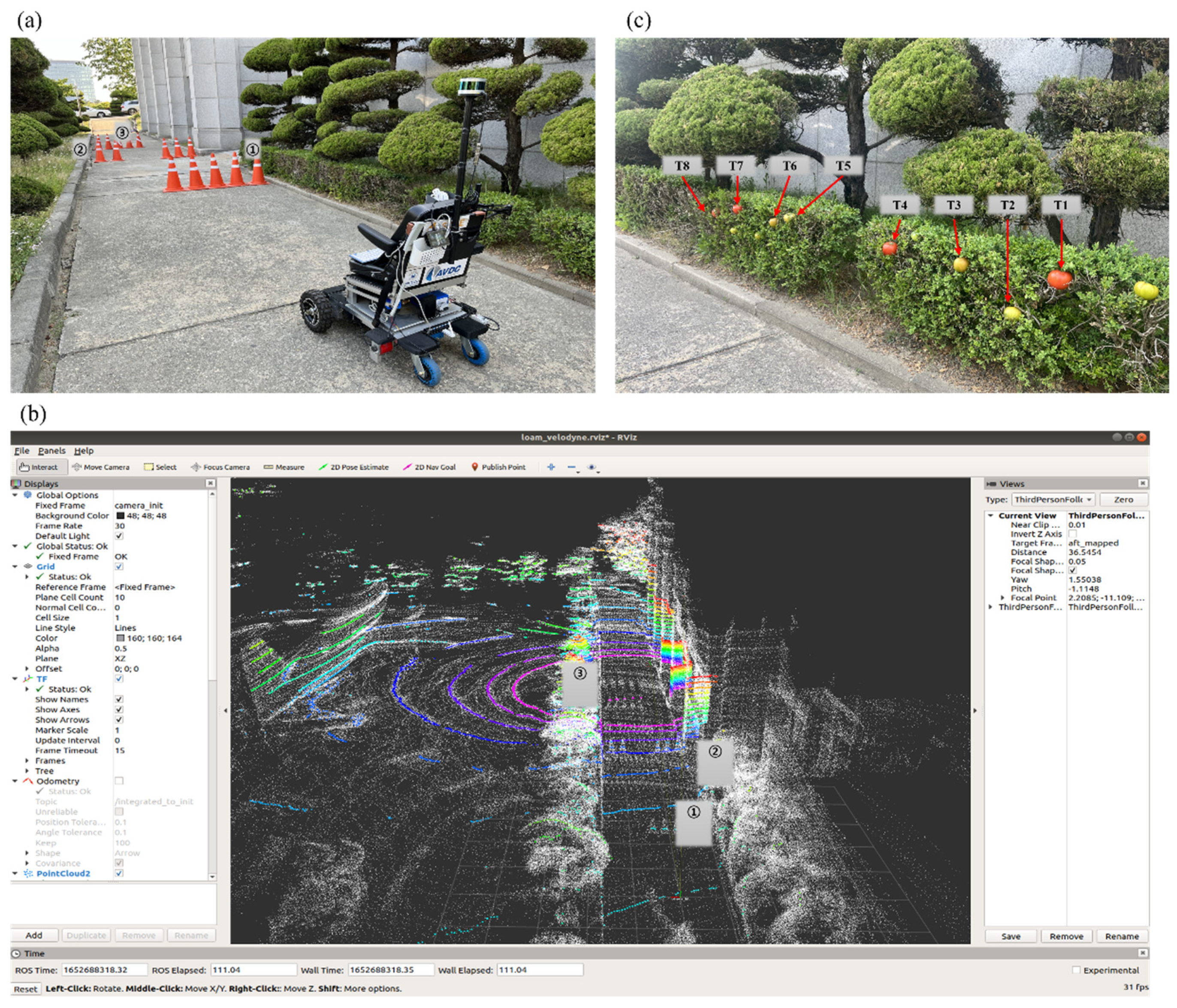
3.4. Experiment

| Position ① | Position ② | Position ③ | |
|---|---|---|---|
| A* | 1.368 (s) | 0.478 (s) | 1.962 (s) |
| RRT | 1.498 (s) | 0.871 (s) | 2.689 (s) |
4. Conclusions
Author Contributions
Funding
Institutional Review Board Statement
Informed Consent Statement
Data Availability Statement
Acknowledgments
Conflicts of Interest
References
- Scobie, J. Global AgeWatch Index 2015 Insight Report; HelpAge International: London, UK, 2015; pp. 5–6. [Google Scholar]
- Kim, A.J.; Kweon, O.S. The Effect of User Interface of Power Wheelchair for People with Spinal Cord Injuries on Usability. Des. Work. 2018, 1, 12–22. [Google Scholar]
- Song, C.Y.; Yoon, H.J.; Lee, C. Development of Standing and Gait Assistive Wheelchair. J. Manuf. Eng. Technol. 2013, 22, 587–592. [Google Scholar] [CrossRef]
- Han, K.H.; Lee, C.-H. A Study on the Development of Personal Mobility for the Vulnerable Group. J. Drive Control. 2021, 18, 35–42. [Google Scholar]
- Jung, M.W.; Lee, S.H. Object Perception Algorithm based on LiDAR for Autonomous Vehicle. Korean Soc. Electron. Eng. Conf. 2017, 37, 639–642. [Google Scholar]
- Choi, J.H.; Kim, M.H.; Choi, B.J. Development of a platform based on image signal processing for autonomous driving of electric wheelchairs. J. Korean Inst. Intell. Syst. 2018, 28, 231–236. [Google Scholar]
- Prassler, E.; Scholz, J.; Fiorini, P. A robotics wheelchair for crowded public environments. IEEE Robot. Autom. Mag. 2001, 8, 38–45. [Google Scholar] [CrossRef]
- Lu, K.; Zhang, Y.; Li, H. Research Status and Development Trend of Path Planning Algorithm for Unmanned Vehicles. IOP Conf. Ser. J. Phys. Conf. Ser. 2019, 1213, 032006. [Google Scholar] [CrossRef]
- Lee, Y.M.; Seo, Y.D. Vision-Based SLAM in Augmented/Mixed Reality. J. Korea Multimed. Soc. 2009, 13, 12–20. [Google Scholar]
- Zhang, J.; Singh, S. LOAM: Lidar Odometry and Mapping in Real-time (or Low-drift and Real-time Lidar Odometry and Mapping). Auton. Robot. 2017, 41, 401–416. [Google Scholar] [CrossRef]
- Lavalle, S.M. Rapidly-exploring random trees: A new tool for path planning. Comput. Sci. Dept. Oct 1998, 98-11. [Google Scholar]
- Tak, H.T.; Park, C.G.; Lee, S.C. Improvement of RRT*-Smart Algorithm for Optimal Path Planning and Application of the Algorithm in 2 & 3-Dimension Environment. J. Korean Soc. Aviat. Aeronaut. 2019, 27, 1–8. [Google Scholar]
- Mikolov, T.; Kombrink, S.; Burget, L.; Cernocky, J.; Khudanpur, S. Extensions of Recurrent Neural Network Language Model. In Proceedings of the 2011 IEEE International Conference on Acoustics, Speech and Signal Processing (ICASSP), Prague, Czech Republic, 22–27 May 2011; pp. 5528–5531. [Google Scholar]
- Redmon, J.; Divvala, S.; Girshick, R.; Farhadi, A. You Only Look Once: Unified, Real-Time Object Detection. In Proceedings of the IEEE Conference on Computer Vision and Pattern Recognition (CVPR), Las Vegas, NV, USA, 27–30 June 2016; pp. 779–788. [Google Scholar]
- Bochkovskiy, A.; Wang, C.-Y.; Mark Liao, H.-Y. Yolov4: Optimal speed and accuracy of object detection. arXiv 2020, arXiv:2004.10934. [Google Scholar]
- Girshick, R.; Donahue, J.; Darrell, T.; Malik, J. Rich Feature Hierarchies for Accurate Object Detection and Semantic Segmentation. In Proceedings of the IEEE Conference on Computer Vision, and Pattern Recognition (CVPR), Columbus, OH, USA, 23–28 June 2014; pp. 580–587. [Google Scholar]
- Bea, S.Y. Research Trends on Related to Artificial Intelligence for the Visually Impaired: Focused on Domestic and Foreign Research in 1993-2020. J. Korea Contents Assoc. 2020, 20, 688–701. [Google Scholar]
- Redmon, J.; Farhadi, A. YOLO9000: Better, Faster, Stronger. In Proceedings of the IEEE Conference on Computer Vision and Pattern Recognition (CVPR), Honolulu, HI, USA, 21–26 July 2017; pp. 7263–7271. [Google Scholar]
- Girshick, R. Fast r-cnn. In Proceedings of the IEEE International Conference on Computer Vision (ICCV), Santiago, Chile, 7–13 December 2015; pp. 1440–1448. [Google Scholar]
- Ren, S.; He, K.; Girshick, R.; Sun, J. Faster r-cnn: Towards real-time object detection with region proposal networks. arXiv 2015, arXiv:1506.01497. [Google Scholar] [CrossRef] [PubMed] [Green Version]
- Lee, Y.H.; Kim, Y. Comparison of CNN and YOLO for Object Detection. J. Semicond. Disp. Technol. 2020, 19, 85–92. [Google Scholar]
- Quigley, M.; Conley, K.; Faust, J.; Foote, T.; Leibs, J.; Bergr, E.; Wheeler, R.; Ng, A. ROS: An open-source Robot Operating System. ICRA Workshop Open-Source Softw. 2009, 3, 5. [Google Scholar]


| Parameter | Value |
|---|---|
| Weight (Sum of personal mobility system and maximum user weight) | 150 |
| Diameter of the driving wheel | 28.21 |
| 94.03 | |
| Acceleration time | 1.5 |
| Aluminum 5052 | MC Nylon | |
|---|---|---|
| Density | ||
| Young’s modulus | ||
| Poisson’s ratio | 0.33 | 0.4 |
| Yield strength |
| Seating Mode | Standing Mode | |
|---|---|---|
| Deformation | ||
| Stress | ||
| Safety factor | 6.52 | 2.54 |
| Recognition (O) | T1 | T2 | T3 | T4 | T5 | T6 | T7 | T8 |
|---|---|---|---|---|---|---|---|---|
| TEST 1 | O | - | - | O | - | - | O | O |
| TEST 2 | O | - | - | O | - | - | - | O |
| TEST 3 | O | - | - | O | - | - | - | O |
| TEST 4 | O | - | - | O | - | - | - | O |
| TEST 5 | O | - | - | O | - | - | O | O |
Publisher’s Note: MDPI stays neutral with regard to jurisdictional claims in published maps and institutional affiliations. |
© 2022 by the authors. Licensee MDPI, Basel, Switzerland. This article is an open access article distributed under the terms and conditions of the Creative Commons Attribution (CC BY) license (https://creativecommons.org/licenses/by/4.0/).
Share and Cite
Ko, E.; Han, K.; Lee, C.-H. Development of a Personal Mobility System with Autonomous Driving for Agricultural Work by the Physically Challenged and the Vulnerable. Agriculture 2022, 12, 1054. https://doi.org/10.3390/agriculture12071054
Ko E, Han K, Lee C-H. Development of a Personal Mobility System with Autonomous Driving for Agricultural Work by the Physically Challenged and the Vulnerable. Agriculture. 2022; 12(7):1054. https://doi.org/10.3390/agriculture12071054
Chicago/Turabian StyleKo, EunByul, KwangHo Han, and Chul-Hee Lee. 2022. "Development of a Personal Mobility System with Autonomous Driving for Agricultural Work by the Physically Challenged and the Vulnerable" Agriculture 12, no. 7: 1054. https://doi.org/10.3390/agriculture12071054