Article

Design and Experiment of an Integrated Automatic Transplanting Mechanism for Picking and Planting Pepper Hole Tray Seedlings

1
Nanjing Institute of Agricultural Mechanization, Ministry of Agriculture and Rural Affairs, Nanjing 210014, China
2
Graduate School of Chinese Academy of Agricultural Sciences, Beijing 100083, China
*
Authors to whom correspondence should be addressed.
Agriculture 2022, 12(4), 557; https://doi.org/10.3390/agriculture12040557
Submission received: 17 March 2022 / Revised: 8 April 2022 / Accepted: 11 April 2022 / Published: 13 April 2022

Abstract

:
The operation of the semi-automatic pepper pot seedling transplanter has the problem of a low frequency of manual operation. We designed a new automatic transplanting mechanism based on a clamping stem. Through the movement law of a double-crank connecting rod mechanism, the static trajectory of beak shape and the dynamic trajectory of N shape were designed to meet the requirements of backward transplanting. The kinematics equation of the seedling picking mechanism was established and the mechanism parameter optimization program was developed based on MATLAB. The effect of the mechanism parameter changes on the seedling movement trajectory was analyzed. A group of parameter combinations that met the requirements of seedling picking and planting were optimized. After optimization, the trajectory height was 220.8 mm, the picking angle was 21.03° and the planting angle was 64.15°. The plant spacing was 260 mm, which meets the agronomic requirements of pepper transplanting. Through the combination of theoretical analysis and prototype tests, the test results showed that the theoretical trajectory was basically consistent with the actual trajectory, verifying the feasibility of the mechanism design. In this study, pepper pot seedlings in the suitable planting period of 60 days were selected and planted at the rotation speed of 60, 70 and 80 r/min, respectively. The success rate of seedling selection was more than 91.1%, the success rate of planting was more than 78.5%, the qualified rate of erect degree was 94.9%, and the coefficient of variation of plant spacing was stable below 14.1%. The results show that the integrated automatic transplanting mechanism for pepper pot seedlings was effective.

1. Introduction

China is the world’s largest producer of pepper, with 40% of the world’s total pepper planting area being located in the country. As of April 2020, 28 provinces in China have planted pepper, covering an area of more than 2 million hectares, accounting for 12% of the total vegetable planting area [1]. At present, about 60% of the vegetable crop is produced by seedling transplantation [2]. Transplanting has many advantages compared with traditional cultivating. For example, transplanting only needs to maintain one point and one seedling, and therefore reduces soil-borne disease. Transplanting technology can advance crop growth by about 15 days, thereby effectively avoiding severe weather such as frost, hail and low temperatures [3]. The pepper transplanting machines popularized in China are mainly semi-automatic transplanting machines. The automatic planting process can be completed, but the process of picking seedlings depends on labor. The transplanting speed is limited by the speed of the artificial seedling picking [4]. Therefore, we need to develop a pot seedling automatic transplanter to meet the requirements of pepper agronomic production in China. The important matter is to solve the problems of injured seedlings and leaking seedlings in the process of transplanting.
The key point of this research is the design and parameter optimization of the seedling picking mechanism of the automatic transplanting machine [5]. Foreign and domestic scholars have conducted in-depth research on seedling picking mechanisms. These mechanisms can be divided into matrix type [6,7], clamping bowl type [8,9,10], top-out type [11,12,13], pneumatic type [14,15], etc. Han et al. [16] proposed a top-out seedling picking mechanism for the top clamping combination. It used bilateral parallel guide rails to limit the top-out action of the top seedling rod. They optimized the parameters of the top seedling mechanism using MATLAB to ensure its accuracy and stability. Sun et al. [17] designed a planetary wheel system linkage mechanism, in which the seedling picking parts were inserted into the matrix at a certain angle. The seedlings were put into the seedling planting parts in an upright attitude to complete the whole transplanting process, therefore ensuring the accurate seedling picking trajectory. Li et al. [18] proposed a seedling picking mechanism based on a gear-link-type semi-automatic transplanting machine. Ye et al. [19] proposed an eccentric non-circular gear planetary automatic seedling picking mechanism based on the Japanese automatic transplanter. To a certain extent, the mechanism solved the problems of the complex structure and low efficiency of the Japanese transplanter and realized the automation for planting. Guo et al. [20] designed the air-blowing seedling drop device. They studied the influence of gas pressure, angle and other factors on orderly seedling planting. They obtained the best combination of various factors and provided a theoretical basis for the research around hole tray seedling picking devices.
Based on the physical and mechanical characteristics of the above hole tray seedling and pepper stem simulation analysis studies [21,22,23], we knew that the stem of the pepper tray seedling was thick and had good tensile and compression performance, so the stem clamping seedling picking method was adopted. We designed an integrated automatic transplanting mechanism suitable for backward transplanting which adopted a double-crank connecting rod mechanism to realize a complete picking and planting seedling movement trajectory. We carried out kinematics modeling [24,25,26], analyzed the influence of various structural parameters on the trajectory, and obtained the optimal parameter combination [27,28]. The automatic transplanting mechanism not only completed the ideal movement trajectory of seedling picking and planting, but also maintained a good quality of transplanting.

2. Materials and Methods

According to the previous reports, the transplanting mechanisms for pepper hole tray seedlings have mainly adopted a forward transplanting trajectory. The height of the dynamic trajectory was an important consideration. When the transplanting mechanism bypassed the hole tray seedlings on its return movement, it risked knocking over the planted hole tray seedlings. The seedling picking mechanism also needed a large installation space. Therefore, we developed a backward transplanting seedling trajectory to realize the ideal seedling trajectory.

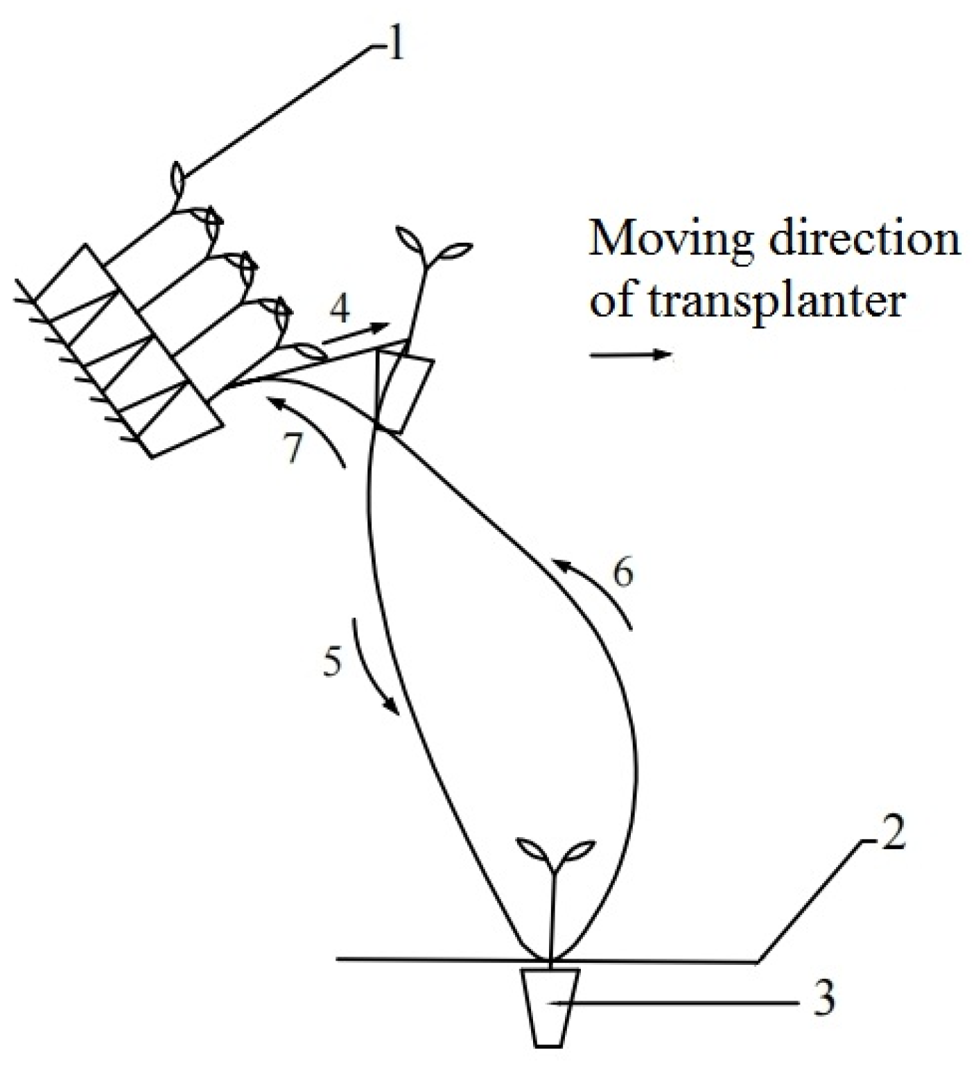
2.1. Backward Transplanting Movement Trajectory Planning

The transplanting mechanism of the pepper hole tray seedlings adopted a backwards transplanting trajectory. The direction of the seedling picking mechanism was opposite to the advance direction of the transplanter. After completing a transplanting process, the seedling picking mechanism would reach the next seedling picking point along with the movement of the transplanter. There was no need to bypass the planted hole tray seedling.
A complete transplanting cycle for the backward transplanting of the pepper hole tray included four stages: picking the seedling, holding the seedling, planting the seedling and returning. The seedling movement trajectory was planned as shown in Figure 1.
In order to realize the smooth process of transplanting, the seedling movement trajectory was planned. Upon reaching the position of the seedling picking point, the grippers simulated a human hand action and clamped the hole tray seedling stem along the clamping seedling trajectory (7). Next, the seedling picking action was completed along the seedling picking trajectory (4). After the hole tray seedling was successfully removed, the seedling holding stage was completed along the holding seedling trajectory (5). The hole tray seedling was maintained upright during holding until being transplanted at the planting point (3).

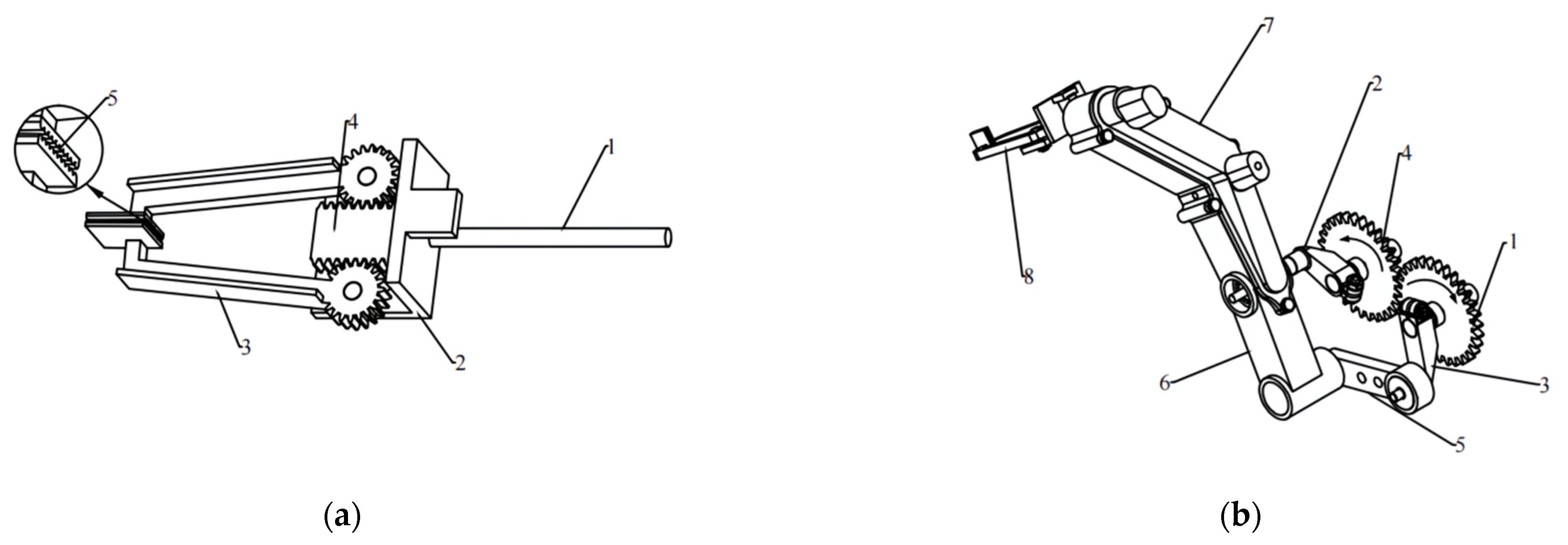
2.2. Working Principle and Mechanical Design

The integrated automatic transplanting mechanism designed in this paper is shown in Figure 2. It consisted of a flexible clamp mechanism and a double-crank linkage mechanism. The flexible clamp mechanism was the end actuator to clamp and hold the hole tray seedlings during the transplanting process. As shown in Figure 2a, under the action of the CAM, the push rod pushed the rack to complete the reciprocating movement. The rack meshed with the gear to drive the clamping grippers to open and close, and completed the clamping and releasing action.
The double-crank linkage mechanism was an important part to realize the seedling movement trajectory. As shown in Figure 2b, the double-crank linkage mechanism mainly included: the spur gears, the crank, the connecting rod, and the clamping mechanism. The spur gear had a transmission ratio of 1. Gear (1) was connected with the drive shaft and rotated clockwise around the center of the circle. Gear (4) rotated counterclockwise around its center. Connecting rods were fixed with the two gears, respectively, serving as the crank (2) and (3) of the double-crank linkage mechanism, and rotating the gears in the opposite direction with the rotation of the gear. The connecting rods (5) and (6) were driven by the cranks. They were reciprocated in a plane following a certain trajectory and the degree of freedom of the whole rod mechanism was 2. The connecting rod (7) and the clamping mechanism (8) were always maintained at a fixed angle and could be regarded as one. The trajectory that formed at the end point of the clamping mechanism (8) during the movement cycle was the seedling movement trajectory.

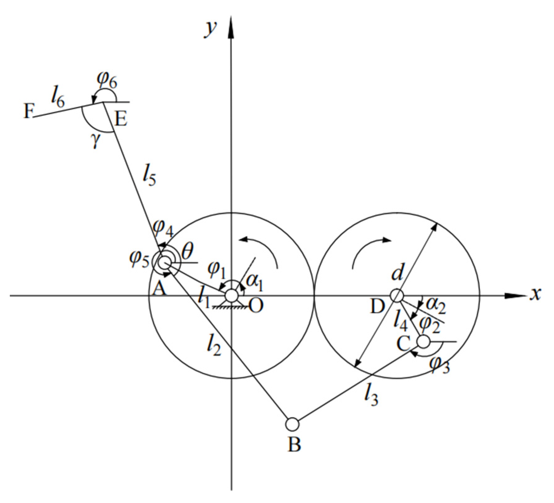
2.3. Kinematic Equation of the Integrated Automatic Transplanting Mechanism

We established the cartesian coordinates system, as shown in Figure 3. The transmission ratio of the two spur gears was 1 and the rate relationship was constant. We took the rotation center of the left gear as the origin O. The horizontal direction was the x-axis and the vertical direction was the y-axis. The known constants were the diameters of the two spur gears, the included angle between AE and EF, and the included angle between AB and AE. The parameters to be optimized were the initial phase angles of the crank OA and DC and the lengths of each connecting rod. From the variation of the angle of the crank rotation at each moment, we defined the involved angle as counterclockwise in the positive direction.
The displacement equation for point A is as follows:
x A = l 1 cos α 1 + φ 1 y A = l 1 sin α 1 + φ 1
where l1 is the length of the crank OA (mm); α1 is the initial phase angle of crank OA (°); and φ1 is the angle of rotation of the crank OA at each moment (°).
The displacement equation for point C:
x C = d + l 4 cos α 2 φ 2 y C = l 4 sin α 2 φ 2
where l4 is the length of crank DC (mm); α2 is the initial phase angle of crank DC (°); φ2 is the angle of rotation of the crank DC at each moment (°); and d is the diameter of the gear.
According to the vector relationship: O A + A B = O D + D C + C B .
The Displacement Equation for point C:
x B = x A + l 2 cos φ 5 = x C + l 3 cos φ 3 y B = y A + l 2 sin φ 5 = y C + l 3 sin φ 3
where l2 is the length of rod AB (mm); l3 is the length of rod BC (mm); φ5 is the angle of rod AB (°); and φ3 is the angle of rod BC (°). Thus, a = l2, b = l3, c 1 = d + l 4 cos α 2 φ 2 l 1 cos α 1 + φ 1 ; c 2 = l 4 sin α 2 φ 2 l 1 sin α 1 + φ 1 .
Equation (3) could be simplified as:
a cos φ 5 b cos φ 3 = c 1 a sin φ 5 + b sin φ 3 = c 2
Equation (4) could be simplified as:
cos φ 5 = sin ( arcsin a 2 c 1 2 c 2 2 b 2 2 b c 1 2 + c 2 2 arctan c 2 c 1 ) cos φ 3 = c 1 + a c o s φ 5 b
Then, φ3, φ4 could be expressed by φ2, φ1 and, bringing Equation (5) into Equation (3), we obtained the displacement equation for point B:
x B = l 4 cos α 2 + φ 2 + l 3 cos π φ 3 y B = l 4 sin α 2 + φ 2 + l 3 sin π φ 3
φ 4 = θ 2 π φ 5
The displacement equation for point C:
x E = x A + l 5 cos φ 4 y E = y A + l 5 sin φ 4
φ 6 = π + φ 4 γ
φ 4 = θ 2 π φ 5
where l5 is the length of rod AE (mm); φ4 is the angle of rod AE (°); φ5 is the angle of rod AB (°); and γ is the angle between AE and EF (°).
The displacement equation for point F:
x F = x A + l 5 cos φ 4 + l 6 cos φ 6 y F = y A + l 5 sin φ 4 l 6 sin φ 6
where l5 is the length of rod AE (mm); φ4 is the angle of rod AE (°); l6 is the length of rod EF (mm); and φ6 is the angle of rod EF (°).
Equations (1), (2) and (6)–(8) could obtain the velocity and acceleration equations of each member by taking the first and second derivative of time t.
The velocity equation of point F:
x F = x A + l 5 sin φ 4 φ 4 l 6 sin φ 6 φ 6 y F = y A + l 5 sin φ 4 φ 4 l 6 cos φ 6 φ 6
where x A and y A are the horizontal and vertical coordinates of the velocity at point A, (mm/s); x F and y F are the horizontal and vertical coordinates of the velocity at point F, (mm/s); φ 4 is the first derivative of the angle of rod AE, (rad/s); and φ 6 is the first derivative of the angle of rod EF (rad/s).
Acceleration equation for point F:
x F = x A + l 5 sin φ 4 φ 4 + sin φ 4 φ 4 l 6 sin φ 6 φ 6 + cos φ 6 φ 6 y F = y A + l 5 cos φ 4 φ 4 sin φ 4 φ 4 l 6 cos φ 6 φ 6 sin φ 6 φ 6
where x A and y A are the horizontal and vertical coordinates of the velocity at point A, (mm/s); x F and y F are the horizontal and vertical coordinates of the velocity at point F, (mm/s); x A and y A are the horizontal and vertical coordinates of the acceleration at point A (mm/s2); x A and y A are the horizontal and vertical coordinates of the acceleration at point A (mm/s2); φ 4 is the first derivative of the angle of rod AE (rad/s); φ 6 is the first derivative of the angle of rod EF (rad/s); φ 4 is the first derivative of the angle of rod AE, (rad/s2); and φ 6 is the first derivative of the angle of rod EF (rad/s2).

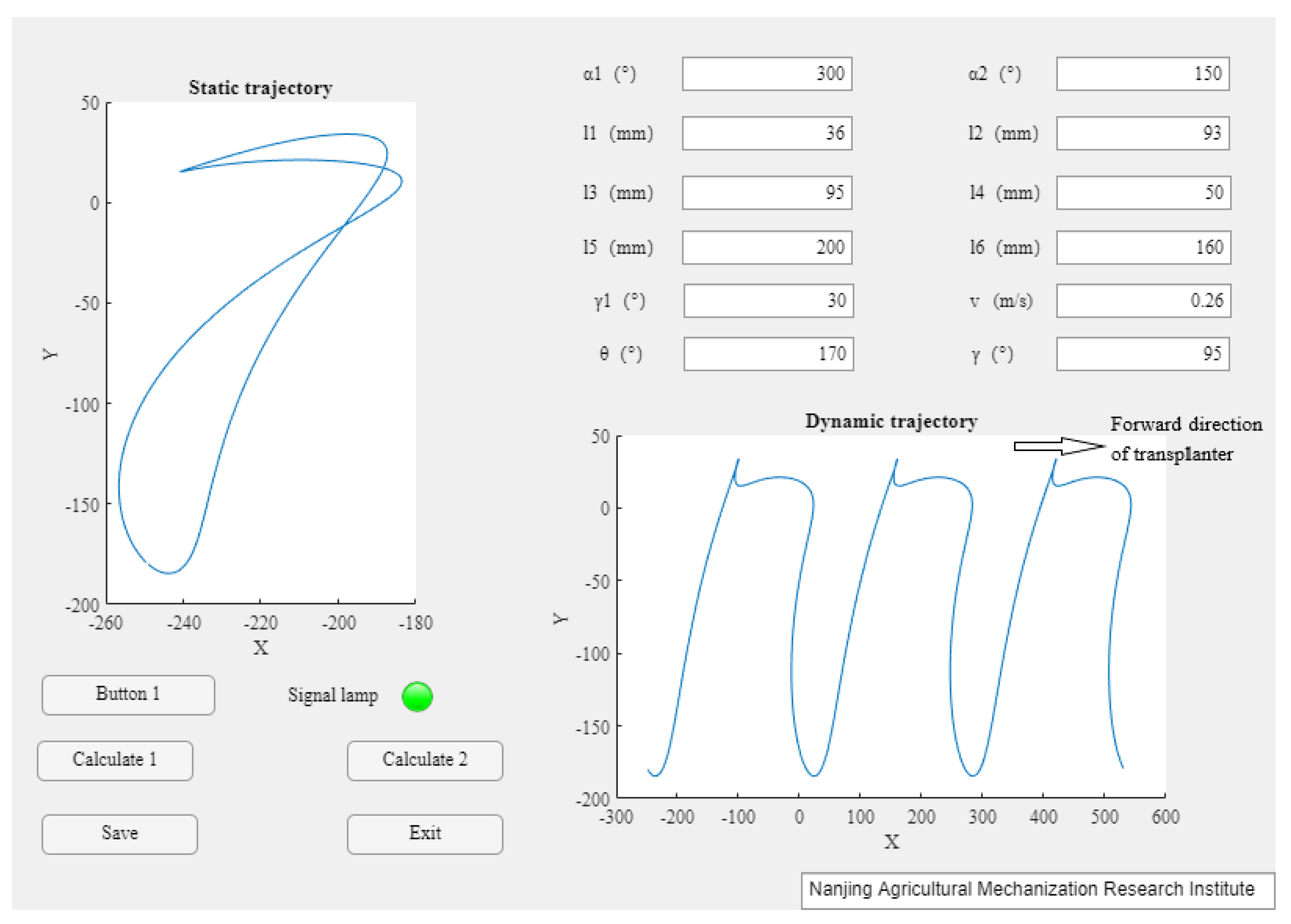
2.4. Motion Trajectory Optimization Objective

According to the agronomic requirements of pepper transplanting operations, the transplanting distance was about 260 mm and the speed of the transplanter matched the pepper transplanting distance. We set the speed of the transplanter to 0.26 m/s.
Based on the kinematic equation of the integrated transplanting mechanism, the parameter optimization program was prepared using App Designer in MATLAB software, as shown in Figure 4. The parameter optimization program interface of the clamping stem seedling picking mechanism was mainly divided into three parts.
Part 1: We input the parameter value of each variable. Then, we clicked the Button 1 to determine the condition of the crank. If the input rod length met the conditions of the double crank, and the Signal Lamp would appear in green. If it did not meet the requirements, the Signal Light did not come on.
Part 2: After inputting the parameters, we clicked Calculate 1 and Calculate 2 to obtain the static trajectory and dynamic trajectory of the transplanting process, respectively.
Part 3: Finally, we clicked the Save button to import the optimized parameter values into the Excel table and clicked the Exit button to exit the program.

2.5. High-Speed Photography Test Method

According to the parameter optimization results in Table 1, the design and assembly of the pepper clamping stem seedling picking mechanism was completed in SolidWorks. we carried out the prototype and set up an automatic seedling transplanting test platform. The high-speed camera used in this study had a resolution of 1280 × 1024 and a frame rate of 1000 frames. The actual trajectory of the end point of the seedling picking mechanism during the transplanting operation cycle was collected by high-speed camera technology.

3. Results

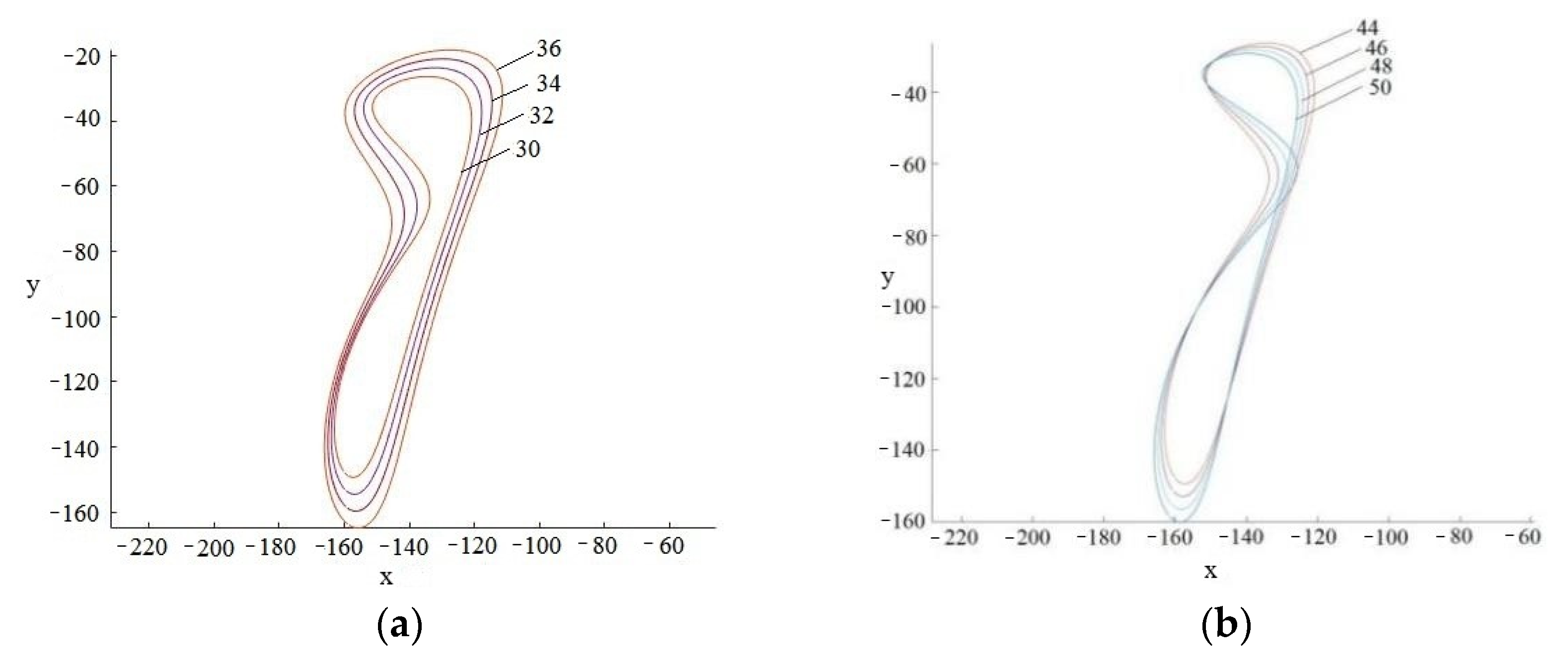
3.1. Effect of Parameter Changes on the Seedling Trajectory

The parameter optimization program of the clamping stem seedling picking mechanism in Figure 4 was used to optimize the relevant parameters affecting the seedling’s movement trajectory. A single-variable control method was used to analyze the influence of single-parameter changes on the seedling movement trajectory. According to experience, each parameter was assigned to the initial value. On the basis of the initial value, only one parameter was changed each time. The parameters were constantly adjusted and optimized and finally the optimum parameters were obtained.
The results of the parameter analysis are shown in Figure 5.
According to Figure 5a, by increasing the length of lOA the trajectory height gradually increased. This showed that changing the length of lOA would cause significant changes to the height of the trajectory. Figure 5b shows that the trajectory height did not change significantly by increasing of the length of lCD, but the overall trajectory moved down. Figure 5c shows that changes to the length of lBC did not cause a significant change in the trajectory height, but the overall trajectory moved upward. Figure 5d shows that the larger the length of lAB, the narrower the shape of the trajectory. The height of the overall trajectory became longer, but the picking seedling trajectory became shorter. Figure 5e shows that changing the length of lAE caused significant changes to the trajectory height. The larger the length of lAE, the narrower the shape of the trajectory. The results of Figure 5f show that the influence of changing the length of lEF was mainly reflected in the position of the seedling taking point: it had no effect on the trajectory height. When the length of lEF increased, the overall trajectory was shifted to the lower left.
In addition to the crank and connecting rod length affecting the seedling trajectory, the angle changes in the mechanism parameters also affected the trajectory shape. Figure 5g shows the effect of the angle θ between rod AE and rod AB on seedling trajectory. As the angle increased, the trajectory height was largely unchanged, but the overall trajectory shifted to the upper right. Figure 5h shows the effect of the angle γ between rod AE and EF on seedling trajectory. As the angle γ increased, the trajectory height remained unchanged, but the overall trajectory was translated to the lower right. Figure 5i,j show the effects of the initial angles of the crank DC and crank OA on the seedling movement trajectory, respectively. The trajectory height gradually decreased as the initial angle increased.

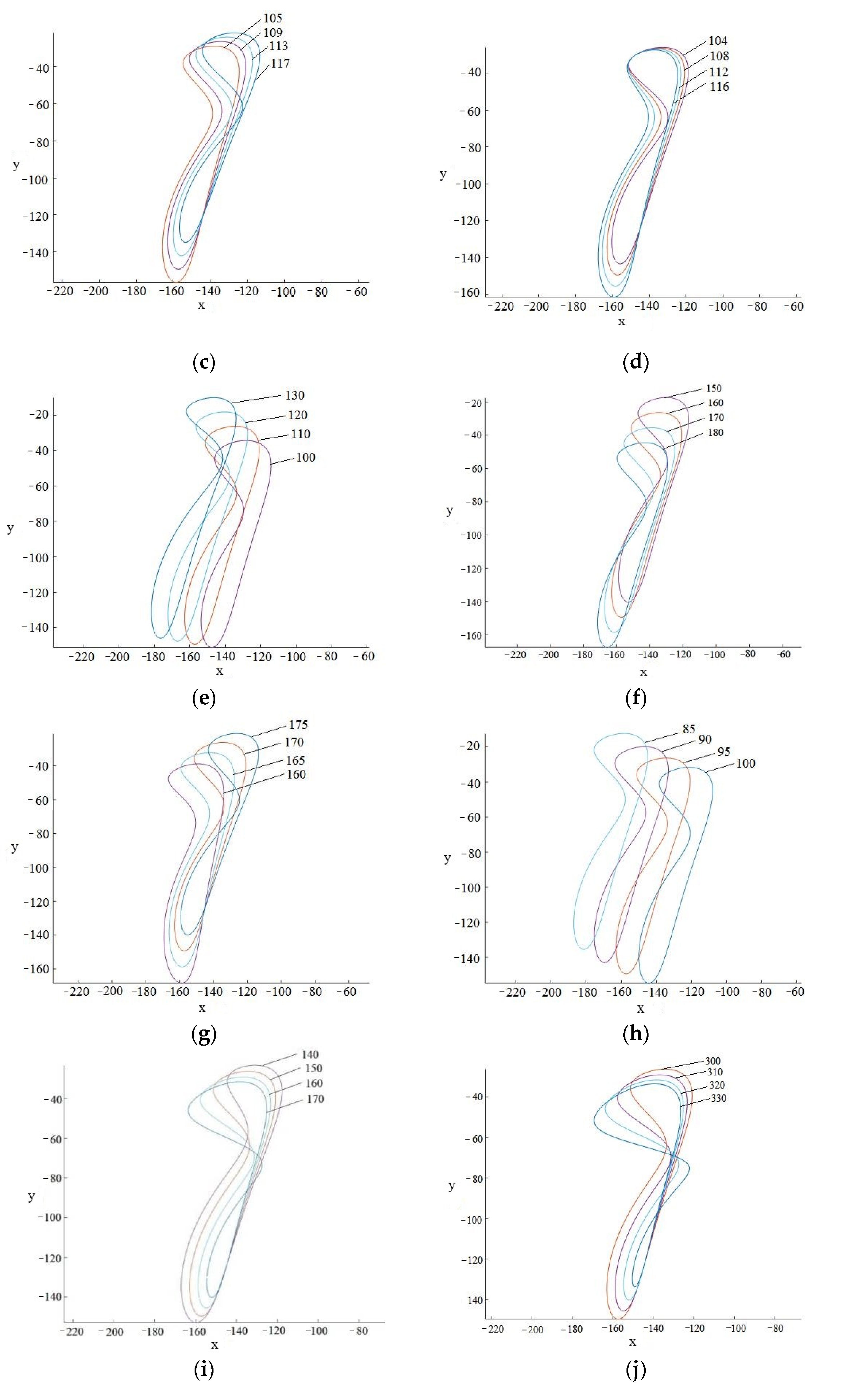
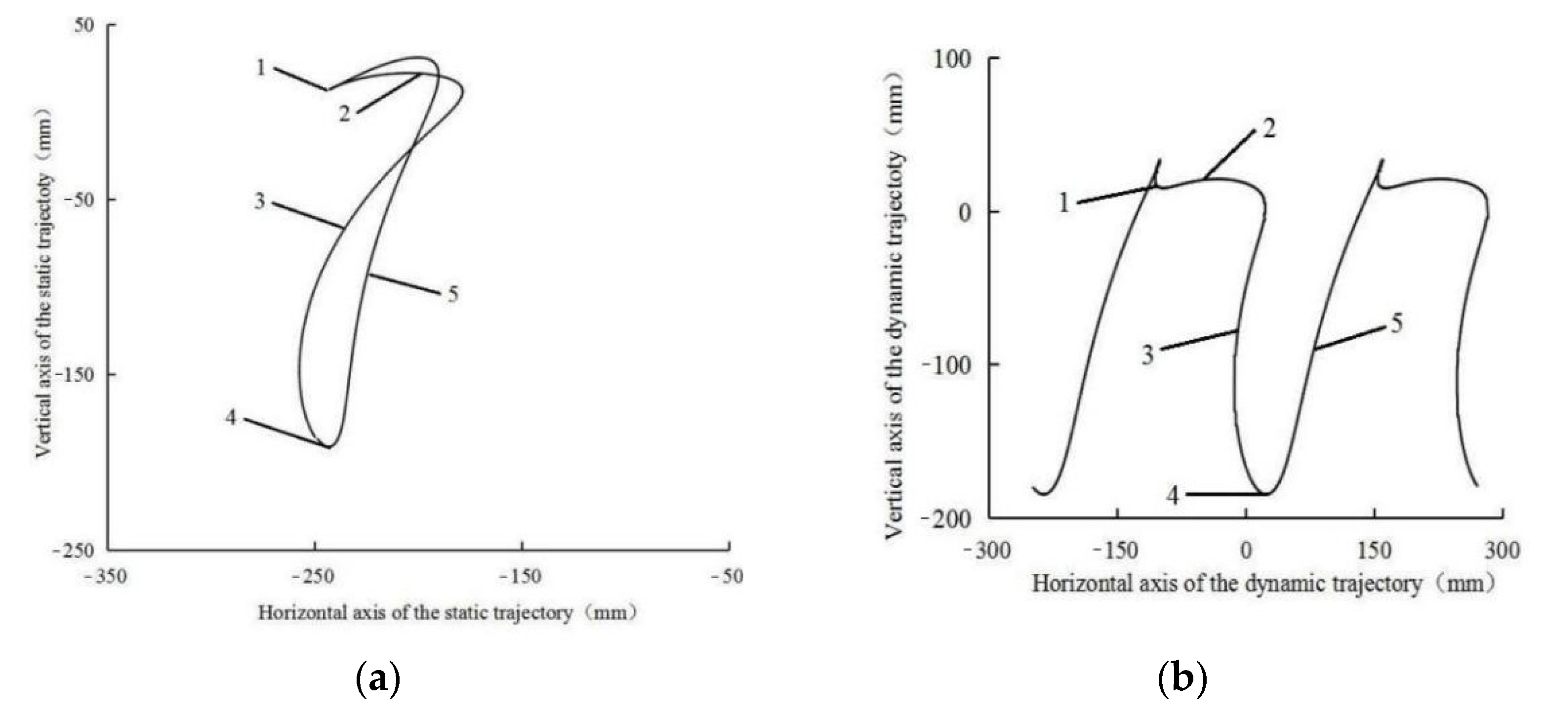
3.2. Optimization Results and Ideal Seedling Movement Trajectory

According to the working characteristics of the integrated transplanting mechanism of clamping stems, a seedling movement trajectory that met the requirements of backward transplanting was designed. The trajectory was planned as follows:
1. It needed to meet the requirements of monotonicity and the working conditions of the double-crank mechanism to avoid an unreasonable position and to ensure this did not affect the formation of the seedling movement trajectory;
2. The trajectory length of the seedling picking stage needed to be greater than the height of the hole tray (not less than 45 mm), otherwise the hole tray seedling would interfere with the mechanism. In addition, the trajectory height needed to be greater than 200 mm;
3. According to the agronomic requirements of pepper transplanting, the height difference between the seedling point and the planting point needed to be greater than 150 mm. In order to ensure the qualified rate of planting, the planting angle needed to be greater than 55°.
According to the changes to the mechanism parameters and the trajectory optimization plan, the parameters of the seedling mechanism were optimized by the trial-and-error method. The optimal combination of parameters was obtained by using the parameter optimization program of the clamping stem seedling picking mechanism. The optimized parameters are shown in Table 1.
Figure 6a shows the optimized static trajectory. The trajectory was shaped like a beak. Point 1 in the figure is the seedling picking point and Curve 2 is the trajectory of the seedling picking stage. The length of the trajectory of the seedling picking stage was greater than 45 mm, which met the requirement that the trajectory length of the seedling picking stage was greater than the height of the hole tray in the optimization plan. Curve 3 shows the trajectory of the seedling holding stage, and it can be seen that the seedling trajectory was smooth. Point 4 is the planting point, and Curve 5 shows the quick return stage to save transplanting time.
The height of the whole seedling movement trajectory reached 220.8 mm and the height difference between seedling picking point and planting point was 178.4 mm. The seedling picking angle was 21.03° and the planting angle was 64.15°. These optimization results met the agronomic requirements of pepper transplanting.
Figure 6b shows the optimized dynamic trajectory. The transplanter direction of the backward transplanting was in the positive direction of the x-axis. The optimized dynamic trajectory was in an n shape. Point 1 and Point 4 are the seedling picking point and planting point, respectively. Curve 2 and Curve 3 are the seedling picking and seedling holding stages. It can be seen that the whole trajectory was smooth without mutation. The next stage of seedling picking was carried out after the return stage. The distance between the adjacent planting points was 260 mm, which met the requirements of plant distance for pepper transplanting.

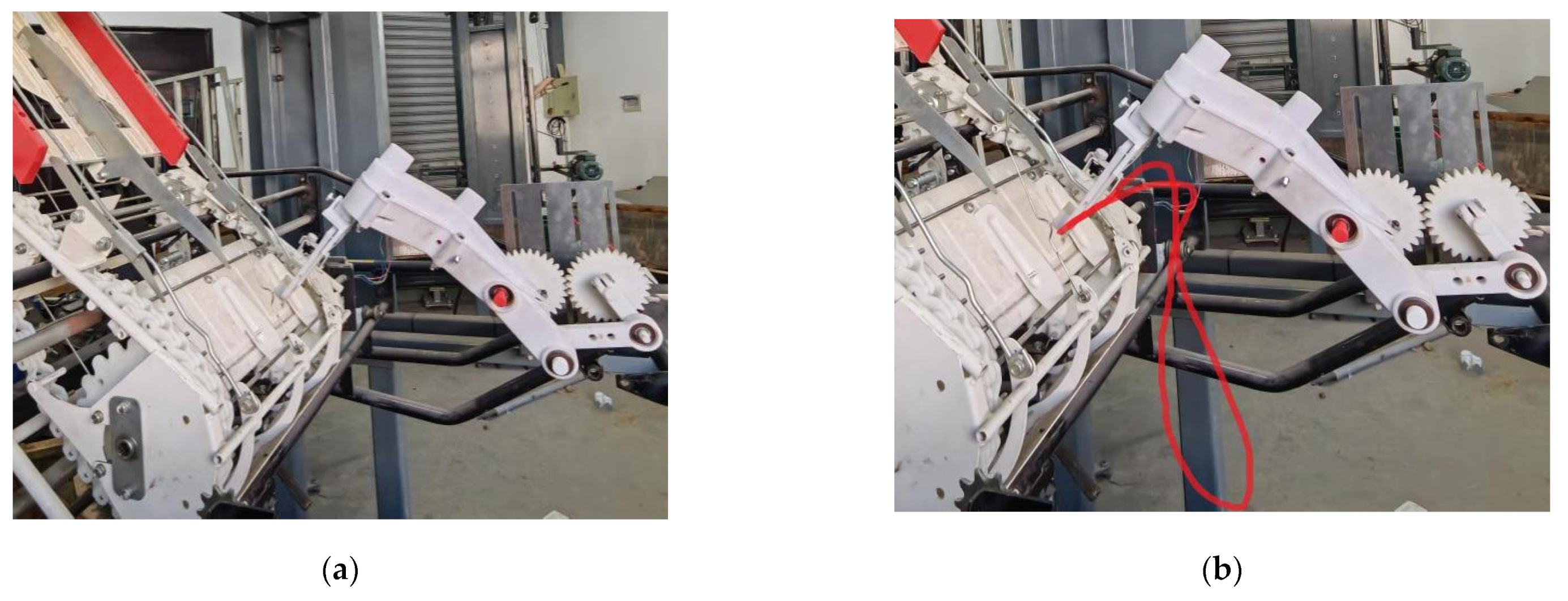
3.3. The Results of the High-Speed Photography Test

We set the rotation speed of the seedling picking mechanism at 60 r/min. After the camera debugging was stable, the trajectory was collected, and the actual trajectory of the seedling picking mechanism was obtained. The red trajectory shown in Figure 7b is the actual trajectory of the end point of the seedling picking mechanism during the transplanting operation cycle. The actual trajectory was compared with the static trajectory after optimization, and the results showed that the trajectory height and shape of the two trajectories were basically consistent, which verified the rationality and feasibility of the parameter optimization program.

3.4. Seedling Picking and Planting Test

The seedling planting test parameters in Table 2 were determined according to the industry standards of NY T3486-2019 [29] and JB-T10291-2013 [30]. We carried out seedling picking and planting tests, as shown in Figure 8. Under the condition that the rotation speed of the seedling picking mechanism was set at 60, 70 and 80 times/min, the continuous seedling picking and planting situation was tested 60 times, respectively. The test results are shown in Table 2 and the transplanting quality of the seedling picking mechanism was evaluated.

4. Discussion

At present, automatic pepper transplanting machines have the problems of low seedling picking success rate and low seedling planting success rate [4]. The main reason for the low success rate of seedling picking is that the main seedling picking mechanism used is the clamping bowl type [8,9,10]. The unreasonable design of the seedling trajectory makes it impossible to accurately clamp the substrate. The main reason for the low seedling planting success rate is that the automatic pepper transplanting mechanism adopts forward transplanting. This type of machine needs to meet the height requirements of the seedling picking mechanism, which can affect the seedling planting success rate. Based on the strong characteristics of pepper seedlings, this paper aimed to identify a design that could accurately clamp the stems and improve the seedling planting success rate. In previous works of research, MATLAB was often used to optimize the static trajectory of the seedling picking movement [16]. On this basis, we developed the parameter optimization program of the clamping seedling picking mechanism, which not only optimizes the static and dynamic trajectory of the seedling picking mechanism, but also optimizes the parameters of the seedling picking mechanism. In order to improve the rate of planting uprightness, we propose the backward transplanting method, which does not need to meet the aforementioned height requirements. This way avoids knocking down the pots after they are planted by the seedling picking mechanism. Ultimately, the trajectory design is more reasonable. The height of the whole seedling movement trajectory is 220.8 mm, and the height difference between the seedling picking point and the planting point is 178.4 mm. The seedling picking angle is 21.03°, and the planting angle is 64.15°. These optimization results meet the agronomic requirements of pepper transplanting.
According to the results of the seedling picking and planting test, the success rate of seedling picking and planting were 94.7% and 84.2% when the rotation speed of the seedling picking mechanism was 60 r/min. At the speed of 80 r/min, the seedling picking success rate was 91.1%, and the planting success rate was 78.5%. In this study, the seedling picking mechanism was a double-crank connecting mechanism. However, we found that the rotation speed of the mechanism caused vibrations and affected the quality of transplanting. In the future, by studying the working principle of various types of mechanisms, we will design a seedling taking mechanism with better reliability and improve the frequency of transplanting. In addition, we will further optimize the automatic seedling transplanting mechanism for pepper hole tray seedlings.

5. Conclusions

In this study, we designed and integrated an automatic transplanting mechanism based on clamping stem seedling picking, and established a kinematic model of the double-crank connecting rod type to optimize seedling picking. We also designed a parameter optimization program for the clamping stem seedling picking mechanism and analyzed the effect of the length of each rod and related angle in the mechanism on the seedling trajectory.
Using parameter optimization, we optimized a group of ideal mechanism parameter combinations. The static trajectory of beak shape and the dynamic trajectory of n shape met the requirements of backward transplanting. The optimized mechanism parameters were as follows: crank lOA = 36 mm, crank lCD = 50 mm; rod lAB = 93 mm, rod lBC = 95 mm; rod lAE = 200 mm, rod lEF = 160 mm, θ = 170°, γ = 95°, α1 = 300°, α2 = 150°.
Based on the optimized mechanism parameters, SolidWorks was used for 3D modeling. We built a prototype for the high-speed camera test. From the test results, the actual static trajectory and dynamic trajectory were basically consistent with the static trajectory and dynamic trajectory generated by MATLAB. We proved the feasibility of the of clamping stem seedling picking mechanism using the parameter optimization program.
We designed a seedling picking and planting test. Under the operation frequency of 80 r/min, the success rate of seedling selection was more than 91.1%, and the success rate of planting was more than 78.5%. The qualified rate of erect degree was about 90% and the coefficient of the variation of plant spacing was stable below 14.1%. The results showed that the integrated automatic transplanting mechanism based on the clamping stem could meet the actual transplanting needs.

Author Contributions

Conceptualization, S.H. and M.H.; methodology, S.H. and M.H.; software, S.H. and M.H.; validation, W.Y., S.H. and M.H.; formal analysis, W.Z.; investigation, W.Z.; resources, S.H.; data curation, M.H.; writing—original draft preparation, S.H.; writing—review and editing, W.Y.; visualization, W.Y.; supervision, M.H. All authors have read and agreed to the published version of the manuscript.

Funding

This research was funded by the key tasks of Nanjing Agricultural Mechanization Research Institute, Ministry of Agriculture and Rural Affair(Grant No. CAAS-NRAM-SJ-201903).

Institutional Review Board Statement

Not applicable.

Informed Consent Statement

Not applicable.

Data Availability Statement

The datasets used and/or analyzed during the current study are available from the corresponding author on reasonable request.

Conflicts of Interest

The authors declare no conflict of interest.

References

  1. Wang, J.; Yang, S.; Zhang, X. The situation and thinking of Chinese characteristic vegetable industry. Chin. Veg. 2020, 6, 1–5. [Google Scholar]
  2. Zheng, J.; Li, X.; Liu, F.; Zhou, S.; Luo, F.; Ma, Y. Advances in Pepper Science in 2017. Chin. Veg. 2018, 5, 9–15. [Google Scholar]
  3. Xiao, C.; Kuang, B.; Yu, X.; Shang, Q.; Tang, E.; Li, J. Advantages and key technologies of hole dish seedling of solanaceous vegetables. Shanghai Veg. 2020, 2, 21–22. [Google Scholar]
  4. Yue, J.; Guo, J.; Linag, J.; Liang, S.; Zhang, C.; Liu, Y.; Liu, M. The Development Status of Transplanting Machinery at Home and Abroad. Xinjiang Agric. Mech. 2016, 5, 30–32, 36. [Google Scholar]
  5. Jin, X.; Li, S.; Yang, X.; Yan, H.; Wu, J.; Sun, X.; Zhang, M. Motion Analysis for Vegetable Potted Seedling Pick-up Mechanism with Double Crank Geared Linkages. J. Agric. Mech. Res. 2014, 7, 13–17. [Google Scholar]
  6. Zhang, M.; Ji, J.; Du, X. Status and Prospect of Transplanter at Home and Abroad. Agric. Eng. 2012, 2, 21–23. [Google Scholar]
  7. Zhou, M.; Xu, J.; Tong, J.; Yu, G.; Zhao, X.; Xie, J. Design and experiment of integrated automatic transplanting mechanism for taking and planting of flower plug seedlings. Trans. CSAE 2018, 34, 44–51. [Google Scholar]
  8. Zhao, Y.; Zhang, W.; Xin, L.; Xie, J.; Xue, X.; Shan, Y. Design and Experiment of Extensible Potted Tomatoes Seedling Transplanting Mechanism. Trans. CSAM 2019, 50, 105–112. [Google Scholar]
  9. Xie, S.; Yang, S.; Liu, J.; Song, L.; Xie, Q.; Duan, T. Development of the seedling taking and throwing device with oblique insertion and plug clipping for vegetable transplanters. Trans. CSAE 2020, 36, 1–10. [Google Scholar]
  10. Zhao, X.; Cui, H.; Dai, L.; Xu, Y.; Wang, C.; Shen, J. Optimal design and experiment of hybrid-driven five-bar flower potted-seedling transplanting mechanism. Trans. CSAE 2017, 33, 34–40. [Google Scholar]
  11. Zhang, Z.; Zhang, N.; Lv, Q.; Han, C.; Xu, H.; Li, H.; Bai, Z. Design and Research on the Automatic Transplanting Machine of the Top Pinch Combined Type Plug Seedling. Xinjiang Agric. Mech. 2016, 6, 16–18, 45. [Google Scholar]
  12. Wang, D.; Jin, X.; Ji, J.; He, Z.; Yan, H. Design and Experiment of Fully Automatic Ejection and Picking-up Seedlings Mechanism of Transplanter. J. Agric. Mech. Res. 2016, 10, 64–68. [Google Scholar]
  13. Wen, Y.; Zhang, J.; Zhang, Y.; Tian, J.; Yuan, T.; Tan, Y.; Li, W. Development of insertion and ejection type seedling taking device for vegetable plug seedlings. Trans. CSAE 2020, 36, 96–104. [Google Scholar]
  14. Liao, Q.; Zhang, Z.; Hu, Q.; Xu, B. Design and Trajectory Analysis of Pneumatic Picking-up Mechanism for Rape Paper Pot Seedling. Trans. CSAM. 2017, 48, 70–78. [Google Scholar]
  15. Han, L.; Mao, H.; Zhao, H.; Liu, Y.; Hu, J.; Ma, X. Design of root lump loosening mechanism using air jets to eject vegetable plug seedlings. Trans. CSAE 2019, 35, 37–45. [Google Scholar]
  16. Han, Z.; Yan, H.; Chen, K.; He, Y. Design and Parameter Optimization of Seedling Expeller Mechanism Based on Matlab. J. Agric. Mech. Res. 2017, 39, 142–146. [Google Scholar]
  17. Sun, L.; Shen, J.; Zhou, Y.; Ye, Z.; Yu, G.; Wu, C. Design of non-circular gear linkage combination driving type vegetable pot seedling transplanting mechanism. Trans. CSAE 2019, 35, 26–33. [Google Scholar]
  18. Li, H.; Cao, W.; Li, S.; Liu, J.; Chen, B.; Ma, X. Development of 2ZXM-2 automatic plastic film mulching plug seedling transplanter for vegetable. Trans. CSAE 2017, 33, 23–33. [Google Scholar]
  19. Ye, B.; Yu, G.; Chen, Z.; Zhao, Y. Kinematics modeling and parameters optimization of seedling pick-up mechanism of planetary gear train with eccentric gear and non-circular gear. Trans. CSAE 2011, 27, 7–12. [Google Scholar]
  20. Guo, J.; Huang, Y.; Dai, Y.; Luo, X.; Gou, H. Performance experimental study of orderly rows seedlings on a type of seedling-falling device with air blast. J. Chin. Agric. Mech. 2014, 35, 136–138. [Google Scholar]
  21. Ma, X.; Li, H.; Ge, Y.; Li, S.; Zhao, Y.; Yu, S. Experimental Study on Mechanical Properties of Tomato Seedling Stem. J. Agric. Mech. Res. 2020, 42, 161–167. [Google Scholar]
  22. Liang, L.; Guo, Y. Correlation study of biomechanical properties and morphological characteristics of crop stalks. Trans. CSAE 2008, 24, 1–6. [Google Scholar]
  23. Shuangyan, H.; Minjuan, H.; Wenyi, Z.; Zhan, J. Experimental and simulation study on mechanical properties of stem of pepper hole seedlings. J. Chin. Agric. Mech. 2022, 43, 9–17. [Google Scholar]
  24. Li, H.; Ma, X.; Cao, W.; Li, S.; Zhou, W. Design and experiment of seedling picking mechanism by stem clipping for tomato plug seedling. Trans. CSAE 2020, 36, 39–48. [Google Scholar]
  25. Li, H.; Cao, W.; Li, S.; Fu, W.; Liu, K. Kinematic analysis and test on automatic pick-up mechanism for chili plug seedling. Trans. CSAE 2015, 23, 20–27. [Google Scholar]
  26. Jiang, L.; Wu, C.; Tang, Q.; Zhang, M.; Wang, G. Kinematics model and parameter optimization of planting process of rape carpet seedling transplanter. Trans. CSAE 2018, 34, 37–46. [Google Scholar]
  27. Shang, T.; Yuan, R.; Tian, C.; Wang, X. Parameters matching and optimization of seedling pick-up mechanism with crank-rocker planetary gear train. J. Cent. South Tech Univ. 2016, 2, 443–449. [Google Scholar]
  28. Tong, J.; Yu, G.; Zhu, Y.; Ye, B.; Zheng, C.; Huang, J. Design and Experiment of Three-arms Rotary Vegetable Plug Seedling Pick-up Mechanism. Trans. CSAM 2019, 50, 113–121. [Google Scholar]
  29. NY/T3486-2019; Ministry of Agriculture and Rural Affairs of the People’s Republic of China, Operation Quality of Vegetable Transplanter. National Technical Committee on Agricultural Machinery of Standardization Administration. China Agriculture Press: Beijing, China, 2019.
  30. JB/T 10291-2013; China Machinery Industry Federation, Dryland Planting Machinery. National Technical Committee on Agricultural Machinery of Standardization Administration. AMST: Beijing, China, 2013.
Figure 1. Backward transplanting movement trajectory planning: 1—hole tray seedling; 2—ground; 3—planting point; 4—picking seedling; 5—holding seedling; 6—returning; 7—clamping seedling.
Agriculture 12 00557 g001
Figure 2. The automatic transplanting mechanism. (a) Flexible clamping mechanism. 1—Push rod; 2—rack mounting plate; 3—gripper; 4—rack; 5—wavy inner side. (b) Double-crank linkage mechanism. 1, 4—spur gear; 2, 3—crank; 5, 6, 7—connecting rod; 8—clamping mechanism.
Agriculture 12 00557 g002
Figure 3. Motion diagram of double crank linkage mechanism.
Agriculture 12 00557 g003
Figure 4. Parameter optimization program of clamping stem seedling picking mechanism.
Agriculture 12 00557 g004
Figure 5. Effect of parameter changes on seedling picking trajectory: (a) effect of crank OA length on trajectory; (b) effect of crank CD length on trajectory; (c) effect of rod BC length on trajectory; (d) effect of rod AB length on trajectory; (e) effect of rod AE length on trajectory; (f) effect of rod EF length on trajectory; (g) effect of the angle between AE and AB on trajectory; (h) effect of the angle between AE and EF on trajectory; (i) effect of the initial angles of the crank DC; (j) effect of the initial angles of the crank OA.
Agriculture 12 00557 g005aAgriculture 12 00557 g005b
Figure 6. Trajectory of seedling picking after optimization: 1—The point of picking seedling; 2—The trajectory of clamping seedling stage; 3—The trajectory of holding seedling stage; 4—The point of planting seedling; 5—The trajectory of returning stage. (a) Static trajectory after optimization; (b) dynamic trajectory after optimization.
Agriculture 12 00557 g006
Figure 7. Actual trajectory of the seedling picking mechanism: (a) the prototype verification platform; (b) the actual seedling movement trajectory.
Agriculture 12 00557 g007
Figure 8. Seedling picking and planting test.
Agriculture 12 00557 g008
Table 1. Parameters of the seedling picking mechanism after optimization.
ParameterNameValue
lOAThe length of crank OA (mm)36
lCDThe length of crank CD (mm)50
lABThe length of rod AB (mm)93
lBCThe length of rod BC (mm)95
lAEThe length of rod AE (mm)200
lEFThe length of rod EF (mm)160
θThe angle of rod AE and AB (°)170
γThe angle of rod AE and EF (°)95
α1The initial angle of the crank OA (°)300
α2The initial angle of the crank CD (°)150
Table 2. Parameters of seedling picking and planting test.
Number of Hole Tray SeedlingsThe Rotation Speed (r/min)Number of Lack of SeedlingsNumber of Seedlings PickingThe Success Rate of Seedling Picking (%)Number of Seedlings PlantingThe Success Rate of Seedling Planting (%)Qualified Rate of Planting Uprightness (%)Coefficient of Variation of Plant Spacing (%)
606035494.74884.297.811.4
607025391.44781.095.713.8
608045191.14478.594.914.1
Publisher’s Note: MDPI stays neutral with regard to jurisdictional claims in published maps and institutional affiliations.

