Article

Simulation and Test of “Separated Burying Device” of Green Manure Returning Machine Based on the EDEM Software

1
College of Mechanical Electrification Engineering, Tarim University, Alar 843300, China
2
Agricultural Engineering Key Laboratory, Ministry of Higher Education of Xinjiang Uygur Autonomous Region, Tarim University, Alar 843300, China
3
College of Animal Science, Tarim University, Alar 843300, China
*
Author to whom correspondence should be addressed.
Agriculture 2022, 12(5), 569; https://doi.org/10.3390/agriculture12050569
Submission received: 17 March 2022 / Revised: 14 April 2022 / Accepted: 15 April 2022 / Published: 19 April 2022

Abstract

:
Today, China’s orchard area covers 11,874,850 ha. With China’s progress in implementing the strategy of “quality-based and environmental-friendly agricultural development”, green manure has been developed as a modernized green soil management method for use in orchard areas. Green manure shows the highest decomposition rate with a ploughing depth of 150 mm. To efficiently utilize green manure in orchard areas, a “separated burying device” was designed, which can realize “stalk falling and soil falling” simultaneously. The device was composed of rotary blades, an iron chain separation curtain, soil retaining board and compacting machine. The cooperation parameters of different parts of the proposed device were designed through a discrete element simulation test, and a cooperative parameter model of the proposed device was constructed. According to the simulation test, the highest coverage of the prototype (95.16%) was achieved only when the knife roller center of rotary tillage moved to the point where it had a horizontal distance of 378.76 mm from the root of the “iron chain separation curtain”, the width of the transverse soil retaining board was 187.78 mm and the included angle of the soil retaining board θ was 116.48°. Based on a model verification test, the burying rate was found to be 94.36%, which differed slightly from the simulation test results. The burying rate increased by 4.84% upon the application of a “separated burying device”. The “separated burying device” was able to increase the burying rate of green manure between rows in the orchard area. It is conducive to the full utilization of green manure resources and lays good sowing foundations for green manure resowing. The construction of a “separated burying device” and its cooperative parameter model can provide insight into the research, development and optimization of relevant machines, such as the stalk returning machine.

1. Introduction

Based on the data of the Natural Bureau of Statistics (China), China’s orchard area covered 10,681,020 ha. and 11,874,850 ha. in 2010 and 2019, respectively, while demonstrating a year-on-year growth of 10.05% [1,2]. The UN sustainable development summit in New York passed the 2030 Agenda, which explicitly defined the significance of sustainable development [3]. With China’s progress in implementing the strategy of “quality-based and environmental-friendly agricultural development”, green manure has been developed as a modernized green soil management method for use in orchard areas [4,5]. Green manure refers to green plants which are returned to the field directly, applied in places other than the planting area or fermented together as bio-fertilizers. Planting green manure can change the physical and chemical properties of soil, increase organic nutrients in the soil, and improve crop yields and quality [6,7,8,9]. South Xinjiang, China is close to the edges of the Taklimakan Desert, and it belongs to an extremely arid region. Typically, the orchard area soil is significantly lacking in nutrients. Due to superficial ploughing, the ploughing effect of green manure when it is returning to fields is poor, thus resulting in low utilization. However, deep ploughing could damage the surface roots of fruit trees, thus influencing their growth. With the rapid development of green manure planting in orchard areas, it is important to develop a device to improve the effect of green manure returning to the field.
Concerning the major utilization of green manure in orchard areas, it is used to cover and retain water in summer, while returning it to the field in autumn. In 1994, Tor Arvid Breland studied the decay of Trifolium repens and Trifolium pretense under different temperatures, which demonstrated quick decay at 0–20 cm [10]. In 2018, Lv Lixia et al. demonstrated that green manure crops such as Trifolium repens and ryegrass presented the highest decay rate for the ploughing depth of 10cm and slow decay for the paved surface [11]. The green manure returning machine has achieved rapid development, even though it was introduced late. In 2010, Rinieri Company (Italy) developed the ELX140 obstacle avoidance weeder for orchard areas [12]. Although this machine achieves high operational efficiency, the green manure utilization under coverage is lower than it is under burying. In 2012, Norremark et al. developed the inter-plant weeder, which utilized GPS positioning to recognize obstacles and plan paths. Even though the machine achieved a good coverage effect after operation, the cost was very high [13]. In 2021, Wu Huichang et al. also developed a GFY-200 green manure shattering-ploughing composite operation machine [14]. This machine was first utilized in pre-cutting and then implemented for the ploughing of rotary tillage, which improved operational efficiency. It is characteristic of high efficiency and energy-saving machines. However, the ploughing effect was not satisfactory. In 2020, the telescopic finger-type corn stalk rotary tillage buried machine was designed and developed by Yang Qinglu et al. [15] The prototype uses telescopic fingers and eccentric shafts to efficiently turn the crushed corn stalks over. The prototype can separate the straw and the soil and use the drop to make the straw fall first, and then the soil, so as to improve the effect of returning straw to the field. Van Wamel BV (Netherlands) and FENDT (Germany) also developed a green manure shattering-ploughing combined operation machine. However, the supporting system was higher than 220 kW and required forward power output. This type of green manure shattering-ploughing machine is large or mid-sized, costly and has poor matching with the power of micro-tractors in orchard areas [16,17,18]. Considering practical line spacing in orchard areas, green manure planting conditions and the economic level of fruit farmers, large-sized, high-cost green manure shattering-ploughing machines are not applicable for green manure returning operations.
At present, most Chinese scholars have carried out the overall design of the green manure returning prototype in the field of green manure returning to the field. At first, the superficial ploughing of green manure crops with high stalks may influence the burying effect. Moreover, deep ploughing may influence decay efficiency and can easily damage the surface roots of fruit trees. To address these problems, a “separated burying device” was designed, which can realize “stalk falling first, soil falling later, stalks below and soils up”. A discrete element simulation test of this device was carried out to determine cooperative relations among different parts. A new device is provided for efficient utilization of orchard green manure. Moreover, the feasibility and reliability of the design were demonstrated through a field test verification.

2. Materials and Methods

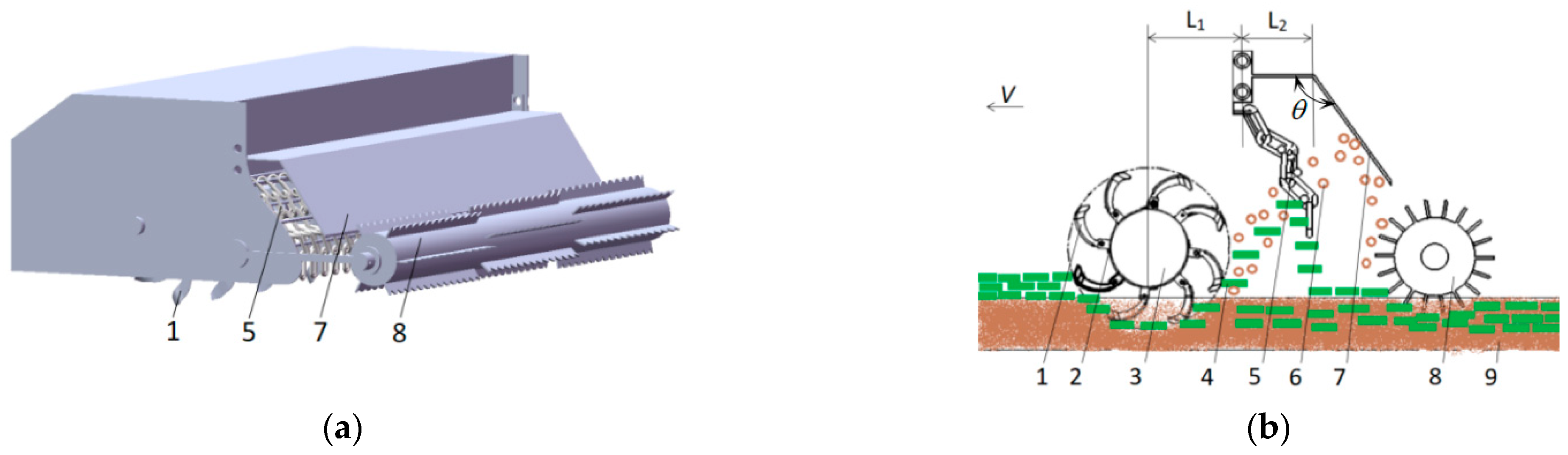
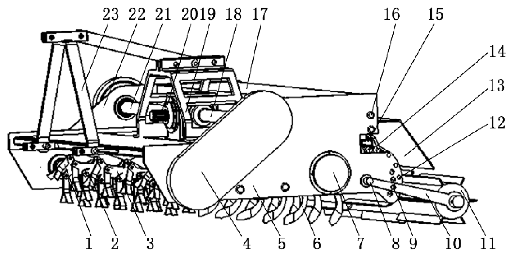
2.1. Composition and Working Principle of “Separated Burying Device”

The “separated burying device” is composed of rotary tillage cutters, iron chain separation curtain, soil retaining board and compacting machine (Figure 1a). To obtain a uniform load of cutter shaft and steady rotation during rotary tillage, all cutters were arranged in a dual-helix symmetric pattern. The “iron chain separation curtain” was composed of uniformly distributed iron chains which were fixed relatively through three locating rods, aiming to prevent dangers caused by interaction with the rotary tillage cutter during movement. However, iron chains can still sway within a small range to prevent the blockage caused by green manure stalks which are lifted by high-speed rotating cutters. The “iron chain separation curtain” was mainly used to separate the green manure stalks and soils. The soil retaining board was composed of a transverse plate and an inclined board. It was mainly used to block soil particles that pass through the “iron chain separation curtain”.
During operation, green manure stalks were ploughed into the soil partially by the rotary tillage cutter, while the rest was lifted by the rotary tillage cutter. Once the lifted part arrived at the “iron chain separation curtain” with soils, the stalks were blocked, and their trajectories were changed. They fell to the surface along with the “iron chain separation curtain”. However, soils passed through the “iron chain separation curtain” until they impacted onto the soil retaining board and then fell to the ground. In this way, the goal of “stalks falling first and soil falling later” was achieved. The remaining unburied green manure stalks were further compressed into the surface by the “stalk pressing plate” of the compacting machine. This ultimately increased the burying rate of stalks. The separation, ploughing and earthing principles are shown in Figure 1b.

2.2. “Iron Chain Separation Curtain” and Soil Retaining Board

The ‘iron chain separation curtain’ (Figure 2a) in the rotary tillage rear portion comprises a uniform configuration hoop and a chain through the three-locating rod, which is relatively fixed. The chain also helps avoid interference from the rotary cutter in the process of movement but can still shake within a small range. It is important to prevent the high-speed rotary tillage sword from throwing up green manure stems, which can adhere to and cause congestion on the chains. The main function of this device is to separate the green manure stem and soil thrown by the rotary tiller.
According to the crushing and returning experiment on orchard green manure, 90.1% of the crushing lengths lay between 0–100 mm, with the shortest length being 50 mm. To improve the service life of the chain, it should be ensured that the chain can slide between the positioning rod, preventing green fertilizer stalks from passing through the chain; therefore, the chain diameter is 14 mm, the inner length is 50 mm, and the outer width is 47.6 mm. The interval between the chains is 50 mm. According to the design of the entire machine, the working width is 1500 mm, and a total of 28 groups of chains are designed. Each set of chains consists of five iron rings, designed to radian such that the stalks slide slowly. There are three positioning rods in total, with a diameter of 10 mm. Two of them pass through the second and fourth iron rings, and one is pressed onto the third and fourth iron rings.
The soil retaining board (Figure 2b) comprises a horizontal plate and an inclined plate with the same length as the working width of 1500 mm. The width of the horizontal plate in the preliminary design is 150 mm and the width of the inclined plate is 300 mm. The main function of the retaining board is to block the soil particles passing through the ‘iron chain separation curtain’.
After cutting upturned soils, the rotary tillage cutter lifts soil and green manure stalk. Macroscopically, the soil can be distinguished as forward and backward lifting soil. The former falls after impacting onto the shell and then makes a secondary impact with the rotary tillage cutters, while lifting backwards [19]. Soil lifting performances are the key factor that influences the burying effect of green manure stalks. By neglecting air friction, the initial point coordinates of soil particles are found to be “x0, y0”. The speed along the x and y directions were expressed as va and ve, respectively, whereas the motion time was expressed as “t”. The gravitational acceleration (g) was determined to be 9.8 m/s. The lifting motion of soil particles can be expressed by Equation (1).
{ x = x 0 + v a t y = y 0 + v e 1 2 g t 2
It is obvious from Equation (1) that soil particles make parabola trajectories. The directional angle ( ψ ) along with the speed (v) determines the lifting direction of soil particles. For ψ > π/2, soils are lifted forward, whereas soils are lifted backward for ψ < π/2 (Figure 3). Therefore, the conditions for the backward lifting of soils can be expressed by Equation (2).
ψ < arctan v a v e < π / 2
where ψ denotes the angle along with the soil particle speed (°).
As illustrated in Figure 2, the speed and direction at the lifting of soil particles can be expressed by Equation (3).
{ v = v e 2 ( 1 sin γ ) ψ = θ β 180
where ve is the transport velocity of soil particles (m/s). θ is the rotational (°) angle of the rotary tillage cutter, β is the angle between the velocity of the soil particles and the minimum radius (°), and γ is the angle between the tangent line at the end of the front edge of the rotary tillage cutter and the minimum radius (°).
Based on the analysis of the soil lifting process of the rotary tillage cutter, if the transverse distance from the rotary tillage cutter to the “iron chain separation curtain” is too short, iron chains could easily interact with rotary tillage cutters during swaying. Moreover, soils and stalks which are lifted by rotary tillage cutters could easily block iron chains. Moreover, if the distance is too long, it may decrease the stalk–soil separation effect, while increasing the machine length and influencing the flexibility as well as the balance of the machines. If the soil retaining board’s transverse plate width is too small, then the impact time of the soil onto the soil retaining board will be short and the coverage effect will not be satisfying. If the width is too large, followed by a large machine length, then it is inappropriate for operation in orchard areas.

2.3. Experiment Method

In order to save costs and time and improve work efficiency, discrete element simulation experiments are used to design the “separation burial device”. Based on the above analysis of the soil throwing motion of the rotary tiller, design test parameters include the transverse distance (L1) from the center of the rotary tillage cutter to the root of the “iron chain separation curtain”, width of the transverse plate of the soil retaining board (L2) and angle of the soil retaining board (θ)L3 (Figure 1b). Considering the soil lifting motion of the rotary tillage cutter and the whole machine length, the parameter ranges were set at 300 ≤ L1 ≤ 500 mm, 150 ≤ L2 ≤ 250 mm and 100° ≤ L3 ≤ 140°. A three-factor and three-level center combined simulation test was carried out by EDEM software [20]. The codes of the test factors and levels are listed in Table 1.

2.4. Discrete Element Simulation Test

2.4.1. Setting of Simulation Test Conditions

The “separated burying device” mainly involves rotary tillage cutters, soils and green manure stalks. In the discrete element tests, parameters such as density, Poisson’s ratio and shear modulus were determined. Moreover, contact parameters among the above parameters were determined. In autumn, the green manure crop chosen was oilseed rape and the rotary tillage cutters were made of 65Mn. According to the field survey, there were sandy loams in the orchard testing areas and surrounding regions. Parameters of relevant discrete element models were determined through data review [21,22,23]. The corresponding outcomes are presented in Table 2.

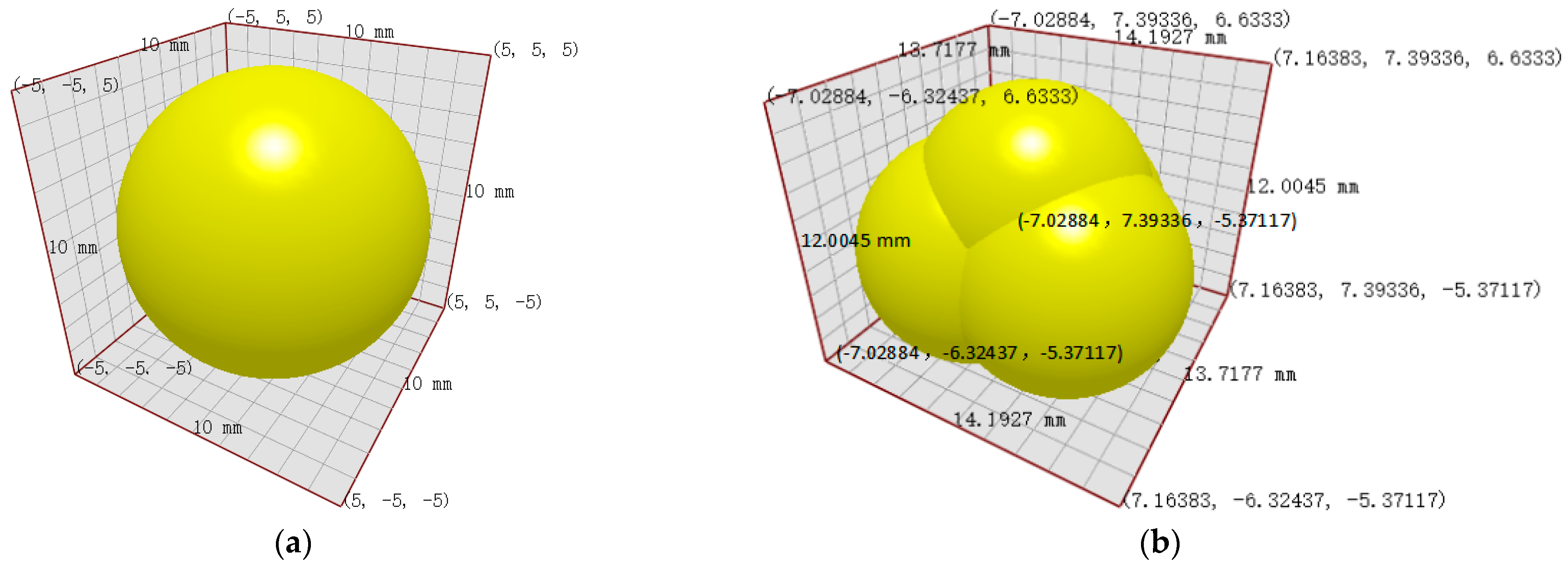
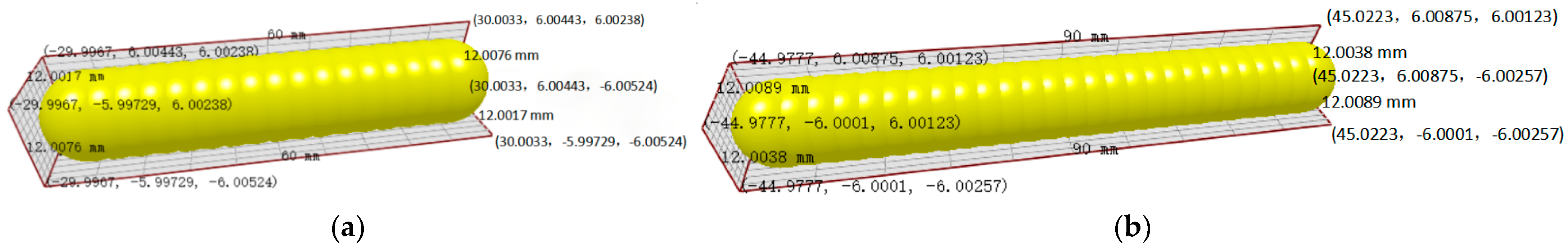
2.4.2. Construction of the Simulation Model

The testing bergamot pear garden is situated in south Xinjiang, which is near the Taklimakan Desert. There are regular-shaped sandy loams in the garden. The soil model was constructed by using particle elements in EDEM. The particle models were set in two types. For the convenience of calculation, it usually set larger soil particles in simulation rather than actual sizes [24]. Therefore, particle size was set as 10mm single spherical particles (Figure 4a) and stacking clusters of 4 particles [25,26] (Figure 4b). Particle number is in normal distribution and particles are connected through Hertz–Mindlin with bonding.
To build a relevant stalk discrete element model [24,25,26,27], a green manure stalk model on the soil surface was constructed. Based on the green manure returning test of the orchard area in summer, the size of the broken green manure stalks was found to be mainly distributed between 50 mm and 100 mm. In this study, 17 particles with a diameter of 6 mm and 27 particles with a diameter of 6 mm formed the approximate cylinder-shaped green manure stalk simulation models consisting of 60 mm and 90 mm in length, respectively (Figure 5). These two models represented the green manure stalks after breaking and pavement.

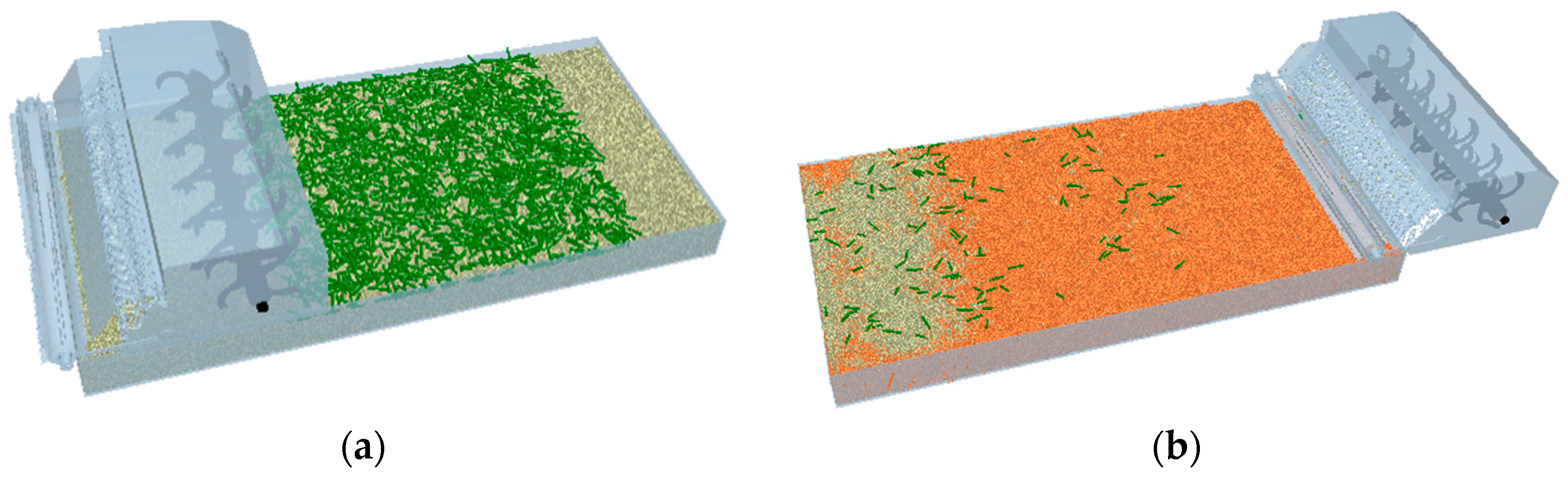
2.4.3. Simulation Test Process

A 3200 mm (Length), 1600 mm (Width) and 300 mm (Height) soil tank model was plotted by Solidworks. The model was assembled with the simplified key components and stored in the format of *.igs. The corresponding data were input into EDEM. Meanwhile, two-particle factories were set to produce the soil model and green manure stalk model. The size of the particle factory which generates soil was consistent with the soil tank model. According to soil density and soil tank area, a total of 1200 kg of soil particles were generated within 0~2 s for the convenience of calculation. After 4s, the soil model and green manure stalk model were completed (Figure 6a). The rotary tillage depth of the whole model was 15 cm. The “stalk pressing plate” of the compacting machine entered into the soil completely. By calculating the transmission ratio, the general advancing speed was fixed at 1.2 m/s, while the axial rotating speed of the rotary tillage cutters was fixed at 600 r/min. Since the compacting machine cannot rotate automatically, its rotating speed was calculated to be 327.27 r/min according to the advancing speed and perimeter of the compacting machine. The operation time of the machine was 4~7 s. For the convenience of calculation, the time step length was fixed at 20% of Rayleigh and the grid unit size was fixed at 5 times the minimum particle radius.

3. Results and Analysis

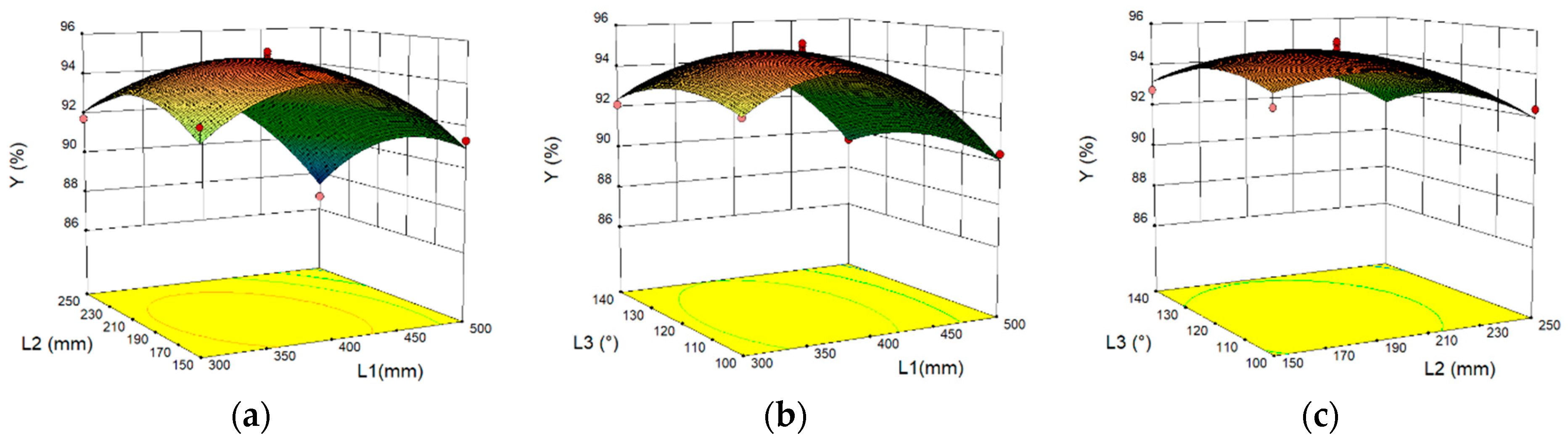
3.1. Discrete Element Simulation Test Results and Optimization

The simulation test scheme and results are shown in Table 3. The burying rate was expressed by Y, which was obtained from the Geometry Bin module in EDEM. Each test was repeated three times while measuring the mean value. As represented in Table 3, the highest burying rate was achieved for the L1 = 400 mm, L2 = 200 mm and θ = 120°. This indicates that the optimal combinations of L1, L2 and L3 were nearly 400 mm, 200 mm and 120°.
To determine the optimal combination parameters of L1, L2 and L3, Box–Behnken analysis was carried out by the Design-Expert-10 software. Regression analysis of the test results was performed. The final regression model of response value Y (Equation (4)) and encoding factors among L1, L2 and L3 were obtained.
Y = 94.87 1.43 L 1 0.88 L 2 0.29 L 3 0.91 L 1 L 2 0.032 L 1 L 3 + 0.043 L 2 L 3 2.84 L 1 2 1.42 L 2 2 0.83 L 3 2
Analysis of variance (ANOVA) was also performed for the model (Table 4). The determination coefficient (R2) was found to be 0.9595, which indicated the high fitting accuracy of the established regression model expression. The fitting missing term of the objective function was 0.0928 > 0.05, which was not significant. In other words, the fitting loss factors did not exist. Moreover, the fitting regression equation could replace real points in the test analysis. The significant P value of the objective function (Y) was determined to be 0.0004, which was smaller than 0.01. This shows that this model is extremely significant and can describe the relationship between the factors and the objective function. From the size of the F value, it can be seen that the linear terms of the model (L1 and L2), as well as the quadratic terms (L12 and L22), were extremely significant, while L32 and the interaction term (L1L2) were significant. The influence of each factor on the index Y is: L1 > L2 > L3. The transverse distance (L1) from the center of the rotary tillage cutter to the root of the “iron chain separation curtain” determines the separation of the thrown green manure stalks from the soil. The width of the transverse plate of the soil retaining board (L2) determines the length of soil movement time after separation and the angle of the soil retaining board (θ)L3 affects soil fall time. In terms of the importance of the three factors, the influence of each factor on the index Y obtained by the variance analysis is reasonable.
The response curve surface of factors to the burying rate is shown in Figure 6. It can be seen in Figure 7a that the fixed factor (L3) is in the intermediate level (120°). When L1 is at a level, the burying rate (Y) presented an inverted V-shaped variation with the increase of L2. When L2 is at a level, Y presented the same variation trend with the increase of L1. Concerning the variation amplitude, L1 influenced Y more than L2. It can be seen from Figure 7b that when L2 = 200 mm and L1 is at a level, Y also presented an inverted V-shaped variation with the increase of L3. When L3 is at a level, Y also presented the same variation trend with the increase of L1. For the variation amplitude, L1 influenced Y significantly compared with L3. It can be seen from Figure 7c that when L1 = 400 mm and L2 is at a level, Y presented an inverted V-shaped variation with the increase of L3. When L3 is at a level, Y also presented the same variation trend with the increase of L2. Concerning the variation amplitude, L2 influenced Y more significantly than L3.
In order to obtain the best matching parameters of the “separation and burying device” of the green manure crushing and rotary tiller integrated machine between the orchard rows, it is necessary to optimize the regression model between the burial rate and various influencing factors and establish a parametric mathematical model. Its nonlinear programming mathematical model is shown in Equation (5).
{ max Y s . t .   300 mm L 1 500 mm     150 mm L 2 250 mm     100 ° L 3 140 °     0 < Y   ( L 1 , L 2 , L 3 ) 1
The model was optimized through the optimization module of Design-Expert-10, resulting in the optimal solution. Under the optimal conditions of L1 = 378.76 mm, L2 = 187.78 mm and θ = 116.48°, the burying rate was found to be the best, while reaching 95.16%.

3.2. Field Test Verification

The green manure shattering-rotary tillage integrated machine in the orchard area is mainly composed of three-point suspension devices, gear case, gear drive systems at two sides, shattering device, rotary tillage device and separated burying device (consisting of “iron chain separation curtain” behind the frame, soil retaining board and earthing roller). The simplified schematic of the whole machine is shown in Figure 8.
During operation, the output power of the tractor’s rear shaft is transmitted to the gear case and its direction is changed by the bevel gear. This output power is transmitted to the gear drive systems at two sides to drive the operation of the shattering device and rotary tillage device. The shattering device cut fresh green manure into pieces. The rotary tillage device mixes the cutting stalks with soils and then buries them together. Meanwhile, green manure that is not cut into satisfactory pieces is cut for the second time. The rotary tillage cutters lift soils and stalks together during rotation. Due to interception by the “iron chain separation curtain”, most stalks fall to the ground, while soils pass through the “iron chain separation curtain” and fall to the ground until they impact onto the soil retaining board, thus covering the green manure stalks. Subsequently, surface green manure stalks are compressed into soils through the zigzag-shaped “stalk pressing plate” on the compacting wheel, which can effectively improve the ploughing effect and increase the burying rate of green manure. The schematic diagram of the green manure returning operation in pear orchard is shown in Figure 9.

3.2.1. Test Conditions

A field test was carried out in the Bergamot Pear Demonstration Base in 12th Group, Alear City, Xinjiang Uygur Autonomous Region (40°28′ N, 81°26′ E) on 23 October 2021. The study area covered 500 mu and the soil type was sandy loam. Before the test, soil moisture content and soil density between rows as well as the moisture content in oilseed rape stalk were measured at 10 random points and mean values were taken. At depths of 5 cm, 10 cm and 15 cm, the soil moisture contents were measured to be 10.35%, 12.76% and 13.12%, respectively. The soil densities were measured to be at 152.5 Kpa, 166.3 Kpa and 182.9 Kpa, respectively, whereas the average moisture content in oilseed rape stalk was at 72.46%.
The test included a Luzhong 604 tractor, ZN-C20002 electronic balance with an accuracy of 0.01g, TYD-2 digital display soil hardness tester, DHS-10A fast moisture testing machine, UT373 digital non-contact tachometer, original geotome, 50 m tape measure, 4.5 m flexible ruler, 30 cm steel ruler, chronometer and shovels.

3.2.2. Test Method

The ordinary rotary tillage machine without a “separated burying device” was used as the control group, while the machine with a “separated burying device” (round-off parameters) was used as the test group. The field verification test was carried out once the operation speed reached 3.6 km/h. The test was conducted according to the national standards of Operation Quality for Stalk Shattering and Returning Machine NY/T500-2015, Operation Quality for Rotary Tillage Machine NY/T499-2013, etc. The field test is shown in Figure 10. The elliptical position in the figure is the non-buried green fertilizer stem.
Five test points were chosen at an equal interval in the operation region of the machine while having 1 m2 scope of each point. Green manure above the surface and 15cm below the surface were screened by a sieve. If the coverage length of green manure crops was shorter than 2/3 of the total length, it was determined as no coverage. Samples were collected in a sealed bag, weighed and recorded. To decrease errors, samples were weighted thrice, and the mean value was considered. With reference to the Operation Quality of Furrow Plow NY/T742-2003, the green manure coverage after operation of the machine was calculated according to Equations (5)–(7), where mX1, mX2 and mX3 were results of three measurements of green manures above the surface at each point; mY1, mY2 and mY3 were results of three measurements of green manures at 15cm below the surface at each point. Test results are presented in Table 5.
Z 1 = m X 1 + m X 2 + m X 3 3
where Z1 is the vegetation and residual mass above the surface (kg).
Z 2 = m Y 1 + m Y 2 + m Y 3 3
where Z1 is the vegetation and residual mass at 15 cm below the surface (kg).
F = Z 2 Z 1 + Z 2 × 100
where F is the green manure coverage below the surface (%).
According to the field test, the “separated burying device” did not block during the whole test process, which shows that the “Chain separation curtain” structural design is reasonable and reliable. Before designing the “separation burial device”, the average burial rate of green manure crops was 89.53% when the turning depth was 150mm. After designing the “separating burying device”, the average burying rate of green manure crops was 94.36% when the turning depth was 150mm, and the green manure burial rate increased 4.84%, verifying the feasibility of the “separated buried device”. Compared with the optimal burial rate of 95.16% in the discrete element simulation test, the error is 0.8%, far less than 5%, which verifies the scientificity, feasibility and accuracy of the quadratic polynomial regression model.

4. Discussion

This paper studies methods for improving the effect of orchard green manure burial and returning to the field. At present, Chinese scholars mainly conduct field experiments by changing the type of green manure returning to the field. To our knowledge, no proprietary burial device has been designed to enhance the effectiveness of green manure. Therefore, the design of a “separating burying device” is innovative and scientific. Yang et al. [16] designed and developed a telescopic finger-type corn stalk rotary tillage burial machine, which uses telescopic fingers and an eccentric shaft to separate the straw from the soil, which can efficiently bury the crushed corn stalks. The similarity to this design is that the rotary tiller group is used for burial, and the method of separation and burial is adopted. The difference is that the buried objects are different, and the methods of separation and burial are different. The specific performance is as follows: in this design, the rotary tiller of the original machinery is directly used for throwing, and the green fertilizer stalk and soil are separated through the free shaking “Chain separation curtain”. This can prevent the clogging of green manure stems, and the effect of separation and burial is better. Due to the difference in burial depth and material properties, the test results are not comparable. It can be seen from the field comparison test that the average burial rate of green manure is 89.53% before the design of the “separating burying device”, and the average burial rate of green manure after the design of the “separating burying device” is 94.36%, an increase of 4.84%.
Through the analysis of the research status of green manure returning machinery at home and abroad, it is found that in southern Xinjiang, China, the use of orchard green manure returning to the field is mainly through theoretical analysis, integrating the advantages of different structures, and carrying out prototype modification optimization and field verification. However, this study innovatively designed a “separating burying device” composed of “Chain separation curtain”, earth retaining plate and suppression device, which improved the burying effect of green manure crops and was beneficial to the decomposition and nutrient release and utilization of green manure crops. It created good conditions for re-seeding and optimized the quality of seed beds. No structural design research related to improving the burial rate of green manure has been found, so the research has a certain novelty.
This study has carried out some innovative structural designs, but there are also some limitations. The specific contents are as follows:
(1)
The designed “separating burying device” needs to be used in conjunction with the rotary tiller, so the “separating burying device” can only be used in conjunction with the machine that uses rotary tillage to bury green manure, and is not suitable for other machines.
(2)
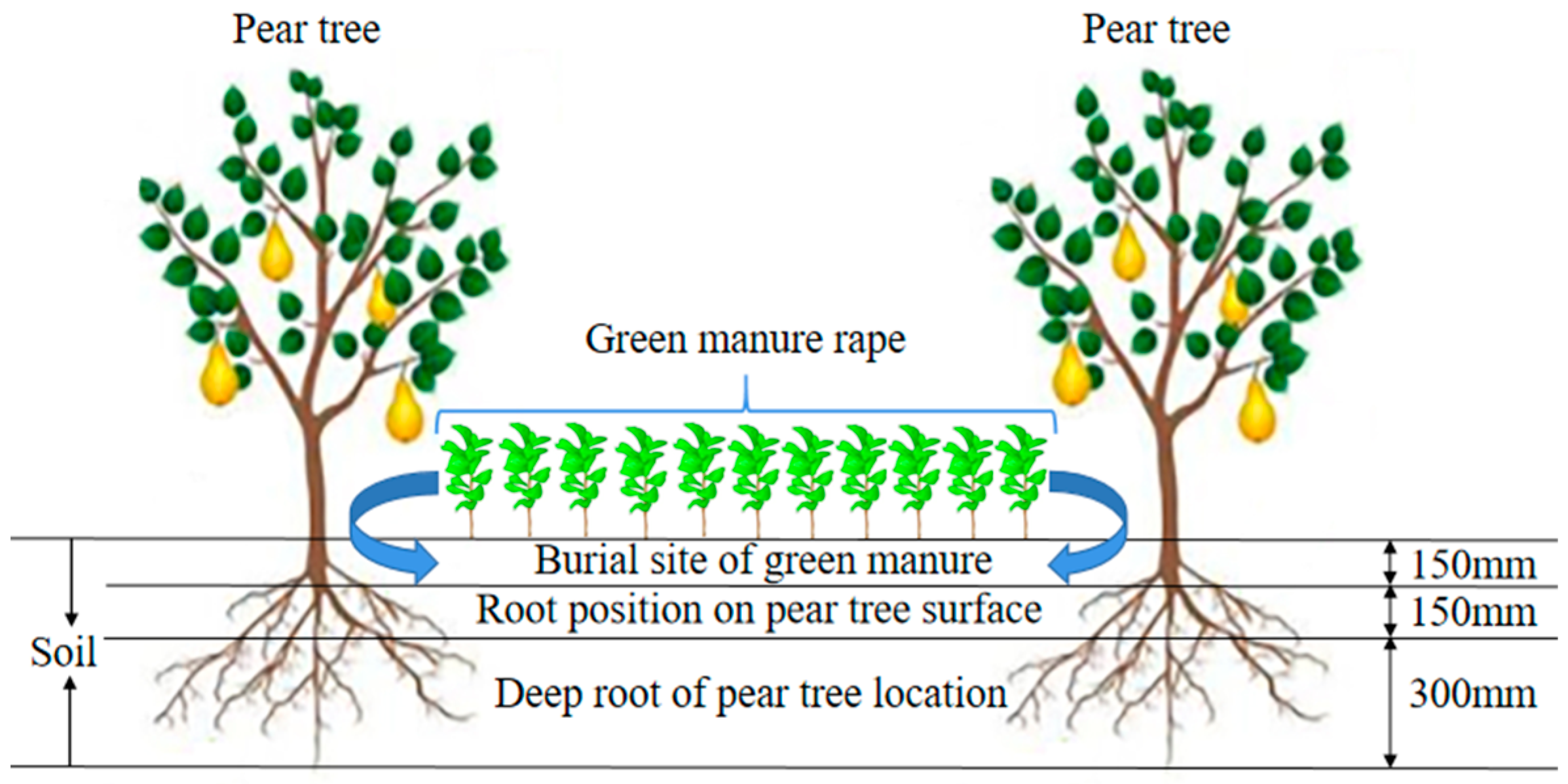
The simulation test and field test in this paper are mainly aimed at the fragrant pear orchard in Alar City, Xinjiang, China. The soil type is sandy loam, and the green manure crop is only rape. The next step will be to study the structural optimization of the “separating burying device” under different soil conditions and different types of green manure, in order to achieve the purpose of reducing drag and consumption, improving performance and versatility.

5. Conclusions

(1)
Completed the overall structural design of the “separated burying device”, which is mainly composed of “Chain separation curtain”, earth retaining plates and suppressors, achieved the goal of “stalk falling first and soil falling later” during green manure returning.
(2)
A cooperative parameter model of the “separated burying device” was constructed through a discrete element model and the feasibility of the model was verified. It can predict the burying rate of green manures. Cooperative parameters of the key components were optimized through regression and response surface analysis. The machine achieved the highest burying rate (95.16%) for L1 = 378.76 mm, L2 = 187.78 mm and θ = 116.48°.
(3)
In order to verify the reliability, scientificity and feasibility of the “separated burying device”, a field test was carried out. Before designing the “separation burial device”, the average burial rate of green manure crops was 89.53% when the turning depth was 150 mm. After designing the “separating burying device”, the average burying rate of green manure crops was 94.36% when the turning depth was 150 mm, and the green manure burial rate increased 4.84%, verifying the feasibility of the “separated buried device”. Compared with the optimal burial rate of 95.16% in the discrete element simulation test, the error is 0.8%, far less than 5%, which verifies the scientificity, feasibility and accuracy of the quadratic polynomial regression model.

Author Contributions

Resources, J.L.; data curation, X.L.; writing—original draft preparation, W.Y. and J.Z.; writing—review and editing, J.Z. and L.X.; visualization, X.L.; supervision, J.L.; project administration, J.L. and L.X. All authors have read and agreed to the published version of the manuscript.

Funding

This is research was financially supported by the China Agriculture Research System of MOF and MARA (CARS-22), Xinjiang Construction Corps, grant number (2021CB022), the Finance science and technology project of Alar City (2021NY07) and the Key neighborhood Science and Technology Project of Xinjiang Construction Corps (2018AB037).

Institutional Review Board Statement

Not applicable.

Informed Consent Statement

Not applicable.

Data Availability Statement

The data presented in this study are available on request from the corresponding author.

Acknowledgments

This work was supported by financial scientific and technological projects of China Agriculture Research System of MOF and MARA (CARS-22), Xinjiang Construction Corps, grant number (2021CB022), the Finance science and technology project of Alar City (2021NY07) and the Key neighborhood Science and Technology Project of Xinjiang Construction Corps (2018AB037). The authors are grateful to the anonymous reviewers for their comments.

Conflicts of Interest

The authors declare no conflict of interest.

References

  1. Guo, R. China Ethnic Statistical Yearbook 2020; Springer: Berlin/Heidelberg, Germany, 2020. [Google Scholar]
  2. Zhao, C.; Gao, B.; Wang, L.; Huang, W.; Xu, S.; Cui, S. Spatial patterns of net greenhouse gas balance and intensity in Chinese orchard system. Sci. Total Environ. 2021, 779, 146250. [Google Scholar] [CrossRef] [PubMed]
  3. Guo, H.; Cao, Y.; Song, W.; Zhang, J.; Wang, C.; Wang, C.; Yang, F.; Zhu, L. Design and Simulation of a Garlic Seed Metering Mechanism. Agriculture 2021, 11, 1239. [Google Scholar] [CrossRef]
  4. Giacalone, G.; Peano, C.; Isocrono, D.; Sottile, F. Are Cover Crops Affecting the Quality and Sustainability of Fruit Production? Agriculture 2021, 11, 1201. [Google Scholar] [CrossRef]
  5. Mamiev, D.; Abaev, A.; Tedeeva, A.; Khokhoeva, N.; Tedeeva, V. Use of Green Manure in Organic Farming. In IOP Conference Series: Earth and Environmental Science; IOP Publishing: Bristol, UK, 2019; Volume 403, p. 012137. [Google Scholar]
  6. Jarvis, N.; Forkman, J.; Koestel, J.; Kätterer, T.; Larsbo, M.; Taylor, A. Long-term effects of grass-clover leys on the structure of a silt loam soil in a cold climate. Agric. Ecosyst. Environ. 2017, 247, 319–328. [Google Scholar] [CrossRef]
  7. Ma, D.; Yin, L.; Ju, W.; Li, X.; Liu, X.; Deng, X.; Wang, S. Meta-analysis of green manure effects on soil properties and crop yield in northern China. Field Crop. Res. 2021, 266, 108146. [Google Scholar] [CrossRef]
  8. Yao, Z.; Xu, Q.; Chen, Y.; Liu, N.; Li, Y.; Zhang, S.; Cao, W.; Zhai, B.; Wang, Z.; Zhang, D.; et al. Leguminous green manure enhances the soil organic nitrogen pool of cropland via disproportionate increase of nitrogen in particulate organic matter fractions. Catena 2021, 207, 105574. [Google Scholar] [CrossRef]
  9. Zhang, L.; Cao, M.; Xing, A.; Sun, Z.; Huang, Y. Modelling the Spatial Expansion of Green Manure Considering Land Productivity and Implementing Strategies. Sustainability 2018, 10, 225. [Google Scholar] [CrossRef] [Green Version]
  10. Breland, T.A. Measured and predicted mineralization of clover green manure at low temperatures at different depths in two soils. Plant Soil 1994, 166, 13–20. [Google Scholar] [CrossRef]
  11. Lu, L.; Wang, W.; Wang, X.; Zhang, L.; Li, A.; Gao, M.; Zhang, L.; Li, B.; Han, M. Release of nutrients during the de-composition of green manure in different levels of the soil in an apple orchard in Weibei highland. J. Fruit Sci. 2018, 35, 586–595. [Google Scholar]
  12. Zekić, V.; Rodić, V.; Jovanović, M. Potentials and economic viability of small grain residue use as a source of energy in Serbia. Biomass- Bioenergy 2010, 34, 1789–1795. [Google Scholar] [CrossRef]
  13. Nørremark, M.; Griepentrog, H.W.; Nielsen, J.; Søgaard, H.T. Evaluation of an autonomous GPS-based system for intra-row weed control by assessing the tilled area. Precis. Agric. 2012, 13, 149–162. [Google Scholar] [CrossRef]
  14. You, Z.; Gao, X.; Wang, G.; Yu, X.; Hu, R. Design and experiment of GFY-200 type crushing and overturning combined machine for economic green manures. J. Chin. Agric. Mech. 2021, 42, 116–121. [Google Scholar] [CrossRef]
  15. Qinglu, Y.; Guibin, C.; Lijuan, X.; Qingjie, W.; Jin, H.; Hongwen, L. Design and Experiment of Telescopic Finger Stalk of Maize Straw Burying Machine. Trans. Chin. Soc. Agric. Mach. 2020, 51, 35–43. [Google Scholar]
  16. Rosa, D.M.; Nóbrega, L.H.P.; de Lima, G.P.; Mauli, M.M. Corn crop sown during summertime under leguminous residues in a no-tillage system. Semin. Ciências Agrárias 2011, 32, 1287–1296. [Google Scholar] [CrossRef] [Green Version]
  17. Brozović, B.; Jug, D.; Đurđević, B.; Vukadinović, V.; Tadić, V.; Stipešević, B. Influence of winter cover crops incorpo-ration on weed infestation in popcorn maize (Zea mays everta Sturt.) organic production. Agric. Conspec. Sci. 2018, 83, 77–81. [Google Scholar]
  18. Xu, L.; Zhao, S.; Ma, S.; Niu, C.; Yan, C.; Lu, C. Optimized design and experiment of the precise obstacle avoidance control system for a grape interplant weeding machine. Trans. Chin. Soc. Agric. Eng. Trans. CSAE 2021, 37, 31–39, (In Chinese with English abstract). [Google Scholar]
  19. Konstantinov, Y.V.; Akimov, A.P.; Medvedev, V.I.; Maksimov, A.N. Calculation of the power requirement for soil cutting by rotary tool blade. In Journal of Physics: Conference Series; IOP Publishing: Bristol, UK, 2020; Volume 1679. [Google Scholar]
  20. Zhao, H.; Huang, Y.; Liu, Z.; Liu, W.; Zheng, Z. Applications of Discrete Element Method in the Research of Agricultural Machinery: A Review. Agriculture 2021, 11, 425. [Google Scholar] [CrossRef]
  21. Liao, Y.T.; Wang, Z.T.; Liao, Q.X.; Wan, X.Y.; Zhou, Y.; Liang, F. Calibration of Discrete Element Model Parameters of Forage Rape Stalk at Early Pod Stage. Trans. Chin. Soc. Agric. Mach. 2020, 51, 236–243. [Google Scholar]
  22. Jianping, H.; Jun, Z.; Haoran, P.; Wei, L.; Xingsheng, Z. Prediction Model of Double Axis Rotary Power Consumption Based on Discrete Element Method. Trans. Chin. Soc. Agric. Mach. 2020, 51, 9–16. [Google Scholar]
  23. Maohua, X.; Kaixin, W.; Wang, Y.; Weichen, W.; Feng, J. Design and Experiment of Bionic Rotary Blade Based on Claw Toe of Gryllotalpa orientalis Burmeister. Trans. Chin. Soc. Agric. Mach. 2021, 52, 55–63. [Google Scholar]
  24. Yu, C.; Zhu, D.; Gao, Y.; Xue, K.; Zhang, S.; Liao, J.; Liu, J. Optimization and experiment of counter-rotating straw returning cultivator based on discrete element method. J. Adv. Mech. Des. Syst. Manuf. 2020, 14, JAMDSM0097. [Google Scholar] [CrossRef]
  25. Zhou, H.; Zhang, C.; Zhang, W.; Yang, Q.; Li, D.; Liu, Z.; Xia, J. Evaluation of straw spatial distribution after straw incorporation into soil for different tillage tools. Soil Tillage Res. 2020, 196, 104440. [Google Scholar] [CrossRef]
  26. Zeng, Z.; Chen, Y. Simulation of straw movement by discrete element modelling of straw-sweep-soil interaction. Biosyst. Eng. 2019, 180, 25–35. [Google Scholar] [CrossRef]
  27. Yu, C.; Liu, J.; Zhang, J.; Xue, K.; Zhang, S.; Liao, J.; Tai, Q.; Zhu, D. Design and optimization and experimental verification of a segmented double-helix blade roller for straw returning cultivators. J. Chin. Inst. Eng. 2021, 44, 379–387. [Google Scholar] [CrossRef]
Figure 1. Separated burying device. 1. Rotary tillage blade 2. Rotary blade holder 3. Rotary blade axis 4. Stem model 5. The chain 6. Soil particle model 7. Soil retaining plate 8. To suppress wheel 9. Soil model. (a) Schematic diagram of separation and burial device. (b) Schematic diagram of principle of “separation and burial Device”.
Agriculture 12 00569 g001
Figure 2. “Chain separation curtain” and soil retaining board. (a) Schematic diagram of “Chain separation curtain”. (b) Schematic diagram of soil retaining board.
Agriculture 12 00569 g002
Figure 3. Soil lifting trajectory analysis of rotary tillage cutter.
Agriculture 12 00569 g003
Figure 4. Soil particle model. (a) Single spherical particles. (b) Lumpy particles.
Agriculture 12 00569 g004
Figure 5. Particle models of green manure stalks. (a) 60mm stem model. (b) 90mm stem model.
Agriculture 12 00569 g005
Figure 6. Simulation process of the key components. (a) Soil—stem—“separation and burial device” model. (b) Simulation process.
Agriculture 12 00569 g006
Figure 7. Index response surface analysis of test factors. (a) Y (L1, L2, 120), (b) Y (L1, 200, L3), (c) Y (400, L2, L3).
Agriculture 12 00569 g007
Figure 8. Simplified schematic of green manure shattering-rotary tillage integrated machine between rows in the orchard area. 1. Grass cutter blade; 2. Grass cutter holder; 3. Left side baffle; 4. Gearbox; 5. Left side bezel; 6. Rotary blade; 7. Bearing end cover; 8. Locating hole; 9. Positioning holes; 10. Connection plate of suppression wheel; 11. Suppress wheel; 12. Chain separation curtain positioning rod; 13. Soil retaining plate; 14. The chain; 15. Chain fastening rings; 16. Retaining board positioning pin; 17. The baffle; 18. Left drive shaft; 19. Transmission cover; 20. The transmission; 21. Right drive shaft; 22. Right side baffle plate; 23. Suspension.
Agriculture 12 00569 g008
Figure 9. Green manure returning diagram in the pear garden.
Agriculture 12 00569 g009
Figure 10. Field test. (a) Control group field trial; (b) “separated burying device” Group Field Test.
Agriculture 12 00569 g010
Table 1. Factor level coding table.
Code ValueThe Test Factors
L1 (mm)L2 (mm)L3 (°)
1500250140
0400200120
−1300150100
Table 2. Material parameters.
ProjectParameterProjectParameter
Soil bin (long × wide × high) (mm × mm × mm)3200 × 1600 × 300The soil density (kg/m3)1250
Machine forward speed (m/s)1.2Soil Poisson’s ratio0.4
Speed of rotation of rotary blade ω (rad/s)13.3Soil shear modulus (pa)1 × 10⁶
The density of 65 Mn steel (kg/m3)7860Soil-soil recovery coefficient0.2
Poisson’s ratio of 65 Mn steel0.3Soil-steel recovery coefficient0.6
65 Mn steel shear modulus (pa)7.9 × 10¹⁰Recovery coefficient of stem-steel collision in rape0.6
Canola stem density (kg/m3)809Soil-soil static friction factor0.4
Poisson’s ratio of canola stem0.23Soil-steel static friction coefficient0.6
Rape stem shear modulus (pa)4.704 × 10⁷Stem-steel static friction coefficient of rape0.23
Recovery coefficient of rapeseed stalk collision0.6Soil-soil rolling friction factor0.3
Static friction coefficient between stems in rape0.36Soil-steel rolling friction coefficient0.05
Rolling friction coefficient between stems in rape0.03Rape stem-steel rolling friction factor0.1
Table 3. Simulation test scheme and results.
Test Serial NumberL1 (mm)L2 (mm)L3 (°)Indicators
Y1 (%)
1−1−1092.7
21−1091.31
3−11091.72
411086.7
5−10−192.83
610−190.36
7−10192.1
810189.5
90−1−193.2
1001−192.39
110−1192.76
1201192.12
1300094.76
1400095.18
1500094.92
1600095.3
1700094.2
Table 4. Variance of regression model.
SourceSum of SquaresDegrees of FreedomMean Square ErrorThe F ValueThe p Value
model75.9298.4418.410.0004
L116.47116.4735.940.0005
L26.216.213.520.0079
L30.6610.661.440.2687
L1L23.2913.297.190.0315
L1L30.00422510.0042250.0092190.9262
L2L30.00722510.0072250.0160.9036
L1234.01134.0174.22<0.0001
L228.5218.5218.580.0035
L322.9212.926.360.0397
residual3.2170.46
Loss of quasi item2.4630.824.410.0928
Pure error0.7440.19
aggregate79.1316
Table 5. Green manure coverage.
Test WayMeasuring PointQuality of Green Manure above the Surface Z1 (g)Quality of Green Manure 15 cm below the Surface Z2 (g)Buried Rate F (%)
The control group1125.461090.1589.68
2140.171275.0990.09
3123.84968.2788.66
4169.311256.4188.12
5115.251176.6991.08
Experimental group162.381205.1795.08
282.151138.3293.27
375.461155.6393.87
454.71926.1594.42
563.921259.7495.17
Publisher’s Note: MDPI stays neutral with regard to jurisdictional claims in published maps and institutional affiliations.

