Article

Analysis of the Influence of the Channel Layout and Size on the Hydraulic Performance of Emitters

College of Water Resources Science and Engineering, Taiyuan University of Technology, Taiyuan 030024, China
*
Author to whom correspondence should be addressed.
Agriculture 2022, 12(4), 541; https://doi.org/10.3390/agriculture12040541
Submission received: 17 March 2022 / Revised: 8 April 2022 / Accepted: 8 April 2022 / Published: 11 April 2022
(This article belongs to the Special Issue Water-Saving Irrigation Technology and Strategies for Crop Production)

Abstract

:
In this paper, a split-flow channel layout with one (group) inlet and two (group) outlets is adopted, based on computational fluid dynamics technology, and compared with the current commonly used channel with one (group) inlet and one (group) outlet emitter. On the premise of the same outlet spacing, the pressure–flow relationship curve and slope of the split-flow emitter were analyzed under the three channel layouts of non-return, single-sided re-entry, and bilateral re-entry, with different channel widths and lengths. When exploring the influence of the channel layout and size on the hydraulic performance of split-flow emitters, the results showed that when the split-flow emitter with a non-return channel is adopted and the hydraulic performance is not reduced, the single-side channel length is half that of the one-in-one-out emitter, meaning the channel width needs to be reduced by 15%. When the channel layout is a single-sided channel re-entry, the hydraulic performance is better than that of the one-in-one-out emitter; if the hydraulic performance of the two remains unchanged, the channel width can be increased by 10% or the single-sided channel length can be reduced by 20%. When the channel layout is a bilateral channel re-entry, the channel width can be increased by nearly 30% if the hydraulic performance of the 2 is consistent, and the single-side channel length is increased by about 50%. When the split-flow emitter adopts a non-return channel layout, the channel width needs to be reduced to ensure the hydraulic performance is consistent. If the layout of single-sided channel re-entry or bilateral channel re-entry is adopted, the hydraulic performance is better than that of the one-in-one-out emitter and the hydraulic performance of the two is consistent. Thus, the channel length can be reduced or the channel width increased, which is beneficial for improving the anti-clogging performance of the emitter.

1. Introduction

Drip irrigation technology is a high-efficiency water-saving irrigation technology in the current agricultural irrigation field. With the development of smart agriculture, the drip irrigation system has gradually transformed from a single irrigation function to multi-functional, such as for irrigation, fertilization, gas supplementation, and pesticide application [1,2]. The emitter is the core technology and key piece of equipment in a drip irrigation system [3]; its channel can effectively eliminate excess energy at the inlet, reduce the flow deviation rate of the emitter in the entire pipe network, and ensure a uniform outflow [4]. The structure of the channel of the emitter directly affects the irrigation quality and steady flow performance of the drip irrigation system [5,6], which, in turn, affect the promotion and application of drip irrigation technology [7].
The sensitivity of the outlet flow of the emitter to its working pressure is represented by the hydraulic performance [8], which is usually expressed by the pressure–flow relationship as:
q = k · h x
where k is the flow coefficient, x is the flow state index, q is the flow rate of the emitter (L/h), and h is the inlet pressure of the emitter (m H2O). The hydraulic performance of the emitter, that is, the sensitivity of the flow to the working pressure, can be expressed by the slope of the pressure–flow relationship curve.
Drip irrigation emitters have two important indicators: their hydraulic and anti-clogging performance [9]. Current research studies on the two are largely independent as hydraulic performance and its influencing factors are studied under clear water conditions [10] while the factors causing the emitter to clog and the mechanism of clogging are studied under muddy water conditions [11,12,13]. Changes to the channel structure of the emitter and the selection of parameters, such as the channel width, length, tooth tip stagger, etc., directly affect its hydraulic performance. Li et al. [14] established a fractal flow path with the help of fractal theory. The results showed that the fractal flow path is more complex than a conventional labyrinth channel, and the internal water flow is more turbulent, realizing the full turbulent flow design. Meanwhile, Tian et al. [15] established a two-way mixed-flow emitter and found that, influenced by the water separation and retaining pieces, the water flow entering the channel formed took on various modes of movement, such as flow separation, hedging, and mixing, through which an obvious energy dissipation effect was observed. Wang et al. [16] added internal teeth to the channel of a rectangular labyrinth emitter, and found that by changing the channel structure, the number and intensity of vortices in the channel were changed, thereby affecting the hydraulic performance of the emitter. Further to this, Guo [17] established a two-way countercurrent emitter. The water flow in the channel was fully mixed and had a good energy dissipation effect. Elsewhere, Pan [18] researched a tooth-shaped labyrinth channel emitter and showed that the biggest factor affecting the flow was the cross-sectional area of the water, followed by the total length of the labyrinth channel, width-depth ratio of the channel structure, and curvature of the water flow inside the structure.
Existing research shows [19,20,21] that the sensitive size range of the channel blocked by the emitter is 0.7–1.5 mm, where less than 0.7 mm is very sensitive and greater than 1.5 mm is not sensitive. The size of the channel of most emitters is 0.5–1.2 mm; at such a size, even if the water quality is good and there are complete sedimentation and filtration measures, some fine particles of sediment still enter the channel of the emitter, and sedimentation and consolidation in the channel will cause the emitter to block [22,23,24,25]. Wang [26] pointed out that to improve the anti-clogging performance of the emitter, the channel structure of the emitter can be changed, such as by reducing the length of the channel or increasing the flow cross-section. Ma et al. [27] proposed a barbed labyrinth channel and adopted a constrained optimization design method to carry out multi-objective optimization of the channel of the emitter. Ma et al. [28] then also proposed a variable-curvature labyrinth channel emitter, which adopted a curved wall design to improve the anti-clogging performance of the emitter. Based on the original channel structure, Wei et al. [29] proposed a main-route anti-clogging design method. This method eliminated the flow stagnation zone in the optimized channel and improved the anti-clogging performance of the labyrinth emitter. However, it is not easy to control efforts to improve the anti-clogging performance of the emitter without reducing its hydraulic performance. The above scholars mainly changed the internal structure of the channel, and no research has reported on the influence of the channel layout on the hydraulic performance of the emitter.
Based on the above problems, this paper intended to change the channel of the emitter from the one (group) inlet and one (group) outlet (hereinafter referred to as one-in-one-out) commonly used at present to one (group) inlet and two (group) outlets (hereinafter referred to as split-flow) instead, under the principle of ensuring the same distance between the outlets of each emitter. The goal of this study was to improve the hydraulic performance of the emitter by changing the layout of the channel, and explore whether it is possible to increase the cross-sectional area of the channel or shorten the length of the channel without reducing the hydraulic performance of the emitter, to provide a reference basis for the further development of high-performance emitters.

2. Materials and Methods

2.1. Emitter Layout and Size Parameters

In this paper, when we refer to the size of the labyrinth emitter used in the side-type drip irrigation belt of Xinjiang Tianye Group, the channel depth of the one-in-one-out emitter (No. Z) and split-flow emitter (Nos. A, B, C and D) is 1 mm, and the space between the outlets of each emitter is 300 mm (or close to 300 mm, to ensure the integrity of the channel unit). The former has a channel width of 1 mm and a channel horizontal length of 300 mm. The latter takes different channel widths and lengths according to different channel layouts: non-return (Type A), single-sided re-entry (Types B and C), and bilateral re-entry (Type D). A schematic diagram of the channels of various types of emitters is shown in Figure 1, and the parameters of the one-in-one-out emitter are given in Table 1.

2.2. Governing Equations and Boundary Conditions

In this study, the FLUENT software [30,31] based on computational fluid dynamics was used to numerically simulate the water flow in the aforementioned various types of emitters, and the pressure–flow relationship curve of the emitter was obtained. The advantages and disadvantages of the hydraulic performance of the emitter were then further analyzed. The movement of water flow inside the emitter can be regarded as the movement of viscous incompressible fluid. This paper mainly studied the hydraulic performance of the emitter at room temperature; regardless of the temperature field change caused by the energy exchange of water flow, the motion law conforms to the conservation of mass and momentum, and does not consider the mass force, so the governing equations include the continuity equation and Navier–Stokes.

2.2.1. Governing Equations

Continuity equation:
u i x i = 0
Navier–Stokes equation:
u i t + x j ( u i u j ) = 1 ρ p x i + v 2 u i x j x j
where t is time, s; ρ is the density of water, kg/m3; ν is the kinematic viscosity, m2/s; p is the fluid pressure, Pa; u i , u j is the flow velocity tensor; and x i , x j is the coordinate tensor.
The existing research indicates that selection of the standard k-ε turbulence model (a semi-empirical turbulence model) for the simulation calculation of the labyrinth channel emitter in this paper would be most consistent with the actual situation [32]. When the fluid is incompressible and user-defined source terms are not considered, the basic transport equations for solving the turbulent kinetic energy k and dissipation rate ε are:
k equation:
( ρ k ) t + ( ρ k u i   ) ( x i ) = ( x j )   [ ( μ + μ t σ k ) k ( x j ) ] + G k ρ ε
ε equation:
( ρ ε ) t + ( ρ ε u i   ) ( x i   ) = ( x j   )   [ ( μ + μ t σ ε ) ε ( x j ) ] + ( C 1 ε   ε ) k G k C 2 ε ε 2 k
Among them:
G k = μ t ( u i x j + u j x i ) u i x j
μ t = ρ C μ k 2 ε
where k is turbulent energy, J; ε is the turbulent dissipation rate; μ t is turbulent viscosity Pa·s; t is time, s; μ is viscosity N·s/m2; x i , x j is the coordinate tensor; and G k is the production term of the turbulent energy k caused by the average velocity gradient. The empirical constants are C 1 ε = 1.44, C 2 ε = 1.92, C μ = 0.09 , σ k = 1.0, and σ ε = 1.3.

2.2.2. Mesh and Boundary Conditions

We used a structured hexahedral mesh [33]. To reduce the influence of the mesh on the flow calculation results, with mesh sizes of 0.1, 0.09, 0.08, 0.07, 0.06, 0.05, and 0.04 mm, the flow of the emitter was calculated for each when the inlet pressure was 5, 10, or 15 m H2O. Considering instances when the mesh size was 0.04 or 0.05 mm, the difference in the flow of the emitter between the two mesh sizes was 0.29%, which is less than 0.5% [34]. We considered this did not affect the calculation results, and the mesh size was this set to 0.05 mm in this research. When the boundary layer parameters were selected, the thickness of the first boundary layer was taken as 0.01 mm, and for each layer, it was increased by 1.5 times; hence, with 6 layers, the total thickness of the boundary layer was 0.208 mm.
The calculations were performed using an uncoupled implicit steady-state solver, and the inlet and outlet turbulence parameters were defined by the hydraulic diameter and turbulence intensity, with the latter being 5%. The inlet boundary conditions were set to a 5–15 m H2O pressure inlet, and the outlet boundary was set to the atmospheric pressure. The wall was a non-slip boundary. For the flow in the wall area, the standard wall function [35] was used, and the wall roughness was 0.01 mm. The numerical calculation used the finite volume method to discretize the governing equations. The convection term and other parameters were discretized using the second-order upwind style, and the coupling of velocity and pressure was solved by the SIMPLE algorithm, with a convergence accuracy of 10−4.

3. Results and Discussion

3.1. Calculation Results and Physical Model Test Verification

To ensure the correctness of the calculation results, the physical model of the one-in-one-out channel emitter was verified in our work. The channel of the model emitter was 1.2 mm wide, 1.8 mm deep, and 301.2 mm long. The model is pictured in Figure 2.
The test system mainly included a water tank, pump, water supply and return pipelines, test model, and precision pressure gauge. A schematic diagram is shown in Figure 3.
The physical quantities tested in the experiment were the inlet pressure and outlet flow of the emitter. The inlet pressure was measured by a 0.25-grade pressure gauge with a maximum range of 0.16 MPa and an accuracy of 0.0005 MPa, and the flow was measured with 200 and 500 mL measured cylinders according to the outflow. The test was in accordance with the test specification of Micro-Emitter Irrigator-Dripper (SL/T67.1-94). The flow was measured twice under each inlet pressure, the time taken for each flow measurement was no less than 2 min, the difference between the two measured flows was no more than 2%, and the average value of 2 times was taken as the discharge flow (L/h) of the emitter.
The results of our numerical simulation and model test are shown in Table 2 and Figure 4. It can be seen from Table 2 that the maximum error between them is 2.4%, which verifies the correctness of our selection of mesh, in terms of its size and the calculation method.

3.2. Computational Results and Analysis

By fitting the simulation results for Type Z and Types A, B, C, and D split-flow emitters in the pressure range of 5–15 m H2O, their pressure–flow relationship curves, flow coefficient k, and flow state index x could be obtained. The slope of the pressure–flow relationship curve for each emitter at different working pressures was calculated according to:
q = k · x · h ( x 1 )
where k is the flow coefficient; x is the flow state index; q is the flow rate of the emitter, L/h; and h is the inlet pressure of the emitter, m H2O. The advantages and disadvantages of the hydraulic performance of the one-in-one-out and split-flow emitters were compared and analyzed in terms of the outlet flow (design flow) at the inlet pressure of 10 m H2O and the slope of the pressure–flow relationship curve.

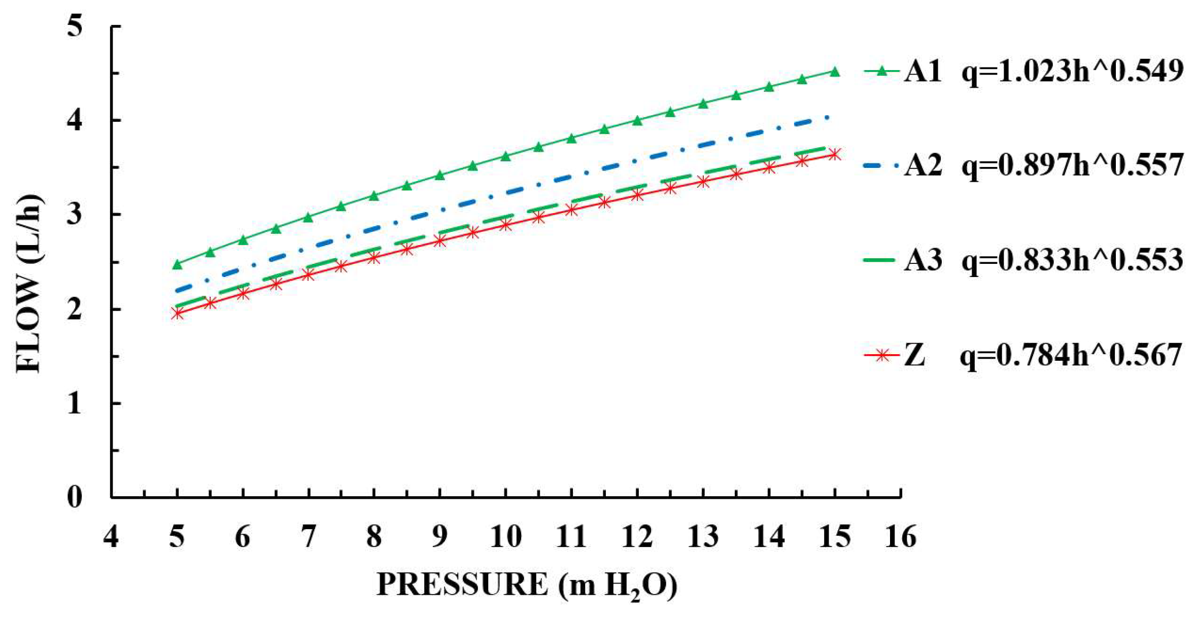
3.2.1. Hydraulic Performance of the Type A Emitter

The Type A emitter simply changed one inlet and one outlet to one inlet and two outlets. Parameters, such as the single-sided channel length (L2), total number of units, and outlet spacing of the emitters with different channel widths are shown in Table 3; Figure 5 shows the pressure–flow relationship curve; and the slope of the pressure–flow relationship curve, along with a comparison of parameters under different working pressures, is shown in Table 4.
Results can be seen in Table 3 and Table 4 for the split-flow emitter with a non-return channel, on the premise that the one-sided channel length (L2) is half that of the channel length of the one-in-one-out emitter (L2 = L1/2). The channel width is equal to the channel width of the one-in-one-out emitter, or the former is 90% of the latter, meaning the slope of the pressure–flow relationship curve and the design flow both increase (A1 and A2 emitters). The maximum increase in the slope of the curve is 22.73%, and the design flow increases by 25.19%. If the outlet spacing of the 2 is kept constant (or close) under this condition, the slope of the curve and design flow are consistent or close, meaning the channel width of the Type A emitter needs to be reduced to 0.85 mm, 15% less than that of the Type Z emitter. This shows that when the channel layout of the emitter is changed from 1 outlet to 2, if the hydraulic performance remains unchanged, the channel width needs to be reduced by about 15% when the single-sided channel length is reduced by nearly 50%, and the reduction of the channel width will be detrimental to the anti-clogging performance of the emitter [36] (the effect of reducing the channel length on the anti-clogging performance of the emitter was not considered).

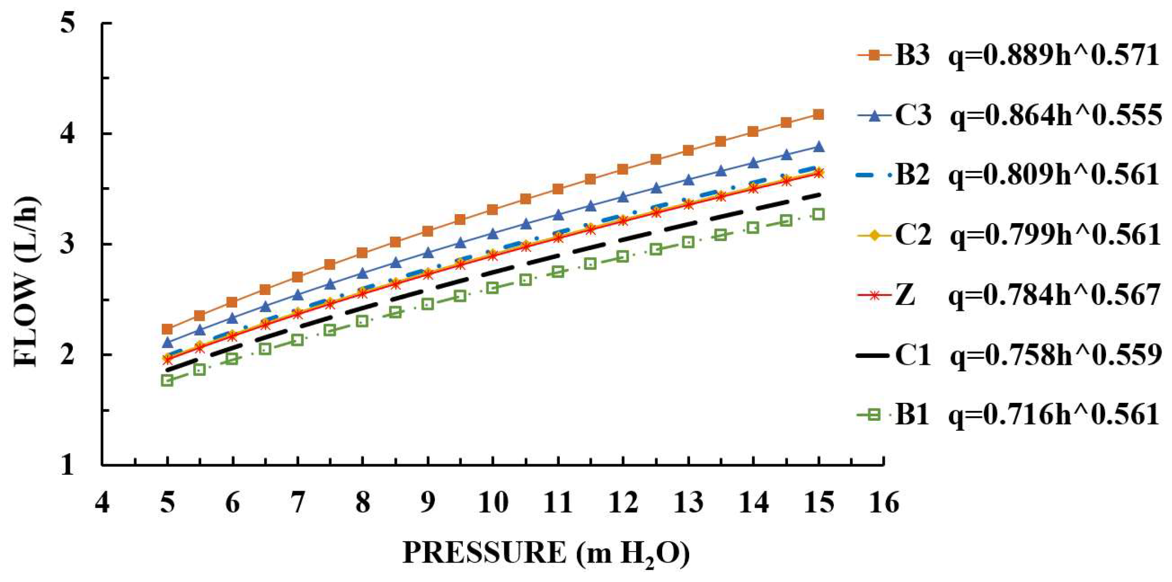
3.2.2. Hydraulic Performance of Type B and Type C Emitters

In view of the problems with the Type A emitter, we lengthened the single-sided channel length of the split-flow emitter to be the same as that of the Type Z emitter, to form a Type B emitter. The single-sided channel length of the Type B emitter was L1 or 2L3 (L1 = 2L3). Then, we lengthened the emitter to be longer than the Type A emitter but shorter than the Type Z emitter to form a Type C emitter. The single-sided channel length of the Type C emitter was L6, i.e., L4 + L5 (L6 = L4 + L5 < L1). We ensured that the outlet spacing was the same as that of the Type Z emitter, with single-sided channel re-entry. The total number of units, channel width, outlet spacing, and other parameters are shown in Table 5. The pressure–flow relationship curve in the inlet pressure range of 5–15 m H2O is shown in Figure 6. The curve slope and its parameter comparison with the Type Z emitter are shown in Table 6.
It can be seen from Table 5 and Table 6 that if the channel of the split-flow emitter adopts single-sided channel re-entry, when the outlet spacing, channel width and single-sided channel length are all consistent with those of the Type Z emitter, the slope of the curve and design flow of the former are less than those of the latter. The slope is reduced by 11.10% at the maximum, and the design flow is reduced by 9.93% (B1 emitter). This shows that changing the channel layout from one-in-one-out to split-flow(one-in-two-out) is beneficial for improving the hydraulic performance of the emitter.
On the other hand, we can increase the channel width or reduce the channel length of the emitter without improving the hydraulic performance of the B1 emitter, that is, to ensure that the hydraulic performance of the B1 and Z emitters is consistent or largely the same. When the outlet spacing of the 2 types of emitters and single-sided channel length is the same, the channel width can be increased by 10% (B2 emitter). When the channel width is increased by 20%, its hydraulic performance will be greatly reduced (B3 emitter). When the outlet spacing of the 2 types of emitters and the channel width are the same, the maximum channel length (L6) can be reduced from 300 to 240 mm, a reduction of 20% (C2 emitter). When the channel length (L6) is reduced from 300 to 270 mm (10% reduction), the design flow is 5.08% lower than that of the Type Z emitter, and the slope of the pressure–flow relationship curve is reduced by 6.72% (C1 emitter). When the channel length (L6) is reduced from 300 to 210 mm by 30%, the slope of the pressure–flow relationship curve and the design flow both increase (by 7.2% and 5.81%, respectively), and the hydraulic performance decreases (C3 emitter).

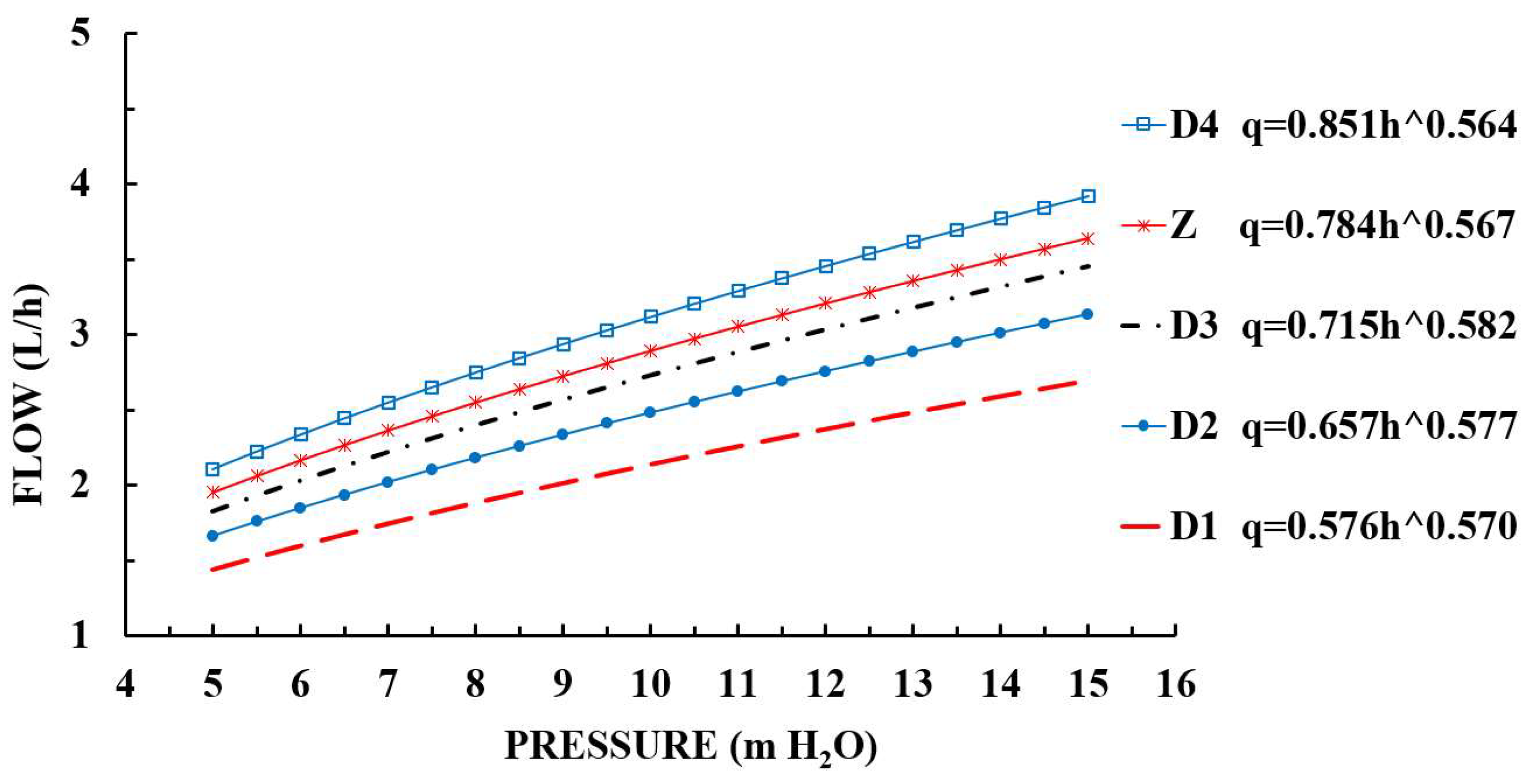
3.2.3. Hydraulic Performance of the Type D Emitter

To further improve its anti-clogging performance, on the premise that the hydraulic performance of the split-flow emitter and one-in-one-outlet emitter, along with the outlet spacing, remained unchanged, we adopted a bilateral channel re-entry layout. In doing so, we were trying to increase the channel width by increasing the channel length of the split-flow emitter, thus forming the Type D emitter. The single-sided channel length of the Type D emitter was L1/2 + 2L7. For parameters, such as the total number of units of the emitter, single-sided channel length, and outlet spacing for different channel widths, see Table 7. The pressure–flow relationship curve within the inlet pressure range of 5–15 m H2O is shown in Figure 7, and Table 8 shows the slope of the curve and compares it with the parameters of the Type Z emitter.
It can be seen from Table 7 and Table 8 that when the split-flow emitter adopts bilateral channel re-entry, and the single-sided channel length is increased by about 50% compared with the channel length of the one-in-one-out emitter, if the width of the 2 channels is the same, the design flow of the former is reduced by 26.02%, and the maximum slope of the pressure–flow relationship curve is reduced by 25.78% (D1 emitter). If the former channel width is increased by 10 or 20%, the designed flow is reduced by 14.25 or 5.6%, respectively, and the maximum slope of the pressure–flow relationship curve is reduced by 13.34 or 4.1% (D2 and D3 emitters), indicating that the hydraulic performance is still better than that of the one-in-one-out emitter. When the channel width of the split-flow emitter increases by 30%, the design flow and maximum slope of the pressure–flow relationship curve increase by 7.8 and 7.45%, respectively, with an increase of less than 10% (D4 emitter). This shows that the split-flow emitter with bilateral channel re-entry can increase the channel width by nearly 30% if the single-sided channel length increases by nearly 50%, under the condition that the hydraulic performance and outlet spacing are the same as those of the one-in-one-out emitter.

4. Conclusions

By analyzing these simulation results for a split-flow emitter (Types A, B, C, and D) and one-in-one-out emitter (Type Z), the following conclusions can be drawn:
  • When the channel of the split-flow emitter is non-return (Type A), it is essential to ensure that its hydraulic performance and the spacing of each outlet are consistent with those of the one-in-one-out emitter. The single-sided channel length must be half that of the channel length of the one-in-one-out emitter, and the channel width needs to be reduced by 15%.
  • When the channel of the split-flow emitter has single-sided re-entry (Types A and B), the hydraulic performance of the former is better than that of the latter when the spacing of each outlet is the same as that of the one-in-one-out emitter. If the hydraulic performance of the 2 is the same, the channel width can be increased by 10% or the single-sided flow channel length can be reduced by 20%. In doing so, the anti-clogging performance of the emitter can be improved on the premise that the hydraulic performance is not reduced.
  • When the channel of the split-flow emitter has bilateral re-entry (Type D), the channel width can be increased by nearly 30% under the condition of ensuring that its hydraulic performance and the spacing of each outlet are consistent with those of a one-in-one-out emitter, and the single-sided channel length is increased by about 50%. This will also help to improve the anti-clogging performance of the emitter.
  • When a split-flow emitter adopts a non-return channel layout, the channel width needs to be reduced to ensure the hydraulic performance is consistent. If a single-sided or bilateral channel re-entry layout is adopted, and its hydraulic performance is better than that of the one-in-one-out emitter, or if the hydraulic performance of the two is consistent, the channel length can be reduced or the width increased, which is beneficial to improving the anti-clogging performance of the emitter.

5. Patents

The contents of this research have been patented by our team, and the patent information is as follows: Zhiqin, L.; Peisen, D.; Cuncai, W. A Labyrinth Drip Emitter. Chinese patent CN215269878U; Taiyuan, China, 2021.

Author Contributions

P.D. edited the original draft; Z.L. reviewed and edited the draft; C.W. provided software guidance; J.M. obtained the funding. All authors have read and agreed to the published version of the manuscript.

Funding

This work was supported by the National Natural Science Foundation of China (52079085).

Institutional Review Board Statement

Not applicable.

Data Availability Statement

The data that support the findings of this study are available from the corresponding author on reasonable request.

Acknowledgments

The authors thank the College of Water Resources Science and Engineering for providing the site for the experiment and data collection.

Conflicts of Interest

The authors declare no conflict of interest.

References

  1. Luo, L.; Wang, H.; Zhang, X.; Zhang, Q.; Li, B. Effect of fertilizer type and concentration on hydraulic performance of drip-fertigation system. Water Sav. Irrig. 2021, 57–60, (In Chinese with English Abstract). Available online: https://jglobal.jst.go.jp/en/detail?JGLOBAL_ID=202202241409730553 (accessed on 7 April 2022).
  2. Li, Y.; Zhou, B.; Yang, P. Research advances in drip irrigation emitter clogging mechanism and controlling methods. J. Hydrol. Eng. 2018, 49, 103–114, (In Chinese with English Abstract). [Google Scholar]
  3. Madramootoo, C.; Morrison, A. Advances and challenges with micro-irrigation. Irrig. Drain. 2013, 62, 255–261. [Google Scholar] [CrossRef]
  4. Gil, M.; Rodríguez-Sinobas, L.; Juana, L.; Sánchez., R.; Losada, A. Emitter discharge variability of subsurface drip irrigation in uniform soils: Effect on water-application uniformity. Irrig. Sci. 2008, 26, 451–458. [Google Scholar] [CrossRef] [Green Version]
  5. Han, D.; Zhou, T. Soil water movement in the unsaturated zone of an inland arid region: Mulched drip irrigation experiment. J. Hydrol. 2018, 559, 13–29. [Google Scholar] [CrossRef]
  6. Mangrio, A.G.; Asif, M.; Ahmed, E.; Sabir, M.W.; Khan, T.; Jahangir, I. Hydraulic performance evaluation of pressure compensating (pc) emitters and micro-tubing for drip irrigation system. Sci. Technol. Dev. 2013, 32, 290–298. [Google Scholar]
  7. Li, Y.; Feng, J.; Song, P.; Zhou, B.; Wang, T.; Xue, S. Developing situation and system construction of low-carbon environment friendly drip irrigation technology. Trans. CSAM 2016, 47, 83–92, (In Chinese with English Abstract). [Google Scholar]
  8. Zhang, L.; Merkley, G.P. Relationships between common irrigation application uniformity indicators. Irrig. Sci. 2012, 30, 83–88. [Google Scholar] [CrossRef]
  9. Reinders, F.B.; Niekerk, A. Technology smart approach to keep drip irrigation systems functional. Irrig. Drain. 2018, 67, 82–88. [Google Scholar] [CrossRef]
  10. Falcucci, G.; Krastev, V.; Biscarini, C. Multi-component lattice boltzmann simulation of the hydrodynamics in drip emitters. J. Agric. Eng. 2017, 48, 175–180. [Google Scholar] [CrossRef] [Green Version]
  11. Yu, L.; Xu, X.; Yang, Q.; Wu, Y.; Bai, X. Influence of geometrical parameters of labyrinth passage of drip irrigation emitter on sand movement. Trans. CSAM 2017, 48, 255–261, (In Chinese with English Abstract). [Google Scholar]
  12. Guan, Y.; Niu, W.; Liu, L.; Li, X.; Zhang, W. Effect of fertilizer type and concentration on sediment transport capacity of dripper in drip fertigation with muddy water. Trans. CSAE 2018, 34, 78–84, (In Chinese with English Abstract). [Google Scholar]
  13. Feng, J.; Li, Y.; Wang, W.; Xue, S. Effect of optimization forms of flow path on emitter hydraulic and anti-clogging performance in drip irrigation system. Irrig. Sci. 2018, 36, 37–47. [Google Scholar] [CrossRef]
  14. Li, Y.; Yang, P.; Ren, S.; Lei, X.; Wu, X.; Guan, X. Effects of fractal flow path designing and its parameters on emitter hydraulic performance. Trans. CSAM 2007, 43, 109–114, (In Chinese with English Abstract). [Google Scholar] [CrossRef]
  15. Tian, J.; Bai, D.; Yu, F.; Wang, X.; Guo, L. Numerical simulation of hydraulic performance on bidirectional flow channel of drip irrigation emitter using fluent. Trans. CSAE 2014, 30, 65–71, (In Chinese with English Abstract). [Google Scholar]
  16. Wang, C.; Li, Z.; Ma, J. Influence of emitter structure on its hydraulic performance based on the vortex. Agric 2021, 11, 508. [Google Scholar] [CrossRef]
  17. Guo, L. Study on Hydraulic Characteristic and Flow Channel Structural Optimization of Two-Ways Mixed Flow Emitter in Drip Irrigation. Ph.D. Thesis, Xi’an University of Technology, Xi’an, Chain, 2018. [Google Scholar]
  18. Pan, Y. Experimental Study on the Effect of Tooth Flow Structureon the Hydraulic Performance of Emitter Drip. Master’s Thesis, Northwest A F University, Yangling, China, 2017. [Google Scholar]
  19. Camp, C.R. Subsurface drip irrigation: A review. Trans. ASAE 1998, 41, 1353–1367. [Google Scholar] [CrossRef]
  20. Nakayama, F.S.; Bucks, D.A. Water quality in drip/trickle irrigation: A review. Irrig. Sci. 1991, 12, 187–192. [Google Scholar] [CrossRef]
  21. Du, M.; Fan, X.; Wu, P.W. Research on the clogging of dripper and measure of prevention. J. Agric. Mech. Res. 2004, 2, 110–111. [Google Scholar]
  22. Niu, W.; Liu, L.; Chen, X. Influence of fine particle size and concentration on the clogging of labyrinth emitters. Irrig. Sci. 2013, 31, 545–555. [Google Scholar] [CrossRef]
  23. Zhang, L.; Wu, P.; Zhu, D.; Zheng, C. Effect of pulsating pressure on labyrinth emitter clogging. Irrig. Sci. 2017, 35, 267–274. [Google Scholar] [CrossRef]
  24. Li, Z.; Chen, G.; Yang, X. Experimental study of physical clogging factor of labyrinth emitter caused by muddy water. J. Xi’an Univ. Technol. 2006, 22, 395–398. [Google Scholar]
  25. Wang, X. Affecting Factors about Anti-Clogging Performance on Emitter with Labyrinth Channel. Master’s Thesis, Northwest A F University, Yangling, China, 2015. [Google Scholar]
  26. Wang, J. Experiment and Numerical Simulation of Hydraulic Performance on Emitter of Drip Irrigation Belt. Master’s Thesis, Tianjin Agricultural University, Tianjin, China, 2020. [Google Scholar]
  27. Ma, R.; Wei, Z.; Chen, X.; Ma, S. Barbed labyrinth channel optimization based on constrained multi-objective particle swarm algorithm. J. Drain. Irrig. Mach. Eng. 2018, 36, 1330–1336, (In Chinese with English Abstract). [Google Scholar]
  28. Ma, C.; Wei, Z.; Ma, S.; Chen, X.; Ma, J.; Chen, Z. Numerical simulation of a variable-curvature labyrinth channel emitter. Water Sav. Irrig. 2018, 11, 94–97+106, (In Chinese with English Abstract). [Google Scholar]
  29. Wei, Z.; Zhao, W.; Tang, Y.; Lu, B.; Zhang, M. Anti-clogging design method for the labyrinth channels of drip irrigation emitters. Trans. CSAE 2005, 21, 1–7, (In Chinese with English Abstract). [Google Scholar]
  30. Xing, S. Research on Hydraulic Performance of Ladder-Shaped Perforated Drip Irrigation Emitters. Master’s Thesis, Shihezi University, Shihezi, Chain, 2021. [Google Scholar]
  31. Wu, S. Study on the Hydraulic Performmance of Two-Way Flow Column. Master’s Thesis, Xi’an University of Technology, Xi’an, Chain, 2020. [Google Scholar]
  32. Kang, M. Influence of Double Internal Tooth Parameters on Hydraulic Performance of Labyrinth Irrigation Device. Master’s Thesis, Taiyuan University of Technology, Taiyuan, China, 2018. [Google Scholar]
  33. Jin, L. Numerical Simulation Analysis of the Hydraulic Characteristics of the Dual-Inner-Teeth Rectangular Labyrinth Channel Emitter. Master’s Thesis, Taiyuan University of Technology, Taiyuan, China, 2016. [Google Scholar]
  34. Xu, T.; Zhang, L. Influence and analysis of structure design and optimization on the performance of a pit drip irrigation emitter. Irrig. Drain. 2020, 69, 633–645. [Google Scholar] [CrossRef]
  35. Yu, L.; Wu, P.; Niu, W.; Fan, X.; Zhang, L. Influence of angle of labyrinth channels on hydraulic performance of emitter. Trans. CSAM 2009, 40, 63–67, (In Chinese with English Abstract). [Google Scholar]
  36. Yu, L.; Mei, Q. Anti-clogging design and experimental investigation of piv for labyrinth-channel emitters of drip irrigation emitters. Trans. CSAM 2014, 45, 155–160, (In Chinese with English Abstract). [Google Scholar]
Figure 1. Schematic diagram of the channel layout of one-in-one-out and split-flow emitters. Notes: Type A–D, four channel layouts for split-flow emitter; L1, outlet spacing (or one-in-one-out emitter channel length); L2, single-sided channel length of the Type A emitter; L3, single-side channel turn-back length of the Type B emitter; L4, single-side channel not turn-back length of the Type C emitter; L5, single-side channel turn-back length of the Type C emitter; L6, single-side channel length of the Type C emitter; L7, single-side channel turn-back length of the Type D emitter.
Agriculture 12 00541 g001
Figure 2. Channel model.
Agriculture 12 00541 g002
Figure 3. Test system. Notes: 1, water tank; 2, water pump; 3, surge tank; 4, pressure regulating valve; 5, test bench; 6, precision pressure gauge; 7, test model; 8, supply water pipeline; 9, collecting tank; 10, return water pipeline; 11, measuring cylinder.
Agriculture 12 00541 g003
Figure 4. Comparison of the test and simulation results.
Agriculture 12 00541 g004
Figure 5. Pressure–flow curves of Type Z and Type A emitters. ^ means superscript.
Agriculture 12 00541 g005
Figure 6. Pressure–flow curves of Type Z, Type B, and Type C emitters. ^ means superscript.
Agriculture 12 00541 g006
Figure 7. Pressure–flow curves of Type Z and Type D emitters. ^ means superscript.
Agriculture 12 00541 g007
Table 1. Parameters of the one-in-one-out emitter.
Emitter NumberChannel Width (mm)Total Number of UnitsL1 (mm)Outlet Spacing (mm)
Z1.050300300
Table 2. One-in-one-out emitter flow error percentage.
MethodPressure (m H2O)
5.527.469.3610.5512.0313.4815.19
Numerical simulation (L/h)5.095.836.586.957.417.808.31
Model test (L/h)4.975.816.496.927.387.798.17
Error (%)2.410.341.390.430.410.131.71
Table 3. Parameters of the Type A emitter.
Emitter NumberChannel Width (mm)Total Number of UnitsL2 (mm)Single-Side Channel Length (mm)Outlet Spacing(mm)
A11.050150L2 = 1502L2 = 300
A20.950145L2 = 1452L2 = 290
A30.8552148.2L2 = 148.22L2 = 296.4
Table 4. Comparison table of the slope and parameters of the relationship between the pressure and flow of Type Z and Type A emitters.
Pressure/m H2O Curve   Slope   q = k · x · h ( x 1 )
ZA1A2A3
50.22140.27180.24490.2244
60.20460.25030.22590.2068
70.19140.23350.21100.1930
80.18070.21990.19890.1818
90.17170.20850.18880.1725
100.16400.19880.18020.1646
110.15740.19040.17270.1577
120.15160.18310.16620.1517
130.14640.17660.16040.1464
140.14180.17080.15520.1416
150.13760.16560.15050.1373
Parameters for change of Type A compared to Type Z emitterFlow coefficient k+30.48%+14.41%+6.25%
Flow state index x−3.17%−1.76%−2.47%
Maximum change in curve slope+22.73%+10.60%−0.23%
Design flow change+25.19%+11.81%+2.84%
Channel width change0−10%−15%
Single-sided channel length change−50%−52%−51%
Note: +, increase; −, decrease (the same below).
Table 5. Parameters of Type B and Type C emitters.
Emitter NumberChannel Width (mm)Total Number of UnitsL3 (mm)L4 (mm)L5 (mm)Single-Side Channel Length (mm)Outlet Spacing (mm)
B11.0100150//L1 = 2L3 = 300L1 = 300
B21.196148.8//L1 = 2L3 = 297.6L1 = 297.6
B31.294150.4//L1 = 2L3 = 300.8L1 = 300.8
C11.090/120150L6 = L4 + L5 = 270L1 = 300
C21.080/90150L6 = L4 + L5 = 240L1 = 300
C31.070/60150L6 = L4 + L5 = 210L1 = 300
Table 6. Comparison table of the slope and parameters for the relationship between the pressure and flow of Type Z, Type B, and Type C emitters.
Pressure/m H2O Curve   Slope   q = k · x · h ( x 1 )
ZB1B2B3C1C2C3
50.22140.19820.22390.25450.20840.22110.2343
60.20460.18290.20670.23530.19230.20410.2160
70.19140.17100.19320.22030.17960.19080.2017
80.18070.16120.18220.20800.16940.17990.1901
90.17170.15310.17300.19780.16080.17080.1804
100.16400.14620.16520.18900.15350.16310.1721
110.15740.14020.15840.18150.14720.15640.1650
120.15160.13490.15250.17480.14160.15060.1587
130.14640.13030.14720.16890.13670.14540.1531
140.14180.12610.14250.16360.13230.14070.1482
150.13760.12230.13820.15890.12840.13650.1437
Parameter changes of Type B and Type C compared to Type Z emittersFlow coefficient k−8.67%+3.19%+13.39%−3.32%+1.91%+10.20%
Flow state index x−1.06%−1.06%+0.71%−1.41%−1.06%−2.12%
Maximum change in curve slope−11.10%+1.12%+15.44%−6.72%−0.79%+5.81%
Design flow change−9.93%+1.77%+14.44%−5.08%+0.52%+7.20%
Channel width change0+10%+20%000
Single-sided channel length change0−0.80%+0.27%−10%−20%−30%
Table 7. Parameters of the Type D emitter.
Emitter NumberChannel Width (mm)Total Number of UnitsL7 (mm)Single-Side Channel Length (mm)Outlet Spacing (mm)
D11.0150150L1/2 + 2L7 = 450L1 = 300
D21.1144148.8L1/2 + 2L7 = 446.4L1 = 297.6
D31.2138147.2L1/2 + 2L7 = 448L1 = 294.4
D41.3136146.9L1/2 + 2L7 = 442.3L1 = 297
Table 8. Comparison table of the slope and parameters for the relationship between the pressure and flow of Type Z and Type D emitters.
Pressure/m H2O Curve   Slope   q = k · x · h ( x 1 )
ZD1D2D3D4
50.22140.16430.19190.21240.2379
60.20460.15190.17770.19680.2198
70.19140.14220.16640.18450.2055
80.18070.13430.15730.17450.1938
90.17170.12760.14970.16610.1841
100.16400.12200.14310.15890.1759
110.15740.11710.13750.15270.1687
120.15160.11280.13250.14730.1624
130.14640.10900.12810.14240.1569
140.14180.10560.12410.13810.1519
150.13760.10250.12060.13420.1474
Parameter changes of Type D compared to Type Z emittersFlow coefficient k−26.53%−16.20%−8.80%+8.55%
Flow state index x+0.53%+1.76%+2.65%−0.53%
Maximum change in curve slope−25.78%−13.34%−4.10%+7.45%
Design flow change−26.02%−14.25%−5.60%+7.80%
Channel width change0+10%+20%+30%
Single-sided channel length change+50%+49%+47%+47%
Publisher’s Note: MDPI stays neutral with regard to jurisdictional claims in published maps and institutional affiliations.

