
Microstructure, Magnetic Properties, and Application of FINEMET-Type Alloys with Co Addition

Abstract
:1. Introduction
2. Materials and Methods
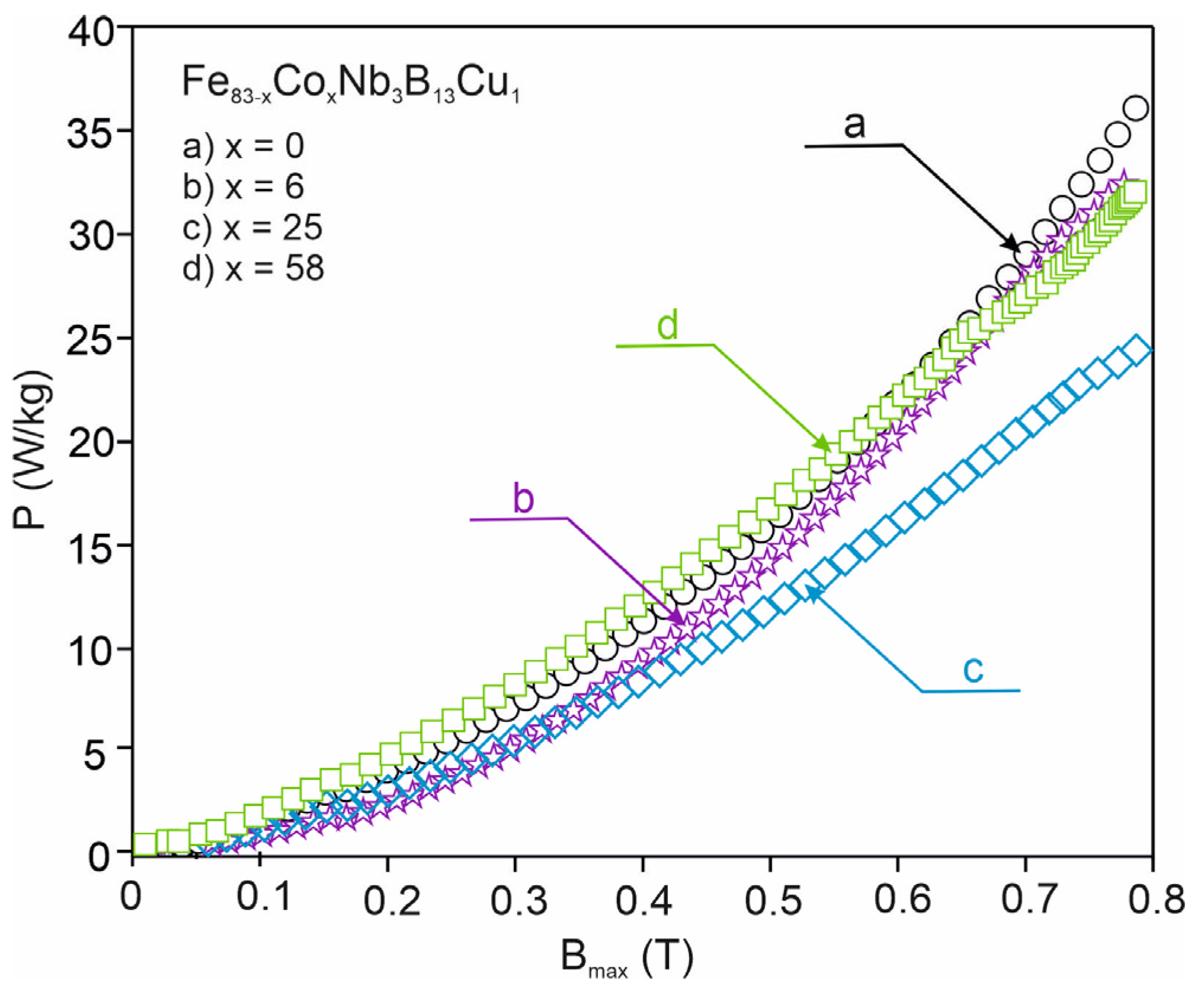
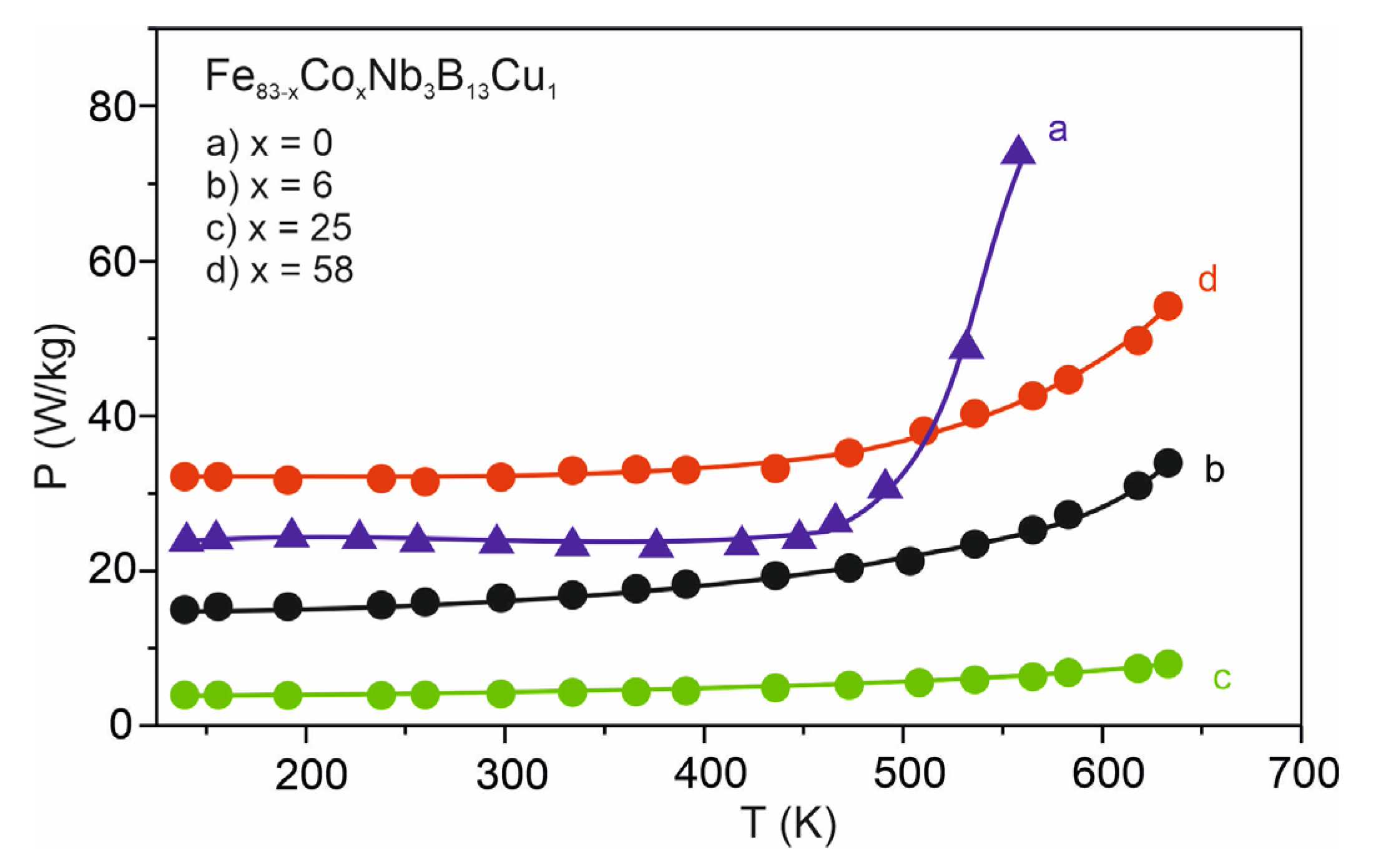
3. Results and Discussion
4. Conclusions
Author Contributions
Funding
Conflicts of Interest
References
- Wang, L.J.; Li, J.Q.; Wang, H.J. Application of nanocrystalline magnetic materials in electromechanical devices. Mater. Sci. Forum 2011, 694, 341–344. [Google Scholar] [CrossRef]
- Petzold, J. Application of nanocrystalline softmagnetic materials for modern electronic devices. Scr. Mater. 2003, 48, 895–901. [Google Scholar] [CrossRef]
- Li, Z.; Han, W.; Xin, Z.; Liu, Q.; Chen, J.; Loh, P.C. A review of magnetic core, core loss modeling and measurements in high-power high-frequency transformers. CPSS Trans. Power Electron. Appl. 2022, 7, 359–372. [Google Scholar] [CrossRef]
- Herzer, G.; Vazquez, M.; Knobel, M.; Zhukov, A.; Reininger, T.; Davies, H.A.; Grossinger, R.; Sanchez LI, J.L. Round table discussion: Present and future applications of nanocrystalline magnetic materials. J. Magn. Magn. Mater. 2005, 294, 252–266. [Google Scholar] [CrossRef]
- McHenry, M.E.; Willard, M.A.; Laughlin, D.E. Amorphous and nanocrystalline materials for applications as soft magnets. Prog. Mater. Sci. 1999, 44, 291–433. [Google Scholar] [CrossRef]
- Gheiratmand, T.; Hosseini, H.R.M. Finemet nanocrystalline soft magnetic alloy: Investigation of glass forming ability, crystallization mechanism, production techniques, magnetic softness and the effect of replacing the main constituents by other elements. J. Magn. Magn. Mater. 2016, 408, 177–192. [Google Scholar] [CrossRef]
- Wu, C.; Chen, H.; Lv, H.; Yan, M. Interplay of crystallization, stress relaxation and magnetic properties for FeCuNbSiB soft magnetic composites. J. Alloy. Compd. 2016, 673, 278–282. [Google Scholar] [CrossRef]
- Zhukova, V.; Corte-Leon, P.; Blanco, J.M.; Ipatov, M.; Gonzalez-Legarreta, L.; Gonzalez, A.; Zhukov, A. Development of Magnetically Soft Amorphous Microwires for Technological Applications. Chemosensors 2022, 10, 26. [Google Scholar] [CrossRef]
- Salaheldeen, M.; Garcia, A.; Corte-Leon, P.; Ipatov, M.; Zhukova, V.; Zhukov, A. Unveiling the effect of annealing on magnetic properties of nanocrystalline half-metallic Heusler Co2FeSi alloy glass-coated microwires. J. Mater. Res. Technol. 2022, 20, 4161–4172. [Google Scholar] [CrossRef]
- Nikolov, G.T.; Valchev, V.C. Nanocrystalline magnetic materials versus ferrites in power electronics. Procedia Earth Planet. Sci. 2009, 1, 1357–1361. [Google Scholar] [CrossRef] [Green Version]
- Rylko, M.S.; Hartnett, K.J.; Hayes, J.G.; Egan, M.G. Magnetic Material Selection for High Power High Frequency Inductors in DC-DC Converters. In Proceedings of the 2009 Twenty-Fourth Annual IEEE Applied Power Electronics Conference and Exposition, Washington, DC, USA, 15–19 February 2009. [Google Scholar]
- Hasiak, M.; Fukunaga, H.; Ciurzyńska, W.H.; Yamashiro, Y. Effect of Co addition on microstructure and magnetic properties of (Fe86-xCox)-Zr-B alloys. Scr. Mater. 2001, 44, 1465–1469. [Google Scholar] [CrossRef]
- Hasiak, M.; Zbroszczyk, J.; Ciurzyńska, W.H.; Olszewski, J.; Fukunaga, H.; Łukiewska, A.; Perduta, K.; Młyńczyk, A. Crystallization and magnetic behavior of (Fe1-xCox)85.4Zr5.8Nb1B6.8Cu1 (x=0, 0.1, 0.3, 0.5) alloys. Phys. Status Solidi (c) 2004, 1, 3463–3467. [Google Scholar] [CrossRef]
- Olszewski, J.; Zbroszczyk, J.; Fukunaga, H.; Ciurzyńska, W.H.; Świerczek, J.; Hasiak, M.; Perduta, K.; Łukiewska, A.; Młyńczyk, A. Microstructure studies of amorphous and nanocrystalline (Fe1-xCox)85.4Zr6.8-yMyB6.8Cu1 (x = 0, 0.1; y = 0 or 1, M = Mo, Nb or Nd) alloys. Nukleonika 2004, 49, S79–S83. [Google Scholar]
- Hasiak, M.; Ciurzyńska, W.H.; Yamashiro, Y. Microstructure and some magnetic properties of amorphous and nanocrystalline Fe-Cu-Nb-Si-B alloys. Mater. Sci. Eng. A 2000, 293, 261–266. [Google Scholar] [CrossRef]
- Herzer, G. Grain structure and magnetism of nanocrystalline ferromagnets. IEEE Trans. Magn. 1989, 25, 3327–3329. [Google Scholar] [CrossRef]
- Olszewski, J.; Zbroszczyk, J.; Fukunaga, H.; Ciurzyńska, W.H.; Narita, K.; Błachowicz, A.; Hasiak, M.; Wysłocki, B. Structure evolution and magnetic properties of annealed Fe77-x-yCuxNbySi13B10 alloys. J. Phys. IV 1998, 8, Pr2-131–Pr2-134. [Google Scholar] [CrossRef]
- Yoshizawa, Y.; Yamauchi, Y. Induced Magnetic Anisotropy and Thickness Dependence of Magnetic Properties in Nanocrystalline Alloy “Finemet”. IEEE Trans. Magn. 1990, 5, 1070–1076. [Google Scholar] [CrossRef]
- Skorvanek, I.; Marcin, J.; Krenicky, T.; Kovac, J.; Svec, P.; Janickovic, D. Inproved soft magnetic behavior in field-annealed nanocrystalline Hitperm alloys. J. Magn. Magn. Mater. 2006, 304, 203–207. [Google Scholar] [CrossRef]
- Pękała, M.; Kowalczyk, M.; Kulik, T. Magnetic study of Hitperm alloys (Fe0.5Co0.5)1–x –y –zMxByCuz (M = Hf, Zr, Nb). Phys. Status Solidi 2006, 203, 1561–1566. [Google Scholar] [CrossRef]
- Blazquez, J.S.; Conde, C.F.; Conde, A. Non-isothermal approach to isokinetic crystallization processes: Application to the nanocrystallization of HITPERM alloys. Acta Mater. 2005, 53, 2305–2311. [Google Scholar] [CrossRef]
- Yoshizawa, Y.; Fuji, S.; Ping, D.H.; Ohnuma, M.; Hono, K. Magnetic properties of nanocrystalline FeMCuNbSiB alloys (M: Co, Ni). Scr. Mater. 2003, 48, 863–868. [Google Scholar] [CrossRef]
- Kulik, T.; Wlazlowska, A.; Ferenc, J.; Latuch, J. Magnetically soft nanomaterials for high-temperature applications. IEEE Trans. Magn. 2002, 38, 3075–3077. [Google Scholar] [CrossRef]
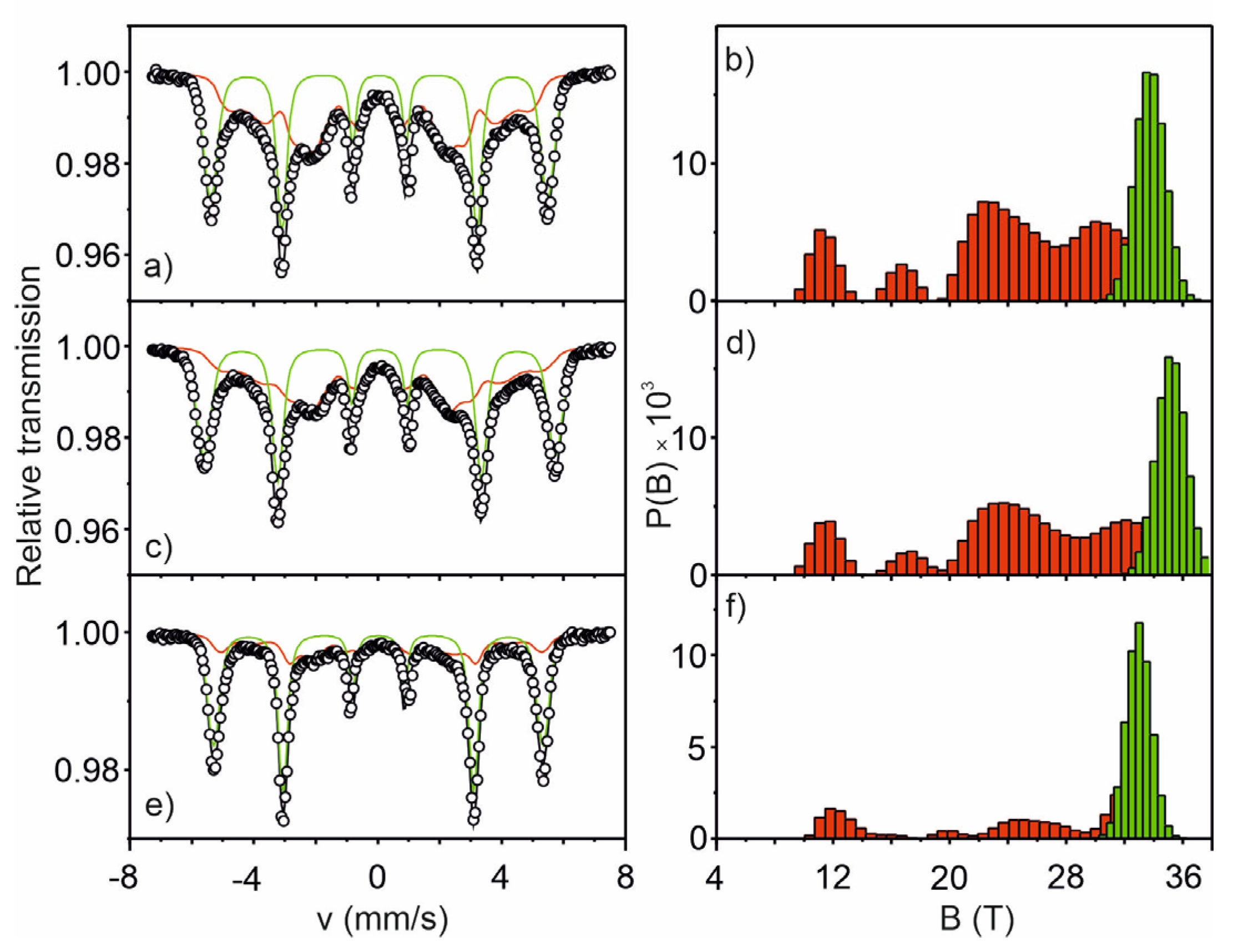
- Brand, R.A. Improving the validity of hyperfine field distributions from magnetic alloys. Nucl. Instrum. Methods Phys. Res. B 1987, 28, 398–416. [Google Scholar] [CrossRef]
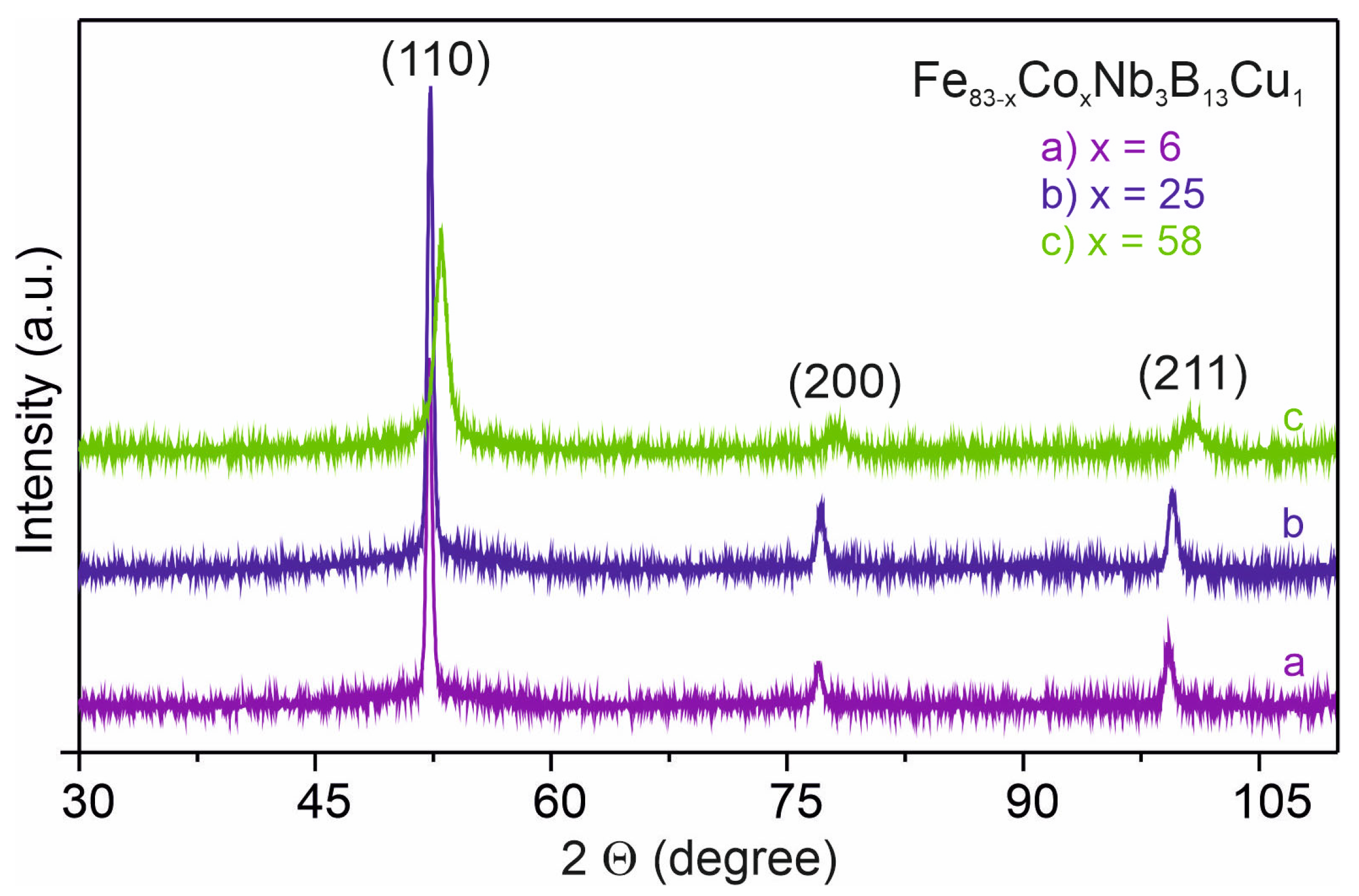
- Zbroszczyk, J.; Młyńczyk, A.; Olszewski, J.; Ciurzyńska, W.H.; Wysłocki, B.; Perduta, K.; Lelątko, J.; Nabiałek, M. Ordering of α-FeCo phase in the nanocrystalline Fe83−xCoxNb3B13Cu1 (x = 6, 25 or 41.5) alloys. Nukleonika 2007, 52, S29–S32. [Google Scholar]
- Zbroszczyk, J.; Młyńczyk, A.; Olszewski, J.; Ciurzyńska, W.H.; Hasiak, M.; Kolano, R.; Lelątko, J. Ordering of a-FeCo phase and magnetic properties of nanocrystalline Fe83−xCoxNb3B13Cu1 (x = 6, 25, 41.5, 58) alloys. J. Magn. Magn. Mater. 2006, 304, e727–e729. [Google Scholar] [CrossRef]
- Sundar, R.S.; Deevi, S.C. Soft magnetic FeCo alloys: Development, processing and properties. Int. Mater. Rev. 2005, 50, 157–192. [Google Scholar] [CrossRef]
- Kolano-Burian, A.; Łukiewski, M.; Zackiewicz, P.; Pilsniak, A.; Polak, M.; Łukiewska, A.; Hreczka, M.; Kolano, R.; Biskup, T.; Karpinski, M. Examination of magnetic properties of three-phase LLC and LCL filter chokes with multi-gap nanocrystalline block cores used in power electronics. J. Magn. Magn. Mater. 2022, 549, 169050. [Google Scholar] [CrossRef]
- Available online: https://trafeco.pl/en/chokes-of-drive-systems-with-cores-in-the-coreeco-technology/ (accessed on 9 March 2023).


| Parameters | Fe77Co6Nb3B13Cu1 | Fe58Co25Nb3B13Cu1 | Fe15Co58Nb3B13Cu1 |
|---|---|---|---|
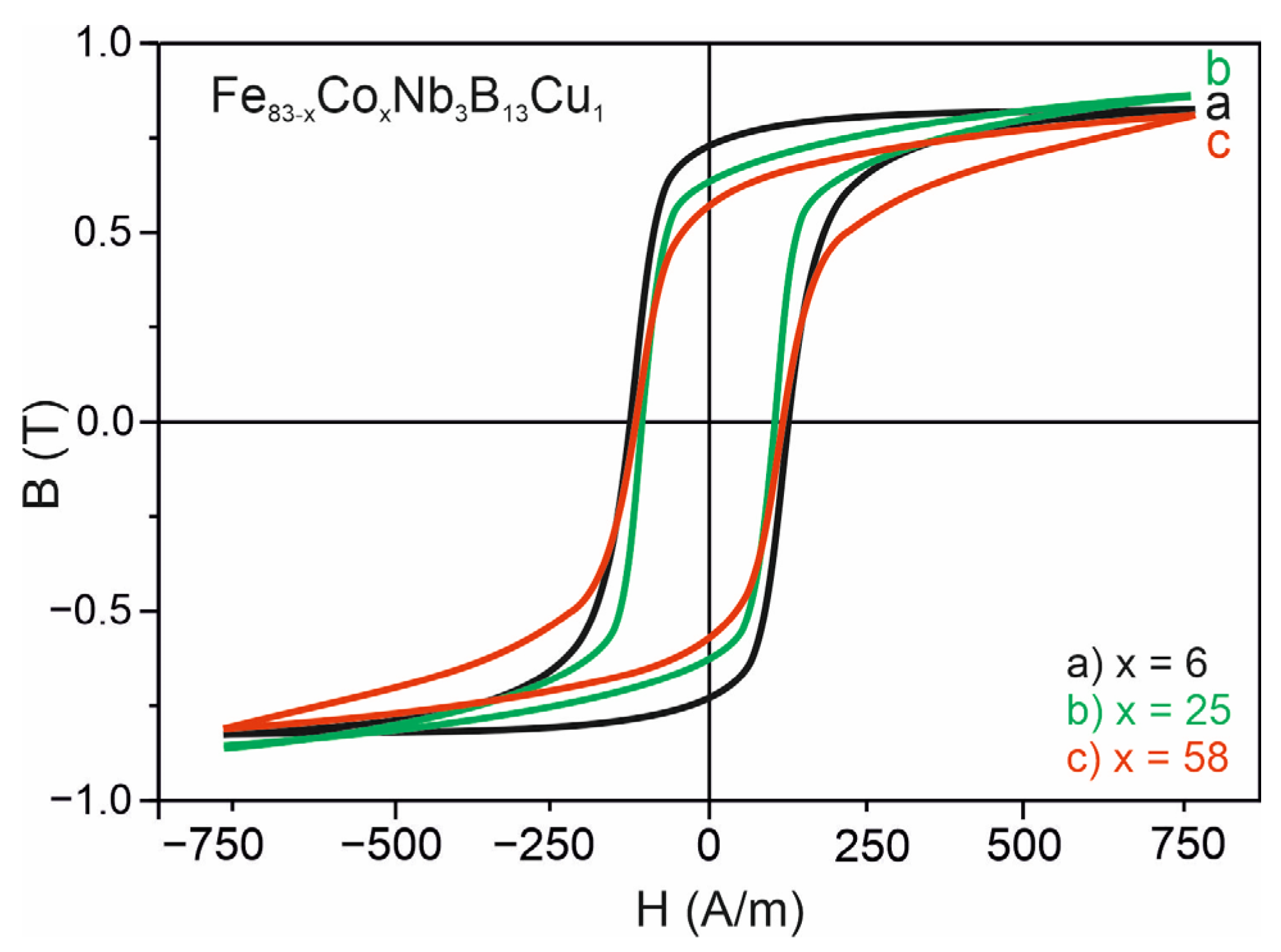
| Coercive field, Hc (A/m) | 120 ± 5 | 110 ± 4 | 115 ± 5 |
| Saturation magnetic flux density, Bs (T) | 0.84 ± 0.02 | 0.87 ± 0.02 | 0.82 ± 0.02 |
| Remanence, Br (T) | 0.73 ± 0.02 | 0.68 ± 0.02 | 0.57 ± 0.02 |
| Input Data of the Designed Choke | |
|---|---|
| Nominal voltage | 900 V DC |
| Insulation voltage against earth | 4 kV DC |
| Inductivity | 500 µH |
| Nominal current | 100 A DC |
| Magnetic linearity/overload | 150 A DC |
| Ripple Current | 8 kHz—25 Arms |
| 16 kHz—0.7 Arms | |
| 24 kHz—2.6 Arms | |
| 32 kHz—0.7 Arms | |
| 40 kHz—1.0 Arms | |
| Duty cycle | S1—continuous |
| Cooling | AN—air, natural |
| Max ambient temperature | 45 °C |
| Insulations class | Class F (Tmax = 155 °C) |
| Noise level | <50 dB |
| Core Materials | Fe83Nb3B13Cu1 | Fe77Co6Nb3B13Cu1 | Fe58Co25Nb3B13Cu1 |
|---|---|---|---|
| Losses *, P (W/kg) | 21.9 ± 0.1 | 20.8 ± 0.1 | 16.3 ± 0.1 |
| Saturation magnetic flux density Bs (T) | 1.21 ± 0.02 | 0.84 ± 0.02 | 0.87 ± 0.02 |
| Technical Parameters * | Reactor Type 2RTF—50 µH 100Adc 900Vdc T40F | ||
|---|---|---|---|
| Core material | Fe83Nb3B13Cu1 | Fe77Co6Nb3B13Cu1 | Fe58Co25Nb3B13Cu1 |
| Core weight | 17.8 kg | ||
| Flux density | 0.52 T | 0.48 T | 0.48 T |
| Core losses | 168 W | 166 W | 132 W |
| Core temperature rise | 73 K | 72 K | 67 K |
| Winding material | aluminum sheet 3× (0.2 × 125 mm) | ||
| Winding losses | 109 W | 128 W | 126 W |
| Winding temperature rise | 69 K | 70 K | 68 K |
| Number of turns | 30 turns | 32 turns | |
| Air gaps in the core per column | 8 × 0.55 mm | 8 × 0.65 mm | |
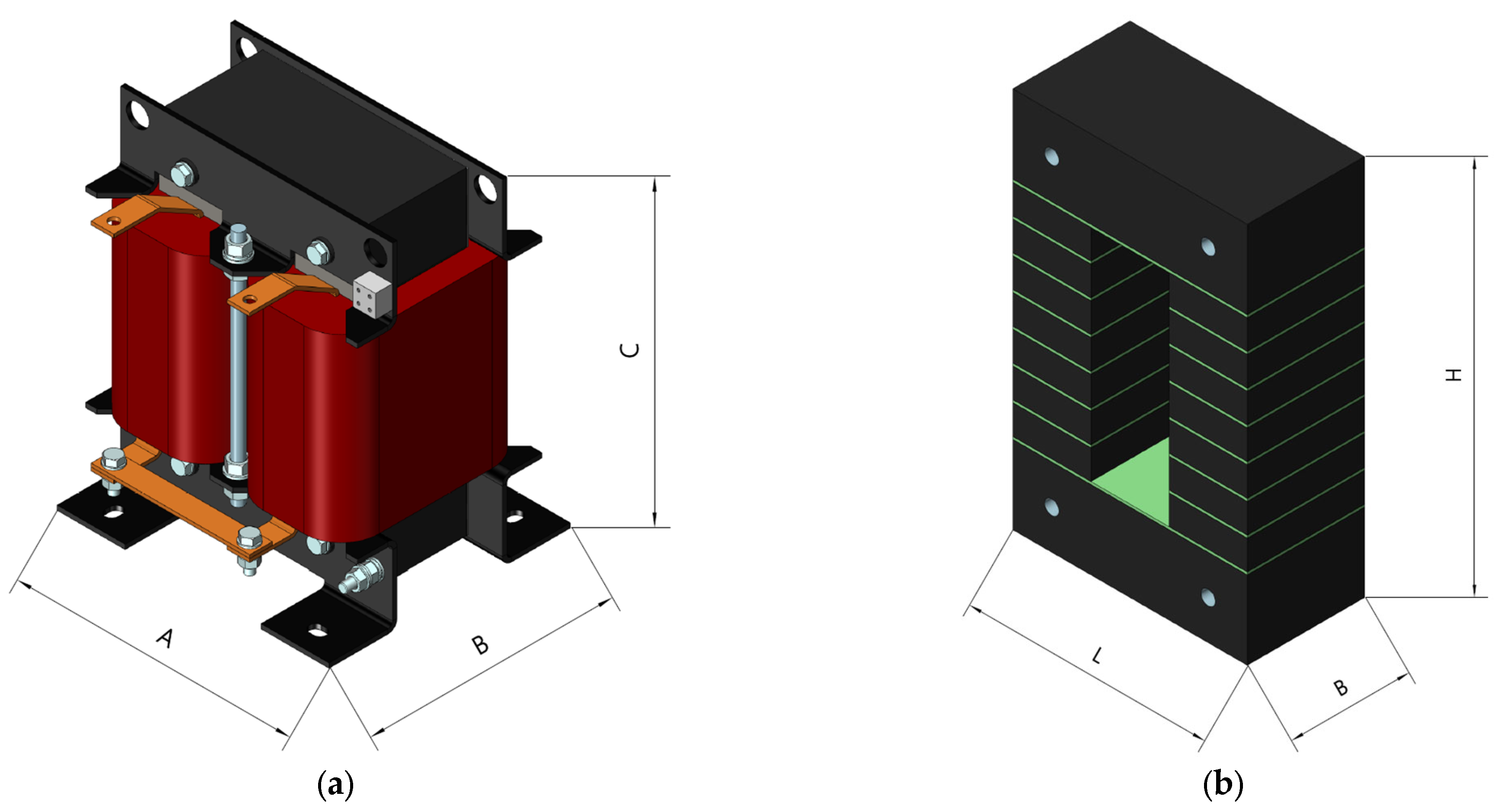
| Core dimensions L × B × H | 180 × 90 × 260 mm | ||
| Reactor weight | 20.2 kg | 20.4 kg | |
| Reactor dimensions A × B × C | 240 × 180 × 265 mm | ||
Disclaimer/Publisher’s Note: The statements, opinions and data contained in all publications are solely those of the individual author(s) and contributor(s) and not of MDPI and/or the editor(s). MDPI and/or the editor(s) disclaim responsibility for any injury to people or property resulting from any ideas, methods, instructions or products referred to in the content. |
© 2023 by the authors. Licensee MDPI, Basel, Switzerland. This article is an open access article distributed under the terms and conditions of the Creative Commons Attribution (CC BY) license (https://creativecommons.org/licenses/by/4.0/).
Share and Cite
Łukiewska, A.; Łukiewski, M.; Hasiak, M.; Łukiewska, H. Microstructure, Magnetic Properties, and Application of FINEMET-Type Alloys with Co Addition. Appl. Sci. 2023, 13, 4693. https://doi.org/10.3390/app13084693
Łukiewska A, Łukiewski M, Hasiak M, Łukiewska H. Microstructure, Magnetic Properties, and Application of FINEMET-Type Alloys with Co Addition. Applied Sciences. 2023; 13(8):4693. https://doi.org/10.3390/app13084693
Chicago/Turabian StyleŁukiewska, Agnieszka, Mirosław Łukiewski, Mariusz Hasiak, and Hanna Łukiewska. 2023. "Microstructure, Magnetic Properties, and Application of FINEMET-Type Alloys with Co Addition" Applied Sciences 13, no. 8: 4693. https://doi.org/10.3390/app13084693