

Microstructure and Fracture Behaviors of Oscillating Laser Welded 5A06 Aluminum Alloy Lock Butt Joint
Abstract
:1. Introduction
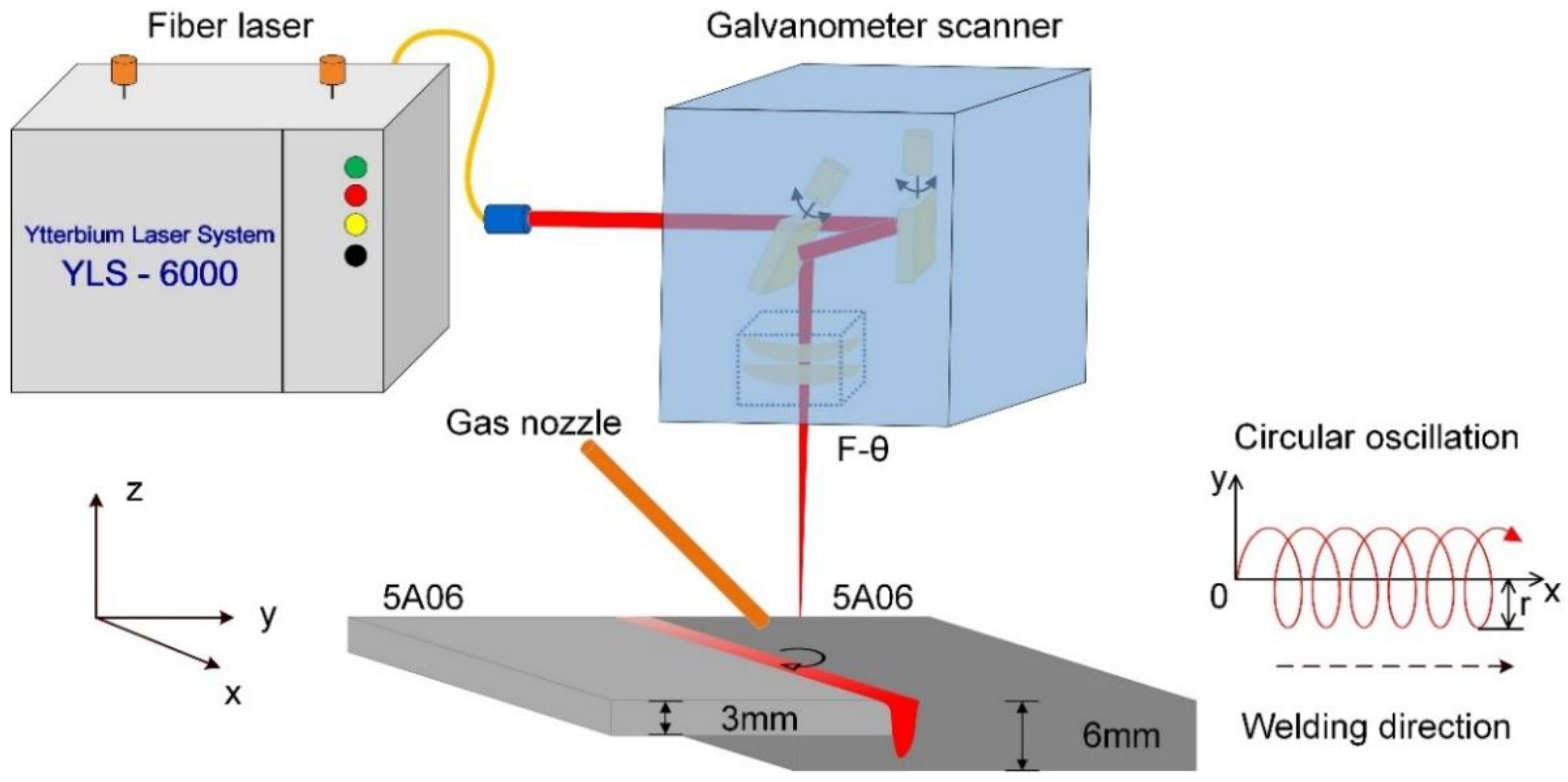
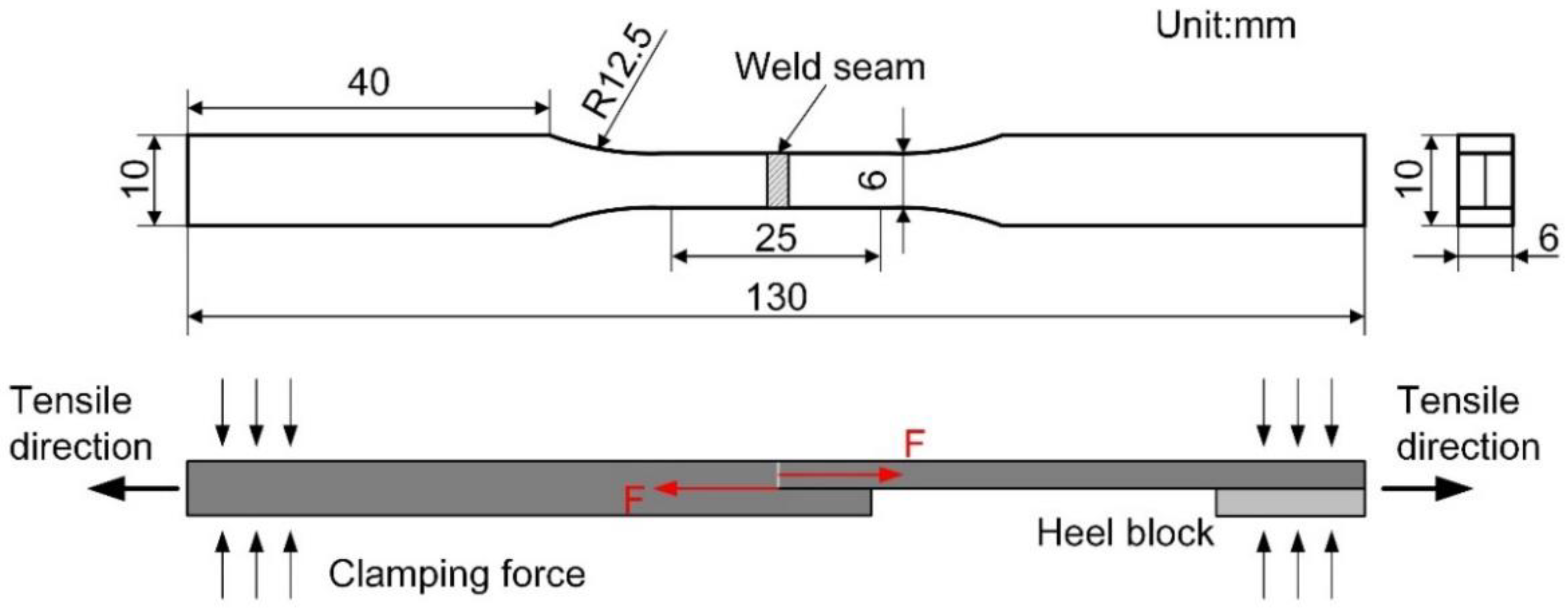
2. Experimental
3. Results and Discussion
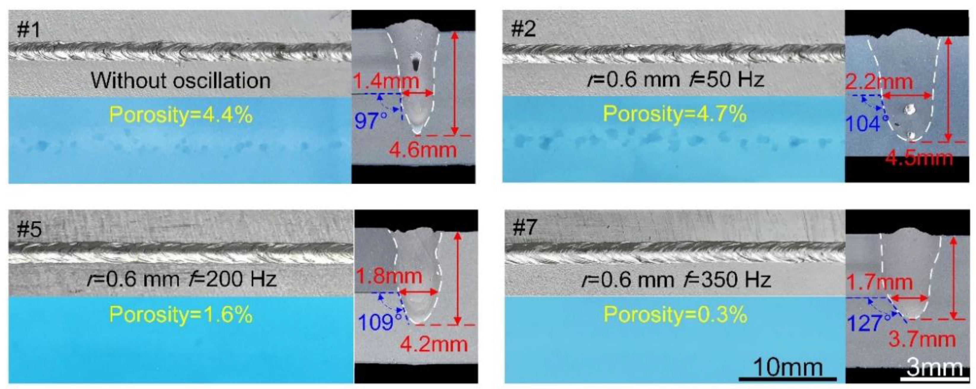
3.1. Weld Morphology
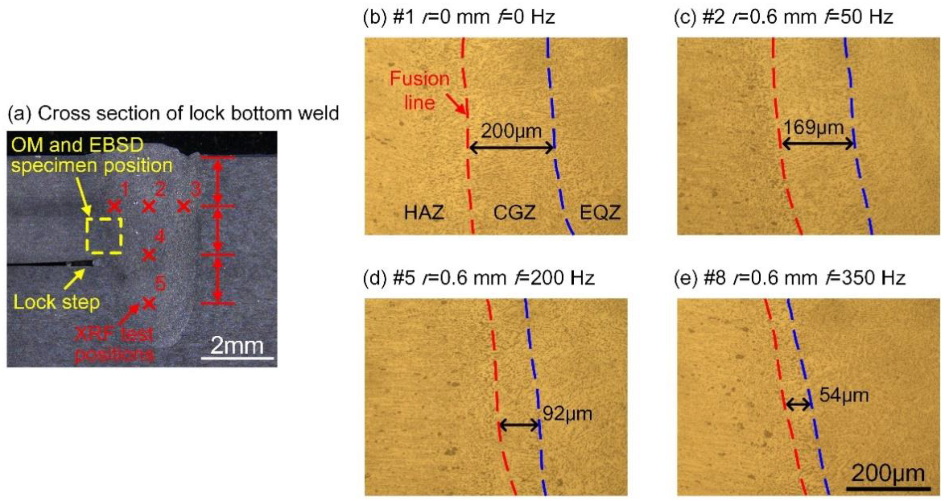
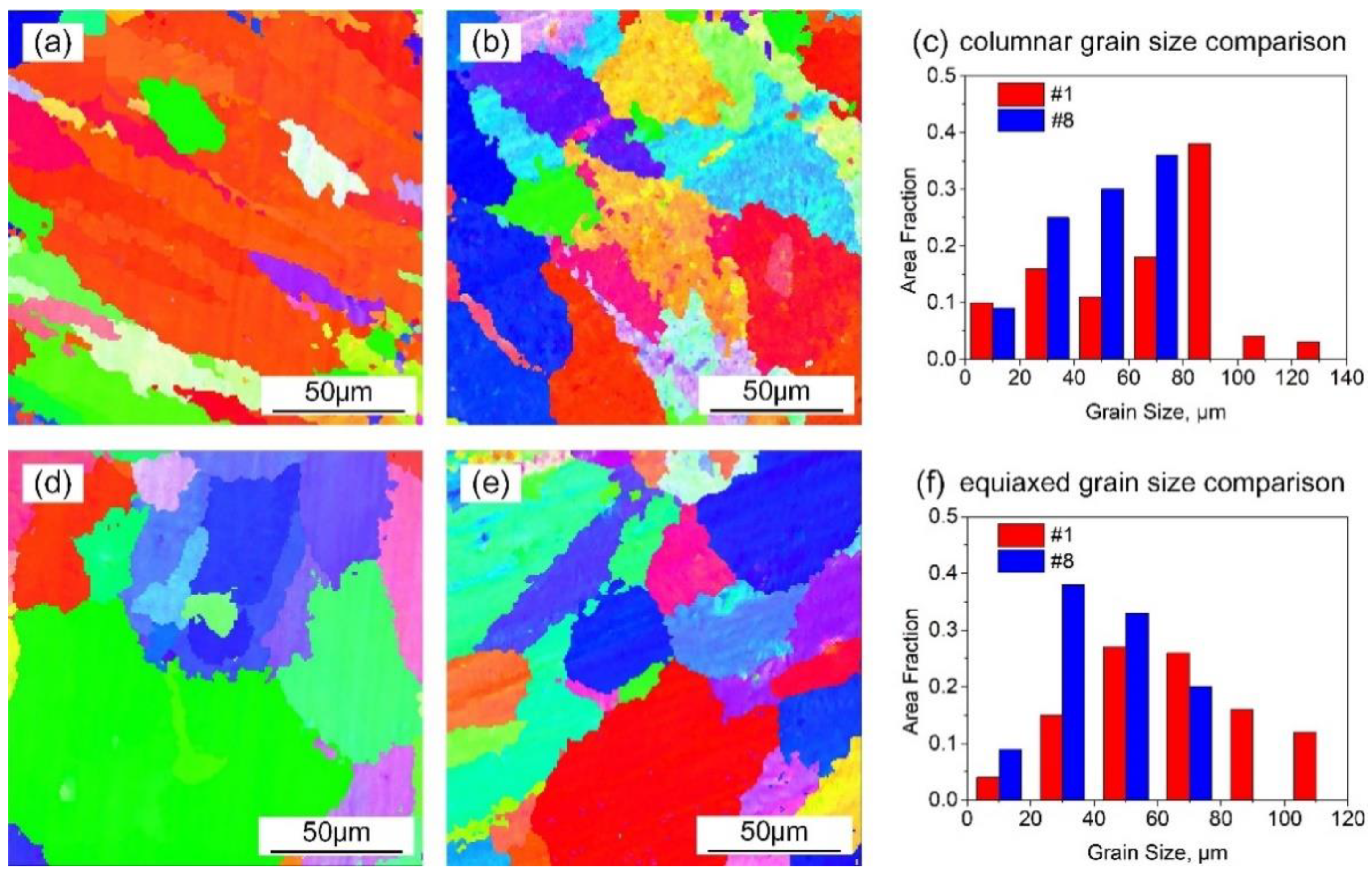
3.2. Microstructure
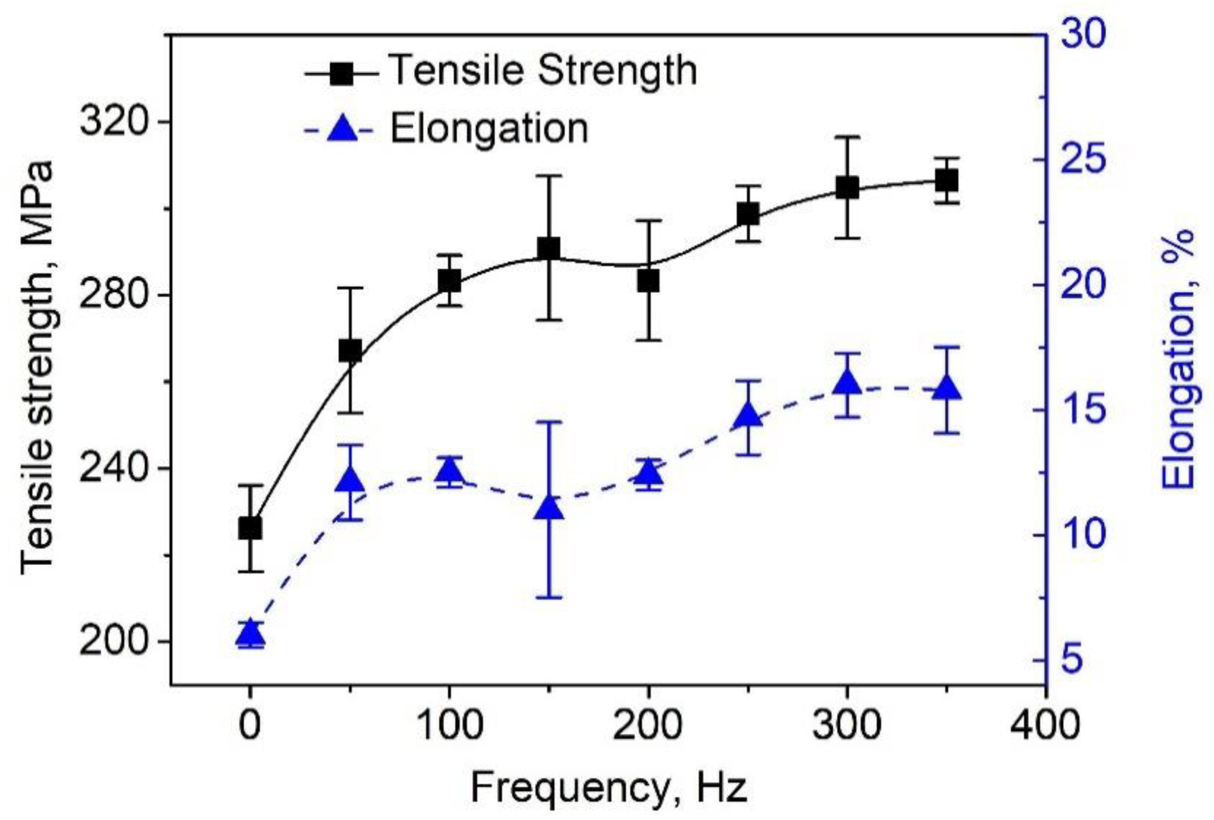
3.3. Tensile Properties
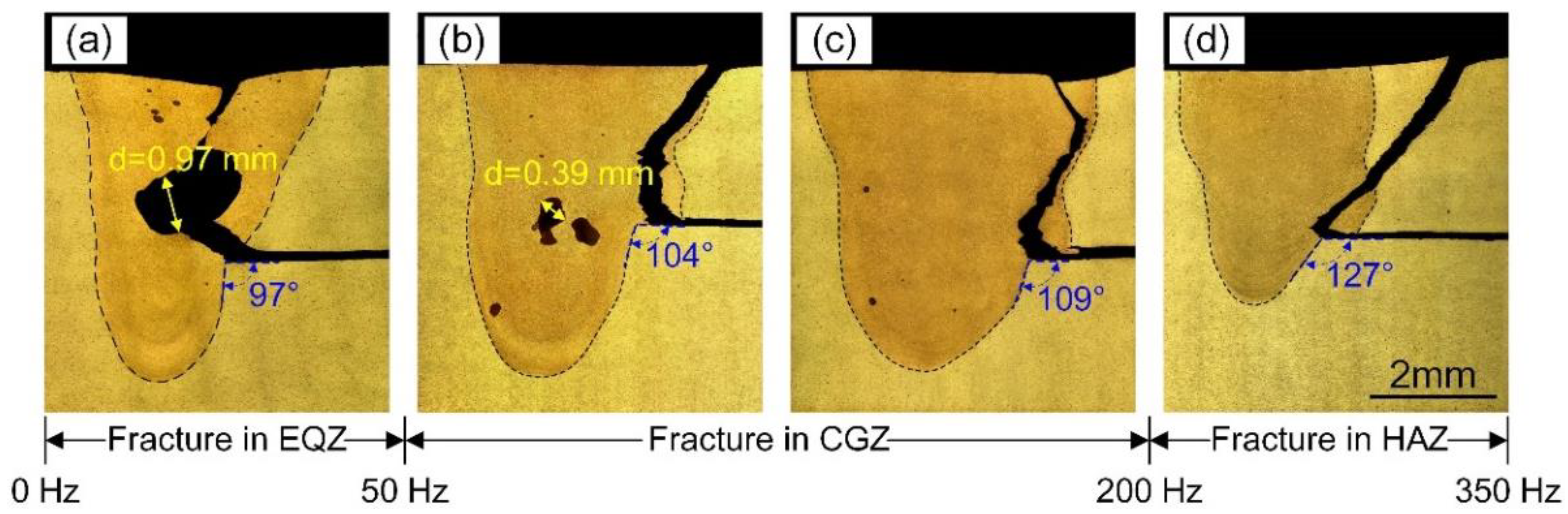
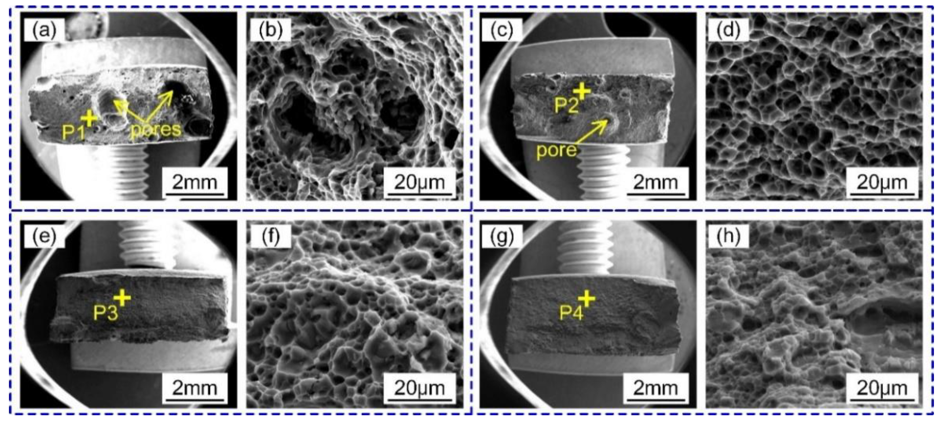
3.4. Fracture Modes and Morphologies
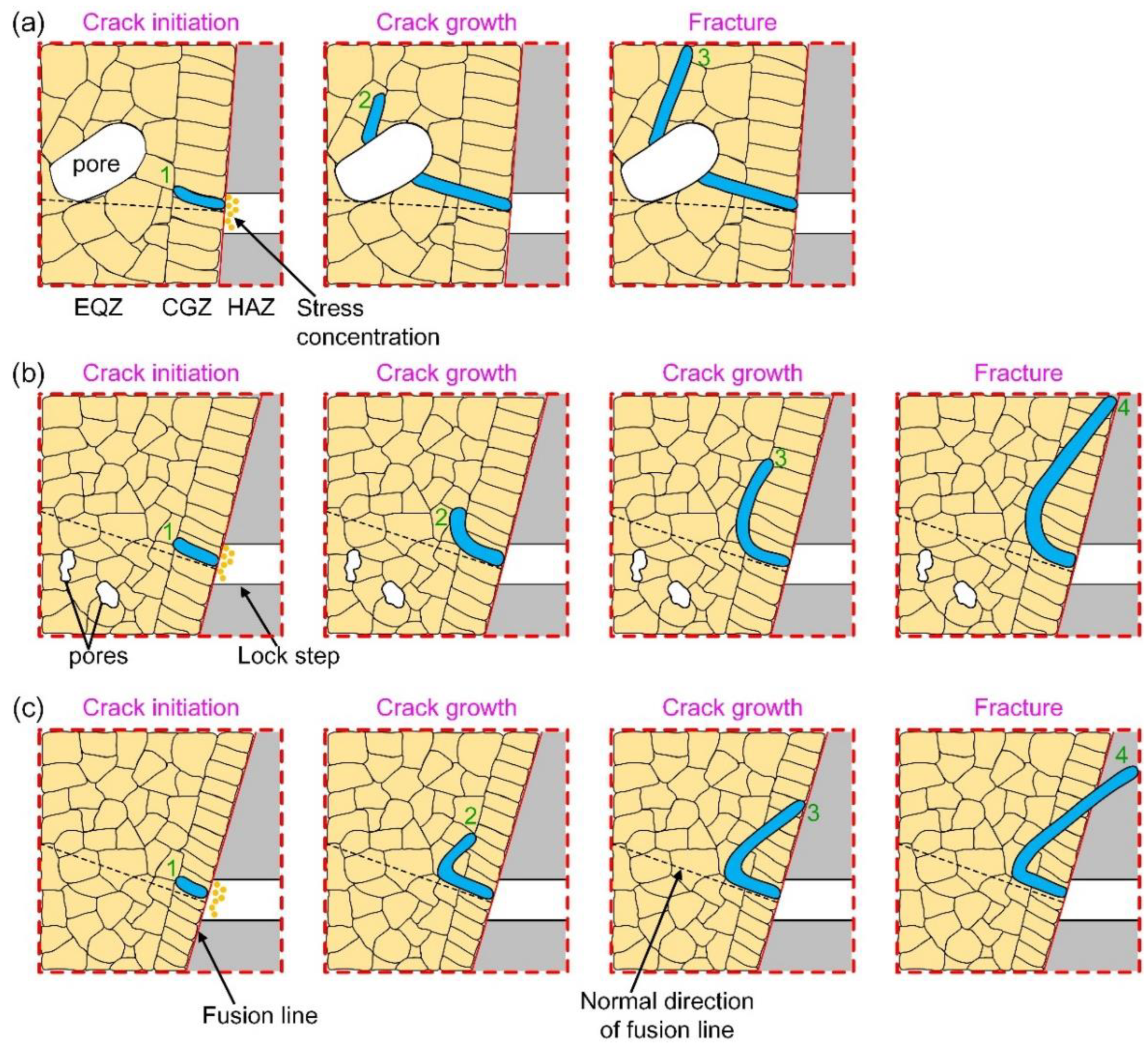
3.5. Fracture Mechanism
4. Conclusions
Author Contributions
Funding
Institutional Review Board Statement
Informed Consent Statement
Data Availability Statement
Conflicts of Interest
References
- Yang, B.; Tan, C.; Zhao, Y.; Wu, L.; Chen, B.; Song, X.; Zhao, H.; Feng, J. Influence of ultrasonic peening on microstructure and surface performance of laser-arc hybrid welded 5A06 aluminum alloy joint. J. Mater. Res. Technol. 2020, 9, 9576–9587. [Google Scholar] [CrossRef]
- Wu, D.; Li, W.; Liu, X.; Gao, Y.; Wen, Q.; Vairis, A. Effect of material configuration and welding parameter on weld formability and mechanical properties of bobbin tool friction stir welded Al-Cu and Al-Mg aluminum alloys. Mater. Charact. 2021, 182, 111518. [Google Scholar] [CrossRef]
- Shin, Y.C.; Wu, B.; Lei, S.; Cheng, G.J.; Yao, Y.L. Overview of Laser Applications in Manufacturing and Materials Processing in Recent Years. J. Manuf. Sci. Eng. 2020, 142, 110818. [Google Scholar] [CrossRef]
- Xie, J.; Chen, Y.; Yin, L.; Zhang, T.; Wang, S.; Wang, L. Microstructure and mechanical properties of ultrasonic spot welding TiNi/Ti6Al4V dissimilar materials using pure Al coating. J. Manuf. Process. 2021, 64, 473–480. [Google Scholar] [CrossRef]
- Kenda, M.; Klobčar, D.; Bračun, D. Condition based maintenance of the two-beam laser welding in high volume manufacturing of piezoelectric pressure sensor. J. Manuf. Syst. 2021, 59, 117–126. [Google Scholar] [CrossRef]
- Aminzadeh, A.; Parvizi, A.; Safdarian, R.; Rahmatabadi, D. Comparison between laser beam and gas tungsten arc tailored welded blanks via deep drawing. Proc. Inst. Mech. Eng. Part B J. Eng. Manuf. 2021, 235, 673–688. [Google Scholar] [CrossRef]
- Zhu, B.; Zhang, G.; Zou, J.; Ha, N.; Wu, Q.; Xiao, R. Melt flow regularity and hump formation process during laser deep penetration welding. Opt. Laser Technol. 2021, 139, 106950. [Google Scholar] [CrossRef]
- Hou, J.; Li, R.; Xu, C.; Li, T.; Shi, Z. A comparative study on microstructure and properties of pulsed laser welding and continuous laser welding of Al-25Si-4Cu-Mg high silicon aluminum alloy. J. Manuf. Process. 2021, 68, 657–667. [Google Scholar] [CrossRef]
- Lin, R.; Wang, H.-P.; Lu, F.; Solomon, J.; Carlson, B.E. Numerical study of keyhole dynamics and keyhole-induced porosity formation in remote laser welding of Al alloys. Int. J. Heat Mass Transf. 2017, 108, 244–256. [Google Scholar] [CrossRef]
- Tao, W.; Yang, S. Weld zone porosity elimination process in remote laser welding of AA5182-O aluminum alloy lap-joints. J. Mater. Process. Technol. 2020, 286, 116826. [Google Scholar] [CrossRef]
- Feng, Y.; Gao, X.; Zhang, Y.; Peng, C.; Gui, X.; Sun, Y.; Xiao, X. Simulation and experiment for dynamics of laser welding keyhole and molten pool at different penetration status. Int. J. Adv. Manuf. Technol. 2021, 112, 2301–2312. [Google Scholar] [CrossRef]
- Qi, N.; Zhan, X.; Chen, S.; Chen, D.; He, S. Effect of Laser Power on Tensile Performance of TA15 Laser-Welded Lock Bottom Joint. Met. Mater. Int. 2021, 27, 4645–4656. [Google Scholar] [CrossRef]
- Zhang, R.; Tang, X.; Xu, L.; Lu, F.; Cui, H. Study of molten pool dynamics and porosity formation mechanism in full penetration fiber laser welding of Al-alloy. Int. J. Heat Mass Transf. 2020, 148, 119089. [Google Scholar] [CrossRef]
- Tan, Z.; Pang, B.; Oliveira, J.; Chen, L.; Bu, X.; Wang, Z.; Cong, B.; Zeng, Z. Effect of S-curve laser power for power distribution control on laser oscillating welding of 5A06 aluminum alloy. Opt. Laser Technol. 2022, 149, 107909. [Google Scholar] [CrossRef]
- Ahmadi, M.; Tabary, S.B.; Rahmatabadi, D.; Ebrahimi, M.; Abrinia, K.; Hashemi, R. Review of selective laser melting of magnesium alloys: Advantages, microstructure and mechanical characterizations, defects, challenges, and applications. J. Mater. Res. Technol. 2022, 19, 1537–1562. [Google Scholar] [CrossRef]
- Liu, T.; Mu, Z.; Hu, R.; Pang, S. Sinusoidal oscillating laser welding of 7075 aluminum alloy: Hydrodynamics, porosity formation and optimization. Int. J. Heat Mass Transf. 2019, 140, 346–358. [Google Scholar] [CrossRef]
- Chen, L.; Mi, G.; Zhang, X.; Wang, C. Effects of sinusoidal oscillating laser beam on weld formation, melt flow and grain structure during aluminum alloys lap welding. J. Mater. Process. Technol. 2021, 298, 117314. [Google Scholar] [CrossRef]
- Fetzer, F.; Sommer, M.; Weber, R.; Weberpals, J.-P.; Graf, T. Reduction of pores by means of laser beam oscillation during remote welding of AlMgSi. Opt. Lasers Eng. 2018, 108, 68–77. [Google Scholar] [CrossRef]
- Bi, J.; Liu, Z.; Chi, J.; Wang, H.; Tan, C.; Jia, X.; Yang, Z.; Starostenkov, M.D.; Dong, G. Formation mechanisms and control strategies of FQZ softening in Al–Li alloy welded joint. J. Mater. Res. Technol. 2023, 23, 2810–2823. [Google Scholar] [CrossRef]
- Zhang, C.; Yu, Y.; Chen, C.; Zeng, X.; Gao, M. Suppressing porosity of a laser keyhole welded Al-6Mg alloy via beam oscillation. J. Mater. Process. Technol. 2020, 278, 116382. [Google Scholar] [CrossRef]
- Hu, K.; Muneer, W.; Zhang, J.; Zhan, X. Effect of beam oscillating frequency on the microstructure and mechanical properties of dissimilar laser welding of AA2060 and AA6061 alloy. Mater. Sci. Eng. A 2022, 832, 142431. [Google Scholar] [CrossRef]
- Wang, L.; Gao, M.; Zhang, C.; Zeng, X. Effect of beam oscillating pattern on weld characterization of laser welding of AA6061-T6 aluminum alloy. Mater. Des. 2016, 108, 707–717. [Google Scholar] [CrossRef]
- Wang, Z.; Oliveira, J.; Zeng, Z.; Bu, X.; Peng, B.; Shao, X. Laser beam oscillating welding of 5A06 aluminum alloys: Microstructure, porosity and mechanical properties. Opt. Laser Technol. 2019, 111, 58–65. [Google Scholar] [CrossRef]
- Li, S.; Mi, G.; Wang, C. A study on laser beam oscillating welding characteristics for the 5083 aluminum alloy: Morphology, microstructure and mechanical properties. J. Manuf. Process. 2020, 53, 12–20. [Google Scholar] [CrossRef]
- Deng, H.; Chen, Y.; Jia, Y.; Pang, Y.; Zhang, T.; Wang, S.; Yin, L. Microstructure and mechanical properties of dissimilar NiTi/Ti6Al4V joints via back-heating assisted friction stir welding. J. Manuf. Process. 2021, 64, 379–391. [Google Scholar] [CrossRef]
- Hagenlocher, C.; Sommer, M.; Fetzer, F.; Weber, R.; Graf, T. Optimization of the solidification conditions by means of beam oscillation during laser beam welding of aluminum. Mater. Des. 2018, 160, 1178–1185. [Google Scholar] [CrossRef]
- Gong, J.; Li, L.; Meng, S.; Huang, R.; Zou, J.; Cao, H. Study on stability and microstructure properties of oscillating laser welded 5A06 alloy with narrow gap. Opt. Laser Technol. 2022, 155, 108360. [Google Scholar] [CrossRef]
- Shi, L.; Li, X.; Jiang, L.; Gao, M. Numerical study of keyhole-induced porosity suppression mechanism in laser welding with beam oscillation. Sci. Technol. Weld. Join. 2021, 26, 349–355. [Google Scholar] [CrossRef]
- Moshtaghi, M.; Safyari, M.; Mori, G. Combined thermal desorption spectroscopy, hydrogen visualization, HRTEM and EBSD investigation of a Ni–Fe–Cr alloy: The role of hydrogen trapping behavior in hydrogen-assisted fracture. Mater. Sci. Eng. A 2022, 848, 143428. [Google Scholar] [CrossRef]
- Zhu, M.; Yang, S.; Bai, Y.; Fan, C. Microstructure and fatigue damage mechanism of 6082-T6 aluminium alloy welded joint. Mater. Res. Express 2021, 8, 056505. [Google Scholar] [CrossRef]
- Schempp, P.; Cross, C.E.; Hacker, R.; Pittner, A.; Rethmeier, M. Influence of grain size on mechanical properties of aluminium GTA weld metal. Weld. World 2013, 57, 293–304. [Google Scholar] [CrossRef]
- Zhao, Y.; Zhan, X.; Chen, S.; Bai, M.; Gong, X. Study on the shear performance and fracture mechanism of T-joints for 2219 aluminum alloy by dual laser-beam bilateral synchronous welding. J. Alloys Compd. 2020, 847, 156511. [Google Scholar] [CrossRef]
- Mesbah, M.; Fadaeifard, F.; Nasiri-Tabrizi, B.; Matori, K.; Basirun, W. The impacts of grain boundary on the scattering of intermetallics in friction-stir-welded AA6061-T6. Mater. Lett. 2021, 300, 130206. [Google Scholar] [CrossRef]


| Element | Si | Fe | Cu | Mn | Mg | Zn | Ti | Al |
|---|---|---|---|---|---|---|---|---|
| Content | 0.4 | 0.4 | 0.1 | 0.5 | 6.8 | 0.2 | 0.02 | Bal |
| Welding Parameters | #1 | #2 | #3 | #4 | #5 | #6 | #7 | #8 | #9 | #10 | #11 |
|---|---|---|---|---|---|---|---|---|---|---|---|
| P (kW) | 3.0 | 3.5 | 3.5 | 3.5 | 3.5 | 3.5 | 3.5 | 3.5 | 3.5 | 3.5 | 3.5 |
| v (m min−1) | 2.0 | 2.0 | 2.0 | 2.0 | 2.0 | 2.0 | 2.0 | 2.0 | 2.0 | 2.0 | 2.0 |
| r (mm) | - | 0.6 | 0.6 | 0.6 | 0.6 | 0.6 | 0.6 | 0.6 | 0.4 | 0.8 | 1.0 |
| f (Hz) | - | 50 | 100 | 150 | 200 | 250 | 300 | 350 | 200 | 200 | 200 |
| Samples | Position | Mg | Stdev | |
|---|---|---|---|---|
| Transverse | Longitudinal | |||
| BM-5A06 | - | 6.16 | - | - |
| without oscillation | 1 | 6.11 | 0.17 | 0.15 |
| 2 | 5.8 | |||
| 3 | 5.71 | |||
| 4 | 5.8 | |||
| 5 | 6.13 | |||
| r = 0.6 mm f = 350 Hz | 1 | 6.22 | 0.13 | 0.12 |
| 2 | 6.02 | |||
| 3 | 5.91 | |||
| 4 | 6.06 | |||
| 5 | 6.29 | |||
Disclaimer/Publisher’s Note: The statements, opinions and data contained in all publications are solely those of the individual author(s) and contributor(s) and not of MDPI and/or the editor(s). MDPI and/or the editor(s) disclaim responsibility for any injury to people or property resulting from any ideas, methods, instructions or products referred to in the content. |
© 2023 by the authors. Licensee MDPI, Basel, Switzerland. This article is an open access article distributed under the terms and conditions of the Creative Commons Attribution (CC BY) license (https://creativecommons.org/licenses/by/4.0/).
Share and Cite
Lu, Y.; Lai, J.; Pang, J.; Li, X.; Zhang, C.; Gao, M. Microstructure and Fracture Behaviors of Oscillating Laser Welded 5A06 Aluminum Alloy Lock Butt Joint. Appl. Sci. 2023, 13, 3381. https://doi.org/10.3390/app13063381
Lu Y, Lai J, Pang J, Li X, Zhang C, Gao M. Microstructure and Fracture Behaviors of Oscillating Laser Welded 5A06 Aluminum Alloy Lock Butt Joint. Applied Sciences. 2023; 13(6):3381. https://doi.org/10.3390/app13063381
Chicago/Turabian StyleLu, Yang, Jian Lai, Junping Pang, Xin Li, Chen Zhang, and Ming Gao. 2023. "Microstructure and Fracture Behaviors of Oscillating Laser Welded 5A06 Aluminum Alloy Lock Butt Joint" Applied Sciences 13, no. 6: 3381. https://doi.org/10.3390/app13063381