Article

Assessment of Changes in the Abrasiveness of Solid Particles in Hydraulic Mixtures Pumped with ESPs

1
Department of Mining Electromechanics, Perm National Research Polytechnic University, 614990 Perm, Russia
2
Department of Mechanical Engineering, Saint Petersburg Mining University, 199106 Saint Petersburg, Russia
*
Author to whom correspondence should be addressed.
Appl. Sci. 2023, 13(3), 1885; https://doi.org/10.3390/app13031885
Submission received: 19 December 2022 / Revised: 11 January 2023 / Accepted: 27 January 2023 / Published: 1 February 2023
(This article belongs to the Special Issue Focus on Fatigue and Fracture of Engineering Materials)

Abstract

:
The statistics of using downhole electric submersible pump (ESP) units in the oil fields of Eurasia show that hydroabrasive wear is a common cause of ESP emergency failures. The authors of this study theoretically and experimentally investigated the peculiarities of water–abrasive wear of ESP components. The research methodology and construction of the laboratory bench are described, and the results of experimental studies of determination of changes in the abrasivity index of impurity particles contained in the mixture pumped with the working stages of an ESP section are given. It is shown that large particles of mechanical impurities in contact with the metal of the working stages are subjected to intensive grinding of up to 0.25…0.3 mm; after that, particle size remains practically unchanged. An increased abrasiveness index of mechanical impurities causes an increase in the intensity of wear of interstage seals along the flow of a water–abrasive mixture (from the inlet to the outlet of the pumping section). Based on the obtained results, recommendations for selection of devices for formation-fluid cleaning during development and operation of oil wells are given. The relevance of work on improving the design of interstage seals of ESP units is substantiated.

1. Introduction

Well-oil production in the fields of the countries of the Eurasian region is carried out with widespread use of electric submersible pump units (ESP units). These units are characterized with high energy efficiency in operation of wells with medium and high rates (more than 40 m3/day). The introduction of intermittent well-operation technology in oil fields and mastery of the production of small-sized ESP units makes it possible to expand the area of use of these pumping units to wells with low flow rates. As a result, for example, in the fields of the Urals and Western Siberia, more than 60% of oil wells are equipped with ESP units. These plants produce more than 80% of oil in Russia [1,2].
ESP units are often operated under difficult conditions, which can lead to high risks of premature unit failure. Elimination of ESP-unit failures entails significant financial and time costs for the oil producer, since each emergency stop requires expensive tripping operations [3,4].
A significant part of ESP-unit emergency failures (over 30% of the total number) is caused by hydroabrasive wear of electric submersible pump units and connected devices [5]. In the most severe situations, the impact of abrasive particles contained in pumped well fluid is accompanied by cutting of the guide vanes and pump housings (Figure 1), followed by submersible electric motors and parts of the ESP unit falling to the bottom of the well [6]. Elimination of such failures removes the need to perform technically complex and laborious fishing operations [4,7].
Especially unfavorable operating conditions for ESP units are characterized with wells that are put into operation after hydraulic fracturing. Removal of loose proppant during development of such wells reduces the operating time of electric submersible pumps to several days [8,9,10].
Several works [11,12,13] are devoted to the study of the process of hydroabrasive wear of ESP components. Attention in the process of ESP design is mainly paid to selection of wear-resistant materials of the working stages, placement and improvement of bearing-support designs, development of wear-resistant designs for guiding apparatuses and protection from cutting. The peculiarities of the hydroabrasive-wear process of interstage seals, for example, remain insufficiently investigated.
Known methods of calculation of the hydroabrasive-wear rate of interstage seals for ESP installations do not take into account changes in the sizes and shapes of the impurity particles contained in a pumped hydroabrasive mixture as they pass through the working stages of the pump. They also do not take into account the nonuniformity of seal wear depending on the location in the pumping section. In this case, the rate of seal hydroabrasive wear differs significantly, as not only do values of pressure drop on seals differ but also abrasiveness of mechanical-impurity changes relative to the initial.
The specified has caused urgency of research of an estimation of abrasiveness change for solid particles in hydromechanical mixes pumped with ESP units, with the purpose of development of technical decisions directed toward minimization of consequences of hydroabrasive wear of ESP-unit knots and details.

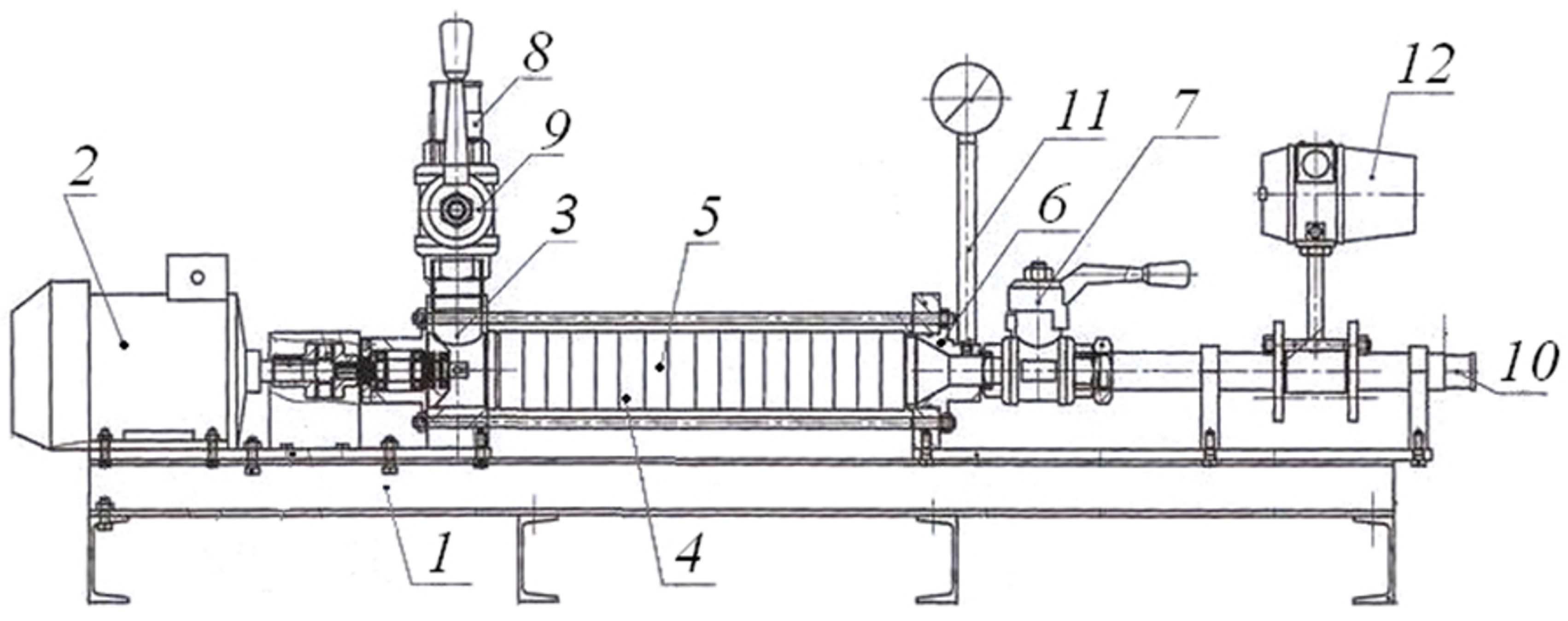
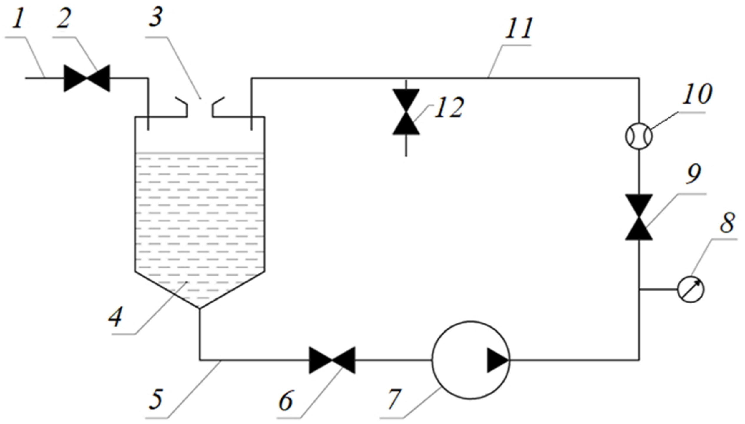
2. Materials and Methods

Hydroabrasive wear is a common phenomenon in many fields of technology. It occurs when a pumped liquid that contains solid impurity particles (a water–abrasive mixture) interacts with pipelines, pump parts, valves, switchgear assemblies, etc. [14,15].
The abrasive particles contained in borehole fluids are classified based on origin, as follows:
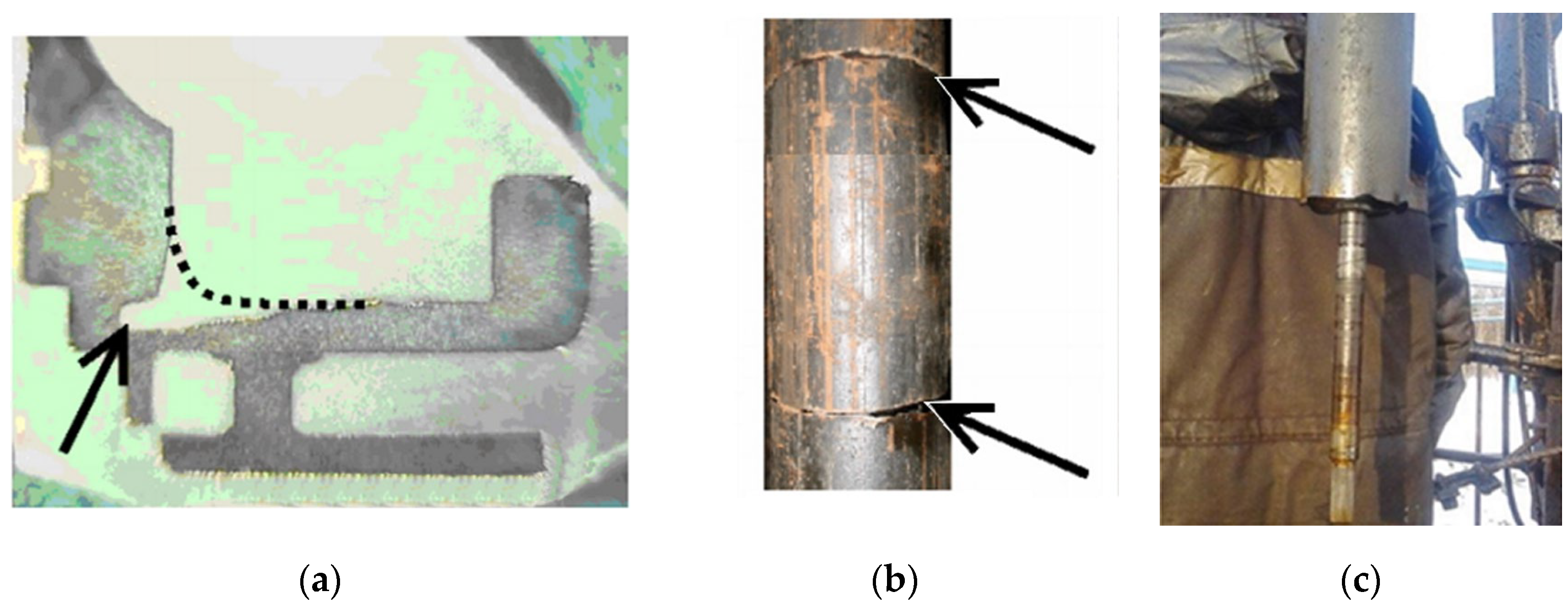
Loose proppant after hydraulic fracturing;
Particles of reservoir rocks;
Corrosion products of downhole equipment;
Solid particles from well-kill solutions;
Sediment particles formed during mixing of chemically incompatible waters [16,17].
The composition of a mechanical impurity can be single- or multicomponent, and its concentration, as a rule, is not a constant value. High content of mechanical impurities in pumped liquid is typical for the stages of well development, startup after current and overhaul. A short-term increase in concentration of mechanical impurities is observed during the startups of ESP units that operate in periodic modes, as well as during changing of the parameters of reservoir-pressure maintenance systems.
It is known that intensive hydroabrasive wear is accompanied by operation of electric centrifugal pumps at the following concentrations of mechanical impurities in pumped well fluid:
For pumps in the normal version—C = 1 g/m3;
For pumps in the wear-resistant version—C = 3 g/m3.
If the concentration of mechanical impurities in a well fluid is more than C = 5 g/m3, in addition to hydroabrasive wear, the corresponding ESP-unit operation will be accompanied by significant vibrations and a high probability of pump-rotor jamming [16,18,19,20,21].
The wear of the working stages of electric centrifugal pumps under the influence of abrasive particles of mechanical impurities is a multifactorial process, the intensity of which in general can be determined with Equation (1):
d K i d t = f ( R , F , ρ , H c , C , K , H d , F d , ω )
where Ki—relative change in the mass of a wearing part of the working stage of an ESP; t—time of action of abrasive particles on this wearing part; dKi/dt—rate of hydroabrasive wear; R, F, ρ, Hc and C—size, shape, density, hardness and concentration of abrasive particles of mechanical impurities, respectively; K—corrosiveness of the medium; Hd—hardness of the surface of the wearing part; Fd—surface shape of the wearing part; and ω—rotation frequency of the pump drive shaft [18].
The influence of geometric parameters and physical and mechanical properties of particles of mechanical impurities on wear capacity is taken into account in the methodology of the American Petroleum Institute (API) and estimated via the value of the complex index of abrasiveness of mechanical impurities, which is generally described with Equation (2):
A I = f ( R , F , ρ , H c )
where AI—abrasiveness index of mechanical impurities,%.
Quantitatively, the value of the abrasion index, AI, is determined with Equation (3):
A I = 10   ·   ( 2 K r K s ) + 0.3   ·   M 0.25 % + 0.25   ·   ( M i r % + M q % )
where M−0.25% is the mass fraction of abrasive particles of mechanical impurities with a size of less than 0.25 mm,%; Kr is the particle-shape coefficient of the mechanical impurities, found according to the API method; Ks is the sphericity coefficient of the mechanical-impurity particles, found according to the API method; Mir% is the mass fraction of insoluble residue (particles insoluble in acid),%; and Mq% is the fraction of quartz particles in the total mechanical-impurity mass,% [7].
Analysis of formula (3) shows that the largest influence on abrasiveness of particles of mechanical impurities that interact with parts of electric centrifugal pumps is made by the sizes and shapes of solid particles: their roundness and sphericality. A diagram for visual determination of the values of the coefficients of roundness, Kr, and sphericality, Ks, of particulate mechanical impurities is shown in Figure 2 [22].
Most of the methods used to protect submersible electric centrifugal pumps from hydroabrasive wear are aimed at reducing the concentration and average particle size of mechanical impurities that pass through the pump stages in pumped liquid flow, increasing the abrasion resistance of pump stage materials and improving interstage seals [23].
The shapes and sizes of the solid particles contained in a liquid stream change as they pass through the stages of centrifugal pumps; mechanical-impurity particles are ground, while the values of the circularity and sphericality coefficients, Ko and Ks, respectively, of the particles change [24,25,26].
In accordance with Rittinger’s law, when a rock particle is crushed with mass, m0, from the initial diameter, Di, to the final diameter, Df, energy is determined with Equation (4):
E c r = 3.6   ·   k p   ·   k s   ·   k c   ·   ( 1 D f 1 D i )   ·   m i
where Ecr is the energy required for crushing a given volume of rock, kJ; kp is the proportionality coefficient of specific energy consumption for formation of new surfaces during destruction (Bond coefficient), kWh·m0.5/t; ks is the particle-shape coefficient; kc is the coefficient of initial attenuation in particles (grain boundaries in multicomponent particles, cracks of natural and man-made origin, etc.); and mi is the initial mass of a crushed particle, kg.
Upon contact with the metal of the working stage, a solid particle moving in a liquid flow will be transferred to energy, E, the value of which is determined with Equation (5):
E = 0.5   ·   v 2   ·   m i
where v is the speed of movement of the solid particle in case of impact with the working stage, m/s.
Decreases in the diameter and mass of a solid abrasive particle cause a decrease in the value of the energy, E, transmitted to the particle when it hits the metal of the working stage of the centrifugal pump. At E < Ecr, solid particles of mechanical impurities cease to grind [22,27].
The passage of mechanical impurities contained in a pumped-liquid flow through the pump stages determines the change in the abrasiveness of the solid particles [28]. At the same time, the wear process has implicit features characteristic of various sections of a multistage pump [29,30,31]. The identification and study of these features of the hydroabrasive-wear process of the stages of electric centrifugal pumps is most simply carried out during laboratory experiments on special test benches [32,33].
The purpose of the experimental studies performed by the authors was to identify the dependencies of changes in size, shape and abrasiveness of particles of mechanical impurities contained in a liquid flow on the number of stages of the centrifugal pump through which the hydroabrasive mixture was pumped. The program of experimental studies is given in Table 1.
Experimental studies were carried out on a bench, which is a section of a centrifugal pump assembled from 20 working stages, 7A-150 (Figure 3).
The bench is mounted on a frame, 1, on which a drive motor, 2; an inlet assembly, 3; a pump section, 4, assembled from pump stages, 5; and an outlet assembly, 6, are mounted. Liquid is supplied to the pumping section, 4, from the tank (not shown in Figure 3) via gravity through the pipeline, 8; the valve, 9; and the inlet assembly, 3. After passing through the pump stages, 5, of the pumping section, 4, the liquid is pumped into the pipeline, 10, through the outlet assembly, 6. The gate valve, 7, allows creation of hydraulic resistance at the outlet of the pumping section, 4, as well as to determine the characteristics of the pump stages, 5, when the pumping section, 4, operates with a closed gate valve. To determine the operating parameters of the tested pumping section, 4, the bench is equipped with measuring instruments: a pressure sensor, 11, and a flow meter, 12. The rotor speed of the drive motor, 2, is 2910 rpm.
The hydraulic diagram of the test bench is shown in Figure 4. The hydraulic tank, 4, of the bench is filled with water from the pipeline, 1, through the valve, 2; mechanical impurities are filled into the hole, 3. Water with abrasive material is supplied from the hydraulic tank, 4, of the bench through the pipeline, 5, through the open gate valve, 6, to the stages that assemble the pumping section, 7. After passing through the pumping section, 7, liquid with particles of mechanical impurities from the pipeline, 11, and the valve, 9, is pumped back into the tank, 4. The pressure and flow in the delivery line, 11, of the test bench are controlled through means of a pressure gauge, 8, and a flow meter, 10, respectively. Sampling of liquid containing particles of mechanical impurities is carried out from the sampler, 12 [15,16].
Water with mechanical impurities with a concentration of C = 3 g/L was used as a hydroabrasive model medium. The particle-size distribution of mechanical impurities was set through sieving of the raw materials with laboratory sieves and controlled via analysis of mechanical-impurity samples under a microscope.
The change in the abrasiveness of the particles of the following materials was investigated:
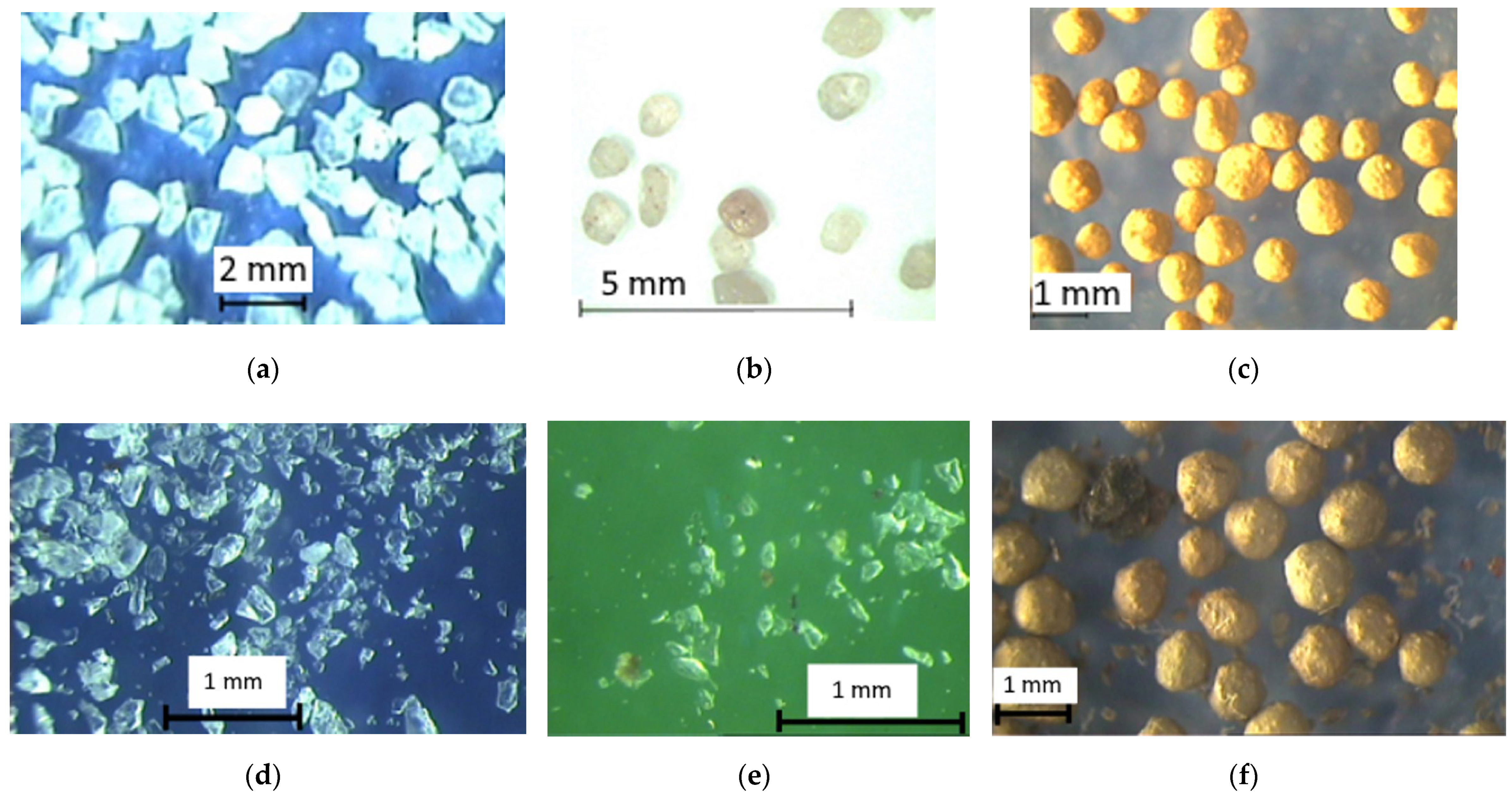
Quartz sand of artificial origin, obtained during grinding of dimension pieces of quartz in crushers; average particle diameter, Di = 1.1 mm (Figure 5a);
River sand of two fractions, with average particle diameters of Di = 0.26 mm and Di = 0.58 mm (Figure 5b);
Proppant with an average particle diameter of Di = 0.88 mm (Figure 5c).
Sampling of the pumped liquid that contained particles of mechanical impurities was carried out after repeated circulation of the hydraulic abrasive mixture through the tested pump stages. Sampling time was calculated with Equation (6):
T = 3.6   ·   N   ·   V t Q z ,
where T—sampling time, s; N—number of working stages through which the abrasive particle would pass, pcs.; Q—test-pump section supply, Q = 6.25 m3/h; z—number of pump stages in the test-pump section, z = 20 pcs; and Vt—test-bench tank volume, Vt = 200 L.
Fluid that contained particulate matter was sampled after circulation of abrasive particles through 20, 40, 60 and 80 pump stages. From the samples obtained, the mechanical impurities were filtered and dried, then analyzed using a microscope.

3. Results

In accordance with the diagram shown in Figure 2, the values of the coefficients of sphericality, Ks, and roundness, Kr, of the particles of the mechanical impurities were determined; the particle size distribution was studied; and the average particle diameter, Df, was determined. The value of the abrasiveness index, AI, was calculated with Equation (3). The results obtained from the studies of water–abrasive mixtures that contained particles of artificial quartz sand and river sand are shown in Figure 6.
Analysis of the obtained graphs showed that the coarse sand particles were subjected to intensive grinding, passing through 40 working stages of the electric centrifugal pump (Figure 6a, position 1, 2), to the average diameter of Df = 0.25…0.3 mm, after which the particle size remained almost unchanged. Particles of fine river sand with an average particle diameter of Di = 0.26 mm (Figure 6a, position 3) were crushed very slightly, to Df = 0.2 mm.
The products of grinding sand of artificial and natural origin have an elongated plate shape (Figure 5a,b,d,e), which determines a decrease in the coefficients of roundness and sphericality of ground particles compared to the particles of the initial model mechanical impurities (Figure 6c,d), causing an increase in their abrasion index (Figure 6b) as they passed through the working stages of the tested pumping section. The minimum increase in the abrasion index as the fluid passed through the working stages of the pumping section in the test was characterized with sand with an initial average particle diameter of Di = 0.26 mm [34].
The obtained conclusions were confirmed via the results of durability tests of a similar pumping section assembled from 20 working stages, 7A-150. In circulation of a hydroabrasive mixture in which river sand with an average particle diameter of Di = 0.58 mm and a concentration of C = 3 g/L was used as mechanical impurities, an increase in the wear of the support washers of the impellers of the stages along the flow from the inlet to the outlet of the pumping section was observed for 4 h. Thus, the support washers of the working stages farther along the flow path were worn out from crushed mechanical impurities more intensely than were the support washers of the stages closest to the flow inlet of the pumping section (Figure 7) [35].
The results of experiments in which water with proppant was used as a hydroabrasive mixture showed that the proppant particles, passing with the flow of liquid through the stages of the tested pumping section, were practically not ground. Upon contact with the metal of the wheels and guide vanes, the upper layers of the proppant granules were removed, while the seal-destruction product, metal and corrosion particles were added to the circulating water–abrasive mixture (Figure 5f) [36,37]. With an increase of more than C = 3 g/L in the proppant concentration in the model hydraulic abrasive mixture, there was almost instantaneous destruction of the support washers of the impellers of the first stages along the flow path and jamming of the rotor of the tested pump section.

4. Discussion

In the Russian and foreign practices of designing ESP installations for the oil industry, the following ways of protecting working stages from hydroabrasive wear are known:
-
Insertion of wear-resistant rings in interstage seals;
-
Application of hard coatings on the surfaces of guide vanes and impellers;
-
Use of stages with enlarged cross-sections of flow channels and protective ribs on the upper disk of the guide apparatus in the cavity under the impeller;
-
Use of stages with holes in the upper disk of the guide apparatus to remove abrasive particles from the cavity under the impeller.
Increased flow through sections of stages (without any change in nominal-stage flow rate) results in decreased hydromechanical mixture velocity, which would determine the decrease in hydroabrasive-wear intensity. However, in this case, the ESP-unit size and cost would increase, and the wear rate of interstage seals would remain at the same level.
The presence of protective ribs on the upper disk of the guide apparatus in the cavity under the impeller changes the character of the eddy-current-formation process. Moving abrasive particles hit the radially located ribs and lose kinetic energy. Destruction of the body of the guide apparatus begins only after the wearing of the protective ribs, which increases its operating time by 30–40%.
However, the obtained positive effect is often insufficient for operation of electric centrifugal pumps in complicated well conditions after hydraulic fracturing.
Placement of holes in the upper disc of the guide apparatus causes reduction in the working stage head due to additional fluid overflow through the holes, which reduces the energy efficiency of ESP operations as a whole.
Today, one of the most cost-effective and efficient ways to protect ESPs from the impact of mechanical impurities is the use of preinjection devices: filters and mechanical-impurity separators.
The analysis of the results of the studies given in this article allowed estimation of the changes in abrasiveness of mechanical impurities pumped with model fluid flow through ESP stages. It was shown that coarse particles of mechanical impurities of natural origin, when in contact with the metal of the working stages, were subjected to intensive grinding to a value of Df = 0.25…0.3 mm, after which the particle size remained practically unchanged; that is, the particles were not ground and their abrasiveness did not increase.
It follows from the above that ESP-unit filters should be selected with a main focus on a cleaning fineness of 0.25…0.3 mm. Particles with an initial size greater than Di = 0.3 mm would be ground, and the destruction products of such particles would be characterized with high abrasiveness. Fine filters undergo intensive colmatation and are characterized with lower dirt capacity and low operating time in downhole conditions.
An increase in the abrasiveness index of mechanical impurities as they pass through working stages causes an increase in the intensity of wear of the wheel-support washers and interstage seals along the flow of the hydraulic abrasive mixture (from the inlet to the outlet of the pumping section).
Uneven hydroabrasive wear of working stages determines the possibility of using electric centrifugal pumps of combined assembly, in which the first stages in the flow direction are of normal design, followed by stages with wear-resistant design [38,39]. The seals in such wear-resistant stages can be made of materials with increased hardness. Use of labyrinth seals, for example, of the type described in the patent is promising [40].
Large abrasive particles formed during destruction of reservoir rocks and removal of loose proppant after hydraulic fracturing during development of wells should be separated from formation fluid using gravity and inertial separators to avoid seizure of the rotors of electric centrifugal pumps [41,42]. At the same time, it is rational to use separators with solid-particle storage containers. This technical solution will remove separated mechanical impurities from the well when the ESP unit is lifted to the daylight surface.
Sequential installation of downhole separators and filters allows creation of cascade systems for cleaning of formation fluid from mechanical impurities, which provides a significant increase in ESP-unit operating time in complicated operating conditions [43]. Use of self-cleaning ESP-unit filters is promising. Examples of such devices are given by the authors of [44,45].

5. Conclusions

Study of the features of the hydroabrasive-wear process of ESP units and development of technical solutions aimed at increasing the operating time of ESP units that pump hydroabrasive mixtures is of current interest for the oil and mechanical-engineering enterprises.
The authors studied issues related to quantitative assessment of changes in abrasiveness of impurity particles contained in water–abrasive mixtures pumped with ESP installations.
It was proven that the intensity of hydroabrasive wear changes depending on the position of the working stage in the pumping section.
The most promising solution for the problem of increasing the operating time of ESP working stages in conditions of intensive hydroabrasive wear is application of downhole filters and separators, as well as improvement of the geometry of contact surfaces and materials of interstage seals.

Author Contributions

Conceptualization, D.S. and A.R.; data curation, D.S. and A.I.; formal analysis, V.Z., I.Z. and A.I.; funding acquisition, D.S. and A.R.; investigation, D.S., I.Z. and V.Z.; methodology, I.Z. and V.Z.; project administration, I.Z. and A.I.; resources, D.S. and A.I.; software, I.Z. and V.Z.; supervision, D.S. and A.I.; validation, A.R., V.Z. and I.Z.; visualization, A.I. and I.Z.; writing—original draft preparation, D.S., A.I. and V.Z.; writing—review and editing, I.Z. and A.R. All authors have read and agreed to the published version of the manuscript.

Funding

This research was carried out with the financial support of the Ministry of Science and Higher Education of the Russian Federation in the framework of the program of activities of the Perm Scientific and Educational Center “Rational Subsoil Use”.

Institutional Review Board Statement

Not applicable.

Informed Consent Statement

Not applicable.

Data Availability Statement

Not applicable.

Conflicts of Interest

The authors declare no conflict of interest.

References

  1. Urazakov, K.R.; Timashev, E.O.; Molchanova, V.A.; Volkov, M.G. Reference Book for Oil Production; Aster Plus: Perm, Russia, 2020; p. 600. [Google Scholar]
  2. Isaev, A.A.; Aliev, M.M.O.; Drozdov, A.N.; Gorbyleva, Y.A.; Nurgalieva, K.S. Improving the efficiency of curved wells’ operation by means of progressive cavity pumps. Energies 2022, 15, 4259. [Google Scholar] [CrossRef]
  3. Lykova, N.A.; Shavaleyeva, A.V.; Shishlyannikov, D.I. Equipment for the protection of electric submersible pump units against scaling and corrosion. Min. Equip. Electromech. 2017, 7, 18–22. [Google Scholar]
  4. Shishlyannikov, D.I.; Shavaleyeva, A.V.; Kulakov, S.V.; Korotkov, Y.G. Improving the efficiency of water treatment in the oil fields through the use of filters produced by «Novomet-Perm» JSC. Oilfield Eng. 2018, 12, 68–73. [Google Scholar] [CrossRef]
  5. Wilson, B.L. Effects of abrasives on electrical submersible pumps. SPE Drill. Eng. 1990, 5, 171–175. [Google Scholar] [CrossRef]
  6. Ovchinnikov, N.P.; Portnyagina, V.V.; Dambuev, B.I. Specifying the technical state limit value of the pump pulp without disassembling. J. Min. Inst. 2020, 241, 53–57. [Google Scholar] [CrossRef]
  7. Ostrovskiy, V.G.; Perel’man, M.O.; Peshcherenko, S.N. Mechanism of hydro-abrasive wear of oil pumps’ stages. Drill. Oil 2012, 10, 36–38. [Google Scholar]
  8. Sun, Z.; Yu, J.; Tang, F. The influence of bulb position on hydraulic performance of submersible tubular pump device. J. Mar. Sci. Eng. 2021, 9, 831. [Google Scholar] [CrossRef]
  9. Sidorkin, D.I.; Kupavykh, K.S. Justification on choosing screw pumping units as energy efficient artificial lift technology. Energy 2021, 64, 143–151. [Google Scholar] [CrossRef]
  10. Rogachev, M.K.; Aleksandrov, A.N. Justification of a comprehensive technology for preventing the formation of asphalt-resin-paraffin deposits during the production of highlyparaffinic oil by electric submersible pumps from multiformation deposits. J. Min. Inst. 2021, 250, 596–605. [Google Scholar] [CrossRef]
  11. Skrebnev, V.I.; Serjan, S.L.; Kalugina, E.V. Research of resistance to water-jet wear of plastic and steel pipes. Assessment of the main parameters that affect the wear rate of hydraulic transport systems. Plasticheskie Massy 2020, 9–10, 40–44. [Google Scholar] [CrossRef]
  12. Koteleva, N.; Valnev, V.; Frenkel, I. Investigation of the effectiveness of an augmented reality and a dynamic simulation system collaboration in oil pump maintenance. Appl. Sci. 2022, 12, 350. [Google Scholar] [CrossRef]
  13. Deshmukh, D.; Siddique, M.H.; Samad, A. Surface roughness effect on performance of an electric submersible pump. Am. Soc. Mech. Eng. 2017, 1, 134225. [Google Scholar] [CrossRef]
  14. Atroshchenko, V.A.; Alexandrov, V.I. Increasing the efficiency of the transport pipelines of the stowing complex with the application of a polyurethane coating. Min. Inf. Analyt. Bull. 2022, 10, 25–38. [Google Scholar] [CrossRef]
  15. Ostrovskiy, V.G.; Peshcherenko, S.N. Bench modeling of corrosion-abrasive destruction of oil pump guide apparatus. Sci. Res. Innov. 2010, 4, 86–88. [Google Scholar]
  16. Ostrovsky, V.G.; Zverev, V.Y. Stand for testing stages of electric-centrifugal oilfield pumps. News High. Inst. Min. J. 2017, 7, 102–106. [Google Scholar] [CrossRef]
  17. Zhivotovsky, L.S.; Smoilovskaya, L.A. Technical Mechanics of Hydraulic Mixtures and Soil Pumps; Mashinostroenie: Moscow, Russia, 1986; p. 224. [Google Scholar]
  18. Ostrovskiy, V.G.; Peshcherenko, S.N. Effect of leakage on the performance and reliability of oil pumps. Sci. Res. Innov. 2011, 5, 171–176. [Google Scholar]
  19. Bai, C.; Zheng, D.; Hure, R.; Saleh, R.; Carvajal, N.; Morrison, G. The impact of journal bearing wear on an electric submersible pump in two-phase and three-phase flow. J. Tribol. 2019, 141, 051702. [Google Scholar] [CrossRef]
  20. Patil, A.; Kasprzyk, M.; Delgado, A.; Morrison, G. Effect of leakage flow path wear on axial thrust in downhole electrical submersible pump unit. J. Fluids Eng. 2020, 142, 051202. [Google Scholar] [CrossRef]
  21. Yang, P.; Chen, J.; Zhang, H.; Li, S. A fault identification method for electric submersible pumps based on DAE-SVM. Shock. Vib. 2022, 2022, 5868630. [Google Scholar] [CrossRef]
  22. Yakovlev, A.L.; Savenok, O.V. Analysis of the effectiveness of the equipment used and the possible causes of failure in intensification of oil production in the fields of the Krasnodar territory. Min. Inf. Analyt. Bull. 2016, 5, 149–163. [Google Scholar]
  23. Ovchinnikov, N.P. Mechanized complex of mine water purification from large mechanical impurities. IOP Conf. Ser. Earth Environ. Sci. 2021, 839, 042039. [Google Scholar] [CrossRef]
  24. Smirnov, N.I. Wear features of high-speed submersible pumps for oil production. Neftyanoe Khozyaystvo—Oil Indust. 2021, 1, 62–65. [Google Scholar] [CrossRef]
  25. Bolobov, V.I.; Plaschinsky, V.A. Influence of impact duration on fracture efficiency in rocks and on plastic deformation of metals. Min. Inf. Analyt. Bull. 2022, 3, 78–96. [Google Scholar] [CrossRef]
  26. Lavrenko, S.A.; Klushnik, I.D.; Iarmolenko, V.A. Test results for hydraulic drives of sucker-rod pumping units. ARPN J. Eng. App. Sci. 2019, 16, 2881–2885. [Google Scholar]
  27. Lykova, N.A. Protection of ESP against clogging: A complex analysis. Eng. Pract. 2016, 4, 44–50. [Google Scholar]
  28. Fecarotta, O.; Martino, R.; Morani, M.C. Wastewater pump control under mechanical wear. Water 2019, 11, 1210. [Google Scholar] [CrossRef]
  29. Maksarov, V.V.; Keksin, A.I.; Filipenko, I.A. Influence of magnetic-abrasive processing on roughness of flat products made of amts grade aluminum alloy. Tsvetnye Met. 2022, 7, 82–87. [Google Scholar] [CrossRef]
  30. Adams, D.L. Parameters to analyze when determining abrasive wear in an electrical submersible pump system. In SPE Bergen One Day Seminar; OnePetro: Bergen, Norway, 2015; pp. 496–502. [Google Scholar] [CrossRef]
  31. Bolobov, V.I.; Akhmerov, E.V.; Rakitin, I.V. Influence of rock type on regularities of excavator bucket tooth crown wear. Min. Inf. Analyt. Bull. 2022, 6, 189–204. [Google Scholar] [CrossRef]
  32. Drozdov, A.N.; Verbitsky, V.S.; Igrevsky, L.V.; Dengaev, A.V.; Nikolaev, D.A.; Goridko, K.A. Method of rating serial submersible pumping equipment based on bench test results. Neftyanoe Khozyaystvo—Oil Indust. 2021, 6, 84–88. [Google Scholar] [CrossRef]
  33. Atroshchenko, V.A.; Avksentiev, S.Y.; Makharatkin, P.N.; Trufanova, I.S. Experimental hydrotransportation unit for testing material resistance of pipelines and parts of dredging pumps to hydro-abrasive wear. Obogashchenie Rud 2021, 3, 39–45. [Google Scholar] [CrossRef]
  34. de Bonilla, S.G.D.; Chen, H.-Y. Analytical and numerical studies of sand erosion in electrical submersible pump (ESP) systems. In Proceedings of the Unconventional Resources Technology Conference, Denver, CO, USA, 22–24 July 2019; p. 5455. [Google Scholar] [CrossRef]
  35. Ovchinnikov, N.P. One of the ways to increase the durability of the sectional pump balancing ring. J. Min. Inst. 2020, 248, 312–318. [Google Scholar] [CrossRef]
  36. Ponticelli, G.S.; Tagliaferri, F.; Venettacci, S.; Horn, M.; Giannini, O.; Guarino, S. Re-engineering of an impeller for submersible electric pump to be produced by selective laser melting. Appl. Sci. 2021, 11, 7375. [Google Scholar] [CrossRef]
  37. Kou, B.; Li, Z.; Zhang, Z.; Li, R. Friction and wear properties of hydraulic components with ceramic/steel-to-steel pairs. J. Mech. Sci. Tech. 2021, 35, 3375–3388. [Google Scholar] [CrossRef]
  38. Vasilyeva, M.A. Substantiation of parametric and standard series magnetic peristaltic pumping units. Min. Inf. Analyt. Bull. 2022, 12, 70–86. [Google Scholar] [CrossRef]
  39. Xiao, J.J.; Lastra, R.A.; Roth, B.A.; Aramco, S.; Lee, W. Material overview for electrical submersible pumps: Part I—Metallic and ceramic materials. SPE Prod. Operat. 2020, 35, 1–8. [Google Scholar] [CrossRef]
  40. Ostrovsky, V.G.; Pescherenko, M.P.; Pescherenko, S.N. Multistage Submersible Centrifugal Pump Stage. Patent RU 2454657, 2012. [Google Scholar]
  41. Lykova, N.A. Equipment for ESP operation in conditions of intensive overflow of mechanical impurities. Eng. Pract. 2017, 3, 58–62. [Google Scholar]
  42. Leon, J.L.V.; Hill, C.R. Extended-life ESP reliably accommodates wide, abrasive production range in remote brownfield. World Oil 2021, 242, 23–27. [Google Scholar]
  43. Nikolaichuk, L.; Sinkov, L.; Malisheva, A. Analysis of the problems and development prospects of the oil refining industry of Russia. J. Bus. Retail Manag. Res. 2017, 11, 177–183. [Google Scholar] [CrossRef]
  44. Shishlyannikov, D.I.; Shavaleeva, A.V.; Korotkov, Y.G.; Perelman, M.O.; Poshvin, E.V. Slotted Filter. Patent RU 2709580, 18 December 2019. [Google Scholar]
  45. Shishlyannikov, D.I.; Shavaleeva, A.V.; Korotkov, Y.G.; Perelman, M.O.; Poshvin, E.V. Slotted Filter. Patent RU 2715774, 3 March 2020. [Google Scholar]
Figure 1. Hydroabrasive wear of the guide vanes (a) (the arrow points to areas of local hydroabrasive wear of the ESP guide apparatus, the dotted line shows its original cross-sectional shape) and the consequences of cutting the housings of electric submersible pumps (b,c) (arrows show the consequences of hydro-abrasion—cutting of the ESP housing).
Applsci 13 01885 g001
Figure 2. Diagram for visual determination of the values of the coefficients of roundness, Kr, and sphericality, Ks, of particulate matter of mechanical impurities.
Applsci 13 01885 g002
Figure 3. Test bench for operating stages of electric centrifugal pumps.
Applsci 13 01885 g003
Figure 4. Test hydraulic diagram of the bench for testing the operating stages of electric centrifugal pumps.
Applsci 13 01885 g004
Figure 5. Particle shape and granulometric composition of model mechanical impurities: (ac)—initial shape and composition; (df) after passing through 80 working stages, 7A-150, of the tested section of the electric centrifugal pump; (a,d) particles of artificial quartz sand; (b,e) particles of river sand; and (c,e) proppant.
Applsci 13 01885 g005
Figure 6. Changes in the average diameter (a), abrasiveness index (b), roundness coefficient (c) and sphericity coefficient (d) of sand particles contained in the hydroabrasive mixture during passing through the pump stages of the electric centrifugal pump: 1—quartz sand of artificial origin, Di = 1.1 mm; 2—river sand, Di = 0.58 mm; 3—river sand, D = 0.26 mm.
Applsci 13 01885 g006
Figure 7. Change in the wear value, S, of wheel thrust washers depending on the location of the stage of the pumping section in the direction of the water–abrasive mixture flow.
Applsci 13 01885 g007
Table 1. Program of experimental research to assess changes in abrasiveness of solid particles in hydromechanical mixtures pumped with ESPs.
Stage NumberName of Research StageContents of the Research Stage
1Setting the Research GoalEvaluation of changes in abrasiveness of solids in hydraulic mixtures pumped with ESPs.
2Setting the Research Problem
Development of the main provisions of the experimental research methodology;
Development of a laboratory bench;
Selection of the types and concentrations of model mechanical impurities;
Selection of the method for assessing changes in the abrasiveness of solid particles in the model hydromixture pumped with an ESP.
3Research Execution; Data Collection and ProcessingEvaluation of the initial parameters of the model mechanical impurities: average diameter, abrasiveness index, coefficient of roundness and coefficient of sphericity;
preparation of a model hydroabrasive mixture; filling the hydraulic system of the bench;
sampling of mechanical impurities after their passing through 20, 40, 60 and 80 working stages of the bench pumping section;
filtration of mechanical impurities; drying of impurities; and analysis of the obtained data.
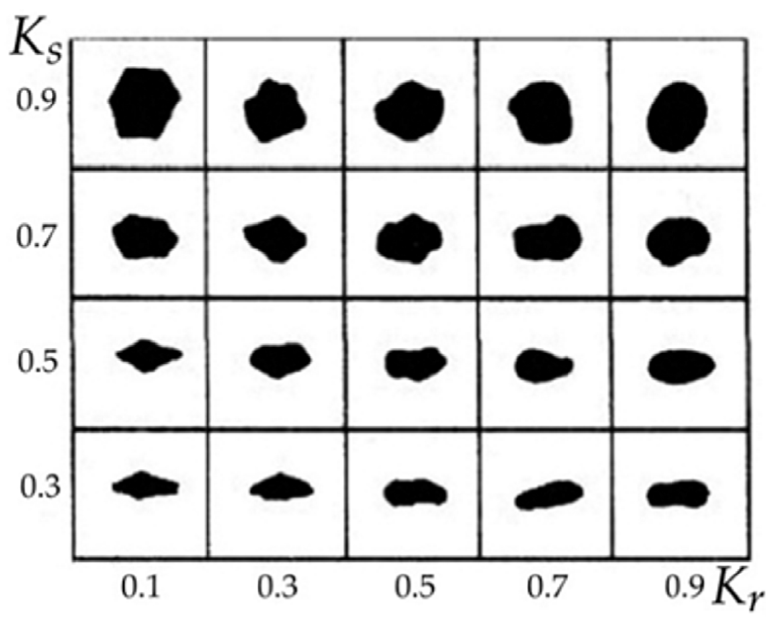
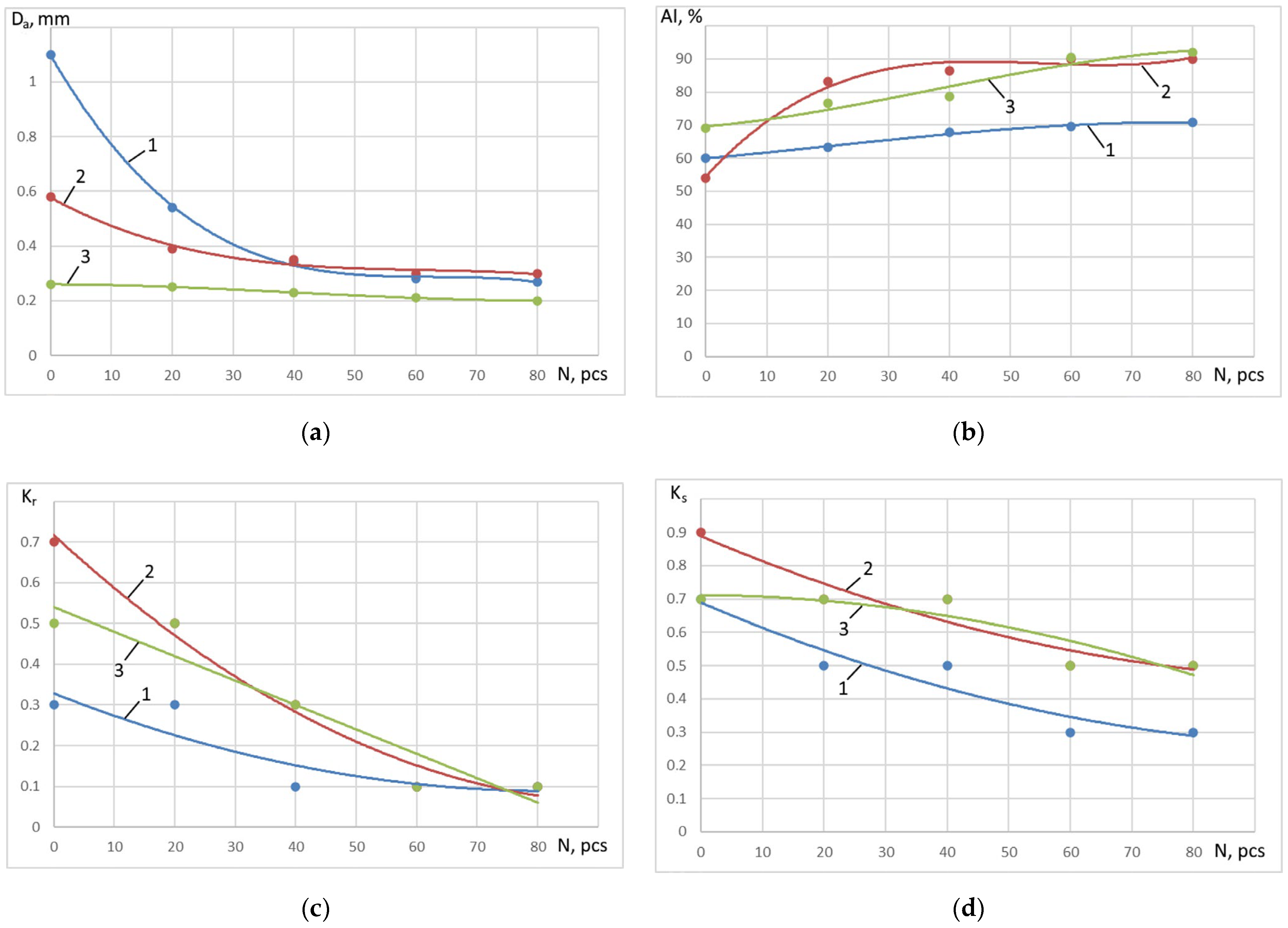
4Research ResultsConstruction of dependencies:
changes in the average diameter of mechanical impurities from the number of working stages, Df;
changes in the index of abrasiveness of mechanical impurities on the number of working stages, AI;
changes in the coefficient of roundness of particles of mechanical impurities from the number of working stages, Kr;
and changes in the coefficient of sphericity of particles of mechanical impurities from the number of working stages, KS.
Disclaimer/Publisher’s Note: The statements, opinions and data contained in all publications are solely those of the individual author(s) and contributor(s) and not of MDPI and/or the editor(s). MDPI and/or the editor(s) disclaim responsibility for any injury to people or property resulting from any ideas, methods, instructions or products referred to in the content.

