Article

Identification Procedure for Design Optimization of Gravitational Electromagnetic Energy Harvesters

Department of Mechanical and Aerospace Engineering, Politecnico di Torino, 10129 Turin, Italy
*
Authors to whom correspondence should be addressed.
Appl. Sci. 2023, 13(4), 2736; https://doi.org/10.3390/app13042736
Submission received: 3 February 2023 / Revised: 15 February 2023 / Accepted: 17 February 2023 / Published: 20 February 2023
(This article belongs to the Special Issue State-of-the-Art in Energy Harvesting for IoT and WSN)

Abstract

:

Featured Application

Gravitational energy harvesters can be destined to freight railcars monitoring applications as a power supply for sensorized wireless nodes, thus creating Autonomous Internet of Things (AIoT) devices.

Abstract

Energy harvesting is a promising technique for supplying low-power devices as an alternative to conventional batteries. Energy harvesters can be integrated into Autonomous Internet of Things (AIoT) systems to create a wireless network of sensor nodes for real-time monitoring of assets. This paper shows a design and optimization methodology for gravitational vibration-based electromagnetic energy harvesters (GVEHs) of different sizes considering the design constraints of its real application. The configuration, analytical model, and electro-mechanical coupling of these devices are described in detail. A numerical model is developed in the Ansys Maxwell FEM environment to derive the non-linear stiffness and damping of the asymmetric magnetic suspension. Experimental laboratory tests on three harvester prototypes are compared to numerical results of dynamic simulations in MATLAB/Simulink for the validation of the proposed model through error estimation. The fully-parametric validated model is used to perform sensitivity analyses on the device’s mechanical characteristics of natural frequency and magnet equilibrium position by varying the fixed and moving magnets dimensions. The set of magnets composing the magnetic spring is chosen complying with the application design constraints of size and resonance frequency tuning. Coil parameters of length and number of turns are optimized for maximum output power generation. The optimized device simulated performances are compared to other devices in the literature in terms of NPD, a significant index that evaluates power density under different excitation amplitudes. The optimized harvester presents the highest NPD value of 2.61, achieving an improvement of 52% with respect to the best harvester amongst the three tested prototypes.

1. Introduction

Energy harvesting is an emerging solution for the conversion of ambient energy into electric energy. The recent trend in the research field is the use of energy harvesters to power Internet of Things (IoT) devices, in particular wireless sensor nodes (WSN). The main goal is finding an alternative sustainable, reliable and cost-effective power source to replace batteries for remote monitoring applications [1]. These devices can be used in different sectors, from industrial to transportation, healthcare and smart homes [2]. Energy harvesters are classified by the type of energy source (thermal, wind, solar, waves, vibrations) and the conversion methodologies. The amount of generated power is usually from tens of micro-Watt to milli-Watt, depending on the conversion methodology, efficiency, and environmental conditions [3]. In the industrial and vehicle fields the most promising energy harvesting methodology is the exploitation of mechanical energy coming from ambient vibrations. These can be easily harvested as kinetic energy and converted into electric power [4]. Vibrational electromagnetic energy harvesters (VEHs) can be classified by the transduction mechanism in piezoelectric (refs. [5,6,7]), electromagnetic, and triboelectric harvesters [8]. The electromagnetic energy harvester working principle relies on Faraday’s law of voltage induction thanks to a variable magnetic flux generated by the relative motion between a magnet and a coil [9]. The most common configurations for electromagnetic energy harvesters are spring-mass-damper 1DOF (one degree-of-freedom) systems. The maximum power conversion happens at the resonance frequency of the system. Consequently, one of the relevant design issues is the correct tuning of the resonance frequency with the fundamental excitation frequencies of the ambient vibrations of the specific monitored system on which the harvester is installed. Linear generators using traditional mechanical springs show limited bandwidths for effective power generation, hence solutions to improve the conversion efficiency should be studied [10,11]. An effective solution can be the introduction of non-linearities in the system dynamics, more specifically using non-linear magnetic springs. Magnetic suspensions have significant advantages with respect to the use of mechanical springs. The absence of mechanical systems leads to an improvement in durability and maintenance reduction. Magnetic springs show resonance conditions at a low-frequency range, thus being compatible with harvesting applications in industrial vehicles [4,12].
In recent years, many researchers have studied different configurations of magnetically-suspended VEHs (MVEHs) to maximize generated power. Foisal et al. [13] have studied a multi-frequency MVEH consisting of an array of four generators to enhance power density and broaden the frequency band. Zhao et al. [14] developed a small-sized MVEH to harvest human body mechanical motion with an optimized design to maximize output power. Cronin et al. [15] investigated the exploitation of in-plane vibrations realizing two planar MVEHs to easily integrate printed circuit boards in the design. Vidal et al. [16] designed an MVEH with a self-adaptive structure, capable of coil switching with active feedback control to improve conversion efficiency at different excitation frequencies and amplitudes. Hossain et al. [17] developed a device capable of stiffness tuning using magnetic rotors. Our research group has carried out previous works regarding MVEHs applications in the railway and biomechanical fields [18,19]. Both numerical and experimental approaches were adopted to investigate the dynamics of the magnetic suspension and its conversion efficiency [20,21]. The peculiarity of our devices is the use of an asymmetric magnetic suspension with only one fixed magnet at the bottom. These devices are called gravitational vibrational energy harvesters (GVEHs) since they exploit gravity actions as the restoring force due to the absence of the top fixed magnet. This configuration shows a non-linear “softening” behavior that reduces the system’s natural frequency as the excitation amplitude increases. The realization of a two-degrees-of-freedom system has led to a performance improvement in terms of frequency broadening and power generation [22].
The purpose of this study is to provide a design and optimization procedure for GVEHs, performing sensitivity analyses based on both numerical simulations and experimental validation on multi-scaled prototypes. The purpose of the proposed procedure is to design the best-performing device suited for a specific application, having compatible size and resonance conditions tuned to the fundamental frequencies range of the random vibrations carrying the highest energy content. Some authors have investigated the design strategies for MVEHs with symmetric springs through numerical simulations only without experimental comparison on real prototypes [23]. Others performed design optimization of MVEHs both experimentally and numerically but do not consider specific application constraints for the design process, [24]. Most of the authors focus only on the maximization of the prototype output power in laboratory tests but do not follow a proper design approach since the real application constraints are not considered [25,26]. The magnet’s dimensions should not be chosen based only on power criterion, as they affect the dynamics in terms of resonance frequency, equilibrium position and overall system size. These factors are often design constraints in the real application system on which the VEH should be installed, having its own fundamental frequencies during vibration and installation limits. A numerical modeling technique for GVEHs is proposed using a combination of Ansys Maxwell FEM environment and MATLAB/Simulink. The numerical model is necessary to derive non-linear stiffness and damping characteristics and to simulate the system’s dynamic behavior. The proposed modeling approach is applied to three GVEH prototypes having different sizes. Numerical results of dynamic simulations are compared to experimental data from laboratory tests on the prototypes for validation of the modeling technique. The validated model is then used to perform sensitivity analyses of the system resonance frequency and equilibrium position by varying both fixed and moving magnet dimensions. These analyses allow us to evaluate the two magnet volumes of the asymmetric magnetic suspension that comply with the design constraints of the destined application and generate the maximum possible power. Coil length and the number of turns optimization is the final step of the design process for maximizing the device performance.
Section 2 shows the materials and methods used in the paper. Firstly, the configurations of the tested harvesters and their main design parameters are displayed. Secondly, the analytical model of the GVEH is described along with its equation of motion and electro-mechanical coupling of the transducing mechanism. Then, the derivation method of the stiffness and damping non-linear characteristics from Ansys Maxwell numerical simulations is presented. Moreover, it features a description of the experimental apparatus used for laboratory tests on prototypes in order to validate the numerical model. Section 3 reports and compares the results of numerical dynamic simulations in MATLAB/Simulink and experimental tests on prototypes. Consequently, the validated model is used to perform the sensitivity analyses for the optimization procedure of the set of magnets and the coil parameters. The simulated performances and characteristics of the resulting optimized device are compared to the three tested prototypes and other similar devices in the literature. Section 4 reports final conclusions on the proposed optimization procedure and future works.

2. Materials and Methods

The devices analyzed in this work are cylindrical 1DOF GVEHs. The main components of these systems include a suspended moving magnet, a fixed magnet at the bottom and coils wrapped around a tube. Three different configurations are studied, varying the magnets, the tube dimensions, the presence of the internal guide, the number of turns, and the axial location of the coils. For sake of simplicity, the configurations are referred to as EH1, EH2, and EH3 with increasing sizes. A schematic representation of the three energy harvesters can be seen in Figure 1. The values of the highlighted main dimensions are reported in Table 1. These devices have magnets sizes that are chosen to tune the resonance frequency in the range of 3–6 Hz. The configurations have different stiffness tuning and global dimensions, in order to experimentally evaluate different dynamics and power generations, thus having a deeper knowledge of the design optimization procedure. To achieve this purpose, the configurations present moving and fixed magnets with different dimensions, thus changing the system resonance frequency and the magnetic flux linkage with the coils. All the magnets in the three configurations are made of NdFeB42. The dimensions of moving and fixed magnets for all configurations are reported in Table 2.
Different tube lengths are adopted in order to enable adequate strokes compatible with the specific configuration stiffness. Each device has coils with different dimensions, number of turns, and resistance, but has the same material (enameled copper) and the same cross-section diameter of 0.1 mm. The coils in each configuration are placed along the tube at different heights to find the axial location of the coil that optimizes the generated power. This phenomenon is linked to the variation of the magnetic flux linkage of the coils during the motion of the suspended mass. Further details on this behavior can be found in Section 2.1. Table 3 shows the main characteristics of the coils for EH1, EH2, and EH3.

2.1. Analytical Model

The analytical model of the generator consists of a 1DOF non-linear mass-spring-damper system [27]. The seismic mass m of the system is the moving magnet which is suspended thanks to the repulsive force of the fixed magnet at the bottom. The stiffness k is related to the magnetic suspension. The damping characteristic derives from two components: mechanical due to the viscous action of the air and friction ( c v i s ), electromagnetic due to the induction of parasitic currents in the coils ( c e m ) [28]. External inputs on the system generate out-of-phase oscillation motions of the moving magnet. The transducing mechanism consists of the time variation of the magnetic flux linkage of the coils due to the relative motion of the mass inside the tube, thus inducing an electromotive force. A representation of the system analytical model is shown in Figure 2a. The equation of motion of the system (1) is a second-order differential equation expressed in the variable z, which is the relative motion coordinate of the moving magnet with origin in the equilibrium position [20].
z ¨ = c t o t ( z ) m z ˙ k ( z ) m z + Y 0 sin ( Ω t )
where:
  • z is the relative motion coordinate of the moving magnet;
  • m is the seismic mass of the moving magnet;
  • c t o t is the sum of viscous damping c v i s and electromagnetic damping c e m ;
  • k is the non-linear stiffness of the magnetic spring;
  • Y 0 is the external acceleration amplitude of sinusoidal input;
  • Ω is the pulsation of the external excitation.
The device configuration is characterized by an electro-mechanical coupling. The induced electromotive force and the generated power depend on the moving magnet speed and displacement. Therefore, the electromagnetic subsystem needs to be studied separately and coupled with the mechanical subsystem to correctly analyze the system behavior. The electromagnetic subsystem is modeled as a purely resistive circuit where the harvester is the AC source, having an internal resistance R c o i l , connected to the external resistance R l o a d that needs to be properly optimized for maximum power generation in each configuration. The scheme of the electromagnetic circuit of the harvester is reported in Figure 2b.
The electromagnetic coupling coefficient k e m ( z ) derives from the variation of the magnetic flux during the moving magnet oscillation (2). The coefficient directly links the voltage to the moving magnet speed (3) and defines the electromagnetic damping force acting on the moving mass (4)–(5).
k e m ( z ) = d Φ d z
V e h = d Φ d t = d Φ d z d z d t = k e m z ˙ ( t )
F e m = k e m ( z ) × i ( t ) = k e m 2 ( z ) × z ˙ ( t ) R c o i l + R l o a d = c e m ( z ) × z ˙ ( t )
c e m ( z ) = k e m 2 ( z ) R c o i l + R l o a d
Coils dimensions and location along the tube need to be properly designed in order to extract the maximum amount of power from the system. Coil resistance is depending on the cross-section area and material of the wires (copper resistivity ρ C u ), number of turns, and mean diameter of the coil (6).
R c o i l = 4 ρ C u d w i r e 2 × d c o i l , m e a n × N t u r n s
An increasing number of turns results in a higher coupling coefficient but also greater damping, thus modifying the moving magnet speed and the variation of flux linkage in time. The coil axial length and location along the tube play a critical role in power generation because they affect the flux linkage variation during the magnet oscillation. The optimum load resistance value depends not only on the coil resistance but also on the electromagnetic coupling coefficient and viscous damping, hence on the moving magnet dimensions [29].
R l o a d , o p t = R c o i l + k e m 2 c v i s
Equations (1)–(5) are implemented in a MATLAB/Simulink model for dynamic simulations of the system to obtain the moving magnet position, speed, acceleration, induced voltage, current, and generated power on the load for each time step. The Simulink block scheme is shown in Figure 3 and needs the stiffness and damping characteristics to be defined for each harvester configuration. Ansys Maxwell software for FEM analyses is essential for this study as it allows us to numerically evaluate the characteristics mentioned above. The stiffness and damping data obtained from Ansys simulations are thus inserted in the Simulink model as 1D Look-up Table blocks.

2.2. Numerical Model

Ansys Maxwell software allows us to perform magnetostatic and transient electromagnetic simulations to evaluate the force of the magnetic springs and the magnetic flux linkage through the coils. Models for the three harvesters are built in 2D cylindrical coordinates given the axisymmetry of the configurations. Figure 4a,b show the magnetic field resulting from the magnetostatic analysis (a) and the flux linkage from the transient electromagnetic analysis (b) for EH3 configuration with the moving magnet in its equilibrium position. The magnitude of the magnetic repulsive force and of the magnetic flux linkage both depend on the position of the moving magnet inside the tube. This dependence introduces non-linearities in both stiffness and damping characteristics, as the moving magnet position varies in time under external excitation. A numerical approach is necessary to derive the system characteristics which determine the dynamics behavior of the energy harvesters.
The main mechanical characteristics of the harvesters are the stiffness of the magnetic spring k and the viscous damping c v i s . Magnetostatic analyses in Ansys Maxwell need to be performed for the definition of the stiffness characteristic. The moving magnet position is swept from the bottom of the tube, ideally touching the fixed magnet, to the top. The simulations enable the evaluation of the distribution of magnetic field vectors created by the two opposing magnets for each step of the moving magnet position, as Figure 4 shows.
For every position of the moving magnet, Ansys Maxwell computes the corresponding repulsive force between the two magnets of the system F m a g ( z ) . As stated in [30], the magnetic force acting between two magnetic dipoles having the same magnetic moment and their axes aligned is proportional to 1 / z 4 . Even though the magnets in the three configurations have significantly different magnetic moments, the proposed function fits the simulation data quite precisely. The expression of the function is the following:
F m a g , f i t ( z ) = p 1 z 4 + q 1 z 3 + q 2 z 2 + q 3 z + q 4
The coefficients are determined in the MATLAB environment for each harvester configuration. Figure 5 shows the plots of the magnetic force fitting curves for EH1, EH2, and EH3 compared to the simulation data. The stiffness characteristic can be easily obtained by deriving again the magnetic force fitting function with respect to z.
k ( z ) = d F m a g , f i t ( z ) d z
The computation of the magnet equilibrium position can be done by finding the coordinate z 0 at which the magnetic force function equals the moving magnet weight.
F m a g , f i t ( z 0 ) = F 0 = m g
The system can be linearized by evaluating the stiffness in the equilibrium position and the corresponding linear resonance frequency.
f n = 1 2 π k ( z 0 ) m = 1 2 π 2 g z 0
Table 4 summarizes the main results of static simulations on the three harvesters.
Another mechanical characteristic of the system is the viscous damping due to air action and surface friction of the moving magnet. The damping coefficient is considered a constant and is defined through experimental tests on the devices. Free-fall tests of the moving magnet are carried out on the experimental apparatus (described in Section 2.3). The harvester time response of output voltage signal is processed to extract the damping value. As can be seen in Figure 6 the peaks of the output signal are interpolated with an exponential function of time:
y = a e b t
where b is the exponential decay constant that allows us to evaluate the viscous damping [31].
c v i s = 2 m b
Table 5 shows the obtained values of viscous damping for the three configurations and the corresponding damping factor computed following this formula:
ζ v i s = c v i s c v i s , c r i t = c v i s 2 k 0 m
The results show that EH1 and EH3 configurations, both having an internal guide, have an almost identical viscous damping factor that is slightly higher than EH2. Therefore, the internal guide may increase the mechanical damping factor. However, the internal guide may be useful in real applications where the excitations are not perfectly aligned with the moving magnet axis, allowing us to reduce undesired transversal motions and rotations that may arise.
The harvester electromechanical coupling depends on two key characteristics, which are the electromagnetic damping and coupling coefficient. These characteristics are non-linear since they depend on the time variation of the magnetic flux linkage across the coils during the magnet oscillation. The induced electromotive force is directly dependent on the moving magnet speed, hence the generated power. Transient simulations in Ansys Maxwell are performed for the evaluation of the magnetic flux linkage across the harvester windings. The output of the numerical simulations is the curves of the magnetic flux for different positions of the moving magnet inside the tube, as can be seen in Figure 4b. Each simulation is carried out by connecting only one coil at a time and for all three configurations. Afterward, the electromagnetic coupling coefficient and damping can be easily determined following Equations (2) and (5). The obtained curves are reported in Figure 7 for each harvester.

2.3. Experimental Setup

The experimental tests on the harvester prototypes, whose results are reported and discussed in Section 3.1, are performed on a dynamic workbench for evaluation of their performances and for load optimization. The experimental setup and its logic flow are schematized in Figure 8. A picture of the real experimental setup is shown in Figure 9.
The energy harvester prototypes are mounted on the moving base of a shaker (TIRA TV51120) that imposes the ideal sinusoidal acceleration input. The shaker is supplied by a DAQ with LabView software (National Instruments, Austin, TX, USA) and an amplifier (BAA 500) with variable gain control (TIRA GmbH, Schalkau, Germany). The closed-loop feedback signal for the computation of the gain is performed by a piezoelectric accelerometer (PCB Piezotronics, Depew, NY, USA), which is fixed on the prototype base. The energy harvester output voltage signal is measured across a resistive load. The resistance can be freely changed during load tests for optimization of the generated power.

3. Results and Discussions

The purpose of this work is to create a parametrized model for the three different-scaled harvesters in order to study the influence of the magnetic suspensions and the coils on the dynamics and performance via sensitivity analyses. The model needs to be validated by comparison with the experimental results of the prototypes on the dynamic workbench.

3.1. Experimental and Numerical Results

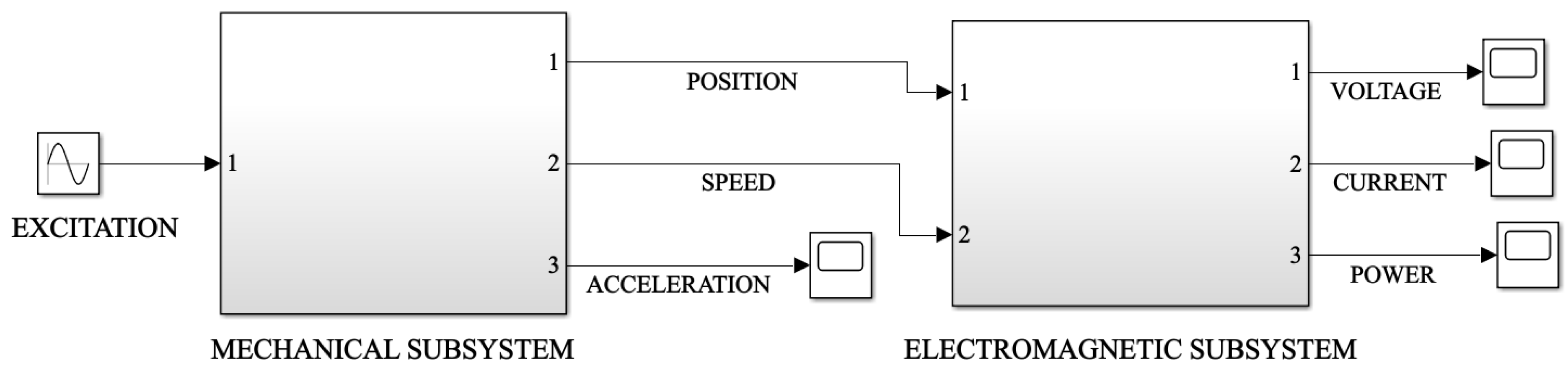
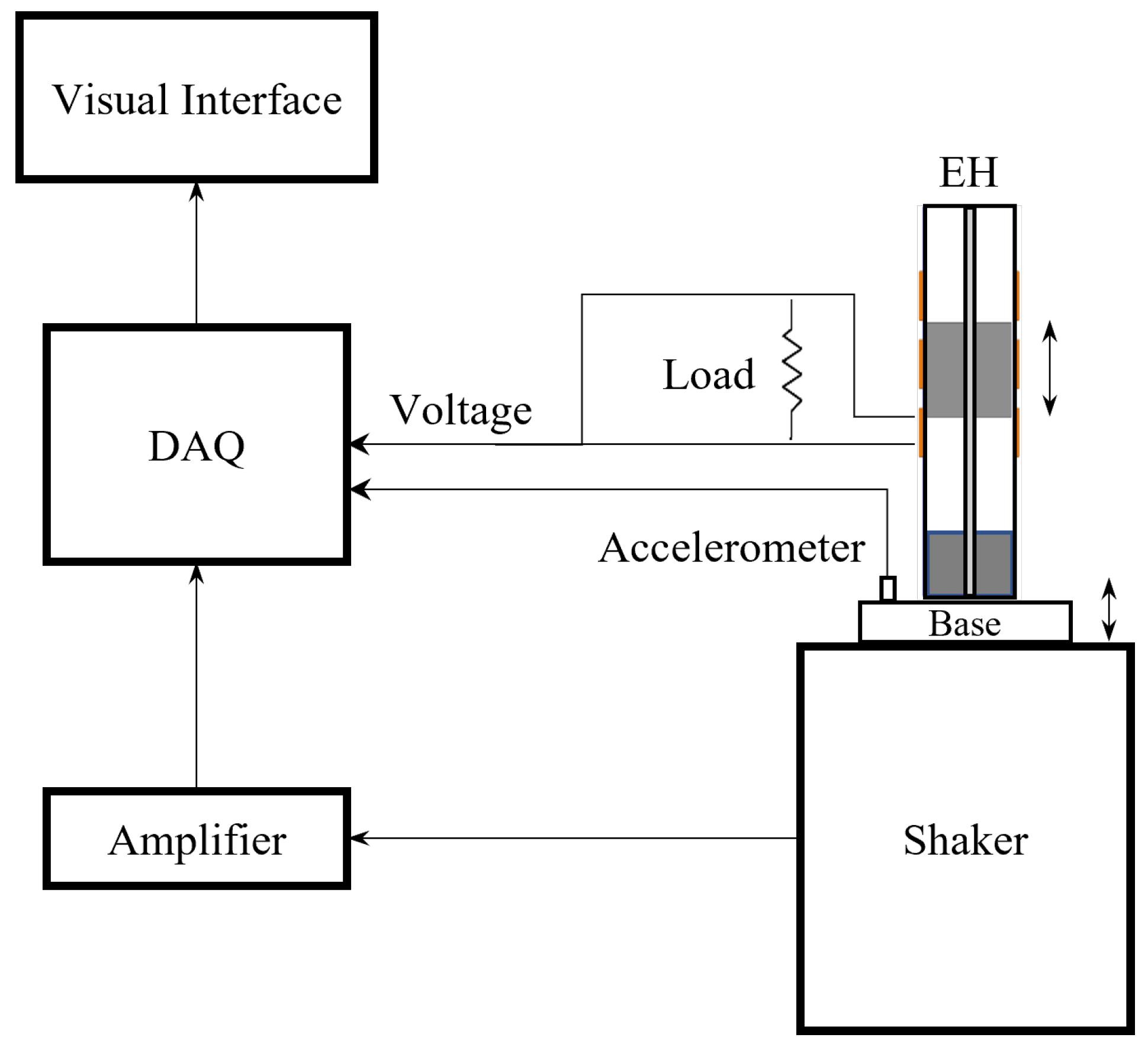
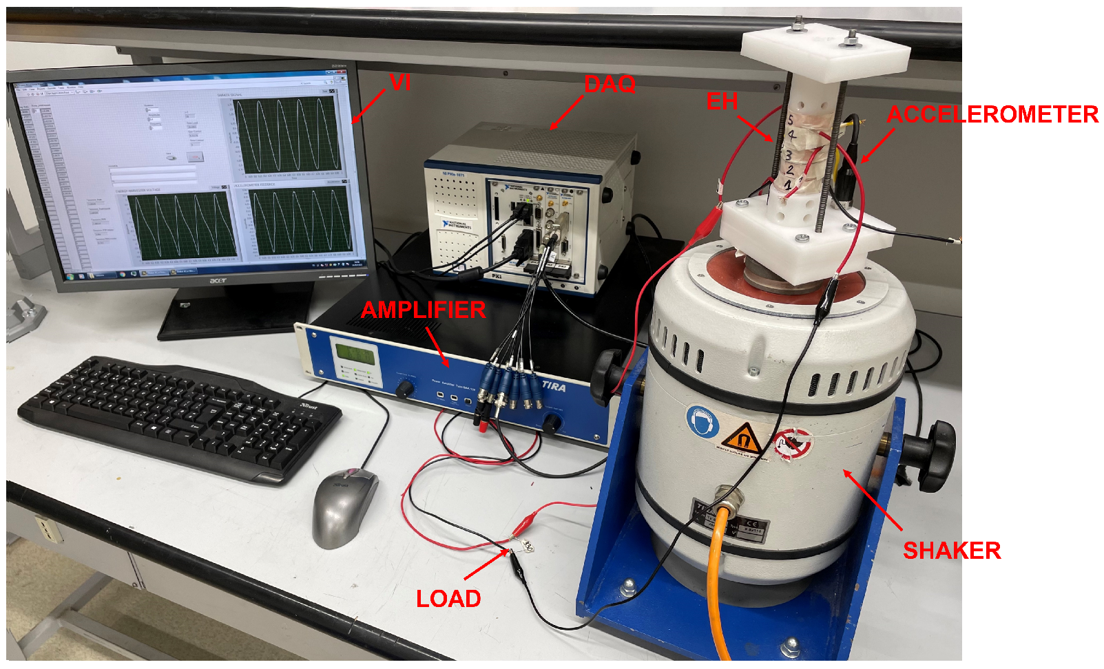
The dynamic behavior of the harvester system can be studied through the evaluation of the Frequency Response Functions (FRFs). These curves show the harvester performances when different excitation amplitudes and frequencies are applied to the system. The non-linear softening behavior of the device can be highlighted by analyzing the FRFs. The non-linearities cause the resonance frequency of the system to decrease as the external excitation amplitude increases. The FRFs evaluation is performed both numerically and experimentally for model validation. FRFs are reported in terms of the root mean square value of the generated power on the load. Numerical dynamic simulations are performed in MATLAB/Simulink environment by introducing the non-linear stiffness and electromagnetic characteristics resulting from Ansys Maxwell numerical simulations. Experimental FRFs are obtained by testing harvester prototypes on the dynamic workbench described in Section 2.3. Results are computed using the optimum resistive load described in Section 2.1 and connecting only the coil that maximizes the output power. Table 6 shows the values of the variables used to compute the FRFs both for the numerical model and experimental setup. The number of turns and R c o i l values at this stage are not optimized for the three harvesters.
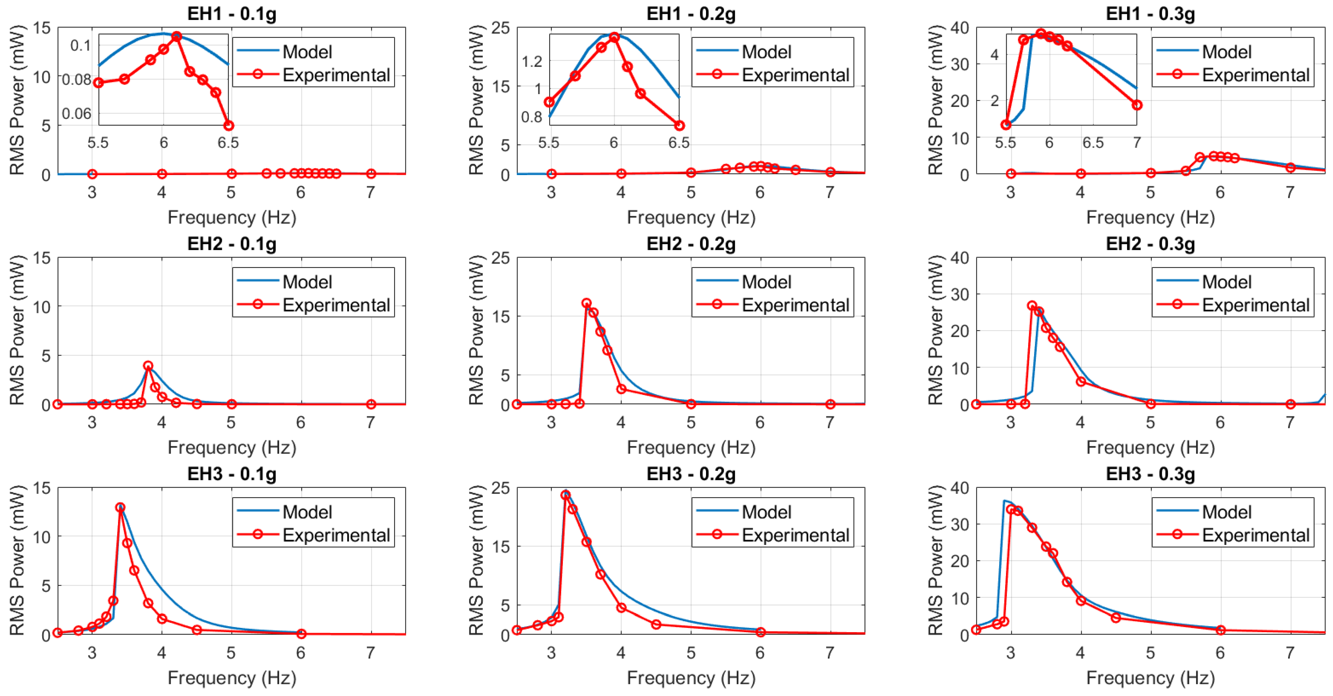
Simulation results need to be compared to experimental results of tests on harvester prototypes. A satisfactory superimposition of experimental and numerical FRFs leads to the validation of the proposed model. Figure 10 reports the comparison between numerical and experimental RMS power FRFs of EH1, EH2, and EH3 for different excitation amplitudes from 0.1 g to 0.3 g. For the purpose of quantifying the preciseness of these models, an error between the numerical and the experimental results in terms of power should be computed. A comparison method can be the evaluation of the relative error in terms of RMS peak power and resonance frequency between the model and the experimental ones:
e r r p e a k % = P p e a k , m o d e l P p e a k , e x p e r i m e n t a l P p e a k , e x p e r i m e n t a l × 100
e r r f r e q % = ω p e a k , m o d e l ω p e a k , e x p e r i m e n t a l ω p e a k , e x p e r i m e n t a l × 100
Table 7 shows the errors obtained for EH1, EH2, and EH3. The peak errors between the model and experimental results are negligible for all the harvesters and different excitation amplitudes. The errors on the resonance frequencies are definitely low, confirming the ability of this model to identify correctly the resonance conditions. This quality is relevant considering the key role of tuning the resonance frequency to the external excitation fundamental frequencies for maximum power generation. The superimposition of the curves leads to overall fine results for all the harvesters. This positive outcome of the study allows confirming the validity of the proposed model to describe the dynamics and transducing mechanism of different-scaled GVEHs. The following step is to perform sensitivity analyses on the fully-parametrized model to define the optimization process of the devices.

3.2. Design Optimization

The validated model can be used for the numerical optimization of the harvester size and performance. The optimization phase is based on a design approach considering the application of the harvester and its constraints. The main design issue for a VEH is to tune its natural resonance frequency to the fundamental excitation frequency of the harvested vibrations. For this reason, the optimization of the generated power is not sufficient and should be performed along with the sizing and tuning process. This paper studies the influence of the magnet’s dimensions on the GVEH asymmetric magnetic suspension characteristics of resonance frequency and equilibrium position. Sensitivity analyses on the diameter and height of both moving and fixed magnets allow us to evaluate the configuration of the suspension that has the target natural frequency of the destined application. Moreover, the study on the equilibrium position is linked to the tube length to give a proper stroke to the moving magnet in the asymmetric suspension. Once the target frequency and equilibrium position are matched, a study on the optimization of the generated power can be performed to maximize the efficiency of the device already complying with the design constraints of the application.
As mentioned in 
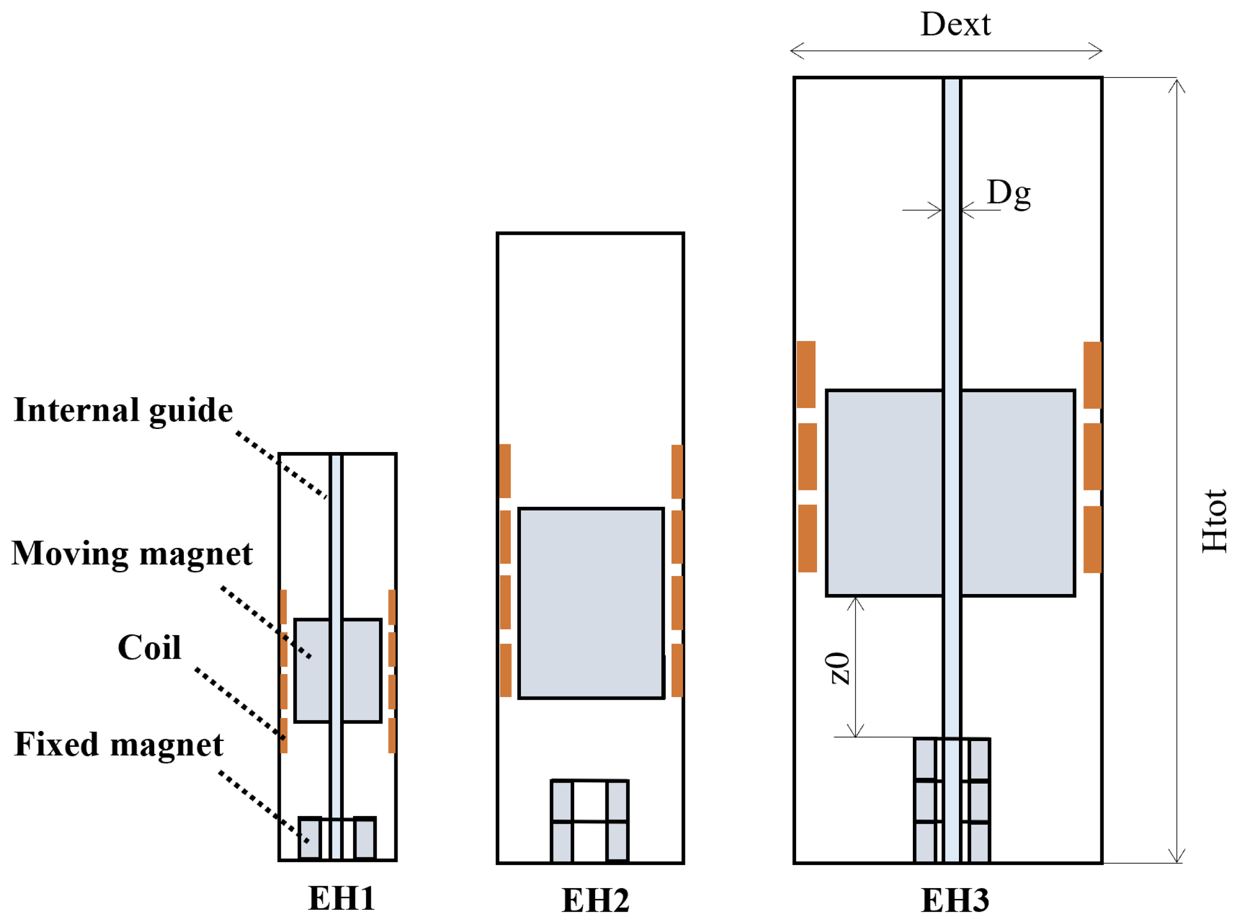
Section 2.1, the asymmetric magnetic suspension consists of only one fixed magnet at the bottom end of the tube and a moving magnet that oscillates under the action of the magnetic repulsive and gravitational restoring forces. Ring-shaped magnets are used in this study due to the use of the internal guide in the tube. Consequently, the magnets parameters that are studied in the design stage are the external diameter, internal diameter, and the height along the axial direction. Table 8 reports the details of the configurations adopted in the numerical model for the sensitivity analyses.
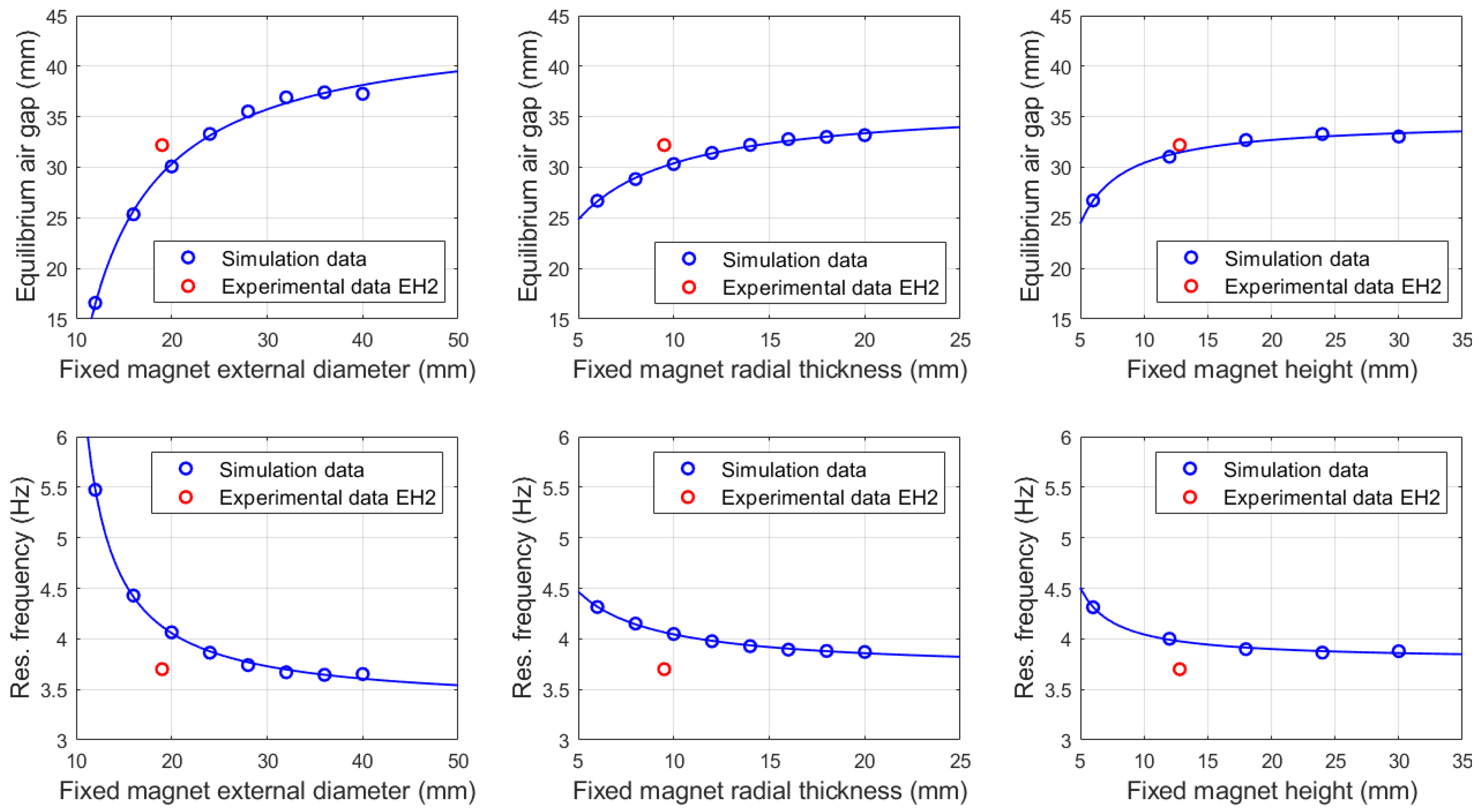
The first sensitivity analysis is performed on the fixed magnet. The external diameter, radial thickness, and height variables are changed one at a time, keeping the others at a constant value. The moving magnet has the dimensions of EH2 configuration for all the sensitivity analyses of the fixed magnet, in order to have a comparison between the simulations and experimental results. Figure 11 reports the outcome of the study on the fixed magnet dimensions. The equilibrium position is referred to the air gap between the upper face of the fixed magnet and the lower face of the moving one. The curves show that increasing the volume of the moving magnet, whether via diameter or height, the resonance frequency decreases and the air gap increases. In particular, the most sensitive parameter is the external diameter as it generates the highest variation in terms of frequency and air gap. This result can be related to the formulation of the resonance frequency of the GVEH linearized system [32]:
ω n = 2 g z 0 = 4 g π m g μ 0 H m o v H f i x
H m o v = H c , m o v A m o v
H f i x = H c , f i x A f i x
where:
  • m is the seismic mass of the moving magnet;
  • g is the gravitational acceleration;
  • z 0 is the equilibrium air gap;
  • μ 0 is the vacuum permeability;
  • H m o v , H f i x are the magnetic field intensities of moving and fixed magnet, respectively;
  • H c , m o v , H c , f i x are the coercive forces of moving and fixed magnet, respectively;
  • A m o v , A f i x are the pole surface areas of moving and fixed magnet, respectively;
Since the field intensity depends on the polar surface area, the greater influence of the diameter parameter with respect to the height is justified. Moreover, increasing the fixed magnet height results in a low increase in the air gap, which is the relative distance between the magnet. However, the absolute position of the moving magnet increases strongly as it is the sum of the air gap and the fixed magnet height, hence the tube length needs to grow to allow a proper stroke to the proof mass. The radial thickness of the fixed magnet influences the tuning of the stiffness in a similar way to the external diameter parameter. In the end, for the purpose of tuning the resonance frequency, it is better to variate the internal or external diameters of the fixed magnet, keeping the height at the minimum possible value in order to reduce the tube length and volume.
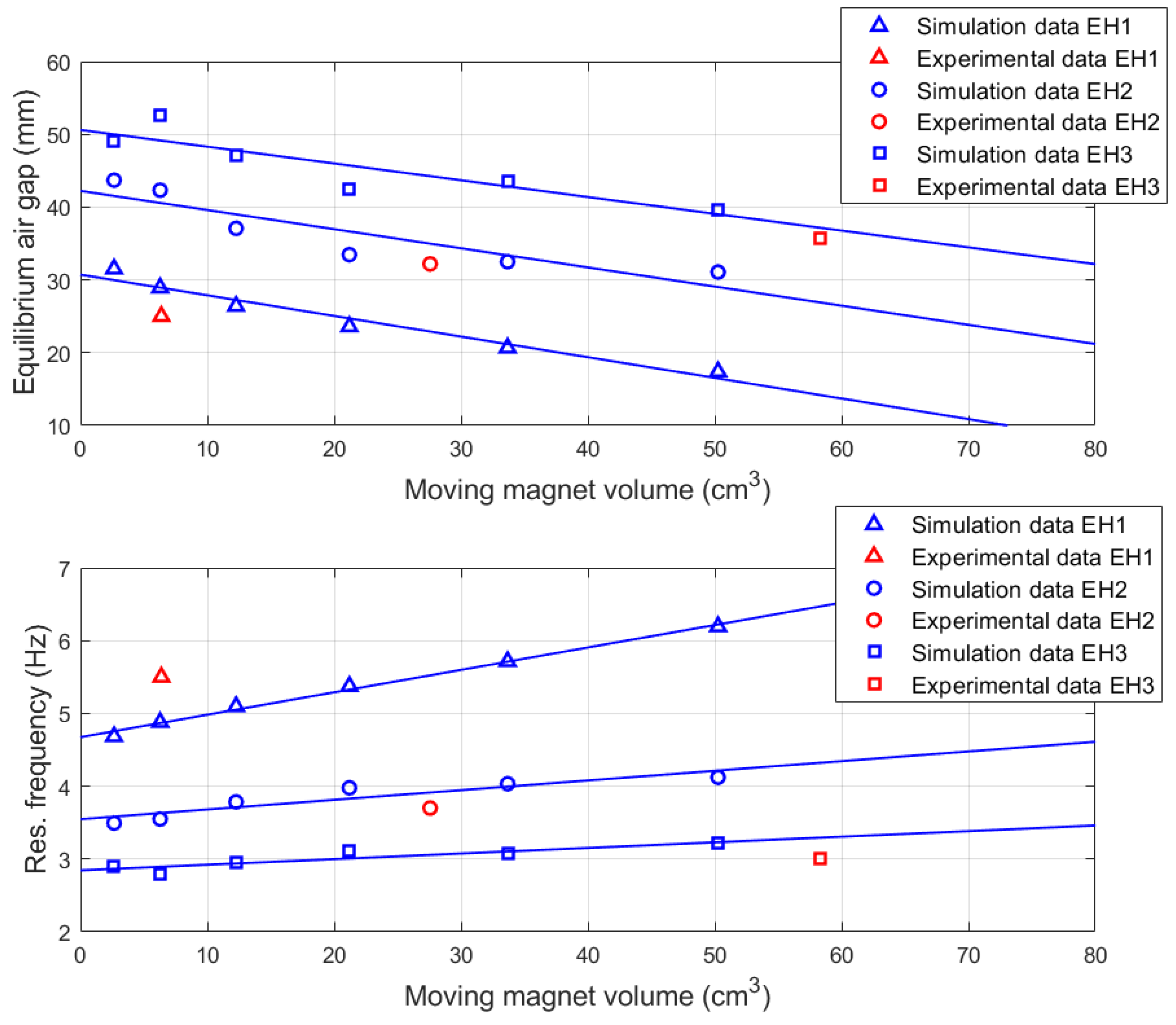
The second sensitivity analysis is performed on the moving magnet. External diameter and height vary together keeping their ratio at a fixed value equal to 1. This study is carried out three times using the fixed magnet of each of the three configurations EH1, EH2, and EH3 in order to insert the experimental results and compare them with the simulation data. The results of the analysis are reported in Figure 12. The trend linear curves for the three configurations interpolate quite well with the experimental results of the real devices. With increasing fixed magnet height, the slope of the trend curve decreases, hence the influence of the moving magnet volume on the resonance frequency and air gap reduces. In all three cases, increasing the moving magnet volume causes the resonance frequency to grow and consequently the air gap to reduce. The influence of the moving magnet on the resonance frequency formulation (17) is not only in terms of magnet field intensity, as happens for the fixed magnet, but also in terms of the mass at the numerator. A sensitivity analysis is performed also on the internal diameter of the moving magnet since an internal guide is used for the reasons explained in Section 2.1. The outcome is not particularly relevant as the influence on the studied variables of natural frequency and air gap is negligible.
Moreover, the moving magnet sensitivity analysis should not be based only on the mechanical characteristics but also on the electromagnetic ones, as it influences the generated power. The expression of the linearized electrical power in resonance condition is the following [32]:
P e = m ζ e Y 0 2 ω n 3 4 ζ t o t 2
where:
  • ζ e is the electromagnetic damping factor;
  • ζ t o t is the sum of electromagnetic and viscous damping factors;
The moving magnet volume influences power in terms of mass and damping factors, both electromagnetic and viscous as it changes the magnetic flux linkage and the friction values. Increasing the moving magnet volume results in increasing power generation, hence the moving magnet should be as big as possible considering the design constraints of the device application. The fixed magnet is chosen for resonance frequency tuning and reducing tube length. The application of these devices is the power supply of wireless IoT sensor nodes in freight trains for structural monitoring. The vertical harvested vibrations on the wagon coaches using Y25 bogies have fundamental frequencies around 4 Hz resulting from Multibody simulations, depending on the train speed [19]. The installation constraints impose that the maximum diameter of the device should not be greater than 20 mm, while the maximum height should be 100 mm. 
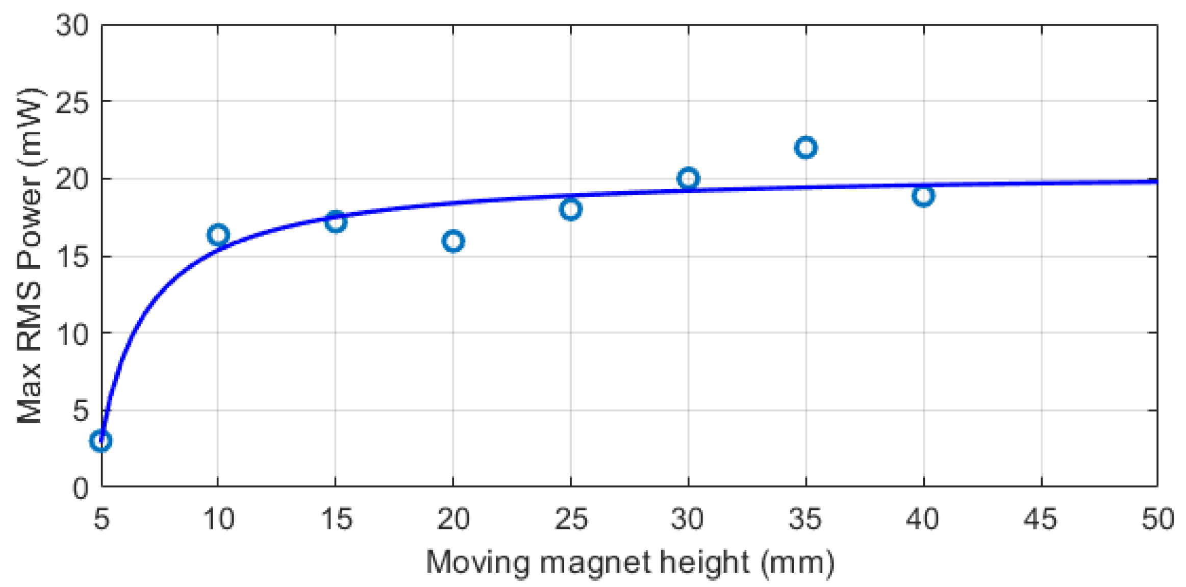
Figure 10 shows that the fixed magnet should have an external diameter of 20 mm for having the targeted resonance frequency of 4 Hz. The internal diameter of 5 mm is chosen for the requirement of an internal guide. The height value is 5 mm in order to minimize the air gap and reduce the tube length. The moving magnet diameter is set as 20 mm in order to have the maximum possible value to increase the generated power. The internal diameter is chosen as small as possible for the same power conversion reason, setting the value at 5 mm as the fixed magnet. The moving magnet height is chosen after a sensitivity analysis on the maximum generated power at resonance condition, reported in Figure 13. The external excitation amplitude is 0.5 g, using the optimized fixed magnet and a coil of 500 turns and an axial length of 10 mm. The chosen moving magnet height is 30 mm as a compromise between power enhancement and tube length for the application.
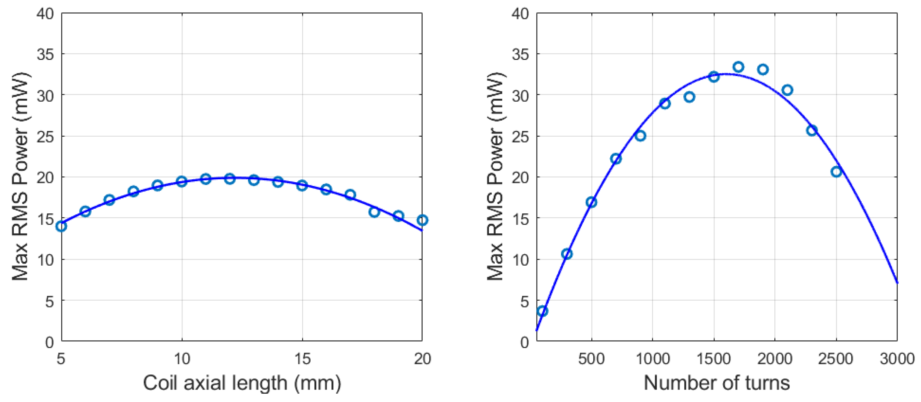
Once the two optimized magnets characterizing the magnetic suspension are defined, the optimization of the coil parameters can be performed. The two main variables are the axial length of the coil and the number of turns, both influencing the resistance value and the magnetic flux linkage distribution (2)–(6). This study allows us to define the combination of the two parameters that maximize the power, as it depends on the electromagnetic damping factor (20). The generated power is evaluated using the optimum resistive load for each coil configuration based on Equation (7). The results of the analyses are reported in Figure 14. The coil axial length analysis is carried out by testing values from 5 to 20 mm, keeping the coil diameter and number of radial turns constant at 500, and applying an external excitation of 0.5 g. The optimum value is between 11 and 12 mm, but a value of 10 mm is chosen to simplify the design and prototyping processes with a negligible loss of performance. Then, the number of turns analysis is performed keeping the axial length fixed at 10 mm, and applying an external excitation of 0.5 g. The resulting optimum value is about 1500 turns with a significant improvement of generated power from about 20 mW to about 32 mW. All the optimized parameters and performances of the final energy harvester are summarised in Table 9.

3.3. Comparison with Devices in Literature

A consistent comparison method between energy harvesters’ performances is the computation of the normalized power density (NPD). This parameter is defined as the ratio between output resonance power and the harvester volume, normalized by the square of acceleration input [8]. Table 10 reports NPD values of the three configurations analyzed in this paper, the optimized harvester and similar devices found in the literature. The performances of the harvesters in this study are aligned with most of the generators developed in other researchers’ works. EH2 has intermediate dimensions between the other two configurations and shows the best NPD value among the others. EH3 has the largest size but generates power not sufficiently higher than EH2, resulting in a low NPD value. The smallest harvester EH1 converts the lowest power amongst the three configurations but is better optimized than EH3 as it presents a solid NPD value. The numerical simulations on the optimized energy harvester enlighten the performance enhancement of the design process in Section 3.2. The new device manages to reach an NPD value of 2.608, which is the highest amongst the devices in the comparative study, improving the EH2 NPD value of about 52%.

4. Conclusions

The aim of this paper is to define a design and optimization procedure for gravitational electromagnetic energy harvesters (GVEHs) based on magnetic suspensions. The proposed optimization strategy is focused not only on maximizing the generated power but also on respecting the device application constraints. This methodology allows us to design the best-performing device suited for a specific application. The optimization process is based on simulations on a proposed numerical model of the GVEHs developed in Ansys Maxwell FEM environment and MATLAB/Simulink. The fully-parametrized model allows us to simulate the transducing mechanism by the definition of the system dynamics and coupling between the mechanical and electromagnetic subsystems. A numerical model is necessary to evaluate the non-linear stiffness and damping characteristics of the system. The model is applied to three configurations of GVEHs having different sizes, referred to as EH1, EH2, and EH3. Experimental tests on a dynamic workbench are performed on the three prototypes for the definition of the Frequency Response Functions of the devices. The satisfactory superimposition between the numerical and experimental results leads to the validation of the proposed model. The validated model can then be used to perform the optimization procedure. The study consists of sensitivity analyses of the effect of the magnet’s dimensions on the mechanical variables of natural frequency and equilibrium position. The results show that by increasing the fixed magnet volume, the system’s natural frequency reduces and the moving magnet equilibrium position grows. In particular, the output variables are more sensitive to the fixed magnet diameter than the height. Consequently, the tuning process is performed only by varying the fixed magnet diameter, keeping its height at the lowest value possible to reduce the tube height and device size. The sensitivity analyses on the moving magnet show that by increasing its volume, the maximum resonance power grows up to a saturated value, whereas the mechanical variables have less sensitivity than the fixed magnet. The devices studied in this paper are destined for freight wagon structural monitoring applications, converting the kinetic energy coming from the ambient vibrations into electrical power for wireless sensor nodes. The design of a GVEH for this application has two main constraints which are the installation-compatible size and the resonance frequency to be tuned to the fundamental excitation frequency of the ambient vibrations on the freight car. The sensitivity analysis outputs allow us to choose the combination of fixed and moving magnets that maximizes the power and comply with the required constraints. Once the magnetic suspension is designed, the electromagnetic circuit needs to be optimized by choosing the coil axial length and a number of turns that maximize the generated power. The optimized transducer resulting from this design process generates a maximum RMS value of the power of 32 mW, applying an external excitation of 0.5 g amplitude at the resonance frequency of 4 Hz. The normalized power density of the optimized harvester is the best amongst the other studied devices in the literature and is 52 % higher than the EH2 configuration. Future works will regard the realization of the optimized prototype and the circuitry for experimental in-field tests on its capability of supplying a wireless sensor node.

Author Contributions

Conceptualization, A.S., C.R. and M.L.M.; methodology, M.L.M. and C.R.; software, M.L.M. and C.R.; validation, A.S., C.R. and M.L.M.; formal analysis, M.L.M. and C.R.; investigation, M.L.M. and C.R.; resources, A.S.; data curation, M.L.M.; writing—original draft preparation, M.L.M.; writing—review and editing, M.L.M.; visualization, M.L.M.; supervision, A.S.; project administration, A.S.; funding acquisition, A.S. All authors have read and agreed to the published version of the manuscript.

Funding

This research received no external funding.

Institutional Review Board Statement

Not applicable.

Informed Consent Statement

Not applicable.

Data Availability Statement

Data available on request due to privacy restrictions.

Conflicts of Interest

The authors declare no conflict of interest.

Abbreviations

The following abbreviations are used in this manuscript:
IoTInternet of Things
AIoTAutonomous Internet of Things
WSNWireless Sensor Node
VEHVibrational Energy Harvester
DOFDegree of Freedom
MVEHMagnetically-suspended Vibrational Energy Harvester
GVEHGravitational Vibrational Energy Harvester
FEMFinite Elements Method
FRFFrequency Response Function
RMSRoot Mean Square
NPDNormalized Power Density

References

  1. Dewan, A.; Ay, S.U.; Karim, M.N.; Beyenal, H. Alternative power sources for remote sensors: A review. J. Power Sources 2014, 245, 129–143. [Google Scholar] [CrossRef]
  2. Shirvanimoghaddam, M.; Shirvanimoghaddam, K.; Abolhasani, M.M.; Farhangi, M.; Barsari, V.Z.; Liu, H.; Dohler, M.; Naebe, M. Towards a Green and Self-Powered Internet of Things Using Piezoelectric Energy Harvesting. IEEE Access 2017, 7, 94533–94556. [Google Scholar] [CrossRef]
  3. Singh, J.; Kaur, R.; Singh, D. Energy harvesting in wireless sensor networks: A taxonomic survey. Int. J. Energy Res. 2021, 45, 118–140. [Google Scholar] [CrossRef]
  4. Bosso, N.; Magelli, M.; Zampieri, N. Application of low-power energy harvesting solutions in the railway field: A review. Veh. Syst. Dyn. 2021, 59, 841–871. [Google Scholar] [CrossRef]
  5. Gljuscic, P.; Zelenika, S.; Blažević, D.; Kamenar, E. Kinetic Energy Harvesting for Wearable Medical Sensors. Sensors 2019, 19, 4922. [Google Scholar] [CrossRef] [PubMed] [Green Version]
  6. Gljušćić, P.; Zelenika, S. Experimental Characterization of Optimized Piezoelectric Energy Harvesters for Wearable Sensor Networks. Sensors 2021, 21, 7042. [Google Scholar] [CrossRef] [PubMed]
  7. Abohamer, M.K.; Awrejcewicz, J.; Starosta, R.; Amer, T.S.; Bek, M.A. Influence of the Motion of a Spring Pendulum on Energy-Harvesting Devices. Appl. Sci. 2021, 11, 8658. [Google Scholar] [CrossRef]
  8. Beeby, S.P.; Torah, R.N.; Tudor, M.J.; Glynne-Jones, P.; O’Donnell, T.; Saha, C.R.; Roy, S. A micro electromagnetic generator for vibration energy harvesting. J. Micromech. Microeng. 2007, 17, 1257–1265. [Google Scholar] [CrossRef]
  9. Muscat, A.; Bhattacharya, S.; Zhu, Y. Electromagnetic Vibrational Energy Harvesters: A Review. Sensors 2022, 22, 5555. [Google Scholar] [CrossRef] [PubMed]
  10. Zhu, D.; Tudor, M.J.; Beeby, S.P. Strategies for increasing the operating frequency range of vibration energy harvesters: A review. Meas. Sci. Technol. 2010, 21, 022001. [Google Scholar] [CrossRef] [Green Version]
  11. Wei, C.; Jing, X. A comprehensive review on vibration energy harvesting: Modelling and realization. Renew. Sustain. Energy Rev. 2017, 74, 1–18. [Google Scholar] [CrossRef]
  12. Carneiro, P.; dos Santos, M.P.S.; Rodrigues, A.; Ferreira, J.A.; Simões, J.A.; Marques, A.T.; Kholkin, A.L. Electromagnetic energy harvesting using magnetic levitation architectures: A review. Appl. Energy 2020, 260. [Google Scholar] [CrossRef] [Green Version]
  13. Foisal, A.R.M.; Hong, C.; Chung, G.S. Multi-frequency electromagnetic energy harvester using a magnetic spring cantilever. Sensors Actuators A Phys. 2012, 182, 106–113. [Google Scholar] [CrossRef]
  14. Zhao, X.; Cai, J.; Guo, Y.; Li, C.; Wang, J.; Zheng, H. Modeling and experimental investigation of an AA-sized electromagnetic generator for harvesting energy from human motion. Smart Mater. Struct. 2018, 27, 085008. [Google Scholar] [CrossRef]
  15. Cronin, S.; Nico, V.; Punch, J. A Comparison of Two Planar Electromagnetic Vibrational Energy Harvesters Designs. J. Electr. Comput. Eng. Res. 2022, 2. [Google Scholar] [CrossRef]
  16. Vidal, J.V.; Rolo, P.; Carneiro, P.M.; Peres, I.; Kholkin, A.L.; dos Santos, M.P.S. Automated electromagnetic generator with self-adaptive structure by coil switching. Appl. Energy 2022, 325, 119802. [Google Scholar] [CrossRef]
  17. Hossain, M.E.; Bird, J.Z.; Albarran, V.; Che, D. Analysis and Experimental Testing of a New Type of Variable Stiffness Magnetic Spring with a Linear Stroke Length. In Proceedings of the 2021 IEEE Energy Conversion Congress and Exposition, ECCE 2021-Proceedings, Vancouver, BC, Canada, 10–14 October 2021; pp. 5961–5965. [Google Scholar] [CrossRef]
  18. Pasquale, G.D.; Somà, A.; Fraccarollo, F. Comparison between piezoelectric and magnetic strategies for wearable energy harvesting. J. Phys. Conf. Ser. 2013, 476, 012097. [Google Scholar] [CrossRef] [Green Version]
  19. Pasquale, G.D.; Somà, A.; Zampieri, N. Design, simulation, and testing of energy harvesters with magnetic suspensions for the generation of electricity from freight train vibrations. J. Comput. Nonlinear Dyn. 2012, 7, 041011. [Google Scholar] [CrossRef]
  20. Russo, C.; Lo Monaco, M.; Fraccarollo, F.; Somà, A. Experimental and numerical characterization of a gravitational electromagnetic energy harvester. Energies 2021, 14, 4622. [Google Scholar] [CrossRef]
  21. Russo, C.; Lo Monaco, M.; Somà, A. Energy harvester duty cycle evaluation for railway vehicle health monitoring. IOP Conf. Ser. Mater. Sci. Eng. 2022, 1214, 012046. [Google Scholar] [CrossRef]
  22. Lo Monaco, M.; Russo, C.; Somà, A. Numerical and experimental performance study of two-degrees-of-freedom electromagnetic energy harvesters. Energy Convers. Manag. X 2023, 18, 100348. [Google Scholar] [CrossRef]
  23. Bijak, J.; Trawiński, T.; Szczygieł, M. Simulation and Investigation of the Change of Geometric Parameters on Voltage Induced in the Energy Harvesting System with Magnetic Spring. Electronics 2022, 11, 1639. [Google Scholar] [CrossRef]
  24. Nguyen, H.T.; Genov, D.A.; Bardaweel, H. Vibration energy harvesting using magnetic spring based nonlinear oscillators: Design strategies and insights. Appl. Energy 2020, 269, 115102. [Google Scholar] [CrossRef]
  25. Phan, T.N.; Aranda, J.J.; Oelmann, B.; Bader, S. Design optimization and comparison of cylindrical electromagnetic vibration energy harvesters. Sensors 2021, 21, 7985. [Google Scholar] [CrossRef]
  26. Hasani, M.; Irani Rahaghi, M. The optimization of an electromagnetic vibration energy harvester based on developed electromagnetic damping models. Energy Convers. Manag. 2022, 254, 115271. [Google Scholar] [CrossRef]
  27. Cepnik, C.; Yeatman, E.M.; Wallrabe, U. Effects of nonconstant coupling through nonlinear magnetics in electromagnetic vibration energy harvesters. J. Intell. Mater. Syst. Struct. 2012, 23, 1533–1541. [Google Scholar] [CrossRef]
  28. Liu, L.; Yuan, F.G. Diamagnetic levitation for nonlinear vibration energy harvesting: Theoretical modeling and analysis. J. Sound Vib. 2013, 332, 455–464. [Google Scholar] [CrossRef]
  29. Ashraf, K.; Khir, M.H.M.; Dennis, J.O.; Baharudin, Z. Improved energy harvesting from low frequency vibrations by resonance amplification at multiple frequencies. Sens. Actuators A Phys. 2013, 195, 123–132. [Google Scholar] [CrossRef]
  30. Kraftmakher, Y. Magnetic field of a dipole and the dipole-dipole interaction. Eur. J. Phys. 2007, 28, 409–414. [Google Scholar] [CrossRef]
  31. Valeria, N.; Elisabetta, B.; Ronan, F.; Jeff, P. A C-Battery Scale Energy Harvester: Part A—System Dynamics. In Proceedings of the ASME 2015 Conference on Smart Materials, Adaptive Structures and Intelligent Systems, Colorado Springs, CO, USA, 21–23 September 2015; Volume 2. [Google Scholar] [CrossRef]
  32. Zhang, Q.; Wang, Y.; Kim, E.S. Electromagnetic Energy Harvester with Flexible Coils and Magnetic Spring for 1–10 Hz Resonance. J. Microelectromech. Syst. 2015, 24, 1193–1206. [Google Scholar] [CrossRef]
  33. Salauddin, M.; Halim, M.A.; Park, J.Y. A magnetic-spring-based, low-frequency-vibration energy harvester comprising a dual Halbach array. Smart Mater. Struct. 2016, 25, 095017. [Google Scholar] [CrossRef]
  34. Costanzo, L.; Schiavo, A.L.; Vitelli, M. Improving the Electromagnetic Vibration Energy Harvester Performance by Using a Double Coil Structure. Appl. Sci. 2022, 12, 1166. [Google Scholar] [CrossRef]
  35. Fan, K.; Cai, M.; Liu, H.; Zhang, Y. Capturing energy from ultra-low frequency vibrations and human motion through a monostable electromagnetic energy harvester. Energy 2019, 169, 356–368. [Google Scholar] [CrossRef]
  36. Aldawood, G.; Nguyen, H.T.; Bardaweel, H. High power density spring-assisted nonlinear electromagnetic vibration energy harvester for low base-accelerations. Appl. Energy 2019, 253, 113546. [Google Scholar] [CrossRef]
  37. Constantinou, P.; Roy, S. A 3D printed electromagnetic nonlinear vibration energy harvester. Smart Mater. Struct. 2016, 25, 095053. [Google Scholar] [CrossRef]
Figure 1. Schematic representation of the harvesters.
Applsci 13 02736 g001
Figure 2. (a) Scheme of harvester mechanical subsystem. (b) Scheme of harvester electric circuit.
Applsci 13 02736 g002
Figure 3. Simulink block scheme.
Applsci 13 02736 g003
Figure 4. (a) Magnetic field vectors for EH3. (b) Magnetic flux linkage for EH3.
Applsci 13 02736 g004
Figure 5. Magnetic force curves for EH1, EH2, and EH3.
Applsci 13 02736 g005
Figure 6. Exponential decay of viscous damping for EH1.
Applsci 13 02736 g006
Figure 7. Electromagnetic coupling coefficient and damping curves.
Applsci 13 02736 g007
Figure 8. Experimental setup logic flow.
Applsci 13 02736 g008
Figure 9. Experimental setup picture.
Applsci 13 02736 g009
Figure 10. Experimental and model FRFs comparison for EH1, EH2, and EH3.
Applsci 13 02736 g010
Figure 11. Fixed magnet sensitivity analysis.
Applsci 13 02736 g011
Figure 12. Moving magnet sensitivity analysis.
Applsci 13 02736 g012
Figure 13. Moving magnet sensitivity analysis.
Applsci 13 02736 g013
Figure 14. Coil axial length and number of turns sensitivity analyses.
Applsci 13 02736 g014
Table 1. Main dimensions of the energy harvesters.
Configuration D ext (mm) H tot (mm) D g (mm) z 0 (mm)
EH13190820
EH236170-37
EH356220546
Table 2. Main dimensions of the magnets.
EH1EH2EH3
H m o v = 30 mm H m o v = 30 mm H m o v = 30 mm
Moving magnet D m o v , e x t = 20 mm D m o v , e x t = 30 mm D m o v , e x t = 50 mm
D m o v , i n t = 10 mm D m o v , i n t = / D m o v , i n t = 5 mm
H f i x = 6 mm H f i x = 12 mm H f i x = 18 mm
Fixed magnet D f i x , e x t = 20 mm D f i x , e x t = 20 mm D f i x , e x t = 20 mm
D f i x , i n t = 10 mm D f i x , i n t = 10 mm D f i x , i n t = 10 mm
Table 3. Main characteristics of the coils.
Configuration H coil (mm) D coil (mm) N turns R coil ( Ω )
EH1530480100
EH2103828070
EH31558710270
Table 4. Static simulations results.
Configuration z 0 (mm) k 0 (N/m) f n (Hz)
EH125525.0
EH2351023.8
EH3422133.4
Table 5. Viscous damping values of the energy harvesters.
Configuration c vis (Ns/m) c vis , crit (Ns/m) ζ vis
EH10.163.290.049
EH20.278.080.034
EH30.9619.00.05
Table 6. Electric quantities used for tests.
ConfigurationCoil Number R coil ( Ω ) R load , opt ( Ω )
EH1270100
EH24100150
EH33270570
Table 7. Peak and frequency relative errors for EH1, EH2, and EH3.
Excitation Amplitude (g) err peak ( % ) err freq ( % )
EH1 = 1.64EH1 = 1.64
0.1EH2 = 3.84EH2 = 0
EH3 = 2.13EH3 = 2.94
EH1 = 1.96EH1 = 0
0.2EH2 = 5.25EH2 = 0
EH3 = 4.04EH3 = 0
EH1 = 1.30EH1 = 1.70
0.3EH2 = 3.16EH2 = 3.03
EH3 = 7.13EH3 = 3.33
Table 8. Sensitivity analyses descriptions.
Sensitivity AnalysisFixed MagnetMoving Magnet
Fixed magnet external diameter D fix , ext  = 12–40 mm1 D m o v , e x t = 30 mm
D f i x , i n t = 10 mm D m o v , i n t = /
H f i x = 12 mm H m o v = 30 mm
Fixed magnet radial thickness D f i x , e x t = 20 mm D m o v , e x t = 30 mm
D fix , int = 0–14 mm D m o v , i n t = /
H f i x = 12 mm H m o v = 30 mm
Fixed magnet height D f i x , e x t = 20 mm D m o v , e x t = 30 mm
D f i x , i n t = 10 mm D m o v , i n t = /
H fix = 6–30 mm H m o v = 30 mm
Moving magnet external diameter and height 2 D f i x , e x t = 20 mm D mov , ext = 15–40 mm
D f i x , i n t = 10 mm D m o v , i n t = /
H f i x = 6/12/18 3 mm H mov = 15–40 mm
Moving magnet internal diameter D f i x , e x t = 20 mm D m o v , e x t = 30 mm
D f i x , i n t = 10 mm D mov , int = 0–16 mm
H f i x = 12 mm H m o v = 30 mm
1 Bold characters represent the variable dimensions of the corresponding sensitivity analysis. 2 Diameter and height vary together with a fixed ratio equal to 1. 3 The analyses are performed for the three fixed magnet dimensions of EH1, EH2, and EH3, respectively.
Table 9. Parameters and performances of the optimized energy harvester.
ComponentParametersOutput VariableValue
Fixed magnet D f i x , e x t = 20 mmNatural frequency4 Hz
D f i x , i n t = 5 mm
H f i x = 5 mm
Moving magnet D m o v , e x t = 20 mmAir gap30 mm
D m o v , i n t = 5 mmTube ext. diameter25 mm
H m o v = 30 mmTube length100 mm
Coil H c o i l = 10 mmMaximum power32 mW @ 4 Hz, 0.5 g
N t u r n s = 1500
R c o i l = 280 Ω
Table 10. Normalized power density of different harvesters.
Ref.Resonance Frequency (Hz)Max. Power (mW)Volume (cm3)NPD (mWcm−3 g−2)
[14]563.9 @ 5 Hz 6 g6.770.262
[32]5.54.3 @ 5.5 Hz, 0.5 g120.00.143
[33]111.09 @ 11 Hz, 0.4 g32.760.133
[34]807.22 @ 80 Hz, 2 g49.180.040
[35]91.15 @ 9 Hz, 0.8 g9.160.196
[36]1161.3 @ 11 Hz, 0.4 g194.61.97
[37]4.52.9 @ 4.5 Hz, 1 g6.000.480
[22]3.4, 6.7 18.25 @ 3.4 Hz, 0.4 g2260.230
EH15.74.6 @5.7 Hz, 0.3 g67.930.752
EH23.326.8 @ 3.3 Hz, 0.3 g173.01.72
EH3333.9 @ 3 Hz, 0.3 g541.90.695
EH opt432 @ 4 Hz, 0.5 g49.092.608
1 Two-degrees-of-freedom configuration.
Disclaimer/Publisher’s Note: The statements, opinions and data contained in all publications are solely those of the individual author(s) and contributor(s) and not of MDPI and/or the editor(s). MDPI and/or the editor(s) disclaim responsibility for any injury to people or property resulting from any ideas, methods, instructions or products referred to in the content.

