Article

Gap and Force Adjustment during Laser Beam Welding by Means of a Closed-Loop Control Utilizing Fixture-Integrated Sensors and Actuators

Production Technology Group, Technische Universität Ilmenau, 98693 Ilmenau, Germany
*
Authors to whom correspondence should be addressed.
Appl. Sci. 2023, 13(4), 2744; https://doi.org/10.3390/app13042744
Submission received: 20 January 2023 / Revised: 16 February 2023 / Accepted: 18 February 2023 / Published: 20 February 2023
(This article belongs to the Special Issue Laser Material Processing and Thermal Joining Process)

Abstract

:
The development of adaptive and intelligent clamping devices allows for the reduction of rejects and defects based on weld discontinuities in laser-beam welding. The utilization of fixture-integrated sensors and actuators is a new approach, realizing adaptive clamping devices that enable in-process data acquisition and a time-dependent adjustment of process conditions and workpiece position by means of a closed-loop control. The present work focused on sensor and actuator integration for an adaptive clamping device utilized for laser-beam welding in a butt-joint configuration, in which the position and acting forces of the sheets to be welded can be adjusted during the process (studied welding speeds: 1 m/min, 5 m/min). Therefore, a novel clamping system was designed allowing for the integration of inductive probes and force cells for obtaining time-dependent data of the joint gap and resulting forces during welding due to the displacement of the sheets. A novel automation engineering concept allowed the communication between different sensors, actuators and the laser-beam welding setup based on an EtherCAT bus. The subsequent development of a position control and a force control and their combination was operated with a real time PC as master in the bus system and proved the feasibility of the approach based on proportional controllers. Finally, the scalability regarding higher welding speeds was demonstrated.

1. Introduction

Laser-material processing is gaining importance in different fields of applications due to the contactless energy input, high intensities and high flexibility in manufacturing components based on various materials [1,2]. Laser-beam welding is highly attractive for these reasons and widely used in different industrial sectors, e.g., for manufacturing processes in automotive industry [3], electronics [4], and household appliances [5,6]. These industries are accompanied by large production quantities and require automated processes. The demands on economic efficiency are increasing at the same time, i.e., minimization of rejects and increased flexibility of production are required.
Adaptive and flexible production processes are gaining relevance in the field of laser welding for these reasons, allowing an in-process adjustment of various control parameters. First, this requires process data to be obtained from the welding process itself and these must be related to the material behavior and resulting seam imperfections [7]. Second, an adjustment of process conditions during welding must occur. Mostly, laser-dependent conditions are considered for an active adjustment nowadays, e.g., via controlling the beam power for specific events [8] or continuously [9], manipulating the beam shape [10] or adjusting the beam position [11]. This enables deviations in penetration depth, melt-pool geometry and laser-beam trajectory to be addressed and minimized, for example, while actively manipulating the workpiece position or geometry is not currently state of the art.
The welding process leads to an inhomogeneous and transient temperature distribution, resulting in residual stresses that can cause deformation [12]. Distortion is based on plastic deformation and induces a displacement of the parts to be welded, which affects the energy deposition in the workpiece [13] and causes changes in weld-seam geometry and penetration depth in particular [14]. The process is interrupted when the displacement reaches a critical gap size, i.e., the melt pool is no longer able to bridge the gap between the parts to be welded, or the laser beam is transmitted through the gap in the case of butt welds [15]. These challenging weld discontinuities are material dependent [12] and well-known for laser beam welding of high-alloy steels highly tending to thermal distortion due to due their low thermal conductivity and high thermal expansion [15,16]. A precise prediction is not possible, as batches have each different material histories, which then also manifest themselves in differently pronounced distortion [16]. This problem can be countered by exceedingly massive and therefore cost-intensive fixtures [17]–or by an adjustment the workpiece position or clamping situation directly. It was shown that the manipulation of the workpiece and the clamping situation can significantly effect resulting residual stresses and thus distortion [18]. The possibility of workpiece handling and welding via two robots was also demonstrated, however, high distortion was found to be critical for such non-adaptive jigless welding setups [19]. Therefore, certain defect patterns caused by distortion require process control and workpiece manipulation capabilities to counteract workpiece displacement by adaptively adjusting the resulting gaps through the clamping device.
This requires the utilization of sensors to detect the gap on the one hand and actuators to enable mechanical intervention on the other hand. The gap can be detected directly via non-contact sensors integrated in the processing optics or mounted to it, e.g., by triangulation [20] or imaging [21]. A different approach is the integration of sensors into the clamping device being in contact with the sheet to measure the displacement of the workpiece to provide a value of the gap size indirectly [15,16]. This offers the advantage of measuring the gap at a constant position during the welding process to obtain a fundamental understanding of the ongoing processes over time [15,16] and to avoid a negative effect of misalignment between laser beam and butt joint position [22].
The use of automated actuators is advantageous regarding reproducibility and reduced rejection [23] in general. The further development of intelligent welding fixtures enables precise welding processes with improved versatility [24] by combining actuators and sensors. This allows for an automatic clamping force and position correction for assembly [25,26] or the adjustment of the clamping intensity during milling [27]. However, the process of laser-beam welding requires high-speed control systems from data acquisition over data processing to the mechanical intervention in the process due to the high processing speeds, as shown for the welding of galvanized steels in lap joints [28]. Clamping devices combining actuators and sensors would be able to provide a further knowledge on the process besides the avoidance of seam imperfections. The process behavior can be described in more detail by measuring specific parameters over time. In the case of welding high-alloy steels in butt joint configuration, distortion and resulting gap sizes are key parameters to ensure a stable process.
This paper demonstrated the development of a clamping device for butt joints enabling the time-dependent acquisition of gap sizes and occurring forces due to thermal distortion in laser-beam welding by fixture integrated sensors. The additional integration of mechanical actuators in the clamping system further enabled the development of closed-loop controls utilizing gap size, occurring forces, or both combined as controlled variables for the purpose of an adaptive clamping device. The findings offer starting points for a further improvement of the welding process by adaptive and intelligent clamping devices, jigless welding and fixture design.

2. Materials and Methods

2.1. Laser Beam Welding

The laser welding process was carried out by a Trumpf TruDisk 5000.75 disc laser with a processing head Precitec YW52. The clamping device (see Section 2.2) was fixed in its position while a six-axis robot Kuka KR60 HA with Kuka KR C4 control was carrying out the feed by moving the processing head. The parameters used are listed in Table 1. The necessary beam power was examined in preliminary trials to achieve a full penetration weld and kept constant for both welding speeds considered.
AISI 304 (1.4301/X5CrNi18-10) was welded in butt joint configuration with technical zero gap at process start. The specimen geometry was 300 mm in length and 50 mm in width with a constant thickness of 1 mm. The welding process was carried out over the whole sheet length. The specimens were cut to size by laser beam cutting to ensure flatness of the specimens, high cutting-edge quality and neglectable distortion due to the cutting process. A high-speed camera Photron SA-X2 was used to track the sheet positions to validate the clamping concept (recording rate: 1000 Hz). A sample size of 3 welds was carried out for each parameter set and control strategy.

2.2. Concept for an Adaptive Clamping Device with Sensors and Actuators

Figure 1a shows a schematic figure for the clamping strategy and the positions of the sensors for acquiring the sheet displacement as an index for gap size. Sheet ① was fixed within the clamping device by clamping jaw ⓐ while sheet ② was freely moveable in y-direction. This behavior was ensured by a gap between clamping jaw ⓑ and sheet ② of 0.1 mm. The distance between both clamping jaws was set to 30 mm. The laser beam was moved between both clamping jaws carrying out the weld. Three inductive probes (Millimar P2004M) positioned along the specimen were used to determine the sheet displacement in y-direction representing the gap size at different positions. A resolution of 3 µm was reached within a range of 4 mm measuring length in total. The signals were amplified utilizing carrier frequency amplifiers (Dewetron DAQP-CFB2). The probes were set to zero before welding started. It should be noted that the probes acted on the sheet with a measuring force of 0.75 N ± 0.15 N [29].
The resulting forces were determined by temperature-compensated load cells type K-12 from Lorenz Messtechnik (LC1-2) for measuring tensile and compression forces with a maximum value of ±1000 N at an accuracy class of 0.25% (Figure 1b). The signal was amplified via LCV measuring amplifier from Lorenz Messtechnik. Both load cells were mounted to linear actuators L59-A with trapezoidal spindle and linear guide from Nanotec Electronic (LA1-2). The linear motor provided a force of up to ±1000 N at a maximum speed of 0.08 m/s and a resolution of 10 μm/step. The linear unit could extend to a stroke length of 25 mm. The linear motor had the advantage over conventional drives that a specified angle of the rotor could be approached and held in a targeted manner. The minimum step width of the rotor is 7.2°. The self-retaining spindle prevented the system to be moved in case of an external force, i.e., only the linear motor was able to change the position of the linear actuator. C5E-EtherCAT from Nanotec was used as motor controller. The actuators LA1-2 and therefore both load cells LC1-2 were positioned at begin and end of the sheet outside the inductive probes.

2.3. Design of the Adaptive Clamping Device

The presented schemes of the clamping situation and the gap measurement (see Figure 1a) must be implemented in a single setup with the force measurement and the mechanical actuators (see Figure 1b) to obtain an adaptive clamping device for laser beam welding in butt joint configuration. This requires both mechanical engineering and automation engineering to ensure all functionalities and to enable the manipulation of the process by means of a closed-loop control. The design of the system is shown in the following.
Figure 2 shows the fixture design as complete rig with six-axis robot and processing head in perspective view. The clamping device allowed to weld samples with a length up to 500 mm in butt joint configuration and different sheet thicknesses up to 3 mm. The fixed clamping of sheet ① by clamping jaws ⓐ was realized by two pneumatic Festo linear swing clamps CLR-25-20-L-P-A, each one realizing a clamping force of approx. 230 N at 6 bar of air pressure. The chosen design ensured a determined clamping situation without using a continuous bar as single clamping jaw. In contrast, clamping jaw ⓑ was designed as a continuous bar to ensure the movement of sheet ② in the y-direction while limiting the movement in z-direction to 0.1 mm. It should be noted that the moveability of sheet ② was limited to the y-direction only if the actuators and load cells were connected to it, otherwise the sheet can move freely in the x-y plane. The continuous bar also protected sensors and actuators against spatters from the welding process.
The top view shows the arrangement of sensors and actuators along sheet ②. Sensors and actuators were color-coded based on the schematic figure in Section 2.2. The uniform distribution along the sheet ensures information about the entire weld seam length. In the context of this paper, the sensor positions were implemented in the positions given in Section 2.2 for welding sheets with a length of 300 mm but can be further relocated to other positions for realizing welds up to 500 mm in length.
An exemplarily detailed view on sensor and actuator integration is provided by Figure 3 for inductive probe IP2 and linear actuator LA1 with the associated load cell LC1. A prismatic centering in a V-groove ensured the position of each inductive probe along x-direction due to its rotationally symmetric housing. A clamp joint set the position in y-direction that enabled the measurement of the inductive probes against the sheet edge position utilizing a connector clamped to the sheet edge. The measured displacement is representative for the resulting joint gap in the butt joint [15,16]. The movability of the sheet in the y-direction was ensured for this purpose which is why a gap of 0.1 mm between clamping jaw ⓑ and sheet ② was realized. Each linear actuator was lined up with a linear guide and a load cell which is shown for LA1 and LC1 in Figure 3. The linear guide was based on a plain bearing and acted as connecting element between linear actuator and load cell. The load cell was screw joint to the linear guide and an additional connecting element that contained two thrust screws with thrust heads that created a force-fit joint between sheet ② and the linear actuator and the load cell. The connection between sheet ② and the sensors and actuators limited its moveability in x-direction.
Figure 4 shows the realized adaptive clamping device in the laser welding setup. In addition to the design shown before, a high-speed camera (see Section 2.1) was included to provide further information on the forming gap between both sheets and to prove the validity of the clamping concept (sheet ① fixed, sheet ② moveable in y-direction).

2.4. Automation Engineering for Sensor/Actuator Integration and Control

EtherCAT from Beckhoff served as bus system based on the international IEC standard IEC 61158-1 protocol [30] ensuring communication between different components via real-time Ethernet. The EtherCAT bus system linked the sensors, the motor controllers of the linear actuators and the load cells with a real time PC as control unit. A schematic figure is given in Figure 5. TwinCAT from Beckhoff was running on the real time PC to create a virtual programmable logic controller (PLC) working as EtherCAT master while all other components in the EtherCAT network were considered slaves. The additional, real-time capable measurement and control system ADwin from Jäger Messtechnik was integrated to the bus system via EtherCAT Pro II EtherCAT-SL plug-in card.
This procedure enabled the integration of the analog sensor signals from inductive probes IP1-3 and load cells LC1-2 and a digital signal from the robot control regarding start/stop of the closed-loop control. The conversion of analog values into digital values was done with a 16-bit multiplexer and an operating range of ±10 V was addressed for sensor signals. The signals were transferred to the bus system at a frequency of 1000 Hz. It should be noted that the load cell signals were preprocessed in advance to reduce noise by applying a moving average over 50 data points within the ADwin program.
The PLC program queried all values to be recorded from the sensors via the EtherCAT bus system. The signals were evaluated in the PLC that included the software-based implementation of the control-loop and then forwarded the change in the controlled variable to the motor controllers via the EtherCAT bus system. It should be noted that the closed-loop control strategies were implemented on the virtual PLC since the latencies are thereby shortest (determined latency: 10 ms).
A proportional controller was utilized in all cases due to its fast response times even if small deviations cannot be corrected completely. Ziegler-Nichols method [31] was utilized for determining the proportional gains for load cells (proportional gain: 1) and inductive probes (proportional gain: 1000) which were kept constant in all cases considered. The PLC program was utilized for data recording of all sensors in addition. The realized control cabinet in testing mode is shown in Figure 6. The circuit diagram including the dimensioning of the automatic fuses and the cable cross-sections was designed for an operating voltage of 24 V for the control cabinet. Furthermore, the assignment of the slots on the ADwin measurement and control system was determined, and the arrangement of the bus nodes was specified. Three sockets (230 V) were provided for running the real time PC and additional devices.

3. Results and Discussion

3.1. Uncontrolled Welding Process and Validation of Clamping Concept

Figure 7 shows the top view of an uncontrolled weld with unhindered gap formation. Sheet ② was able to move freely within the y-direction since the actuators and the load cells were not connected to it. The weld started in zero gap but was interrupted after approximately 205 mm due to the increasing gap size with longer process duration. It should be noted that the gap formation changes over time and the gap may close after the welding process during cooling [15].
A detailed view of the gap size occurring time-dependent due to the unhindered sheet displacement is shown in Figure 8a. The gap that occurred was time-delayed in comparison to the process start at time zero corresponding to the initial keyhole penetration. It was assumed that there is no significant effect on gap formation by conduction-mode welding at the start of the process, as the keyhole is formed in times of less than 1 ms [32]. The gap started to increase for the first probe IP1 close to the sheet edge at process start while probe IP2 and IP3 follow its order along the weld seam. The gap size increased until the weld reached the corresponding measuring point in the x-direction, or the weld has been discontinued because of a too excessive gap size. A gap size of more than 0.5 mm was reached at probe IP3 when the process was interrupted.
The intended clamping situation could be achieved with the developed clamping device, i.e., the position of sheet ① is almost constant over time while sheet ② can move freely in the y-direction (see Figure 8b). Sheet ② remained almost unchanged in the z-direction while Figure 8a showed an unhindered gap opening. This suggests that the gap of 0.1 mm between clamping jaw ⓑ and sheet ② (see Section 2.1) was sufficiently dimensioned to allow for a free movement in the y-direction.
A rigid clamping was considered in addition for the uncontrolled process to provide information on occurring forces during welding (see Figure 9). The tensile forces have a positive sign, the compressive forces have a negative sign. Load cell LC 1 was located at the start of the sheet and load cell LC 2 was located at the end of the sheet as described in Section 2.1. Load cell LC 1 showed a short period under compressive forces directly after process start. The load cell LC 2 at the end of the sheet did not record any change in load at this point. The tensile forces caused by the cooling process and shrinkage of the weld seam started to predominate over the further course of the process for load cell LC 1. The force at load cell LC 2 increased shortly after the weld started to form and then continued to decrease until the resulting tensile force became predominant due to the cooling process from approximately 15 s onwards. The experiment was carried out several times to obtain the acting compressive forces whereby an average value of −95.6 N ± 6.9 N was reached (n = 3). It should be noted that the forces follow the description of resulting residual stresses during welding when it comes to changes from compressive stresses to tensile stresses over time [33].
It can be stated that tensile and compressive forces and gap formation behave differently along the weld seam, i.e., they are dependent on time and position. If the process is to be controlled, action must be taken accordingly at different times and at different positions. Three approaches based on the integrated sensors were followed for this reason: position control, force control and force-position control.

3.2. Position Control

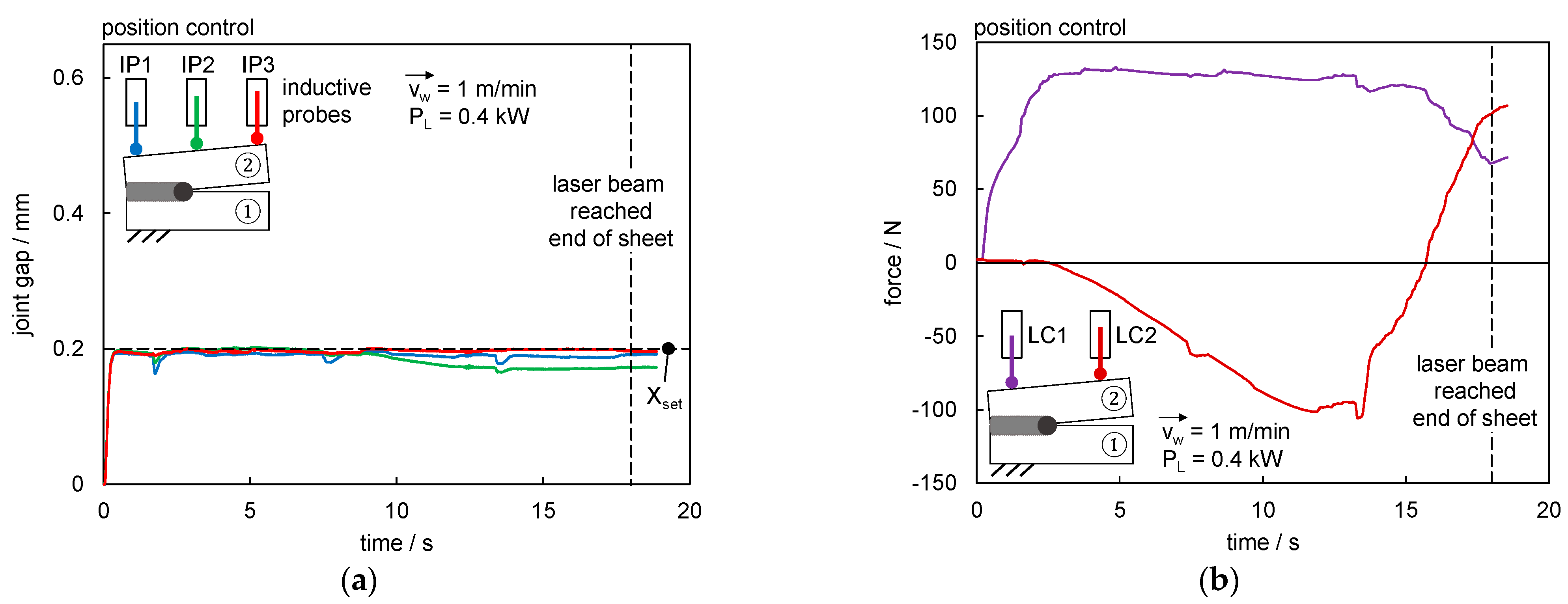
The gap opening was detected via the inductive probes during closed-loop position control (Figure 10). The setpoint value of the position control was selected to be smaller than the value of the maximum gap bridgeability. The linear actuators pulled the sheet ② from zero gap to the specified setpoint value of the gap at the start of the welding process. If the inductive probes detected deviations, it was compensated by the linear actuators. Both gap sizes were set independently of each other. The gap measured at the beginning of the sheet by inductive probe IP1 was assigned to linear actuator LA1 and inductive probe IP3 was assigned to linear actuator LA2 for the gap size at the end of the sheet.
The gap size was put to 0.2 mm as setpoint value Xset which is equal to approximately 75% of the focal diameter and the gap had been bridgeable for the laser welding process without discontinuities. Figure 11a shows the results for the gap width based on inductive probe measurements at three positions. The gap was adjusted to the setpoint value directly at the process start, had reached 0.2 mm quickly and could be considered constant during the welding process. Deviations, e.g., at approximately 1.7 s, 7.6 s and 13.5 s were well compensated. The maximum gap size reached was 0.203 mm at the position of IP2. Contraction of the sheets occurred during solidification and cooling of the weld led to a decrease in gap dimension as noticeable for IP1 and IP2. The position controller started compensating the deviation by reducing forces for LC1 with increasing process times (see Figure 11b). LC2 showed the largest deviation, indicating that there were further variances between the two controlled positions at LC1 (associated to IP1) and LC2 (associated to IP3) that could no longer be fully compensated due to the already solidified weld.
The forces during position control showed comparable values to the rigid clamping even if the increase in force is steeper for load cell LC1 at the process start and for load cell LC2 after approx. 13.5 s. Maximum tensile forces of 133 N and compressive forces of −105 N acted during the welding process.
The control of the gap was thus successfully demonstrated and allowed the setting of nearly constant gap sizes during welding while avoiding the occurrence of any seam discontinuities. The control loop had a sufficient stability and did not tend to overshoot.

3.3. Force Control

The force was measured via load cells LC1 and LC2 during closed-loop force control (Figure 12). The maximum compressive force during welding was expected for the rigid clamping situation where the movement of sheet ② in the y-direction was completely prevented, hence the maximum strain occurred. Therefore, the setpoint values of the forces were selected to be smaller than the value of the maximum compressive force in rigid clamping which was determined to be approximately 100 N (see Section 3.1). The linear actuators adjusted sheet ② to reach the specified setpoint value of the compression force at the start of the welding process. If a load cell detected deviations, it was compensated by the related linear actuator. Hence, the force was controlled individually for both positions of the linear actuators by assigning load cell LC1 to linear actuator LA1 and load cell LC2 to linear actuator LA2.
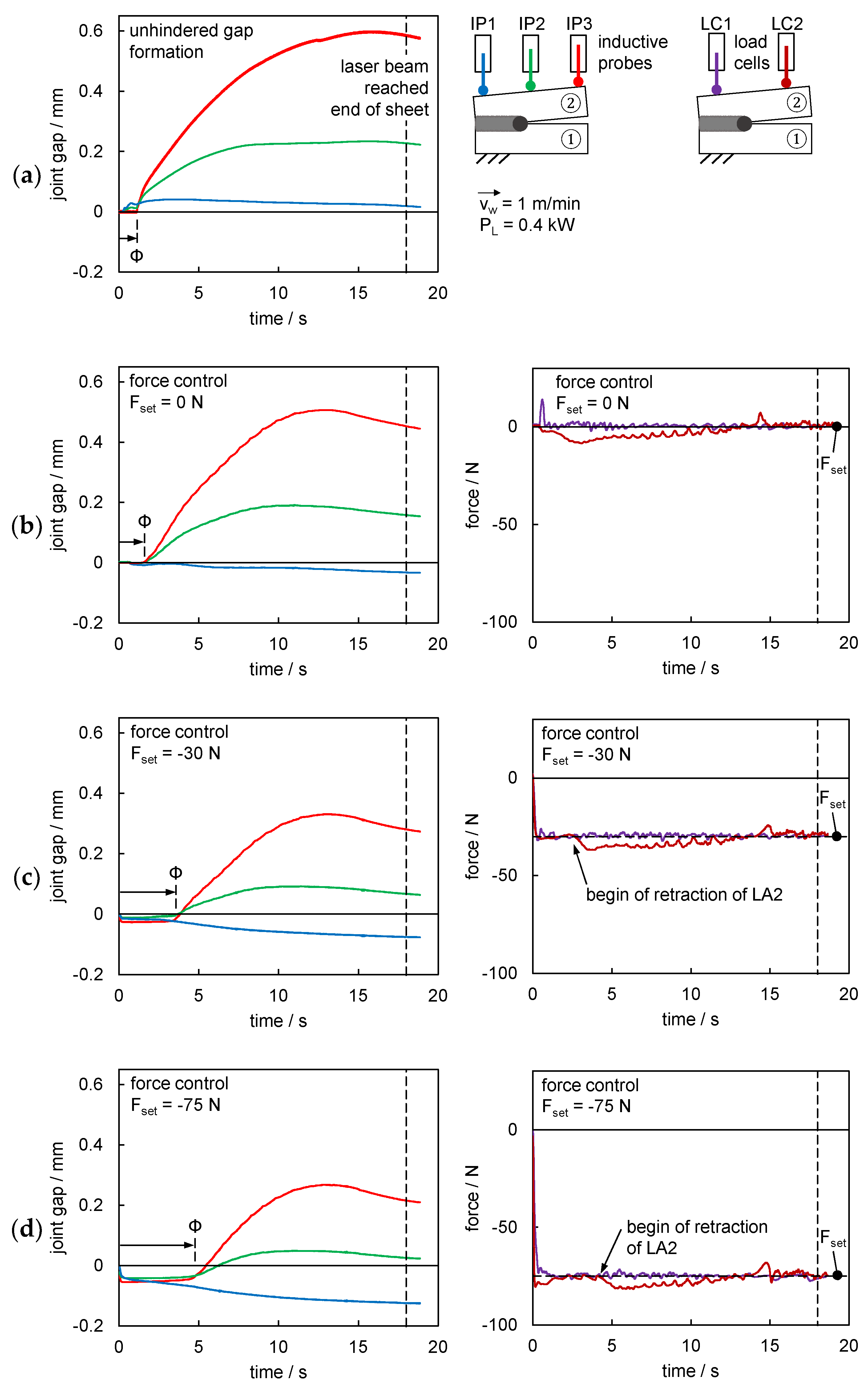
Figure 13 shows the resulting gap over time for the different inductive probes IP1-3 based on different setpoint forces Fset compared to an unhindered gap formation. The unhindered gap formation (uncontrolled process, no rigid clamping) in Figure 13a was already discussed in Section 3.1 but is used as a reference for describing the effects based on the force control. The time interval Φ is introduced to compare the different times needed for the joint gap to increase in size for different forces adjusted by the closed-loop control.
Figure 13b shows a setpoint value Fset of 0 N and depicts the resulting joint gaps and the measured forces over time. An influence on the gap formation can already be seen for nominal zero forces, i.e., the gap size measured at IP1 did not increase significantly compared to the unhindered process in Figure 13a. The negative gap dimension obtained can be explained by the contraction of the sheets after the welding process, i.e., the outer dimension of the welded sheets in the y-direction was reduced compared to the initial value and the inductive probes measure against the outer edge. The maximum value of the joint gap at IP3 was significantly reduced by 0.09 mm to 0.51 mm. The set force at the begin of the sheet was reached rapidly and remains rather constant. However, for LC1 a peak was determined in each case for a setpoint value of 0 N indicating a strong reaction to the occurring compressive forces at the begin of the welding process. A slightly increased compression force (max. ΔF = −8.6 N) than specified was measured at LC2 because of the chosen control strategy for the first half of the welding time. The proportional gain of the controller could be increased at this point, but there is a risk of the system overshooting and it should be considered that each load cell operated at the lower limit of its resolution. It should be noted that the small peaks of the force curves that occur continuously are due to the proportional controller and do not represent signal noise. The smaller deviations in the controlled force values did not have a noticeable effect on the joint gap, so any negative effect on the position of sheet ② could be ruled out. A comparison to the uncontrolled rigid clamping (see Section 3.1) shows the difference in characteristics clearly.
The effect of a further increase in the set compression force Fset to −30 N is shown in Figure 13c. The time Φ until the gap size is increasing was significantly extended. It can be assumed that the gap opening started after the process force is greater than the setpoint compression force. It should be noted that the linear actuator started retraction before Φ was reached, i.e., the force control delayed the gap formation. A further decrease in gap size down to 0.33 mm as maximum value at IP3 was reached while the control kept the forces on a quite constant level resulting in an average weld seam length of 260 mm. It should be noted that even a small compression force of −5 N led to an increase in weld seam length from 197 mm (uncontrolled process, no rigid clamping) to 244 mm on average until the occurrence of a weld discontinuity. A further increase of the compression force Fset to −75 N shows the behavior again more pronounced (see Figure 13d). The gap formation at time Φ was delayed even further, the retraction of the actuator LA2 occurred later due to the higher process forces required for an increase in gap width and weld discontinuities occurred only once after 285 mm in three trials.
An increase in setpoint compression forces Fset resulted in longer weld seams and reduced discontinuities. The forces were kept quite constant despite the utilization of a simple proportional controller. In all cases, the compressive forces acting in the welding process had to exceed the specified setpoint forces for the gap width to increase. Until this point in time, the gap remained closed.

3.4. Force-Position Control

The force-position control was considered as last control concept and allowed the combination of the two previous strategies. The force-position control allowed to verify whether it is possible to vary the gap during the process or to set it to constant values after the process start. The control loop has been designed to operate as a force control until a certain gap dimension gapswitch is reached, and then to switch to position control (see Figure 14). Both positions Xset and forces Fset at the start and end of the sheet metal were again controlled separately from each other.
Figure 15 shows the resulting joint gap (a) and forces (b) over time. A compression force of −30 N was used as Fset until a gap width of 0.2 mm (gapswitch) was reached. After reaching gapswitch at IP3, the gap was controlled to stay constant (Xset = 0.2 mm). The acting compression force of −30 N at process start led to a longer time Φ until the gap started to increase as expected based on the force-controlled process discussed in Section 3.3. Afterwards, the gap width started to grow for IP2 and IP3 while the forces remained constant due to the closed-loop control. The gap was kept constant after reaching gapswitch by adjusting the forces that can be seen clearly in Figure 15b.
This demonstrated that it was also possible to react to different events during welding. A relatively low welding speed of 1 m/min have been considered in the results shown so far, which is why the possibility of scaling to higher processing speeds will be considered in the following.

3.5. Scalability to Higher Welding Speeds

The scalability to higher welding speeds had been examined in the following for a better understanding of the system behavior at more industrially relevant welding speeds. The welding speed was scaled up from 1 m/min to 5 m/min for this purpose.
Figure 16 shows the comparison of the joint gap of both welding speeds considered for the unhindered gap formation and closed-loop force control. The gap size is significantly reduced for higher welding speeds due to the reduction of dissipated heat. This was also evident in the energy per unit length required for full penetration welding, which was 24 kJ/m at 1 m/min and 12 kJ/m at 5 m/min (see Section 2.1, Table 1). The qualitative characteristics were generally comparable, i.e., the resulting gap decreased as the setpoint value of the compression force Fset was increased. It should be noted that the gap to be bridged also decreased with increasing welding speed due to a reduced melt pool volume as shown in Figure 16 for two welded examples at 1 m/min and 5 m/min. An additional example is a force of −30 N, where an average weld length of 280 mm at 5 m/min and of 260 mm at 1 m/min was achieved despite different gap values of 0.09 mm to 0.32 mm.
A consideration of the time-dependent behavior is shown in Figure 17 for the force-position control at a welding speed of 5 m/min. A force Fset of −30 N should be kept constant until a gap width of 0.05 mm (gapswitch, approximately 20% of the focal diameter) had been reached (Xset = 0.05 mm). Due to a higher welding speed and a reduced energy per unit length, a smaller melt pool size was reached resulting in reduced gap bridgeability, as mentioned. Thus, a gap smaller than for 1 m/min was selected to demonstrate the possibility of a force-position control at 5 m/min welding speed. The control was initiated at time zero and reached the setpoint value Fset of −30 N after 0.22 s for LC1 and 0.12 s for LC2. The different times resulted from the larger effect of the welding process at the beginning of the sheet compared to the end of the sheet. The joint gap at IP1 never exceeded 0.05 mm which is why the controller continued to keep the force at −30 N. A greater difference between the nominal and actual force occurred from approximately 1 s onwards at LC2 before a gap of 0.05 mm (gapswitch) was reached. The rapid increase in gap size could not be fully compensated which may be attributed to the characteristic offset of a proportional controller until the closed-loop control was switched from force to position control after approx. 1.8 s. When the switching condition was reached at IP3, a further gap opening was strongly delayed immediately while the control tried to reach the Xset value of 0.05 mm. However, a maximum gap size of 0.058mm after approximately 0.35 s was obtained. The gap size at IP3 was slightly decreasing afterwards to a minimum gap size of 0.042 mm while a maximum force of −106 N at LC2 occurred. The characteristic for dropping below the setpoint gap value Xset was favorable in terms of avoiding weld discontinuities.
At this point, it can be stated that a transfer to higher welding speeds was possible and has been implemented. The integrated sensors and actuators can intervene quickly enough, although further tuning of the controller certainly offers potential for reduced deviations between setpoint and actual values.

4. Conclusions

The paper addressed the integration of sensors and actuators in clamping devices to fundamentally demonstrate the possibility of adaptive process control for laser beam butt welding of high-alloy steels. A system was developed that allowed for the determination of joint gaps based on the position of the sheets to be welded, occurring forces and their manipulation by mechanical actuators. Closed-loop controls of position, force and force-position combined were developed by utilizing a proportional controller and starting from the verification of the concept regarding the clamping situation and a traceability of gap formation and forces during welding.
The position control enabled a nearly constant joint gap close to the setpoint value and minor deviations were corrected quickly during welding. The force control was demonstrated for different setpoint forces. Increasing compression forces resulted in a further delayed opening of the joint gap, longer weld seams and reduced discontinuities. The forces were kept quite constant despite the utilization of a proportional controller. A force-position control was developed as a final control concept and allowed for the combination of the two previous strategies and proved the possibility to switch different controlled variables during the welding process. An overshoot of the control loop could not be observed at any time. The scalability of the closed-loop control to higher welding speeds was shown by increasing the welding speed from 1 m/min up to 5 m/min for force-controlled and force-position controlled welds, although a further tuning of the controller certainly offers potential for reduced deviations between setpoint and actual values.

Author Contributions

Conceptualization, L.S., H.F., K.S. and J.P.B.; methodology, L.S., H.F., K.S. and J.P.B.; software, H.F.; formal analysis, H.F.; investigation, L.S. and H.F.; data curation, H.F. and K.S.; writing—original draft preparation, K.S. and L.S.; writing—review and editing, J.P.B.; visualization, K.S., L.S. and H.F.; funding acquisition, J.P.B. and K.S. All authors have read and agreed to the published version of the manuscript.

Funding

The Project ‘Engineering for Smart Manufacturing (E4SM)–Engineering of machine learning-based assistance systems for data-intensive industrial scenarios’ is supported by the Carl-Zeiss-Stiftung (funding number: P2017-01-005). The authors would like to thank the funding agency for the financial support and the continuous assistance during the project runtime.

Institutional Review Board Statement

Not applicable.

Informed Consent Statement

Not applicable.

Data Availability Statement

The data presented in this study are available on request from the corresponding author.

Acknowledgments

The authors would like to thank the Carl-Zeiss-Stiftung and all partners of the E4SM project, in particular Michael Groß (TU Ilmenau).

Conflicts of Interest

The authors declare no conflict of interest.

References

  1. Olivera, J.P.; Zeng, Z.; Omori, T.; Zhou, N.; Miranda, R.M.; Braz Fernandes, F.M. Improvement of damping properties in laser processed superelastic Cu-Al-Mn shape memory alloys. Mater. Des. 2016, 98, 280–284. [Google Scholar] [CrossRef]
  2. Olivera, J.P.; Shamsolhodaei, A.; Shen, J.; Lopes, J.G.; Goncalves, R.M.; de Brito Ferraz, M.; Picarra, L.; Zeng, Z.; Schell, N.; Zhou, N.; et al. Improving the ductility in laser welded joints of CoCrFeMnNi high entropy alloy to 316 stainless steel. Mater. Des. 2022, 219, 110717. [Google Scholar] [CrossRef]
  3. Khan, M.S.; Ali, S.; Westerbaan, D.; Duley, W.; Biro, E.; Zhou, Y.N. The effect of laser impingement angle on the optimization of melt pool geometry to improve process stability during high-speed laser welding of thin-gauge automotive steels. J. Manuf. Process. 2022, 78, 242–253. [Google Scholar] [CrossRef]
  4. Pawlak, R.; Tomczyk, M.; Walczak, M. Durability and reliability enhancement of selected electronic components achieved by laser technologies. In Proceedings of the 2017 MIXDES-24th International Conference Mixed Design of Integrated Circuits and Systems, Bydgoszcz, Poland, 22–24 June 2017; pp. 459–462. [Google Scholar] [CrossRef]
  5. Wang, Z.; Dirrenberger, J.; Lapouge, P.; Dubent, S. Laser treatment of 430 ferritic stainless steel for enhanced mechanical properties. Mater. Sci. Eng. A 2022, 831, 142205. [Google Scholar] [CrossRef]
  6. Schricker, K.; Drebing, A.; Seibold, M.; Bergmann, J.P. Laser-assisted joining of AISI 304 thin sheets with polymers. Procedia CIRP 2020, 94, 531–536. [Google Scholar] [CrossRef]
  7. Masinelli, G.; Le-Quang, T.; Zanoli, S.; Wasmer, K.; Shevchik, S.A. Adaptive laser welding control: A reinforcement learning approach. IEEE Access 2020, 8, 103803–103814. [Google Scholar] [CrossRef]
  8. Seibold, M.; Schricker, K.; Bergmann, J.P. Systematic adjustment of the joining time in pulsed laser beam welding of aluminum-copper joints by means of a closed-loop control. J. Adv. Join. Process. 2022, 5, 100104. [Google Scholar] [CrossRef]
  9. Blug, A.; Carl, D.; Höfler, H.; Abt, F.; Heider, A.; Weber, R.; Nicolosi, L.; Tetzlaff, R. Closed-loop control of laser power using the full penetration hole image feature in aluminum welding processes. Phys. Procedia 2011, 12, 720–729. [Google Scholar] [CrossRef]
  10. Mi, Y.; Mahade, S.; Sikström, F.; Choquet, I.; Joshi, S.; Ancona, A. Conduction mode laser welding with beam shaping using a deformable mirror. Opt. Laser Technol. 2022, 148, 107718. [Google Scholar] [CrossRef]
  11. Cieszynski, W.; Zieba, M.; Rainer, J. Real time trajectory correction system of optical head in laser welding. Acta Mech. Et Autom. 2015, 9, 265–269. [Google Scholar] [CrossRef]
  12. Radaj, D. Heat Effects of Welding: Temperature Field, Residual Stresses, Distortion; Springer: Berlin/Heidelberg, Germany, 1992. [Google Scholar] [CrossRef]
  13. Krantzsch, C.; Abels, P.; Kaierle, S.; Poprawe, R.; Schulz, W. Coaxial process control during laser beam welding of tailored blanks. In Proceedings of SPIE 3888 2000, High-Power Lasers in Manufacturing; SPIE: Bellingham, WA, USA, 2000; pp. 472–482. [Google Scholar] [CrossRef]
  14. Jacques, L.; El Ouafi, A. Experimental investigation of laser welding process in butt-joint configurations. World J. Eng. Technol. 2017, 5, 77–89. [Google Scholar] [CrossRef] [Green Version]
  15. Nagel, F.; Simon, F.; Hildebrand, J.; Bergmann, J.P. Optimisation strategy for the laser beam welding of high-alloyed steels. Weld. Cut. 2017, 16, 256–262. [Google Scholar]
  16. Walther, D.; Schmidt, L.; Schricker, K.; Junger, C.; Bergmann, J.P.; Notni, G.; Mäder, P. Automatic detection and prediction of discontinuities in laser beam butt welding utilizing deep learning. J. Adv. Join. Process. 2022, 6, 100119. [Google Scholar] [CrossRef]
  17. Simon, F.; Nagel, F.; Hildebrand, J.; Bergmann, J.P. Numerical optimization of a laser welding process by use of an additional heat source. In Mathematical Modelling of Weld Phenomena 11; Verlag der Technischen Universität Graz: Graz, Austria, 2016; pp. 565–574. [Google Scholar]
  18. Schenk, T.; Richardson, I.M.; Kraska, M.; Ohnimus, S. A study on the influence of clamping on welding distortion. Comput. Mater. Sci. 2009, 45, 999–1005. [Google Scholar] [CrossRef]
  19. Högel, R. Next generation of Jigless Robot Welding. Laser Tech. J. 2017, 4, 39–41. [Google Scholar] [CrossRef] [Green Version]
  20. Wu, J.; Wang, P.; Fu, X.; Liu, B.; Chen, J. A novel seam measuring method of complex tight butt joint for laser welding. In Proceedings of the 2009 IEEE International Conference on Mechatronics and Automation, Changchun, China, 9–12 August 2009; pp. 2548–2553. [Google Scholar] [CrossRef]
  21. Gao, X.; Chen, Y. Detection of micro gap weld using magneto-optical imaging during laser welding. Int. J. Adv. Manuf. Technol. 2014, 73, 23–33. [Google Scholar] [CrossRef]
  22. Jeng, J.; Mau, T.; Leu, S. Gap inspection and alignment using a vision technique for laser butt joint welding. Int. J. Adv. Manuf. Technol. 2000, 16, 212–216. [Google Scholar] [CrossRef]
  23. Arote, T.; Bhorkade, V.; Burkul, G.; Sangle, P.; Marathe, K.S. Improvement in welding fixture for riser frame of seating arrangement in automobile vehicle. Int. J. Innov. Res. Sci. Eng. 2017, 3, 269–274. [Google Scholar]
  24. Seloane, W.T.; Mpofu, K.; Ramatsetse, B.I.; Modungwa, D. Conceptual design of intelligent reconfigurable welding fixture for rail car manufacturing industry. Procedia CIRP 2020, 91, 583–593. [Google Scholar] [CrossRef]
  25. Erdem, I.; Asbjörnsson, G.; Kihlman, H. Workpiece force and position control for active and flexible fixtures in assembly. Int. J. Adv. Manuf. Technol. 2021, 112, 333–346. [Google Scholar] [CrossRef]
  26. Gonzalo, O.; Seara, J.M.; Guruceta, E.; Izipizua, A.; Esparta, M.; Zamakona, I.; Uterga, N.; Aranburu, A.; Thoelen, J. A method to minimize the workpiece deformation using a concept of intelligent fixture. Robot. Comput.-Integr. Manuf. 2017, 48, 209–218. [Google Scholar] [CrossRef]
  27. Nee, A.Y.C.; Senthil Kumar, A.; Tao, Z.J. An intelligent fixture with a dynamic clamping scheme. Proc. Inst. Mech. Eng. Part B J. Eng. Manuf. 2000, 214, 183–196. [Google Scholar] [CrossRef]
  28. Tenner, F.; Eschner, E.; Lutz, B.; Schmidt, M. Development of a joining gap control system for laser welding of zinc-coated steel sheets driven by process observation. J. Laser Appl. 2018, 30, 032402. [Google Scholar] [CrossRef]
  29. Mahr. Millimar P2004 Manual. Available online: https://metrology.mahr.com/fileadmin/assets/files/Millimar--3723158--BA--2004-2010-2104--DE-EN--2017-07-20.pdf (accessed on 15 December 2022).
  30. International Electrotechnical Commission. EN IEC 61158-1: Industrial Communication Networks-Fieldbus Specifications-Part 1: Overview and Guidance for the IEC 61158 and IEC 61784 Series; International Electrotechnical Commission: Geneva, Switzerland, 2019. [Google Scholar]
  31. Ziegler, J.G.; Nichols, N.B. Optimum settings for automatic controllers. Trans. ASME 1942, 64, 759–768. [Google Scholar] [CrossRef]
  32. Ki, H.; Mazumder, J.; Mohanty, P.S. Modeling of laser keyhole welding: Part II. simulation of keyhole evolution, velocity, temperature profile, and experimental verification. Metall. Mater. Trans. A 2002, 33, 1831–1842. [Google Scholar] [CrossRef]
  33. van der Aa, E.M. Local Cooling during Welding: Prediction and Control of Residual Stresses and Buckling Distortion. Ph.D. Thesis, Delft University of Technology, Delft, The Netherlands, 2007. [Google Scholar]
Figure 1. Schematic figure of the clamping situation and position of sensors and actuators (dimensions in millimeter): (a) Gap measurement via inductive probes IP1-3; (b) Linear actuators LA1-2 and force measurement via load cells LC1-2.
Applsci 13 02744 g001
Figure 2. Design of the adaptive clamping device in perspective and top view.
Applsci 13 02744 g002
Figure 3. Design details for integration of inductive probes and linear actuators and load cells (half section view).
Applsci 13 02744 g003
Figure 4. Realization of adaptive clamping device in laser welding setup (housings of load cells and actuators removed).
Applsci 13 02744 g004
Figure 5. Schematic figure of the bus system for sensor and actuator integration.
Applsci 13 02744 g005
Figure 6. Realized control cabinet for sensor and actuator integration and control in testing mode.
Applsci 13 02744 g006
Figure 7. Top view of an uncontrolled weld with unhindered gap formation (vw = 1 m/min, PL = 0.4 kW).
Applsci 13 02744 g007
Figure 8. Unhindered gap formation (vw = 1 m/min, PL = 0.4 kW): (a) Gap measurement via inductive probes; (b) High-speed recording of sheet edges at the end of the specimen at different times.
Applsci 13 02744 g008
Figure 9. Force measurement of a rigid clamping for an uncontrolled process (vw = 1 m/min, PL = 0.4 kW).
Applsci 13 02744 g009
Figure 10. Closed-loop position control.
Applsci 13 02744 g010
Figure 11. Closed-loop position control (vw = 1 m/min, PL = 0.4 kW): (a) Gap measurement via inductive probes; (b) Force measurement via load cells.
Applsci 13 02744 g011
Figure 12. Closed-loop force control.
Applsci 13 02744 g012
Figure 13. Closed-loop compression force control (vw = 1 m/min, PL = 0.4 kW): (a) unhindered gap formation; (b) setpoint value 0 N; (c) setpoint value −30 N; and (d) setpoint value −75 N.
Applsci 13 02744 g013
Figure 14. Closed-loop force-position control.
Applsci 13 02744 g014
Figure 15. Closed-loop force-position control (vw = 1 m/min, PL = 0.4 kW): (a) gap measurement via inductive probes; and (b) force measurement via load cells.
Applsci 13 02744 g015
Figure 16. Comparison of maximum gap width for unhindered gap formation and force-controlled process at 1 m/min and 5 m/min welding speed and examples of weld seams.
Applsci 13 02744 g016
Figure 17. Closed-loop force-position control (vw = 5 m/min, PL = 1.0 kW): (a) gap measurement via inductive probes; and (b) force measurement via load cells.
Applsci 13 02744 g017
Table 1. Laser welding parameters.
ParameterSymbolValue and Dimension
Focal diameterdf280 µm
Wavelengthλ1030 nm
Angle of incidence-0° (perpendicular to surface)
Welding speedvw1 m/min5 m/min
Resulting welding time for 300 mm weld seam length-18 s3.6 s
Laser beam powerPL400 W1000 W
Energy per unit lengthE24 kJ/m12 kJ/m
Disclaimer/Publisher’s Note: The statements, opinions and data contained in all publications are solely those of the individual author(s) and contributor(s) and not of MDPI and/or the editor(s). MDPI and/or the editor(s) disclaim responsibility for any injury to people or property resulting from any ideas, methods, instructions or products referred to in the content.

