Article

Engineering Design of the European DEMO HCPB Breeding Blanket Breeder Zone Mockup

Institute for Neutron Physics and Reactor Technology (INR), Karlsruhe Institute of Technology (KIT), Hermann-von-Helmholtz-Platz 1, 76344 Eggenstein-Leopoldshafen, Germany
*
Author to whom correspondence should be addressed.
Appl. Sci. 2023, 13(4), 2081; https://doi.org/10.3390/app13042081
Submission received: 25 November 2022 / Revised: 26 January 2023 / Accepted: 27 January 2023 / Published: 6 February 2023
(This article belongs to the Special Issue Advances in Fusion Engineering and Design)

Abstract

:
The Helium Cooled Pebble Bed (HCPB) breeding blanket is one of the two driver-blanket candidates for the European fusion demonstration power plant (EU DEMO) within the framework of the EUROfusion Consortium. As the EU DEMO program is going, testing of mockups becomes increasingly important. In this article, the engineering design of a first-ever breeder zone mockup of the EU DEMO HCPB breeding blanket is reported. The mockup will be tested in the high-pressure, high temperature, helium facility (HELOKA) at Karlsruhe Institute of Technology. This mockup will act as a test rig to validate heat transfer correlations, CFD software, and thermal hydraulics systems codes. As pressure equipment, the mockup shall conform to the latest European Union Pressure Equipment Directive 2014/68/EU. The design description, rationale and test matrix, and corresponding analyses are discussed and presented.

1. Introduction

Within the EUROfusion framework, Karlsruhe Institute of Technology (KIT) is leading the development of the Helium Cooled Pebble Bed (HCPB) breeding blanket [1], one of the two driver-blanket candidates (e.g., HCPB and the Water Cooled Lead Lithium—WCLL [2]) selected for DEMO and to be tested in ITER [3]. Over the last decade, many design activities on the HCPB have been performed [4,5,6]. As we are consolidating the concept, there is an increasing need to proceed to qualify the blanket concept through testing. A series of design and experimental activities for testing the components of the HCPB blanket were conducted in the last decade [7,8,9,10,11,12]. The HETRA experimental campaigns on the helium-cooled First Wall of the HCPB test blanket module (TBM) were conducted to investigate the thermal hydraulic (heat removal and pressure drop) effectiveness of the surface roughness in the First Wall channels in 8 MPa pressure and 300 °C temperature conditions [7]. The mass flow distribution of the HCPB TBM coolant system were performed in the GRICAMAN experimental facility [8]. The heat transfer and pressure drop of transverse ribs and V-shaped ribs in the First Wall channel of the HCPB breeding blanket were experimentally studied in a pressurized air facility [9]. The PREMUX experimental investigations were done to benchmark the existing finite element method codes used for the thermo-mechanical assessment of the lithium ceramic pebble beds and to measure the thermal conductivity of the lithium ceramic pebble beds [10]. Experimental campaigns reproducing the DEMO-relevant thermal hydraulics conditions during normal and off-normal situations of the FW of HCPB breeding blanket were done in a large-scale helium loop facility [11,12]. More recently, activities to validate the heat transfer correlations for the smooth and rough annular channels and to investigate the nonuniform flow patterns of the return flow in the annular channel of the fuel-breeder pin concept of the HCPB breeding blanket were started [13]. This present article reports the engineering design of the first-ever breeder zone mockup of the fuel-breeder pin concept of the HCPB breeding blanket. The scope is to validate the heat transfer correlations for the smooth and rough annular channels, computational fluid dynamics (CFD) codes, and thermal hydraulics system codes.

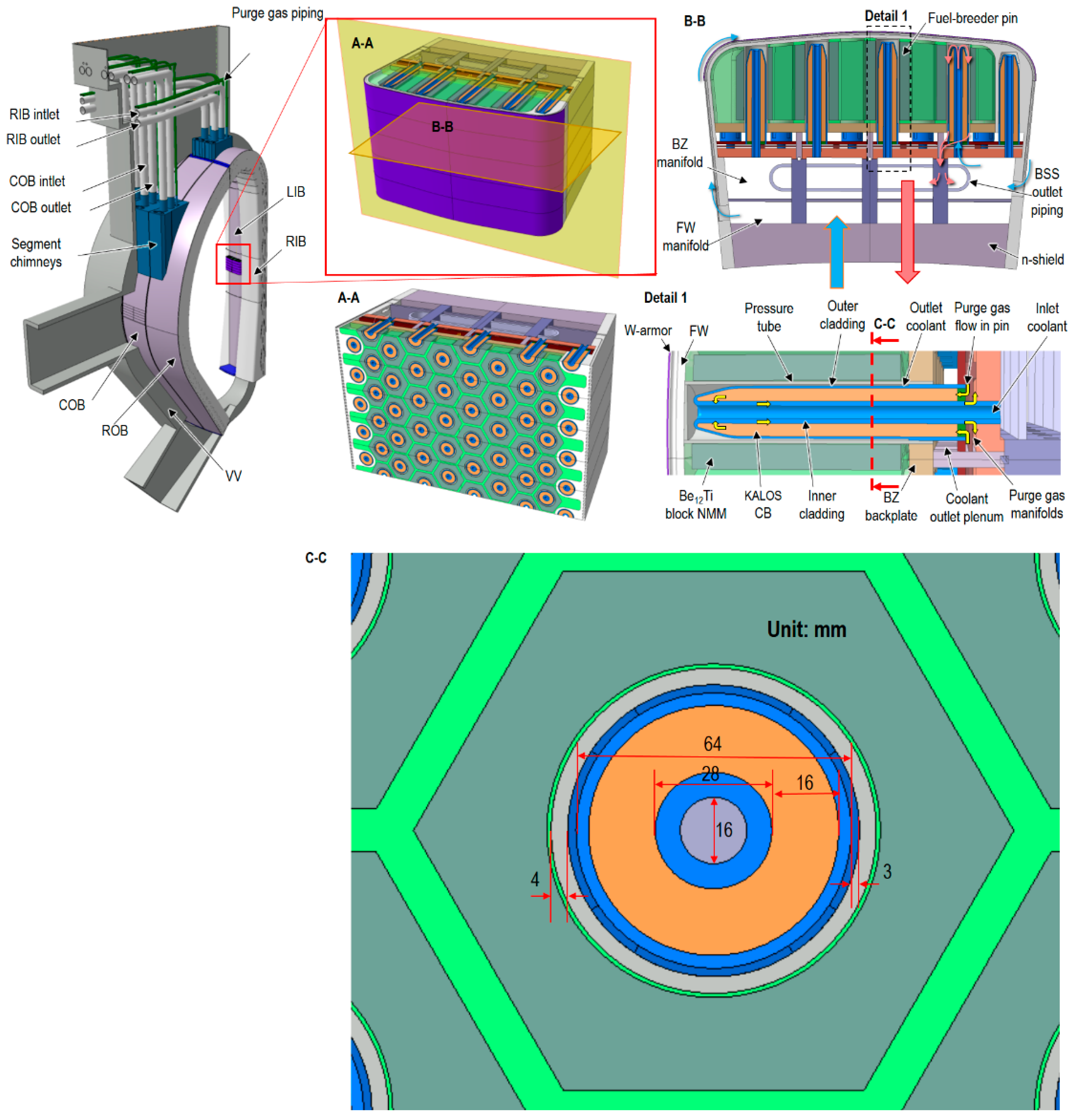
2. Design of the Mockup

The design status and descriptions of the fuel-breeder pin concept of the HCPB blanket is described elsewhere [1]. For completeness, the HCPB blanket is shown in Figure 1. The axial length of the fuel-breeder pin is about 570 mm. The other dimensions of the fuel-breeder pin are shown in Figure 1C-C. For the fuel-breeder pin concept, even with a roughness of Rz = 260 µm on the surfaces of the annular channel of the fuel-breeder pin, the pressure drop of the blanket unit-slice was about 0.34 bar. While for the previous cooling plate concept of HCPB [14], the pressure drop of the blanket unit-slice was about 2 bar when using smooth channel [14]. This implies the superiority of the fuel-breeder pin concept in terms of lower pressure drop. For qualifying the HCPB blanket concept, it is planned that the testing of this mockup will be done under DEMO-relevant conditions in the high temperature, high-pressure facility—Helium Loop Karlsruhe (HELOKA) [15]. It is wished that this mockup would act as a validation rig for better understanding of the design margins to ensure a feasible operation of this concept.

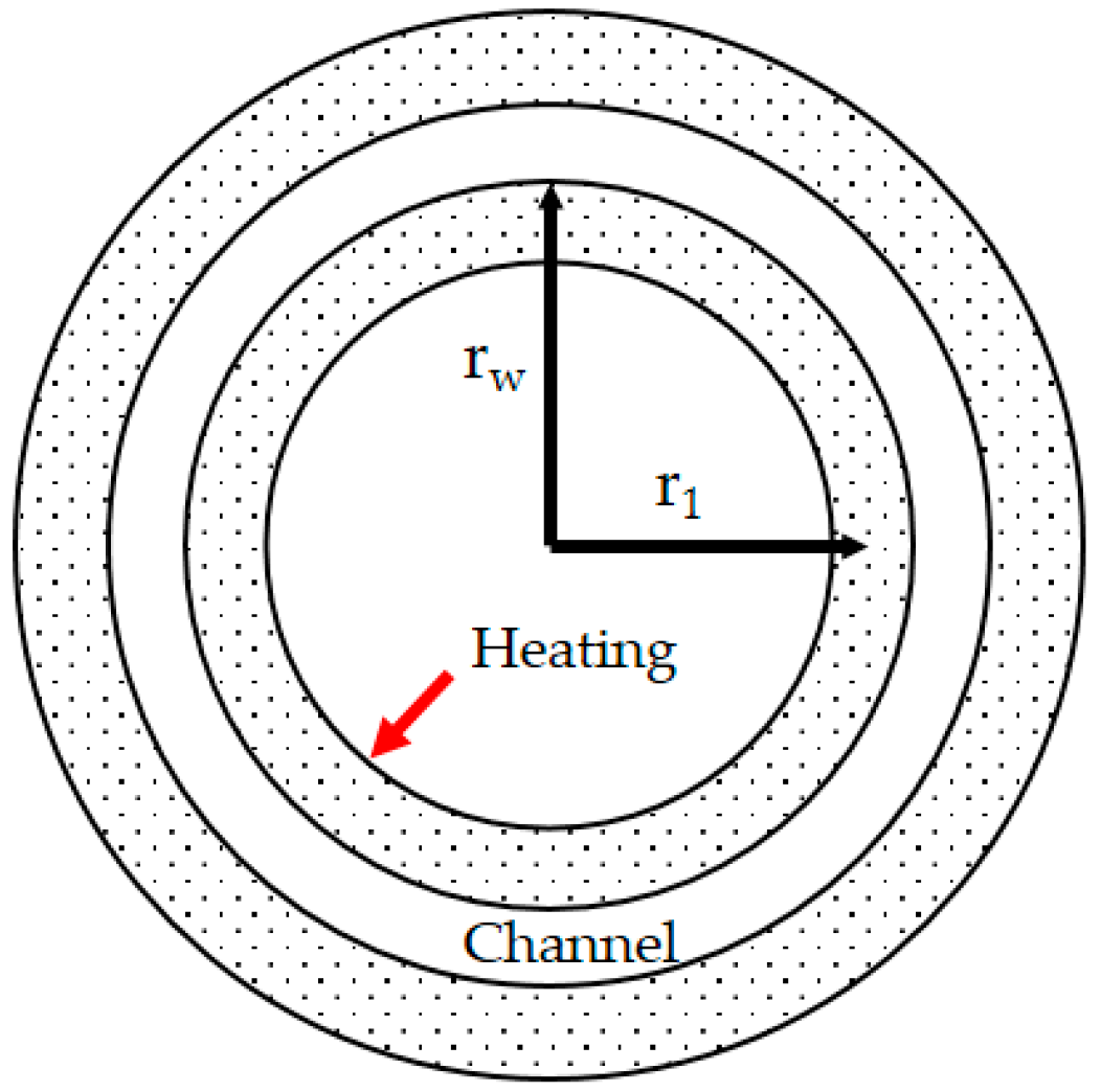
2.1. Basic Considerations to Obtain Average Nusselt Number

For obtaining the average Nusselt number through the thermal hydraulics experiment, the Equation (1) could be used. Here, Nu is the Nusselt number, Dh is the hydraulic diameter; λf is the thermal conductivity of coolant at bulk temperature; h is the convective heat transfer coefficient. q w is the wall-to-fluid heat flux; Tw is the temperature at the coolant-contacting wall; Tf is the bulk temperature of coolant. Once the geometry is given, the Dh is known. The unknowns that have to be derived from measured data are λf, q w , Tw, and Tf. q w can be calculated approximately by Equation (2), where λs is thermal conductivity of steel. Tf can be obtained approximately by Equation (3). Where Tinlet is coolant inlet temperature, Q(x) is the integrated power up to location x, cp is the specific heat of the coolant, and m ˙ is the mass flow rate. The λf could be obtained from literature data, once the bulk temperature is known. Tw can be obtained by Equation (4). T1 is a measured thermocouple temperature, r1 is the radius, at which place the thermocouple is installed, rw is the radius of inner surface of the annular channel, see Figure 2.
N u = D h λ f * h = D h λ f * q w T w T f
q w = λ s * d T d x
T f ( x ) = T i n l e t + Q ( x ) c p * m ˙
T w = T 1 | q w λ s * r w * ln ( r w r 1 ) |

2.2. Upscaling

The HELOKA facility offers a suitable DEMO-relevant testing range. HELOKA operates at temperatures ranging from room temperature to 550 °C, pressure ranging from 4 to 9.2 MPa, mass flow rate ranging from 20 g/s to 1400 g/s [15]. The pressurized helium coolant of the HCPB blanket has the nominal inlet/outlet of 300/520 °C. The mass flow rate per fuel-breeder pin in the breeder zone of HCPB blanket ranges from about 15 g/s to 23 g/s. To facilitate the measurement of temperature and controlling of mass flow rates, upscaling is needed, in which the same range of Reynolds number (Re), Péclet number (Pe), and the dimensionless heating rate q+ [16] are kept. Pe is equal to the multiplication of Re to Prandtl number (Pr). The Pr of helium is almost constant, therefore, only Re and q+ are the relevant parameters for upscaling. The definition of q+ is shown in Equation (5) where Across is the cross-section area of the channel, Q is the heating power, Aheat is the heating surface area.
q + = Q m ˙ * c p * T i n l e t A c r o s s A h e a t = q w ( m ˙ / A c r o s s ) * c p * T i n l e t
The nominal Re number in the annular channel of the HCPB blanket breeder zone ranges from 4000 to 5900. A wider range of Re (4000, 6000, 8000, and 10,000) was planned to cover any fluctuation in the mass flow rate in the HCPB blanket. The maximum heat flux from the ceramic breeder side to the annular coolant is about 10 times higher than that from Be12Ti block. Therefore, in the mockup only the inner side of the annular channel is heated to ease manufacturing and assembly efforts. The dimensionless heating rate, q+, of the HCPB breeder zone from ceramic breeder side to coolant in the annular channel ranges from 0.0002 via 0.0003, 0.0004, and 0.0005 to 0.00058. Therefore, the proposed q+ in this experiment are 0.0002, 0.0003, 0.0004, 0.0005, and 0.0006. Here, a comparison table of the heat flux at the same q+ at a selected Re number (Re = 4000, 21 g/s in HCPB and 25 g/s in mockup) is shown in Table 1.

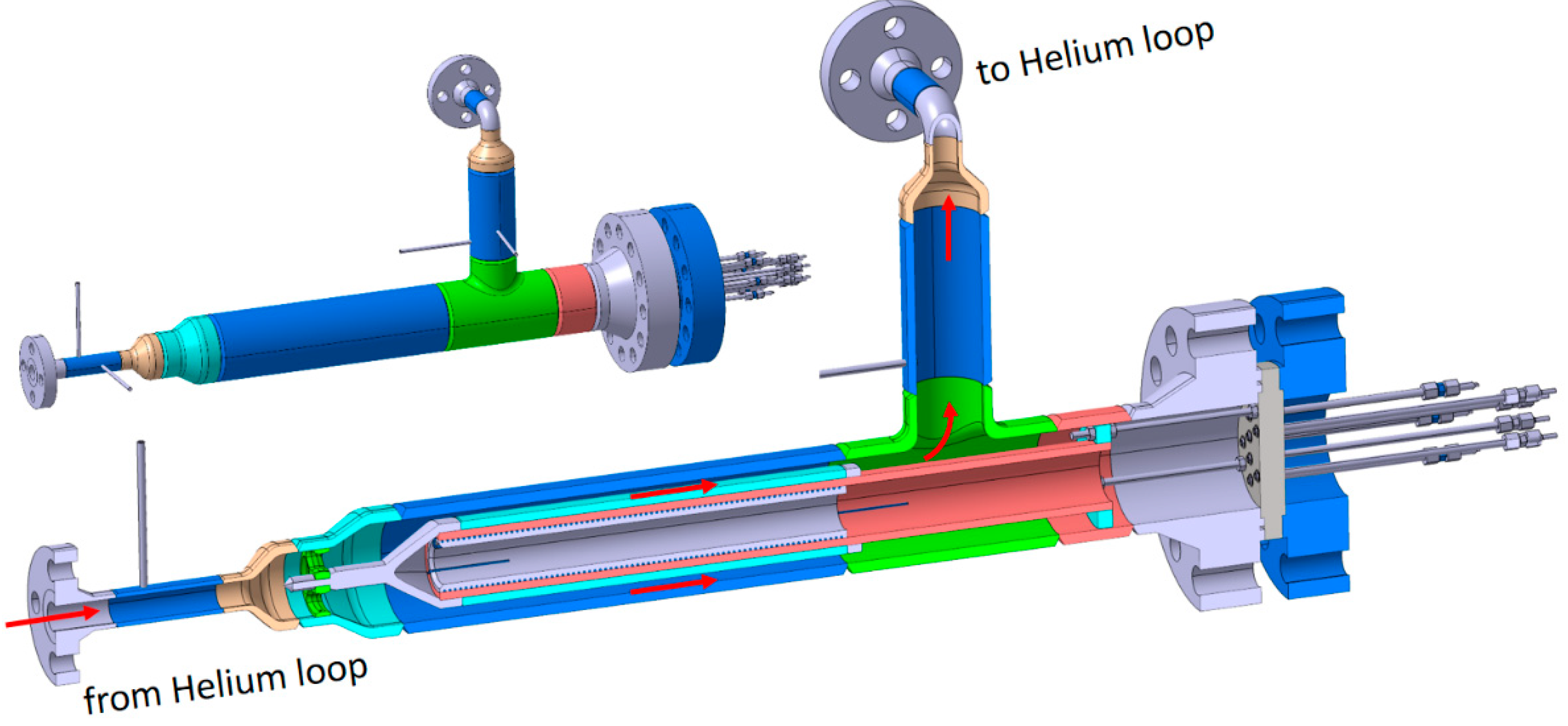
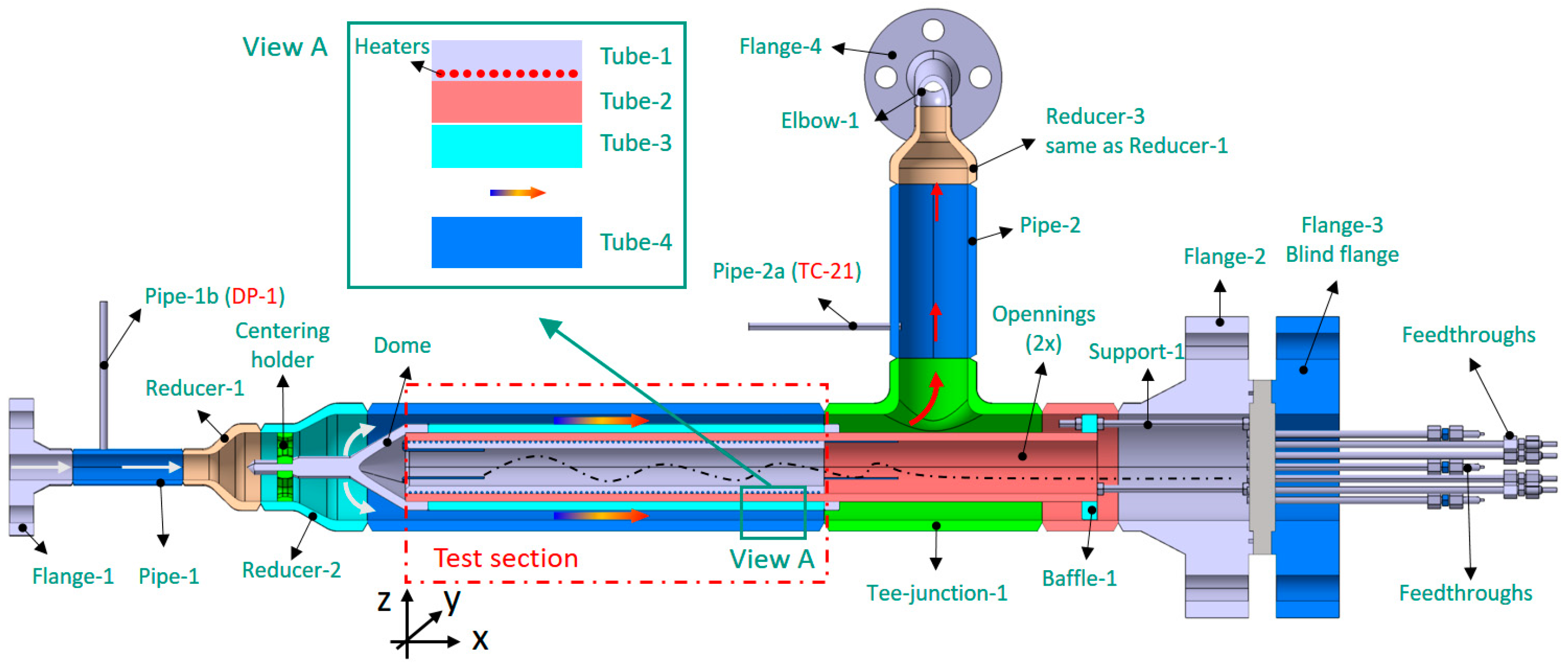
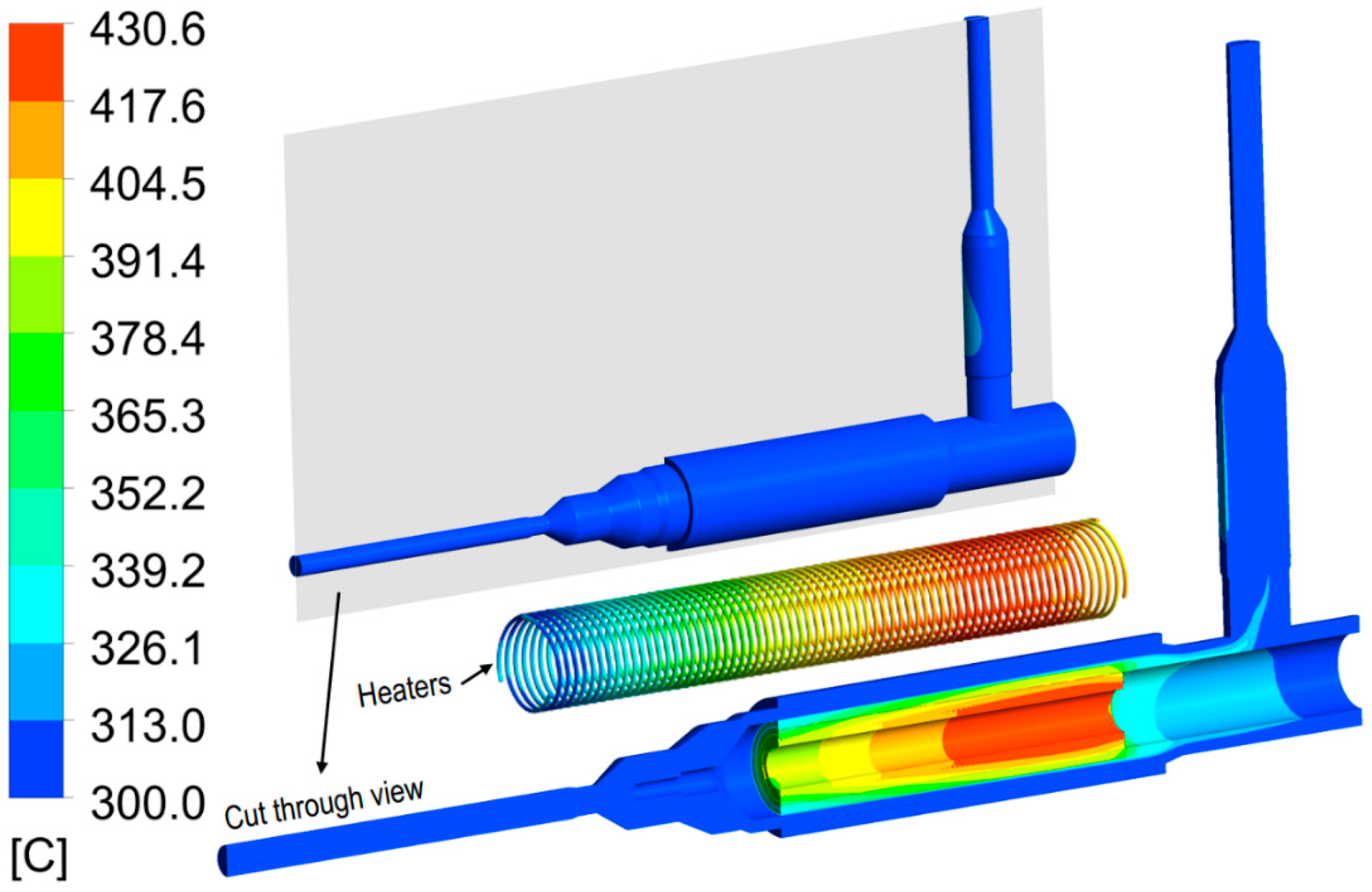
2.3. Design Description

After many iterations between designers and experimentalists, the design has been defined, as shown in Figure 3 and Figure 4, only pending confirmation from manufacturing partner. The mockup is connected to the HELOKA facility by using two flanges, facilitating the exchange of test sections. The mockup is heated through three-coiled, wire-form electric heaters, which are embedded into the grooves on the Tube-1 through brazing to ensure a good contact. The three electric heaters are identical and each can have a maximum heating power of 2000 W. The maximum power needed in this experiment is expected to be about 4000 W. The electric heaters will work at lower than the maximum heating capacity to optimize their lifetime.
In order to test the heat transfer enhancement of different roughness conditions on the surface of the annular channel, the mockup is designed in a way to make sure that the Tube-3 is exchangeable. Different roughness profiles were manufactured on the outer surfaces of different versions of Tube-3 that can be consecutively integrated into the mockup.
Tube-2 acts as the tube carrier for the Tube-1 (for heaters) and Tube-3 (for roughness). There are grooves for the three wire-form electric heaters. After winding into the grooves on Tube-1, the heaters are then brazed with Tube-1 and Tube-2. The Tube-3 is attached to Tube-2 using tack welding, which allows the Tube-3 to be dismantled from the Tube-2. At the upstream region, there is a cover-dome for guiding the coolant to flow into the annular channel formed by Tube-3 and Tube-4. Now, the Tube-1, Tube-2, and Tube-3 are bundled together, thereafter called insert-tubes. The region containing the tubes Tube-1, Tube-2, Tube-3, and Tube-4 is also called the test section. The outer contour of the mockup is driven by the dimension of Tube-4 (DN 150-120), which was determined using the above-mentioned upscaling methods. The Flange-1 is used to connect the mockup to the helium loop, whose pipe size is smaller than Tube-4. Therefore, two reducers are used to connect the Flange-1 to Tube-4. Tube-4 is then connected with a T-junction. The 90° branch is welded to Pipe-2 for returning the flow to the helium loop (see Figure 4). Again, a reducer (Reducer-3) is used for the transition of differently sized pipes. Between the Reducer-3 and the Flange-4, an elbow is used for accommodating thermal expansion. The straight branch of the T-junction is for facilitating the exchange of the insert-tubes and the feedthroughs of the electric heaters and thermocouples (TCs) through the Flange-2. These feedthroughs are needed for ensuring the tightness of mockup. The insert-tubes are connected by three evenly spaced support rods to a thick circular plate between the Flange-2 and Flange-3. The Flange-2 has an outer diameter of 395 mm. The total horizontal length from the inlet flange (Flange-1) to the end-tip of feedthrough is about 2080 mm. The vertical height of the mockup is about 898 mm. The total mass of this mockup (without considering isolation) is about 362 kg. The insert-tubes, which are planned to be exchanged during the experimental campaign, have a mass of about 67 kg.
The nominal dimensions of the 4 tubes at the test section is shown in Table 2. It is desired that, during the manufacturing, a small fabrication tolerance will be maintained.
Based on the previous study of Shah and Bhatti [17], the flow regime in ducts can be classified into three categories: (1) hydraulically smooth regime, (2) transition regime, and (3) fully rough regime. Shah and Bhatti [17] have proposed correlations for the Nusselt number for the different flow regime. The classification is based on the value of roughness Reynolds number e+, defined as follows:
e + = Re * e D h * f 8
where, Re is Reynolds number, e sand-grain roughness, Dh the hydraulic diameter, f Darcy friction factor.
0 e + < 5   Hydraulically   smooth   regime
5 e + < 70   Transition   regime
e + 70   Fully   rough   regime
Three different surface roughness conditions are proposed to be tested following the above-mentioned flow regime classifications. For the hydraulically smooth regime, the normally manufactured surface with an Rz of about 10 µm, where Rz is the difference between the tallest peak and the deepest valley in the surface. Different roughness sets are to be tested to select the most optimized ones. The roughness sets on Tube-3 are shown in Table 3. The roughness Re of different roughness sets are shown in Table 4.

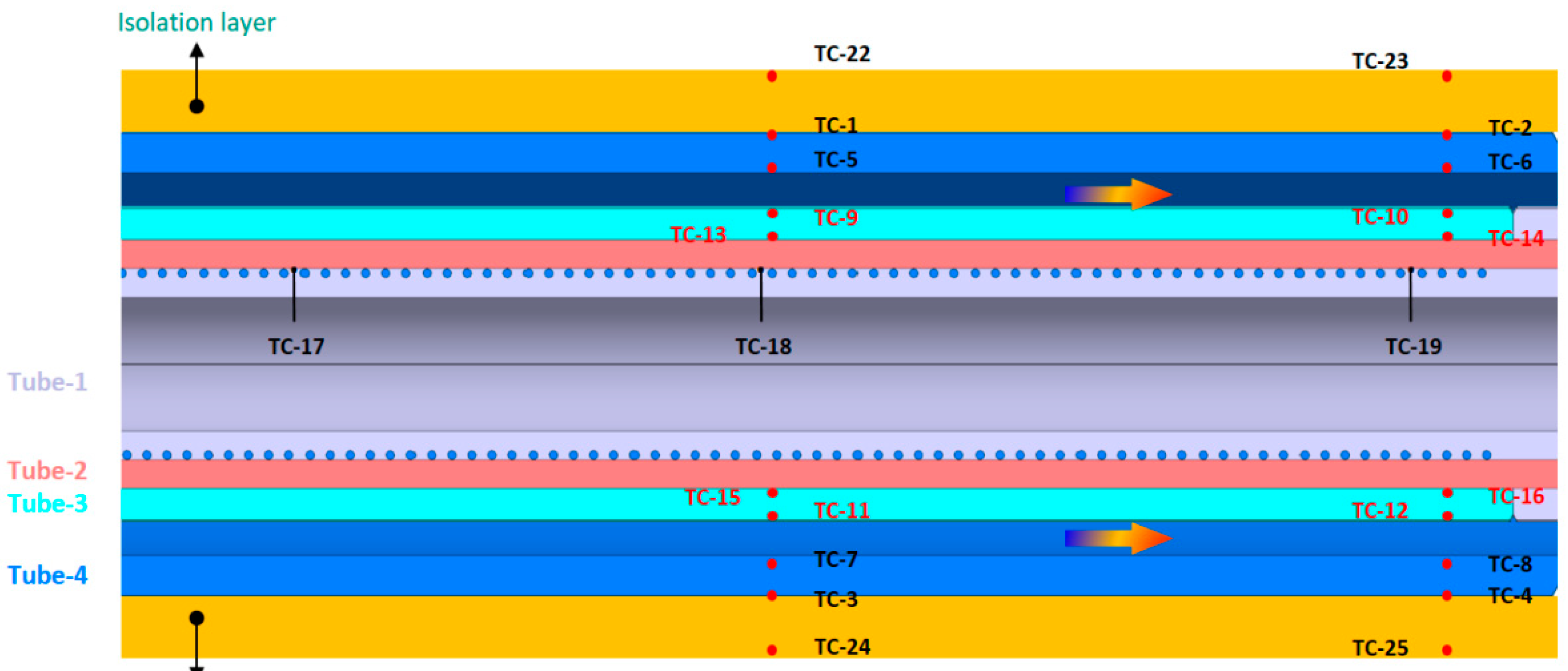
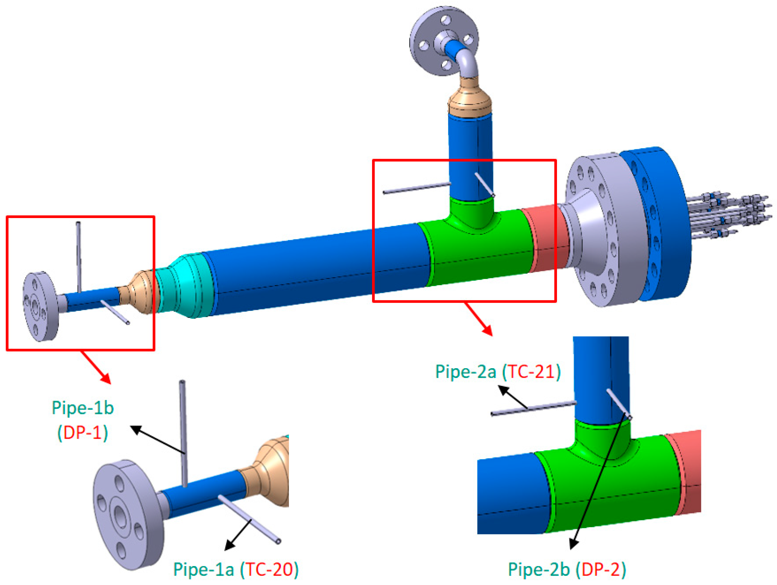
3. Measurement of the Mockup

To obtain the unknown quantities in Section 2, many temperature measures are needed. The locations of the thermocouples in the test section are displayed in Figure 5. The whole mockup is installed into a robust metallic tank, which is exposed to environment air through small, opened windows. By doing this, the staff would not be affected in case of a breakage of the mockup. In order to minimize the heat loss from the mockup to the environment, all the mockup parts are wrapped in 4-layer thick isolation layers (totally about 115 mm thick, not scaled in Figure 5). At the test section, two axial locations are chosen to measure the temperature in order to obtain information both at the axial-half length and at the proximity of the full length of the test section. To be redundant on the measure, pairs of thermocouples are used at the same axial and radial location, e.g., TC-1 pairing with TC-3. The number of thermocouples is also limited by the maximum number that the facility can accommodate. The thermocouples TC-1 to TC-8 are on the Tube-4 for measuring the temperature at the middle and on the end of Tube-4 to determine the heat flow from the mockup to the isolation layer. The thermocouples TC-22 to TC-25 are attached on the outer-surface of the isolation layers; together with TC-1 to TC-4, these TCs are used to obtain the heat loss from the mockup to the environment. The thermocouples TC-9 to TC-16 are used to determine the heat flux from the solid to the coolant. The thermocouples TC-17 to TC-19 are used for monitoring the temperatures of three electric heaters.
Upstream of the test section, there are two small pipes (called Pipe-1a and Pipe-1b) for accommodating the thermocouple (TC-20) and pressure tap (DP-1). At the downstream region of the test section, there are also thermocouple (TC-21) and pressure tap (DP-2). The locations of these thermocouples and pressure taps are depicted in Figure 6. Since we are more interested in the temperature measure in this work, the TC-20 and TC-21 are placed closer than DP-1 and DP-2 to the test section. A differential pressure sensor is connected to the mock-up inlet (Pipe-1b) and outlet (Pipe-2b) via two pressure taps DP-1 and DP-2.
For the safety of the mockup and the HELOKA facility, several safety measurements needed to be implemented to protect the electric heaters from overheating and damaging the mockup and the HELOKA facility. The thermocouples TC-17 to TC-19 are attached to the safety circuit, with a temperature limit of 500 °C. The thermocouple TC-6 located on the inner surface of Tube-6 and the thermocouple TC-21 for measuring the coolant temperature at the outlet are used for triggering safety signals, with 400 °C as the corresponding temperature limit. Once any of the temperatures on these thermocouples exceeds the above-defined temperature limits (500 °C for TC-17 to TC-19 and 400 °C for TC-6 and TC-21), the electric heaters will be switched off automatically.

4. Test Matrix

There are 7 roughness sets. The runs are grouped following the Reynolds numbers, which are 4000, 6000, 8000, and 10,000. The heating powers are calculated by the corresponding dimensionless heating rate q+ (ranging from 0.0002, 0.0003, 0.0004, 0.0005, and 0.0006) using Equation (5), which represents the q+ range in the HCPB breeder zone [1,18]. Therefore, in total, there are 140 runs. The inlet temperature of the coolant is always set at 300 °C.

5. Categorization of the Mockup following the European Union Pressure Equipment Directive

Since the mockup is a pressure equipment, the mockup has to conform to the requirements of European Union Pressure Equipment Directive 2014/68/EU. There are several steps to determine the category of pressure equipment following the Directive 2014/68/EU.
Step 1: Grouping of the fluid.
Step 2: Check if it is required to meet the essential safety requirements according to Annex I of the Directive 2014/68/EU.
Step 3: Assignment of the category (Cat. I to Cat. IV), based on: Type of pressure equipment (vessel or piping); state of aggregation of the fluid; Fluid group of the fluid and design data (Product of pressure and volume or pipe size).
Following the above-mentioned steps and the instructions in the Directive 2014/68/EU, the pressurized helium is not hazardous; therefore, it is grouped into Fluid II/gaseous. As pressure equipment, the mockup is required to meet the essential safety requirements. Based on the features of the mockup, the mockup can be considered as vessel or as piping. It is decided to consider the mockup as piping pressure equipment. Finally, the mockup is assigned to pressure equipment Cat. III module G. The thickness of the pressure-bearing parts is determined following the harmonized European Norm of metallic industrial piping EN 13480 [19] and pressure vessel EN 13445 [20].
The maximum operating temperature allowed in HELOKA facility is 550 °C and the operating pressure is 8 MPa. Following the norms, the calculation pressure should be 9.2 MPa, 115% of the operating pressure, to account uncertainty. According to the norm EN 13445, the strength condition and geometrical condition (e.g., minimum thickness) should be met. Using the professional European Norm-conforming software FEST [21], the required minimal effective thickness of the tube is 8.6 mm; the required maximum ratio of effective thickness to outer diameter is 0.16. The selected tube size is with 168.3 mm as outer diameter and with a thickness of 12 mm.

6. Performance Analysis

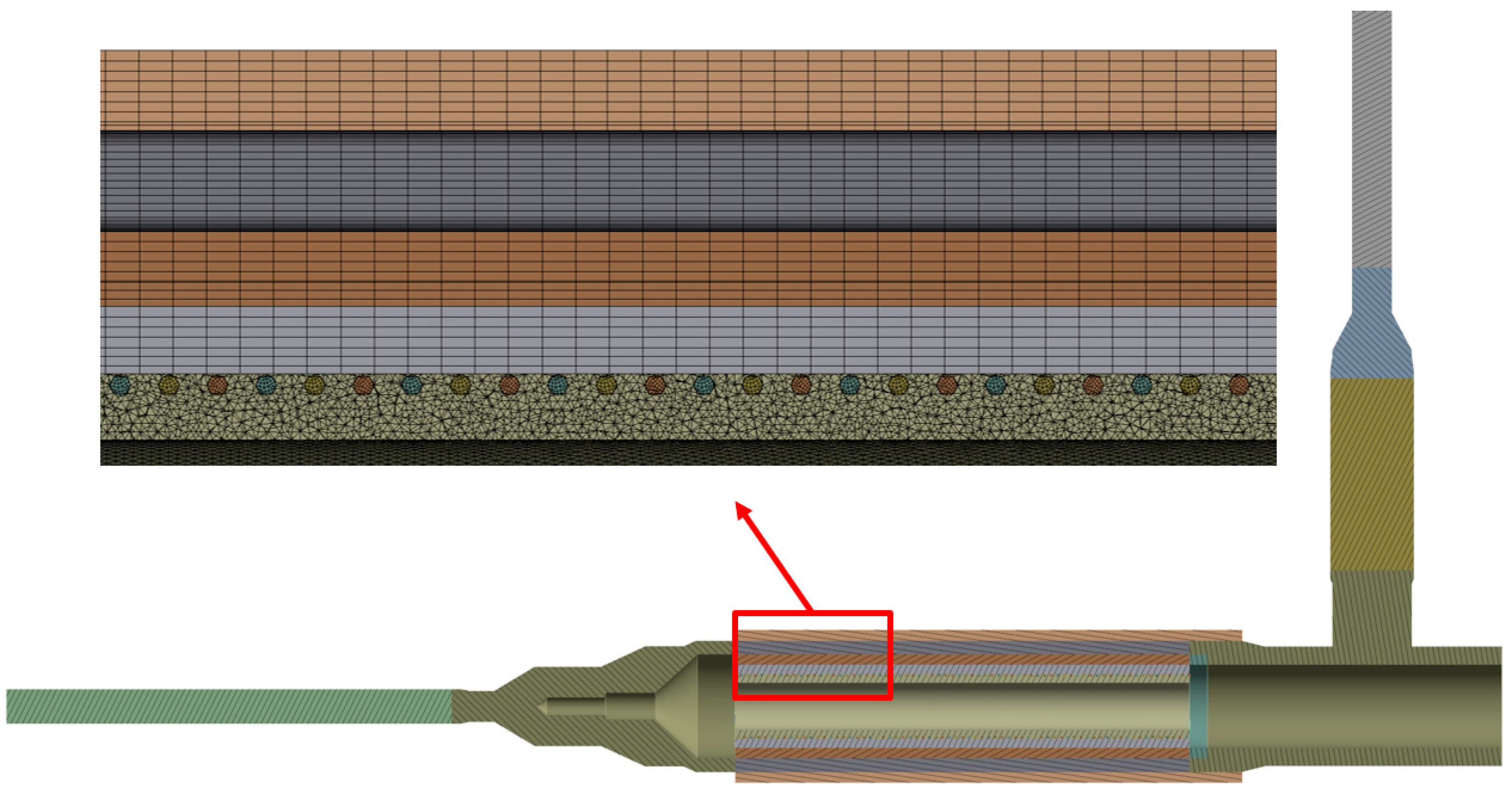
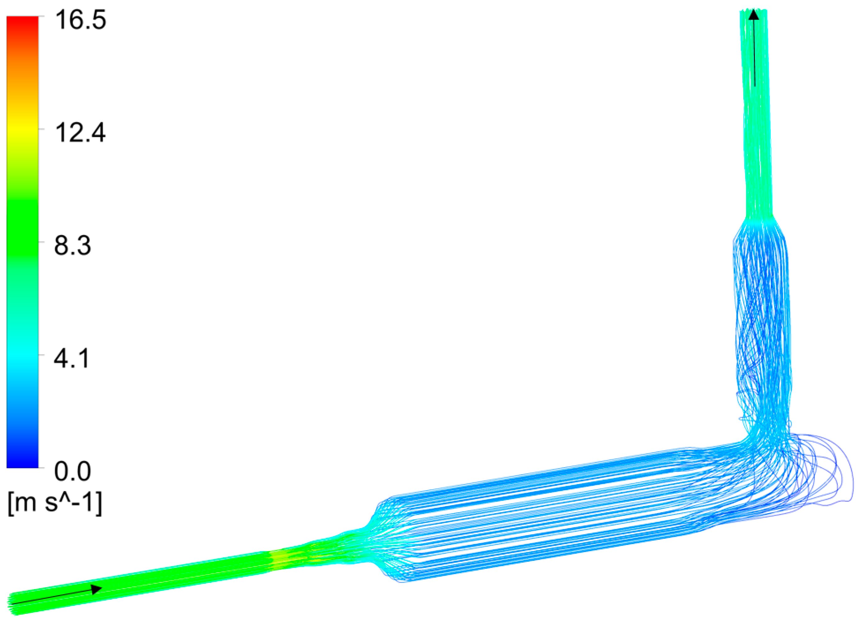
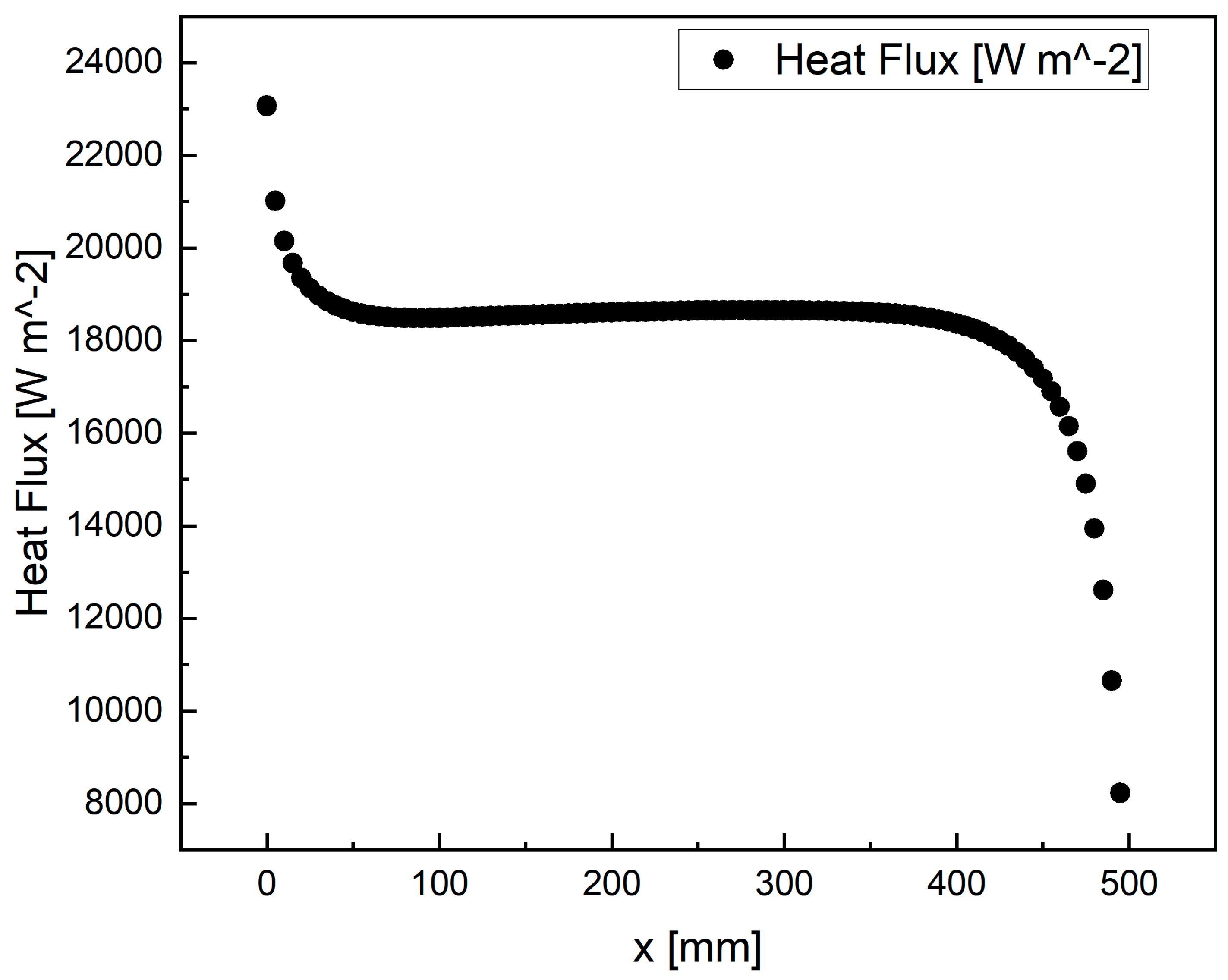
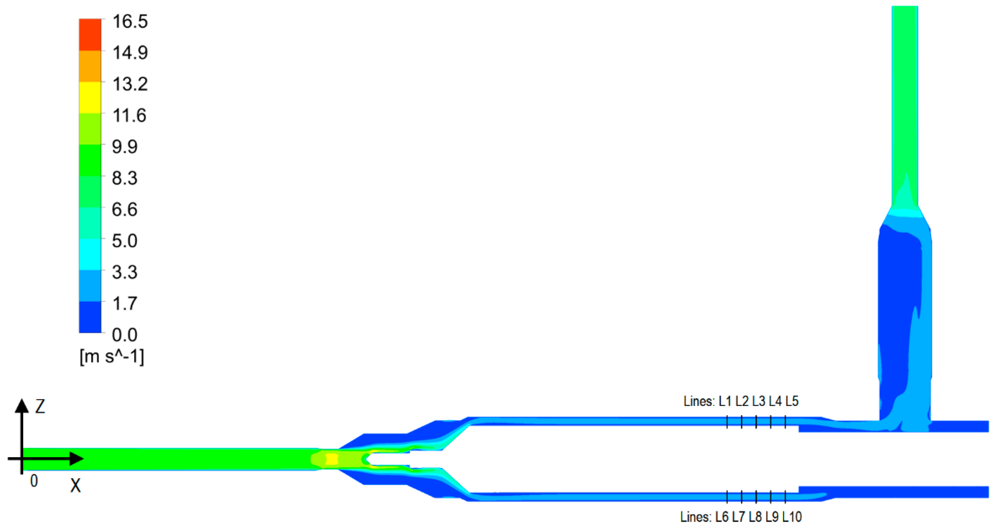
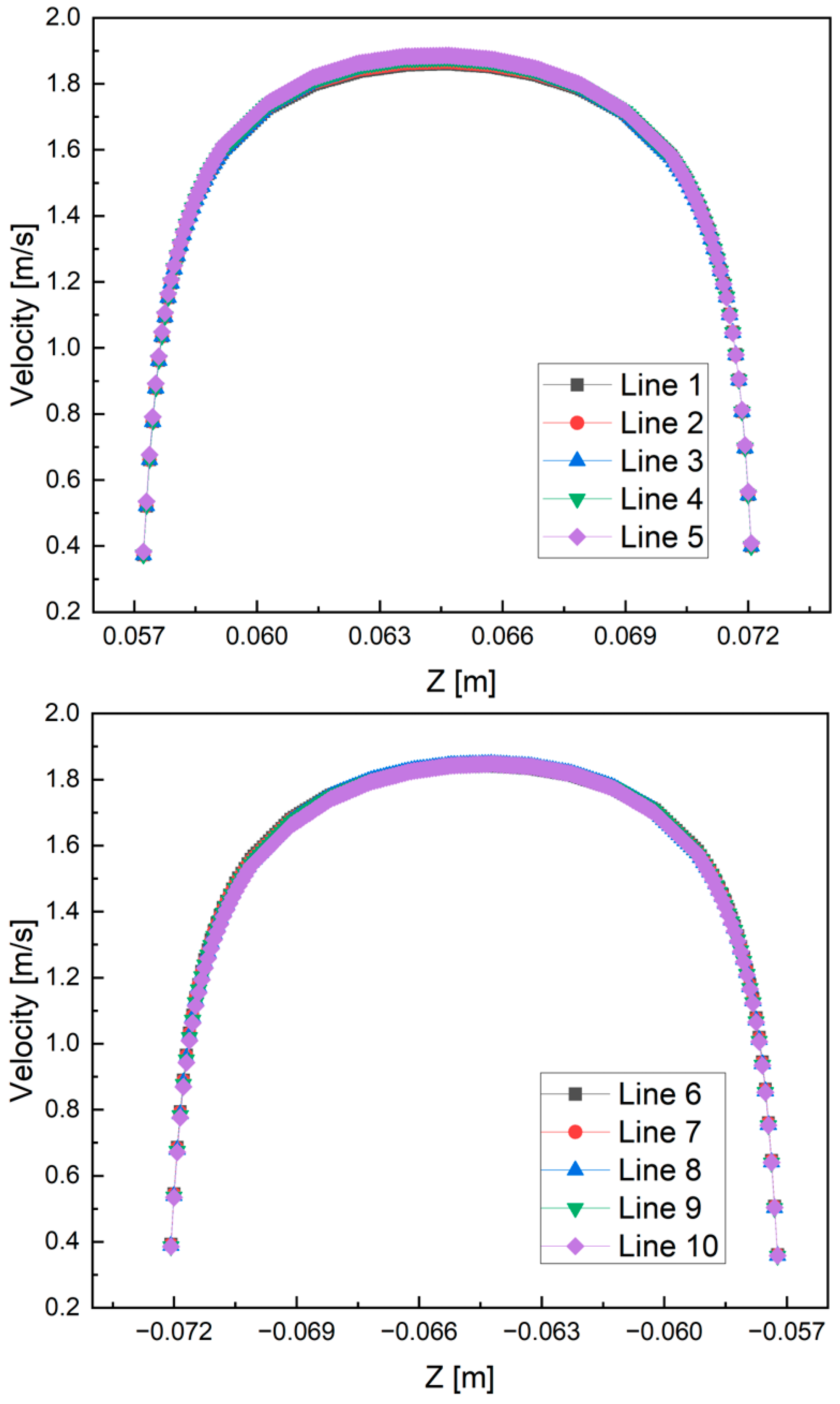
6.1. Thermofluid-Dynamic Analysis

To reduce meshing and computation time, only critical regions had been modelled in the 3D conjugated CFD thermofluid-dynamic analyses to assess the temperature fields at these critical regions and the flow distribution. The critical regions include the fluid domain from the inlet to outlet of the mockup, the electric heaters, the Tube-1, Tube-2, Tube-3, and Tube-4. The mesh of the model is shown in Figure 7, done by using ANSYS Meshing. Besides the wire electric heaters and Tube-1, all the other parts were meshed by structured hexagonal mesh. In the fluid domain, there were 10 layers of boundary layers. And the mesh size is fine enough to ensure that the y+ is about 1. Totally, there are about 50 million elements. The CFD software CFX was used for the calculations.
The solid structure was made of stainless-steel SS 316, whose physical properties were provided by the supplier and are temperature-dependent. The helium properties were taken from the NIST [22] and implemented into the CFX setting-up as temperature- and pressure-dependent.
Many CFD simulations were done. Here, only a representative case is shown, with a mass flow rate of 64 g/s and with a q+ of 0.0006 (corresponding to a total heating power of 3370 W). The thermal contact conductance (TCC) between Tube-2 and Tube-3 is calculated to be about 2400 W/(m2 K) assuming a stagnant helium gap of 0.1 mm.
The velocity streamline of the coolant is shown in Figure 8. The temperature contour of the mockup is shown in Figure 9. The hotspots are located at the heaters and the Tube-1, which surrounds the heaters. Maximum temperature of the tube is 430.6 °C, well below the allowable operating temperature 550 °C. The total pressure drop between inlet and outlet is calculated to be about 390 Pa.
The average heat flux from Tube-3 towards coolant is shown in Figure 10. The heat flux at heating region between 50 mm and 400 mm is uniform. It can be seen that there are entrance and exit effects on the heat flux distribution, which should be taken into account when post-processing the experimental data in the future.
The velocity contour of the coolant is shown in Figure 11. The velocity profile of 10 lines crossing the annular channel (location of the 10 lines shown in Figure 11) approaching the end of the test section is shown in Figure 12. It can be seen that the flow profiles at different lines almost overlap. The velocity profile comparison at lines 4, 9, 5, and 10 is shown in Figure 13. It is observed that the flow there is not symmetric, probably because of the T-junction at the outlet.
As the contact between Tube-1 and Tube-2 is ensured via brazing, a perfect contact between them is assumed. The TCC between different tubes will influence the heat transfer between them. Therefore, for the sake of model robustness, a scoping study varying the TCC values between Tube-2 and Tube-3 should be done. The scoping study considers four different TCC values between Tube-2 and Tube-3: 500, 1000, 1500, and 2000 W/(m2 K), all below the nominal value 2400 W/(m2 K). The temperature fields of the four cases are shown in Figure 14. It can be seen that the maximum temperature 467.6 °C on the mockup occurs at TCC = 500 W/(m2 K), which implies that the mockup will be safe (Tmax < 550 °C), even with a very low TCC.

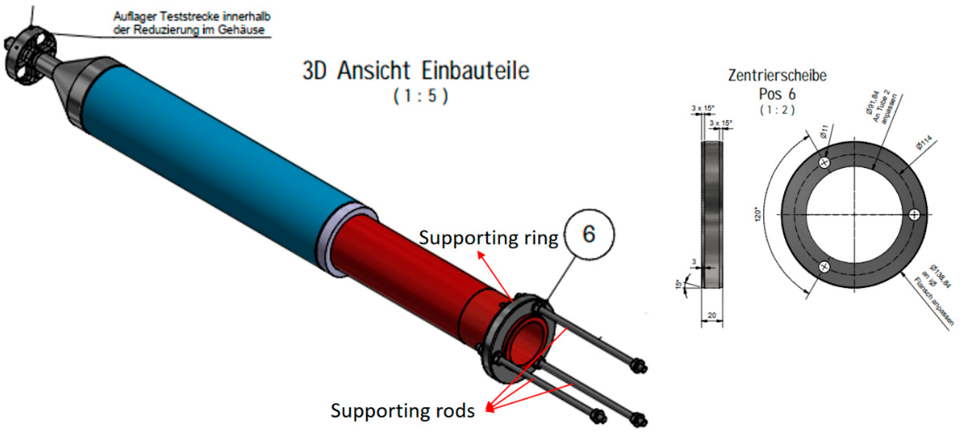
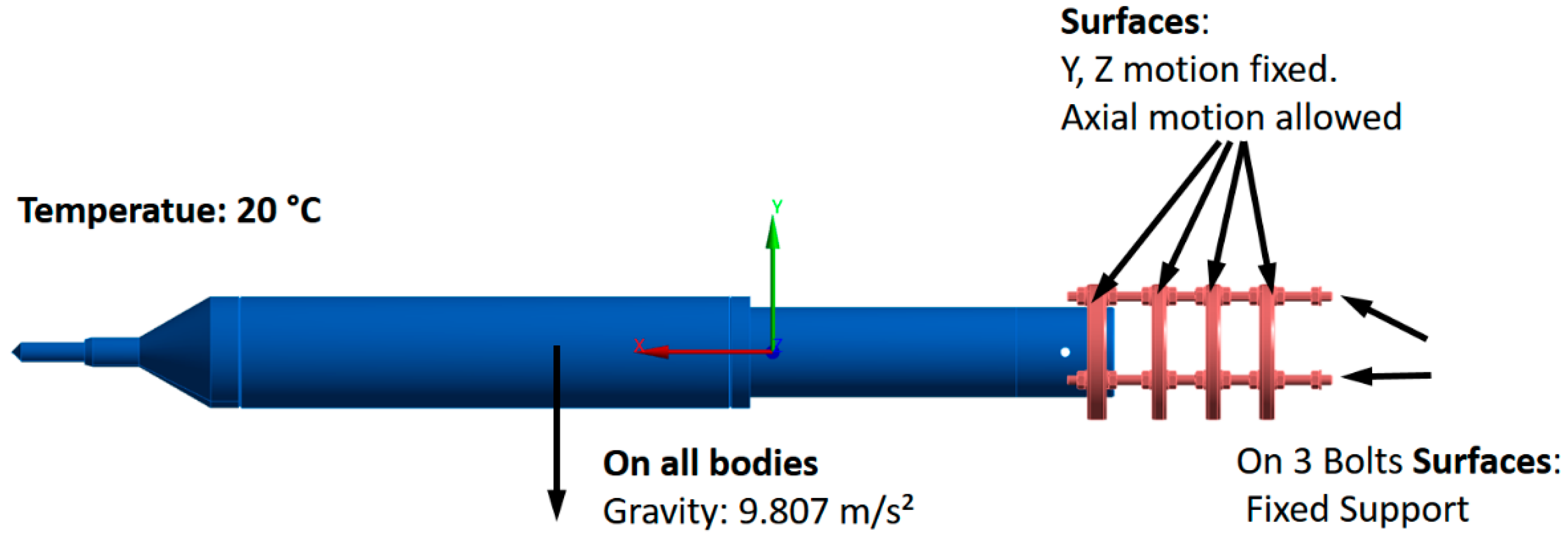
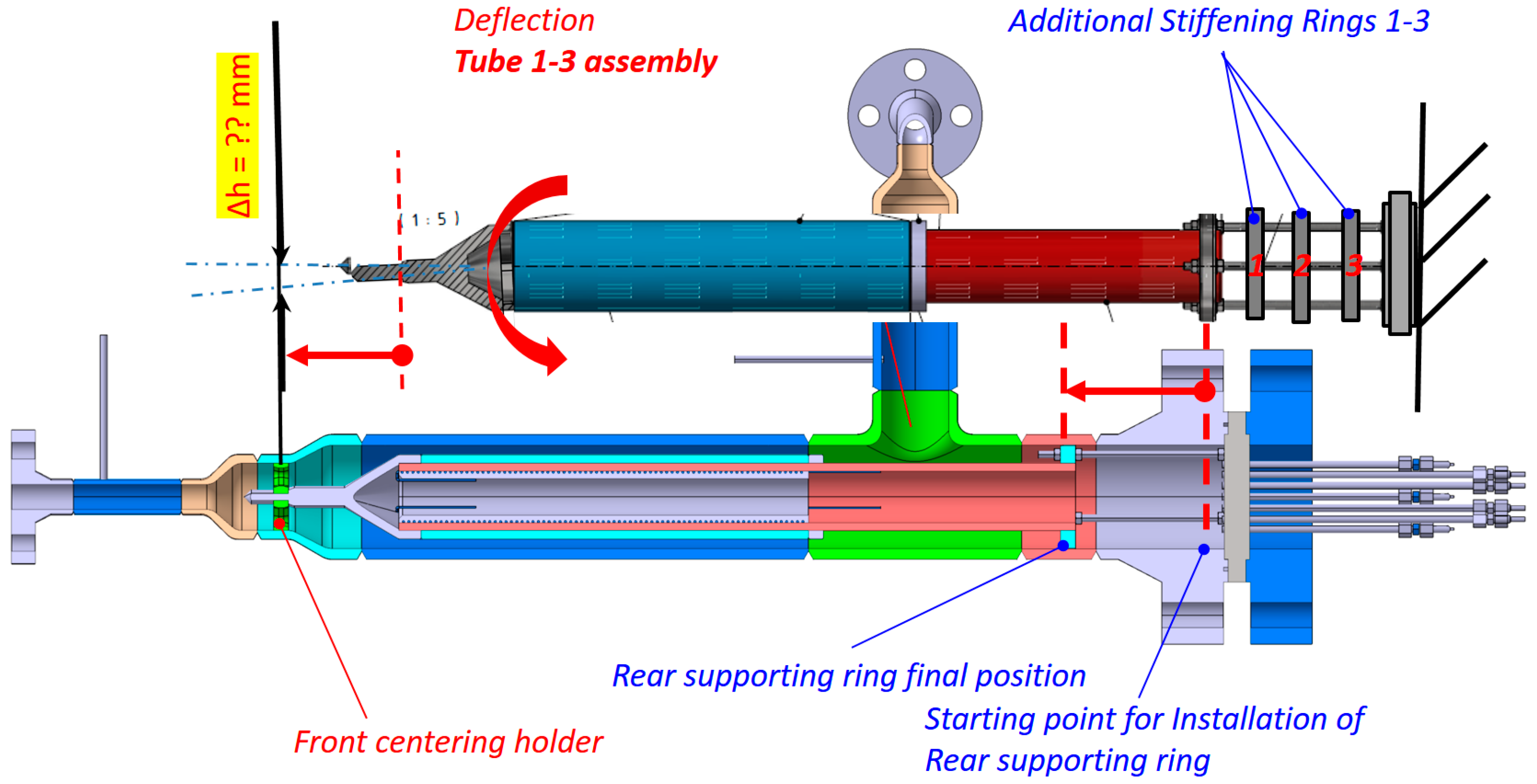
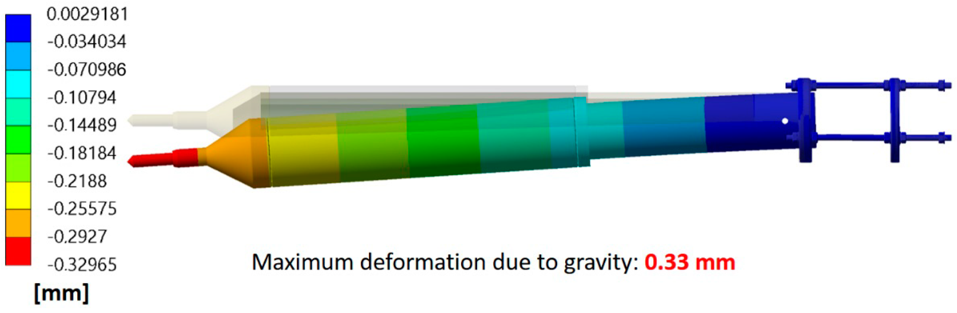
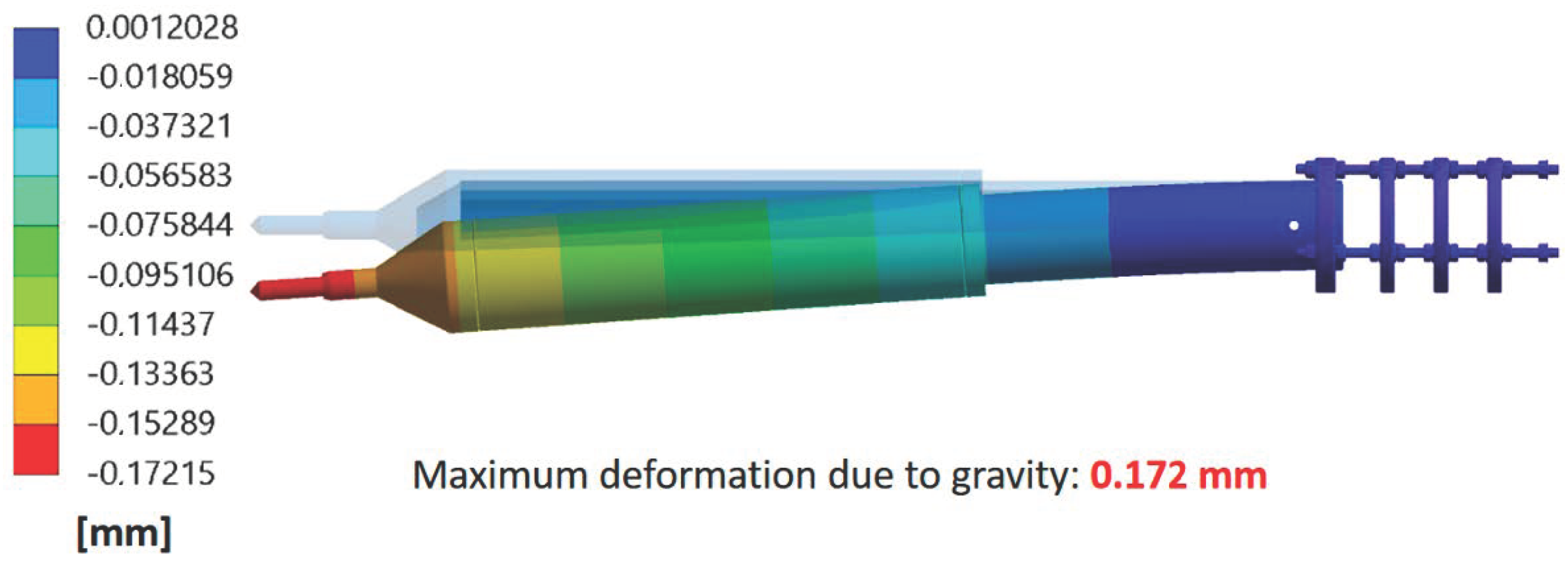
6.2. Determining the Number of Stiffening Rings

In order to hold the tube insert in position, its rear part is supported by the supporting rods connected via the supporting ring, see Figure 15. In the original design, as shown in Figure 3 and Figure 4, there is only one supporting ring. However, after discussion with the manufacturing partner, it was suggested to have additional stiffening rings for reinforcement. Therefore, FEM analysis was done to check the deflection of the front part of the tube insert due to self-weight. Two cases were studied. The first one (case 1) with one additional stiffening ring, the second one (case 2) with three additional stiffening rings. The boundary conditions for case 2 are shown in Figure 16. Similar boundary conditions for case 1 were used.
The deflection of the tube insert is shown in Figure 17.
The resulting deformations for case 1 and case 2 are respectively shown in Figure 18 and Figure 19.
It can be seen that with three additional stiffening rings, the deformation due to self-weight is smaller. To be conservative, case 2 is chosen for the final design.

7. Conclusions and Outlook

In this article, the design of a breeder zone mockup of the EU DEMO HCPB breeding blanket has been presented. The analyses show that the temperature field and flow distribution are within expected range. The design of the pressure-bearing parts is checked with the harmonized European Standard EN 13480, hence ensuring the conformity of the design with the latest European Union Pressure Equipment Directive 2014/68/EU. Nevertheless, before manufacturing, the design shall be verified by a notified body, which is the natural follow-up step. Once manufactured, the mockup will be tested in the high-pressure, high temperature helium facility (HELOKA) at Karlsruhe Institute of Technology.

Author Contributions

Conceptualization: G.Z., J.R., F.A.H., A.A.-S., M.L., F.A., G.S. and F.S.; investigation: G.Z. and J.R.; resources, F.A.H.; writing—original draft preparation: G.Z.; visualization: G.Z.; supervision: G.Z.; project administration: G.Z. and J.R.; funding acquisition: F.A.H. All authors have read and agreed to the published version of the manuscript.

Funding

This work has been carried out within the framework of the EUROfusion Consortium, funded by the European Union via the Euratom Research and Training Programme (Grant Agreement No 101052200—EUROfusion). Views and opinions expressed are, however, those of the author(s) only and do not necessarily reflect those of the European Union or the European Commission. Neither the European Union nor the European Commission can be held responsible for them.

Institutional Review Board Statement

Not applicable.

Informed Consent Statement

Not applicable.

Data Availability Statement

The data are not publicly available due to ongoing research based on the current data.

Conflicts of Interest

The authors declare no conflict of interest. The funders had no role in the design of the study; in the collection, analyses, or interpretation of data; in the writing of the manuscript, or in the decision to publish the results.

References

  1. Hernández, F.A.; Pereslavtsev, P.; Zhou, G.; Kang, Q.; D’Amico, S.; Neuberger, H.; Boccaccini, L.V.; Kiss, B.; Nádasi, G.; Maqueda, L.; et al. Consolidated design of the HCPB Breeding Blanket for the pre-Conceptual Design Phase of the EU DEMO and harmonization with the ITER HCPB TBM program. Fusion Eng. Des. 2020, 157, 111614. [Google Scholar] [CrossRef]
  2. Arena, P.; Del Nevo, A.; Moro, F.; Noce, S.; Mozzillo, R.; Imbriani, V.; Giannetti, F.; Edemetti, F.; Froio, A.; Savoldi, L.; et al. The DEMO Water-Cooled Lead–Lithium Breeding Blanket: Design Status at the End of the Pre-Conceptual Design Phase. Appl. Sci. 2021, 11, 11592. [Google Scholar] [CrossRef]
  3. Federici, G.; Boccaccini, L.; Cismondi, F.; Gasparotto, M.; Poitevin, Y.; Ricapito, I. An overview of the EU breeding blanket design strategy as an integral part of the DEMO design effort. Fusion Eng. Des. 2019, 141, 30–42. [Google Scholar] [CrossRef]
  4. Pereslavtsev, P.; Hernández, F.A.; Zhou, G.; Lu, L.; Wegmann, C.; Fischer, U. Nuclear analyses of solid breeder blanket options for DEMO: Status, challenges and outlook. Fusion Eng. Des. 2019, 146, 563–567. [Google Scholar] [CrossRef]
  5. Zhou, G.; Kang, Q.; Hernández, F.A.; D’Amico, S.; Kiss, B. Thermal hydraulics activities for consolidating HCPB breeding blanket of the European DEMO. Nucl. Fusion 2020, 60, 096008. [Google Scholar] [CrossRef]
  6. Hernández, F.A.; Pereslavtsev, P.; Zhou, G.; Kiss, B.; Kang, Q.; Neuberger, H.; Chakin, V.; Gaisin, R.; Vladimirov, P.; Boccaccini, L.V.; et al. Advancements in the Helium-Cooled Pebble Bed Breeding Blanket for the EU DEMO: Holistic Design Approach and Lessons Learned. Fusion Sci. Technol. 2019, 75, 352–364. [Google Scholar] [CrossRef]
  7. Ilić, M.; Messemer, G.; Zinn, K.; Meyder, R.; Kecskes, S.; Kiss, B. Experimental and numerical investigations of heat transfer in the first wall of Helium-Cooled-Pebble-Bed Test Blanket Module—Part 2: Presentation of results. Fusion Eng. Des. 2015, 90, 37–46. [Google Scholar] [CrossRef]
  8. Ilić, M.; Schlindwein, G.; Meyder, R.; Kuhn, T.; Albrecht, O.; Zinn, K. Experimental investigations of flow distribution in coolant system of Helium-Cooled-Pebble-Bed Test Blanket Module. Fusion Eng. Des. 2016, 103, 53–68. [Google Scholar] [CrossRef]
  9. Ruck, S.; Köhler, S.; Schlindwein, G.; Arbeiter, F. Heat transfer and pressure drop measurements in channels roughened by variously shaped ribs on one wall. Exp. Heat Transf. 2017, 31, 334–354. [Google Scholar] [CrossRef]
  10. Hernández, F.; Kolb, M.; Annabattula, R.; Weth, A.V. Construction of PREMUX and preliminary experimental results, as preparation for the HCPB breeder unit mock-up testing. Fusion Eng. Des. 2014, 89, 1257–1262. [Google Scholar] [CrossRef] [Green Version]
  11. Zeile, C.; Abou-Sena, A.; Boccaccini, L.; Ghidersa, B.; Kang, Q.; Kunze, A.; Lamberti, L.; Maione, I.; Rey, J.; von der Weth, A. Conceptual design of a First Wall mock-up experiment in preparation for the qualification of breeding blanket technologies in the Helium Loop Karlsruhe (HELOKA) facility. Fusion Eng. Des. 2016, 109–111, 1335–1339. [Google Scholar] [CrossRef]
  12. Ghidersa, B.-E.; Gonfiotti, B.; Kunze, A.; Di Marcello, V.; Ionescu-Bujor, M.; Jin, X.Z.; Stieglitz, R. Experimental Investigation of a Helium-Cooled Breeding Blanket First Wall under LOFA Conditions and Pre-Test and Post-Test Numerical Analysis. Appl. Sci. 2021, 11, 12010. [Google Scholar] [CrossRef]
  13. Zhou, G.; Ghidersa, B.-E.; Hernández, F.A.; Kang, Q.; Neuberger, H. Design of Two Experimental Mock-Ups as Proof-of-Concept and Validation Test Rigs for the Enhanced EU DEMO HCPB Blanket. Fusion Sci. Technol. 2019, 75, 1016–1023. [Google Scholar] [CrossRef]
  14. Hernández, F.; Pereslavtsev, P.; Kang, Q.; Norajitra, P.; Kiss, B.; Nádasi, G.; Bitz, O. A new HCPB breeding blanket for the EU DEMO: Evolution, rationale and preliminary performances. Fusion Eng. Des. 2017, 124, 882–886. [Google Scholar] [CrossRef]
  15. Ghidersa, B.-E.; Ionescu-Bujor, M.; Janeschitz, G. Helium Loop Karlsruhe (HELOKA): A valuable tool for testing and qualifying ITER components and their He cooling circuits. Fusion Eng. Des. 2006, 81, 1471–1476. [Google Scholar] [CrossRef]
  16. Bankston, C.; McEligot, D. Turbulent and laminar heat transfer to gases with varying properties in the entry region of circular ducts. Int. J. Heat Mass Transf. 1970, 13, 319–344. [Google Scholar] [CrossRef]
  17. Shah, R.K.; Bhatti, M. Assessment of Correlations for Single-Phase Heat Exchangers. In Proceedings of the NATO Advanced Study Institute on Thermal-Hydraulic Fundamentals and Design of Two-Phase Flow Heat Exchangers, Povoa de Varzim, Portugal, 6–17 July 1987. [Google Scholar]
  18. Spagnuolo, G.A.; Boccaccini, L.V.; Bongiovì, G.; Cismondi, F.; Maione, I.A. Development of load specifications for the design of the breeding blanket system. Fusion Eng. Des. 2020, 157, 111657. [Google Scholar] [CrossRef] [Green Version]
  19. EN 13480-3:2017-12; Metallic Industrial Piping—Part 3: Design and Calculation. CEN: Brussels, Belgium, 2017.
  20. EN 13445-3:2014; Unfired Pressure Vessels—Part 3: Design. CEN: Brussels, Belgium, 2014.
  21. FEST. Lauterbach Verfahrenstechnik GmbH, Software und Engineering im Apparatebau und Anlagenbau. Available online: https://lv-soft.net/ (accessed on 18 July 2018).
  22. National Institute of Standards and Technology (NIST), Fluid Properties of Helium. Available online: https://webbook.nist.gov/cgi/cbook.cgi?Name=helium&Units=SI&cTG=on (accessed on 2 September 2019).
Figure 1. European DEMO HCPB blanket concept.
Applsci 13 02081 g001
Figure 2. Annular channel.
Applsci 13 02081 g002
Figure 3. CAD of mockup.
Applsci 13 02081 g003
Figure 4. Naming of mockup.
Applsci 13 02081 g004
Figure 5. TCs on test section.
Applsci 13 02081 g005
Figure 6. Thermocouples and pressure sensors upstream and downstream of test section.
Applsci 13 02081 g006
Figure 7. Mesh of the critical region of the mockup.
Applsci 13 02081 g007
Figure 8. Velocity streamline of the coolant.
Applsci 13 02081 g008
Figure 9. Temperature contour of the mockup.
Applsci 13 02081 g009
Figure 10. Average heat flux of Tube-3 towards coolant at the heated zone.
Applsci 13 02081 g010
Figure 11. Velocity contour.
Applsci 13 02081 g011
Figure 12. Velocity profile at lines 1–10.
Applsci 13 02081 g012
Figure 13. Velocity profile at lines 4 vs. 9 and 5 vs. 10.
Applsci 13 02081 g013
Figure 14. Temperature contours of the mockup of different TCC values.
Applsci 13 02081 g014
Figure 15. Supporting ring and rods.
Applsci 13 02081 g015
Figure 16. Boundary conditions case 2.
Applsci 13 02081 g016
Figure 17. Assembly of the tube insert.
Applsci 13 02081 g017
Figure 18. Deformation for one additional stiffening ring (case 1).
Applsci 13 02081 g018
Figure 19. Deformation for three additional stiffening rings (case 2).
Applsci 13 02081 g019
Table 1. Heat flux comparison at same q+ of selected Re number.
q+Heat Flux in HCPB [W/m2]Heat Flux in Mockup [W/m2]
0.00023.25 × 1043976
0.00035.94 × 1045971
0.00046.69 × 1047970
0.00059.25 × 1049972
0.00061.03 × 10511,979
Table 2. Dimensions of the 4 tubes in test section.
Tube No.Inner Diameter [mm]Outer Diameter [mm]
Tube-151.8471.84
Tube-271.8491.84
Tube-391.84114.3
Tube-4144.3168.3
Table 3. Roughness sets.
Roughness SetRz [µm]Surface Treatment
Set 1ca. 10Normally manufactured, no surface treatment
Set 2ca. 500Thread profile
Set 3ca. 1200Thread profile
Set 4ca. 125Laser-structuring-made incremental vaporizing-like surface
Set 5ca. 250Laser-structuring-made incremental vaporizing-like surface
Set 6ca. 500Laser-structuring-made incremental vaporizing-like surface
Set 7ca. 1200Laser-structuring-made incremental vaporizing-like surface
Table 4. Roughness Reynolds number at different Rz and Re.
RzReRoughness Re
1040000.093
60000.133
80000.172
10,0000.210
12540001.213
60001.762
80002.299
10,0002.829
25040002.528
60003.705
80004.868
10,0006.024
50040005.409
60008.013
800010.601
10,00013.183
1200400014.818
600022.197
800029.563
10,00036.923
Disclaimer/Publisher’s Note: The statements, opinions and data contained in all publications are solely those of the individual author(s) and contributor(s) and not of MDPI and/or the editor(s). MDPI and/or the editor(s) disclaim responsibility for any injury to people or property resulting from any ideas, methods, instructions or products referred to in the content.

