
Experimental and 2-Step Finite Element Analysis of Cyclic Fatigue Resistance of Conventional and Heat-Treated Rotary Endodontic Nickel-Titanium Instruments


Abstract
:1. Introduction
2. Materials and Methods
3. Results
4. Discussion
5. Conclusions
Author Contributions
Funding
Institutional Review Board Statement
Informed Consent Statement
Data Availability Statement
Conflicts of Interest
References
- Lee, M.H.; Versluis, A.; Kim, B.M.; Lee, C.J.; Hur, B.; Kim, H.C. Correlation between experimental cyclic fatigue resistance and numerical stress analysis for nickel-titanium rotary files. J. Endod. 2011, 37, 1152–1157. [Google Scholar] [CrossRef] [PubMed]
- Pruett, J.P.; Clement, D.J.; Carnes, D.L. Cyclic fatigue testing of nickel-titanium endodontic instruments. J. Endod. 1997, 23, 77–85. [Google Scholar] [CrossRef] [PubMed]
- Hülsmann, M.; Donnermeyer, D.; Schäfer, E. A critical appraisal of studies on cyclic fatigue resistance of engine-driven endodontic instruments. Int. Endod. J. 2019, 52, 1427–1445. [Google Scholar] [CrossRef] [PubMed]
- Hülsmann, M. Research that matters: Studies on fatigue of rotary and reciprocating NiTi root canal instruments. Int. Endod. J. 2019, 52, 1401–1402. [Google Scholar] [CrossRef]
- Pedullà, E.; Canova, F.S.; La Rosa, G.R.M.; Naaman, A.; Diemer, F.; Generali, L.; Nehme, W. Influence of NiTi Wire Diameter on Cyclic and Torsional Fatigue Resistance of Different Heat-Treated Endodontic Instruments. Materials 2022, 15, 6568. [Google Scholar] [CrossRef]
- Seracchiani, M.; Reda, R.; Zanza, A.; D’Angelo, M.; Russo, P.; Luca, T. Mechanical Performance and Metallurgical Characteristics of 5 Different Single-file Reciprocating Instruments: A Comparative In Vitro and Laboratory Study. J. Endod. 2022, 48, 1073–1080. [Google Scholar] [CrossRef]
- Peters, O.A.; Chien, P.Y.-H.; Armitt, K.; Macorra, J.C.; Arias, A. Testing cyclic fatigue resistance of nickel-titanium rotary endodontic Instruments: A validation study for a minimum quality criterion in a standardized environment. Front. Dent. Med. 2021, 2, 744809. [Google Scholar] [CrossRef]
- Chien, P.Y.-H.; Walsh, L.J.; Peters, O.A. Finite element analysis of rotary nickel-titanium endodontic instruments: A critical review of the methodology. Eur. J. Oral Sci. 2021, 129, e12802. [Google Scholar] [CrossRef]
- Liu, G.R.; Quek, S.S.; Liu, G.R. Finite Element Method; Elsevier Science & Technology: Oxford, UK, 2003. [Google Scholar]
- Margetts, L.; Smith, I.M.; Griffiths, D.V.; Margetts, L.; Griffiths, D.V. Programming the Finite Element Method, 5th ed.; Smith, I.M., Griffiths, D.V., Margetts, L., Eds.; John Wiley & Sons Inc.: Chichester, UK, 2014. [Google Scholar]
- Scattina, A.; Alovisi, M.; Paolino, D.S.; Pasqualini, D.; Scotti, N.; Chiandussi, G.; Berutti, E. Prediction of Cyclic Fatigue Life of Nickel-Titanium Rotary Files by Virtual Modeling and Finite Elements Analysis. J. Endod. 2015, 41, 1867–1870. [Google Scholar] [CrossRef]
- Chien, P. Cyclic Fatigue Resistance of Nickel-Titanium Rotary Endodontic Instruments: An Experimental and Finite Element Analysis Study. Master’s Thesis, The University of Queensland, St. Lucia, Australia, 2022. [Google Scholar]
- Chien, P.Y.-H.; Martins, J.N.R.; Walsh, L.J.; Peters, O.A. Mechanical and metallurgical characterization of Nickel-Titanium wire types for rotary endodontic instrument manufacture. Materials 2022, 15, 8367. [Google Scholar] [CrossRef]
- Martins, S.C.S.; Silva, J.D.; Garcia, P.R.; Viana, A.C.D.; Buono, V.T.L.; Santos, L.A. Influence of cyclic loading in NiTi austenitic and R-phase endodontic files from a finite element perspective. Clin. Oral Investig. 2022, 26, 3939–3947. [Google Scholar] [CrossRef] [PubMed]
- van der Vyver, P.J.; Vorster, M.; Peters, O.A. Minimally invasive endodontics using a new single-file rotary system. Int. Dent. Afr. Ed. 2019, 9, 6–20. [Google Scholar]
- Bai, Q.; Bai, Y. Chapter 9—Thermal expansion design. In Subsea Pipeline Design, Analysis, and Installation; Bai, Q., Bai, Y., Eds.; Gulf Professional Publishing: Boston, MA, USA, 2014; pp. 187–220. [Google Scholar]
- Budynas, R.; Nisbett, J.K. Shigley’s Mechanical Engineering Design; McGraw-Hill US Higher Ed USE: New York, NY, USA, 2018. [Google Scholar]
- Korenczuk, C.E.; Votava, L.E.; Dhume, R.Y.; Kizilski, S.B.; Brown, G.E.; Narain, R.; Barocas, V.H. Isotropic failure criteria are not appropriate for anisotropic fibrous biological tissues. J. Biomech. Eng. 2017, 139, 0710081–07100810. [Google Scholar] [CrossRef] [PubMed]
- Mehrabi, R.; Andani, M.T.; Elahinia, M.; Kadkhodaei, M. Anisotropic behavior of superelastic NiTi shape memory alloys; an experimental investigation and constitutive modeling. Mech. Mater. 2014, 77, 110–124. [Google Scholar] [CrossRef]
- Zheng, Q.S.; Liu, Y. Prediction of the detwinning anisotropy in textured NiTi shape memory alloy. Philos. Mag. A 2002, 82, 665–683. [Google Scholar] [CrossRef]
- Sedlák, P.; Frost, M.; Benešová, B.; Zineb, T.B.; Šittner, P. Thermomechanical model for NiTi-based shape memory alloys including R-phase and material anisotropy under multi-axial loadings. Int. J. Plast. 2012, 39, 132–151. [Google Scholar] [CrossRef]
- Todinov, M.T. Chapter 16—Locally initiated failure and risk reduction. In Risk-Based Reliability Analysis and Generic Principles for Risk Reduction; Todinov, M.T., Ed.; Elsevier: Oxford, UK, 2007; pp. 315–345. [Google Scholar]
- Mecholsky, J.; Barrett, A.; Jones, C.; Pace, K.; Nair, U. Fractographic analysis of separated endodontic file designs. J. Mater. Sci. Mater. Med. 2020, 31, 104. [Google Scholar] [CrossRef]
- Cheung, G.S.P.; Peng, B.; Bian, Z.; Shen, Y.; Darvell, B.W. Defects in ProTaper S1 instruments after clinical use: Fractographic examination. Int. Endod. J. 2005, 38, 802–809. [Google Scholar] [CrossRef]
- Shen, Y.; Cheung, G.S.P.; Peng, B.; Haapasalo, M. Defects in nickel-titanium instruments after clinical use. Part 2: Fractographic analysis of fractured surface in a cohort study. J. Endod. 2009, 35, 133–136. [Google Scholar] [CrossRef] [PubMed]
- Azimi, S.; Delvari, P.; Hajarian, H.C.; Saghiri, M.A.; Karamifar, K.; Lotfi, M. Cyclic fatigue resistance and fractographic analysis of race and Protaper rotary NiTi instruments. Iran. Endod. J. 2011, 6, 80–86. [Google Scholar] [PubMed]
- Carpinteri, A.; Spagnoli, A.; Vantadori, S.; Bagni, C. Structural integrity assessment of metallic components under multiaxial fatigue: The C–S criterion and its evolution. Fatigue Fract. Eng. Mater. Struct. 2013, 36, 870–883. [Google Scholar] [CrossRef]
- Murakami, Y.; Miller, K.J. What is fatigue damage? A view point from the observation of low cycle fatigue process. Int. J. Fatigue 2005, 27, 991–1005. [Google Scholar] [CrossRef]
- Figueiredo, A.M.; Modenesi, P.; Buono, V. Low-cycle fatigue life of superelastic NiTi wires. Int. J. Fatigue 2009, 31, 751–758. [Google Scholar] [CrossRef]


| NiTi Wire Type | Corresponding NiTi Instrument | Size | Rotations per Minute (rpm) | Torque (Ncm) |
|---|---|---|---|---|
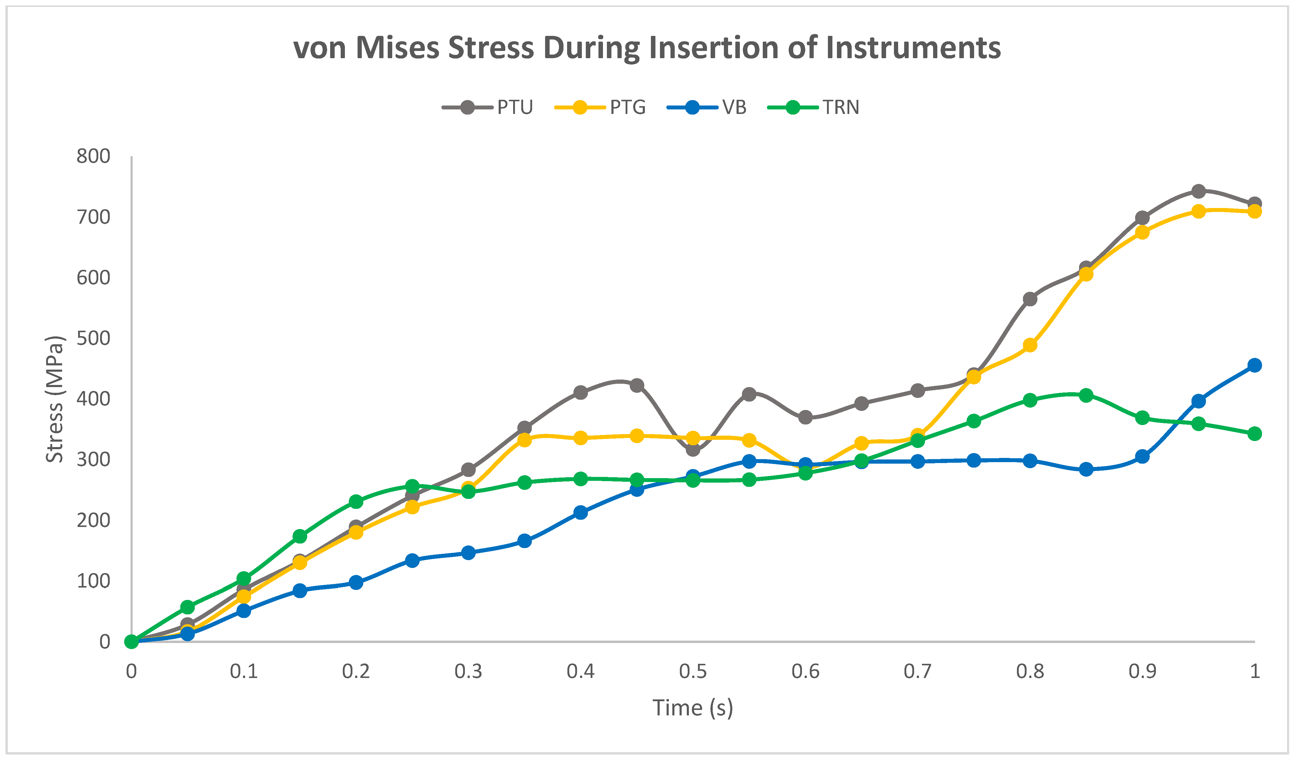
| Stock | ProTaper UniversalTM F2, 25 mm (PTU) | 25/06v | 250 | 2.0 |
| Gold | ProTaper GoldTM F2, 25 mm (PTG) | 25/06v | 300 | 3.1 |
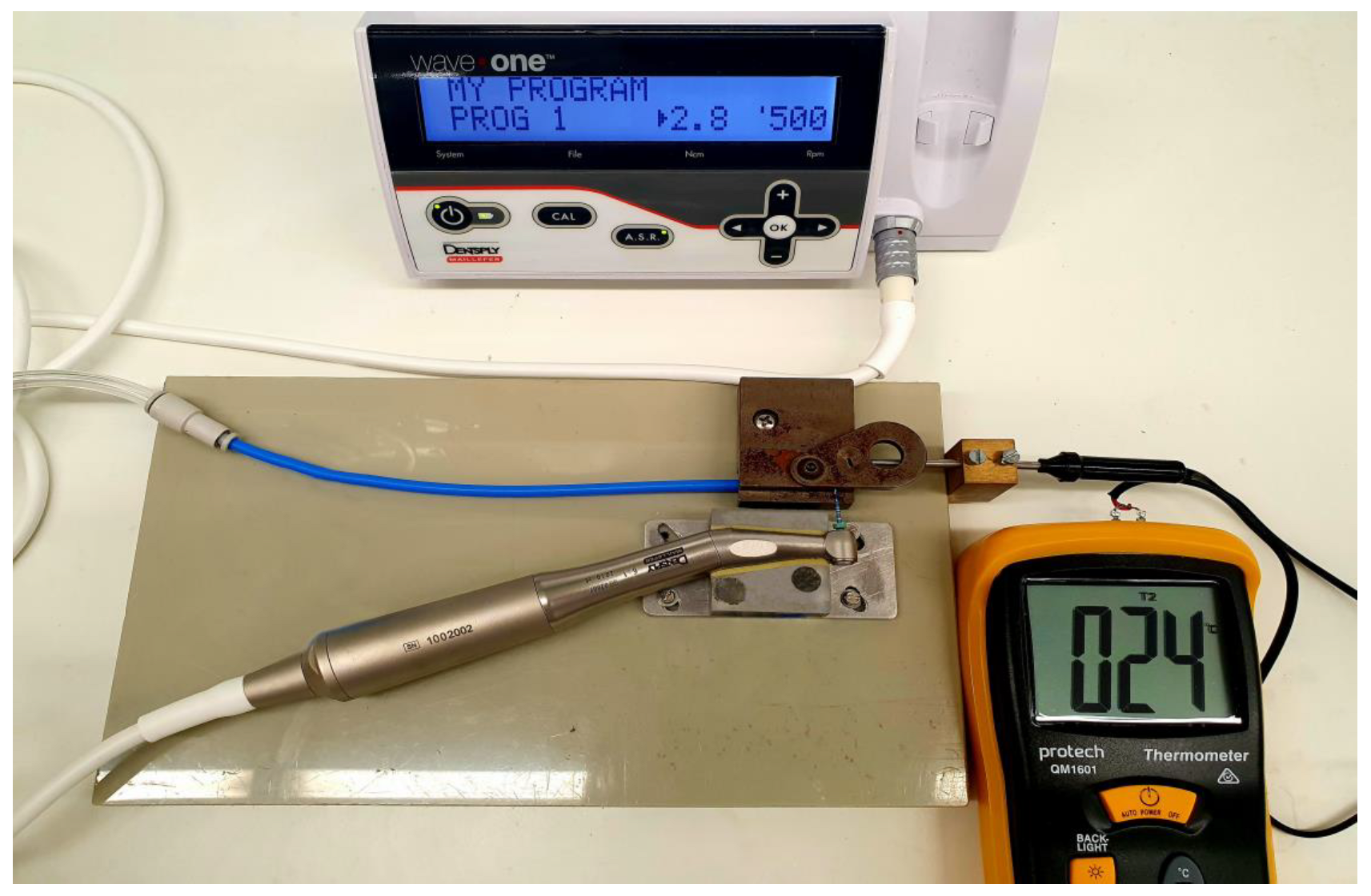
| Blue | Vortex BlueTM, 25 mm (VB) | 25/06v | 500 | 2.8 |
| Superflex | TruNatomyTM Prime, 25 mm (TRN) | 26/04v | 500 | 1.5 |
| Symbol | Parameter | PTU | PTG | VB | TRN |
|---|---|---|---|---|---|
| Austenite elasticity (MPa) | 28,248 | 30,573 | 28,672 | 26,580 | |
| Austenite Poisson’s ration | 0.33 | 0.33 | 0.33 | 0.33 | |
| Martensite elasticity (MPa) | 20,146 | 21,254 | 20,900 | 21,029 | |
| Martensite Poisson’s ration | 0.33 | 0.33 | 0.33 | 0.33 | |
| Transformation strain | 0.0445 | 0.0377 | 0.0385 | 0.0356 | |
| Loading | 6.7 | 6.7 | 6.7 | 6.7 | |
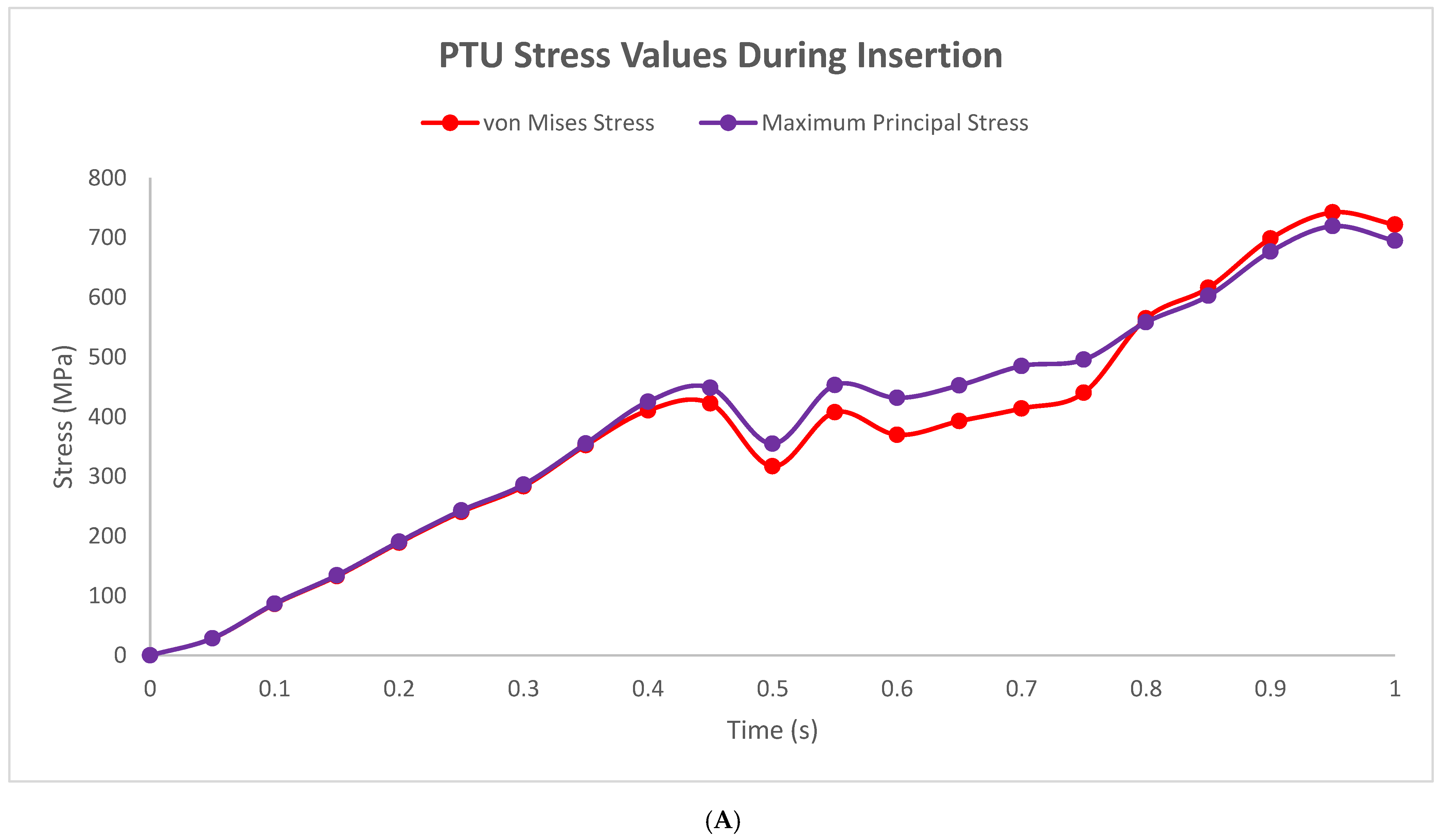
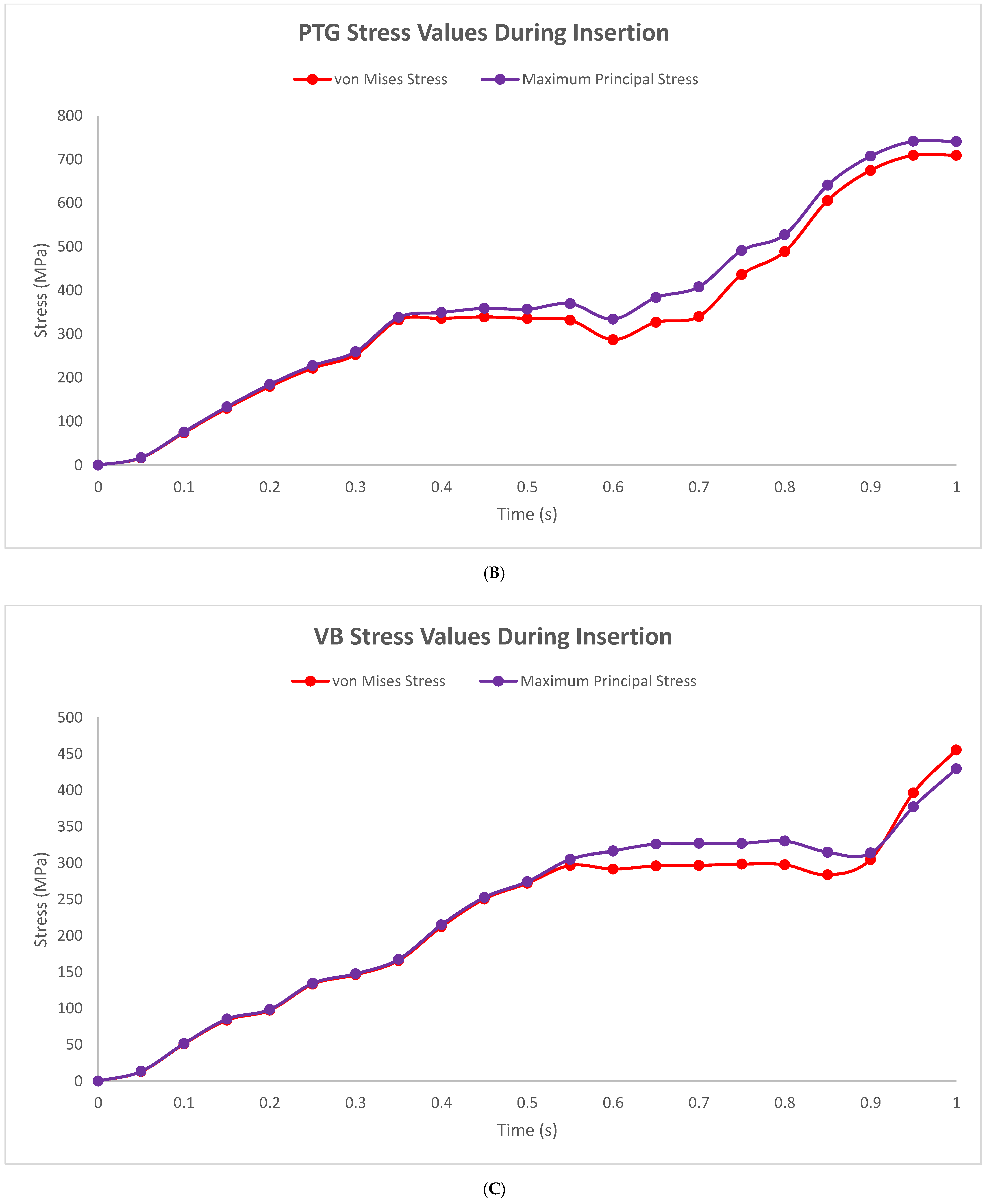
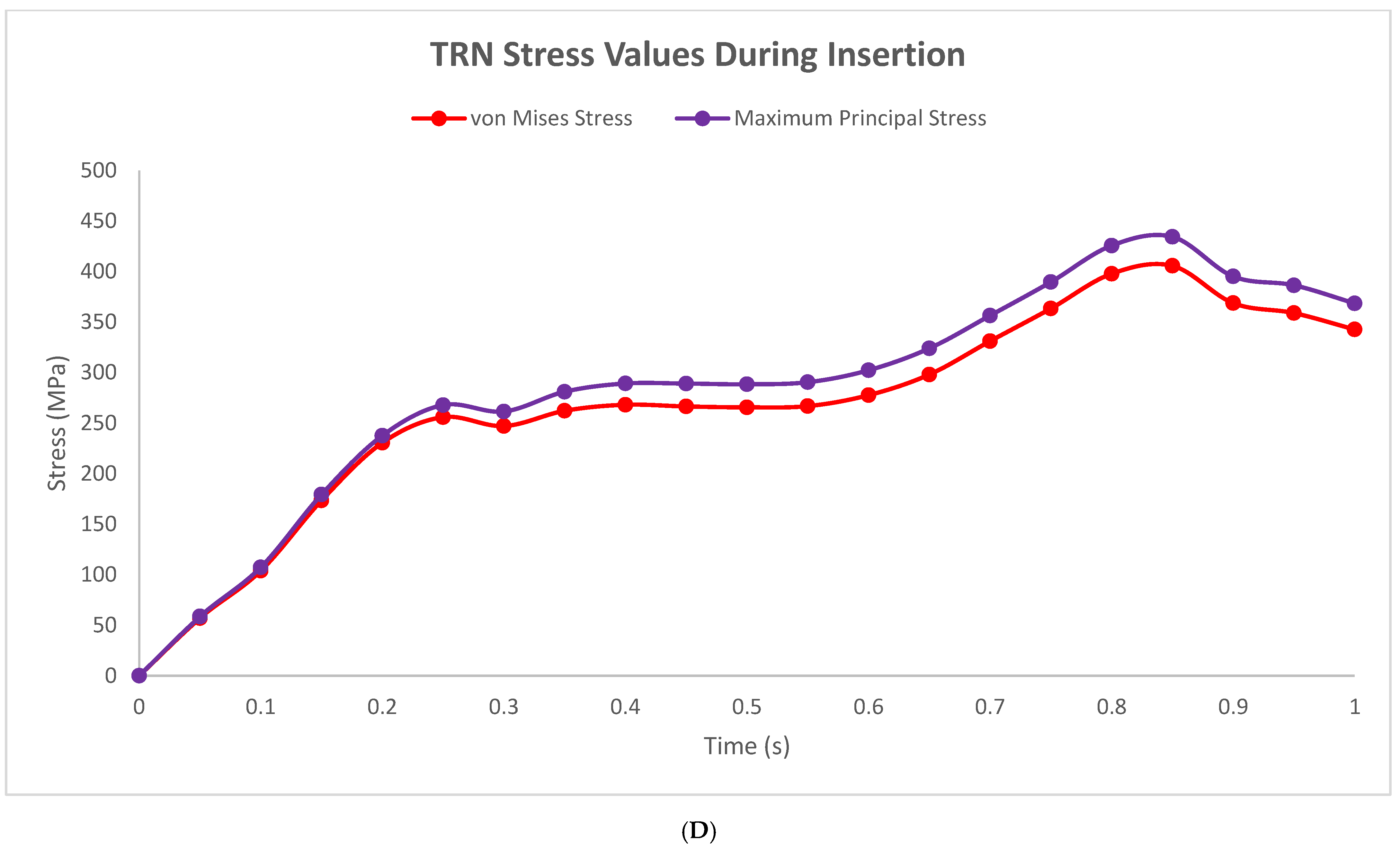
| Start of transformation loading (MPa) | 422 | 341 | 296 | 266 | |
| End of transformation loading (MPa) | 481 | 424 | 351 | 366 | |
| Reference temperature (°C) | 25 | 25 | 25 | 25 | |
| Unloading | 6.7 | 6.7 | 6.7 | 6.7 | |
| Start of transformation unloading (MPa) | 161 | 161 | 161 | 161 | |
| End of transformation unloading (MPa) | 118 | 118 | 118 | 118 | |
| Start of transformation stress in compression (MPa) | 28,248 | 30,573 | 28,672 | 26,580 |
| Instrument | NCF (Dimensionless) | Strain (%) | Fragment (mm) |
|---|---|---|---|
| ProTaper Universal (PTU) | 600.90 ± 80.86 | 6.29 ± 0.47 | 5.36 ± 0.79 |
| ProTaper Gold (PTG) | 1944.64 ± 189.86 | 5.98 ± 1.11 | 4.92 ± 1.80 |
| Vortex Blue (VB) | 1882.18 ± 353.35 | 4.66 ± 0.28 | 3.59 ± 0.47 |
| TruNatomy (TRN) | 2027.94 ± 452.50 | 4.49 ± 0.23 | 3.26 ± 0.47 |
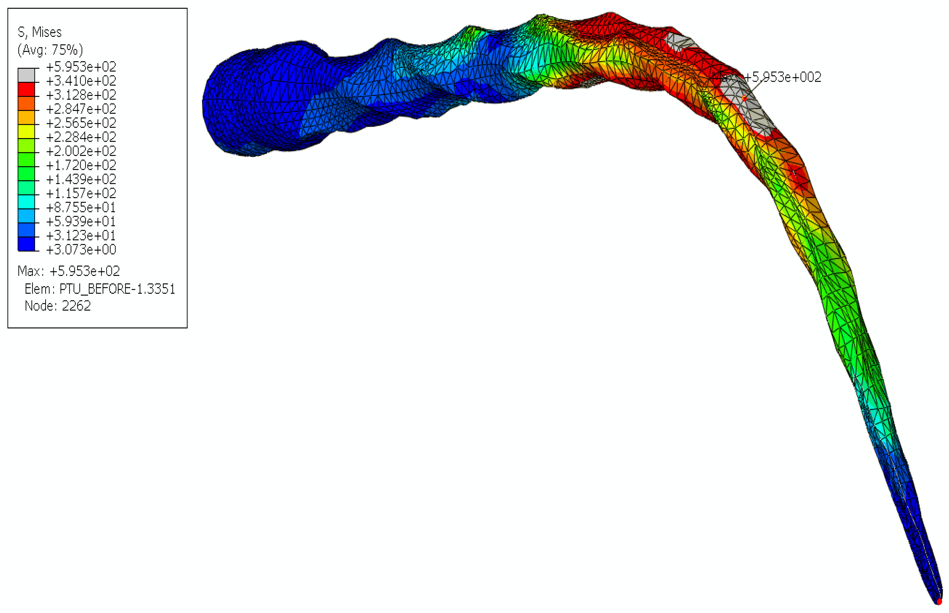
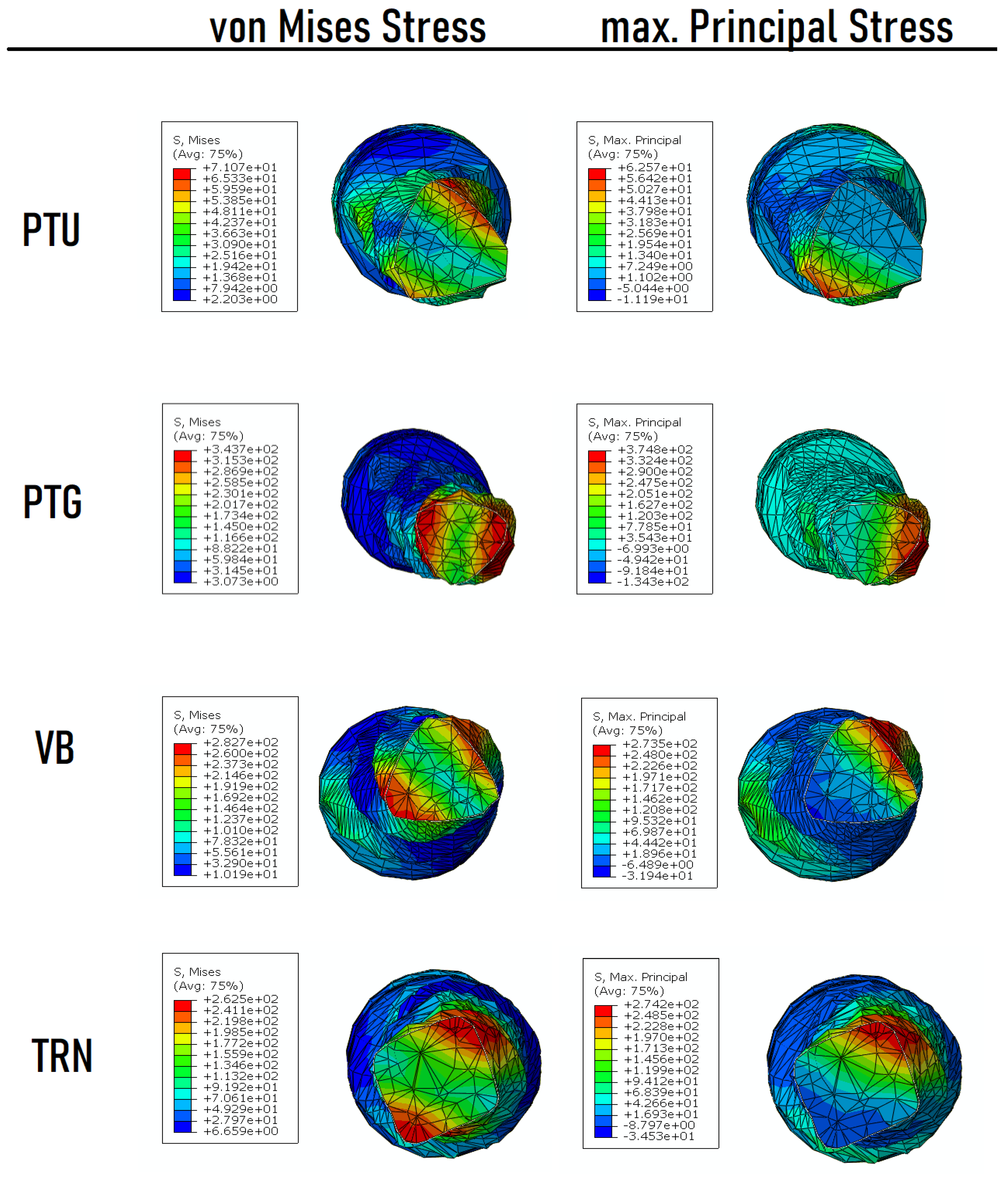
| Instrument | Experimental Fragment Length (mm) | Location of Peak von Mises Stress (mm) | Location of Maximum Principal Stress (mm) |
|---|---|---|---|
| ProTaper Universal (PTU) | 5.36 ± 0.79 | 5.16 | 5.12 |
| ProTaper Gold (PTG) | 4.92 ± 1.80 | 5.16 | 4.80 |
| Vortex Blue (VB) | 3.59 ± 0.47 | 5.74 | 4.70 |
| TruNatomy (TRN) | 3.26 ± 0.47 | 3.60 | 4.38 |
Disclaimer/Publisher’s Note: The statements, opinions and data contained in all publications are solely those of the individual author(s) and contributor(s) and not of MDPI and/or the editor(s). MDPI and/or the editor(s) disclaim responsibility for any injury to people or property resulting from any ideas, methods, instructions or products referred to in the content. |
© 2023 by the authors. Licensee MDPI, Basel, Switzerland. This article is an open access article distributed under the terms and conditions of the Creative Commons Attribution (CC BY) license (https://creativecommons.org/licenses/by/4.0/).
Share and Cite
Chien, P.Y.-H.; Wan, B.; Walsh, L.J.; Peters, O.A. Experimental and 2-Step Finite Element Analysis of Cyclic Fatigue Resistance of Conventional and Heat-Treated Rotary Endodontic Nickel-Titanium Instruments. Appl. Sci. 2023, 13, 2080. https://doi.org/10.3390/app13042080
Chien PY-H, Wan B, Walsh LJ, Peters OA. Experimental and 2-Step Finite Element Analysis of Cyclic Fatigue Resistance of Conventional and Heat-Treated Rotary Endodontic Nickel-Titanium Instruments. Applied Sciences. 2023; 13(4):2080. https://doi.org/10.3390/app13042080
Chicago/Turabian StyleChien, Philip Yuan-Ho, Boyang Wan, Laurence James Walsh, and Ove Andreas Peters. 2023. "Experimental and 2-Step Finite Element Analysis of Cyclic Fatigue Resistance of Conventional and Heat-Treated Rotary Endodontic Nickel-Titanium Instruments" Applied Sciences 13, no. 4: 2080. https://doi.org/10.3390/app13042080