1. Introduction
Manufacturing is the main motivation for people comfort and success. However, it also forcefully chips in directly and indirectly to the want of natural resources, environment and social conflicts. Thus, detection of solutions to a more sustainable development of global manufacturing-which together brings up the triple bottom line with the three dimensions of sustainability-is of significance and more immediate than ever. The adoption of hybrid manufacturing techniques as a means for sustainable production is becoming increasingly appealing in today’s industrial landscape. These approaches are geared towards minimizing energy consumption, optimizing the manufacturing process, and ultimately reducing production costs across a spectrum of products. Among these techniques, hot machining, often referred to as thermally enhanced machining, has gained significant attention. Hot machining involves the process of working with challenging-to-machine metals and alloys at elevated temperatures, facilitated by an external heat source. This controlled heating serves to soften the material, ultimately enhancing its machinability. The benefits of hot machining include reducing machining power requirements, improving the quality of the machined surface, and prolonging tool life. AISI630 steel is a type of stainless-steel alloy with a martensitic matrix which is mainly used in the military, petrochemical, nuclear and aerospace industries [
1]. AISI630 stainless steel is also used in the manufacture of pressure vessels and components exposed to high-stress and corrosive environments in oil and gas industries. The main hardening mechanism of this steel is age hardening or precipitation hardening. The age hardening temperature of this steel is from 482 °C to 621 °C (900 °F to 1150 °F) and the maximum hardness could be around 48 HRC, which is obtained by age hardening for one hour at 482 °C. In the context of machining AISI630 hardened stainless steel, its high hardness, coupled with the presence of dispersed fine-grain copper deposits and hard carbide particles like niobium carbide within the martensitic matrix, leads to significant cutting tool wear and subpar workpiece surface quality. Researchers and industries have turned to hot machining processes to tackle the challenges posed by hard-to-cut materials [
2]. For instance, Chang and Koo [
3] delved into laser-assisted turning of Al
2O
3 ceramic, where their findings indicated that hot turning can substantially reduce workpiece surface roughness and cutting force by approximately 70% and 20%, respectively [
4]. Similarly, super-alloys, known for their high cutting forces and tool wear, have been investigated through laser-assisted turning of Inconel 718 super-alloy, revealing a remarkable 35% reduction in specific energy, a 22% improvement in surface roughness, and reduced tool wear when compared to conventional cutting [
5]. In the case of challenging materials like Metal Matrix Composites, renowned for their high strength and hardness but notorious for causing extensive tool wear and subpar surface quality, Wang et al. explored laser-assisted machining of an aluminum metal base composite enriched with fine Al
2O
3 particles [
6]. Their research unveiled the potential to lower cutting force, enhance surface roughness, and extend tool life by increasing the preheating temperature. However, it’s worth noting that while hot machining is generally effective in reducing surface roughness, cutting force, and tool wear for many hard-to-cut materials, it may inadvertently elevate tool temperature, a situation observed in certain metals like titanium alloys, consequently leading to increased cutting tool wear. Results from a study on Ti-6Al-4V alloys highlight the decrease in cutting force with increasing workpiece preheating temperature during hot machining, albeit with only a marginal improvement in cutting tool life when the preheating temperature is raised to 250 °C [
7]. Conversely, pushing the workpiece preheating temperature to 350 °C results in a reduction in cutting tool life compared to conventional turning. Given the extensive use of AISI630 hardened stainless steel in industries like the military, power plants, and petrochemical sectors, researchers have dedicated attention to studying tool wear and machinability for this particular steel [
8]. For instance, Mohanty et al. explored the effects of various turning parameters on tool wear and surface roughness in AISI630 steel with a hardness rating of 35 HRC, offering recommendations for cutting speed ranges for carbide cutting tools [
9]. Sivaya and Chakradar delved into the study of cutting tool flank wear and machined surface roughness in AISI630 steel during conventional turning [
10]. They also employed cryogenic cooling techniques using liquid nitrogen and minimal quantity lubrication to mitigate tool wear. Khani et al. focused on assessing the impact of preheating temperatures on cutting tool wear during hot turning of AISI630 steel with a hardness rating of 43 HRC, incorporating plasma and simultaneous cooling of the cutting tool [
11]. Their results indicated that a combination of hot turning and cryogenic cooling, known as hybrid machining, could effectively reduce cutting tool wear and surface roughness. Lastly, laser hot milling experiments were conducted on AISI630 stainless steel specimens in a study. The findings demonstrated that preheating the workpiece to 300 °C in hot milling resulted in a 33% reduction in cutting forces and a consequent 50% reduction in tool wear when compared to conventional milling operations. In the present investigation, both conventional dry turning and hot turning techniques were employed to machine AISI630 hardened stainless steel specimens, focusing on exploring the mechanisms behind cutting tool flank wear and crater wear [
12,
13,
14,
15,
16,
17,
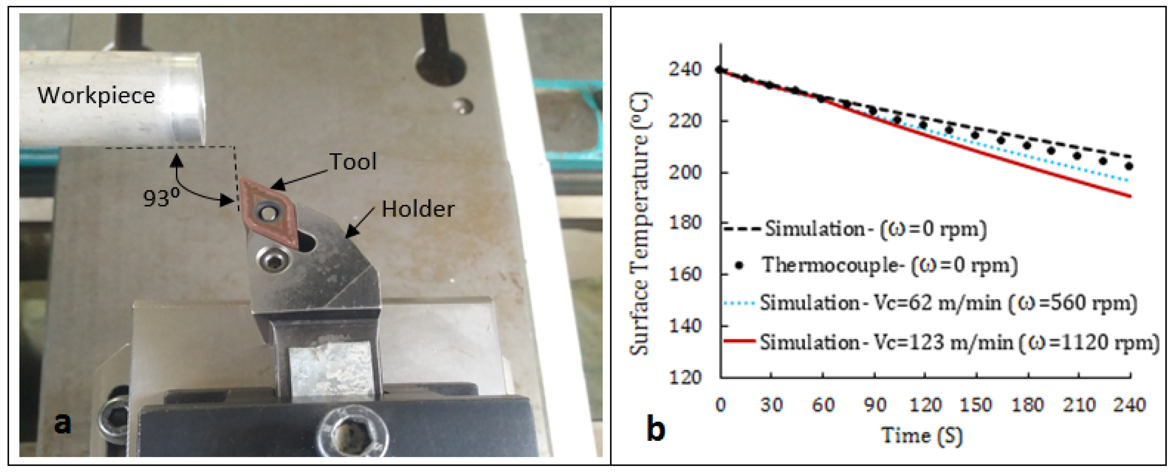
18]. Workpiece surface morphology and roughness have also been studied under different conditions and at different workpiece preheating temperatures. Tool tip temperature has been estimated and calculated by applying a validated finite element model to analyze and interpret the reasons for cutting tool wear in preheating machining contrasted to traditional machining operation.
3. Results and Discussion
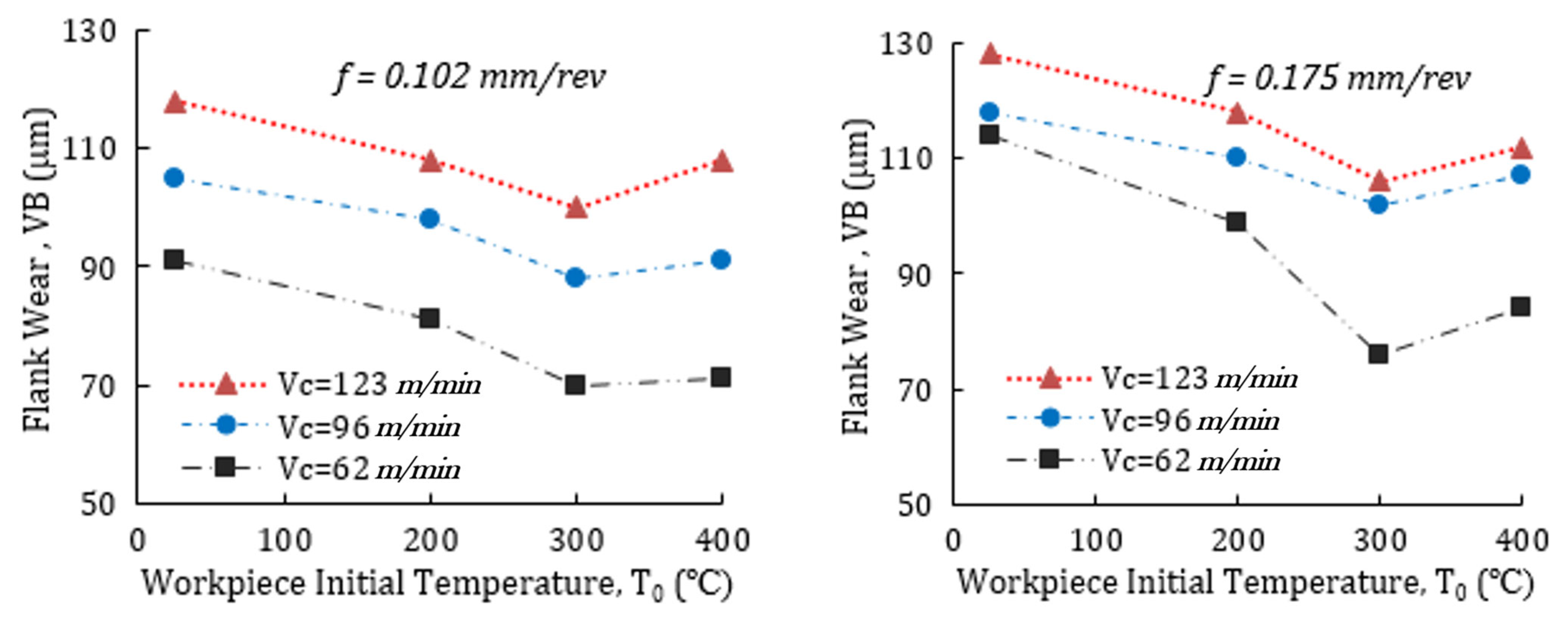
Figure 2 shows cutting tool flank wear values at different workpiece preheating temperature and feed values. It can be seen that by preheating the workpiece at 200 °C, tool flank wear is reduced compared to conventional turning (at ambient temperature) at all cutting speeds. Although, increasing preheating temperature to 300 °C decreases tool flank wear continuously, by rising the primary temperature of workpiece to 400 °C, the flank wear values not only do not decrease but also increase compared to turning at 300 °C at cutting speeds of 96 m/min and 123 m/min. As it is indicated in
Figure 2, these phenomena have been observed for both cutting tool feeds of 0.102 mm/rev and 0.175 mm/rev.
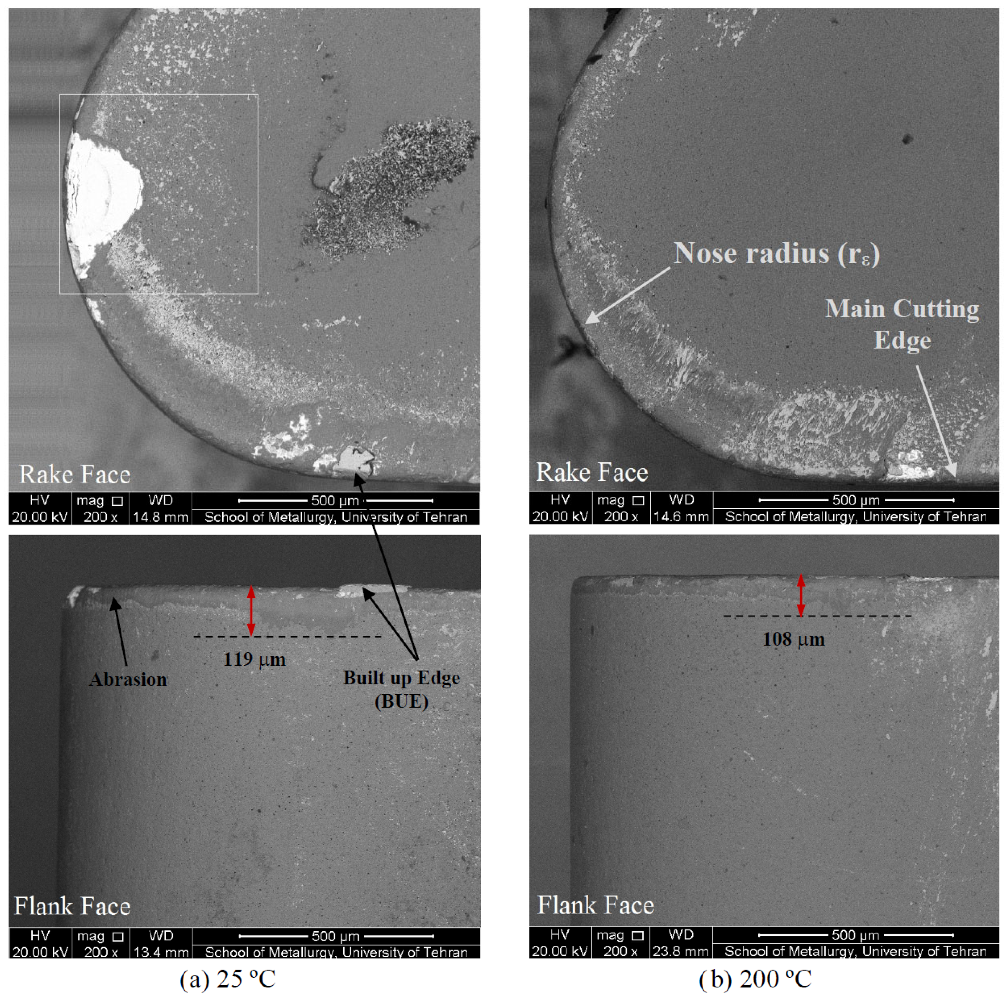
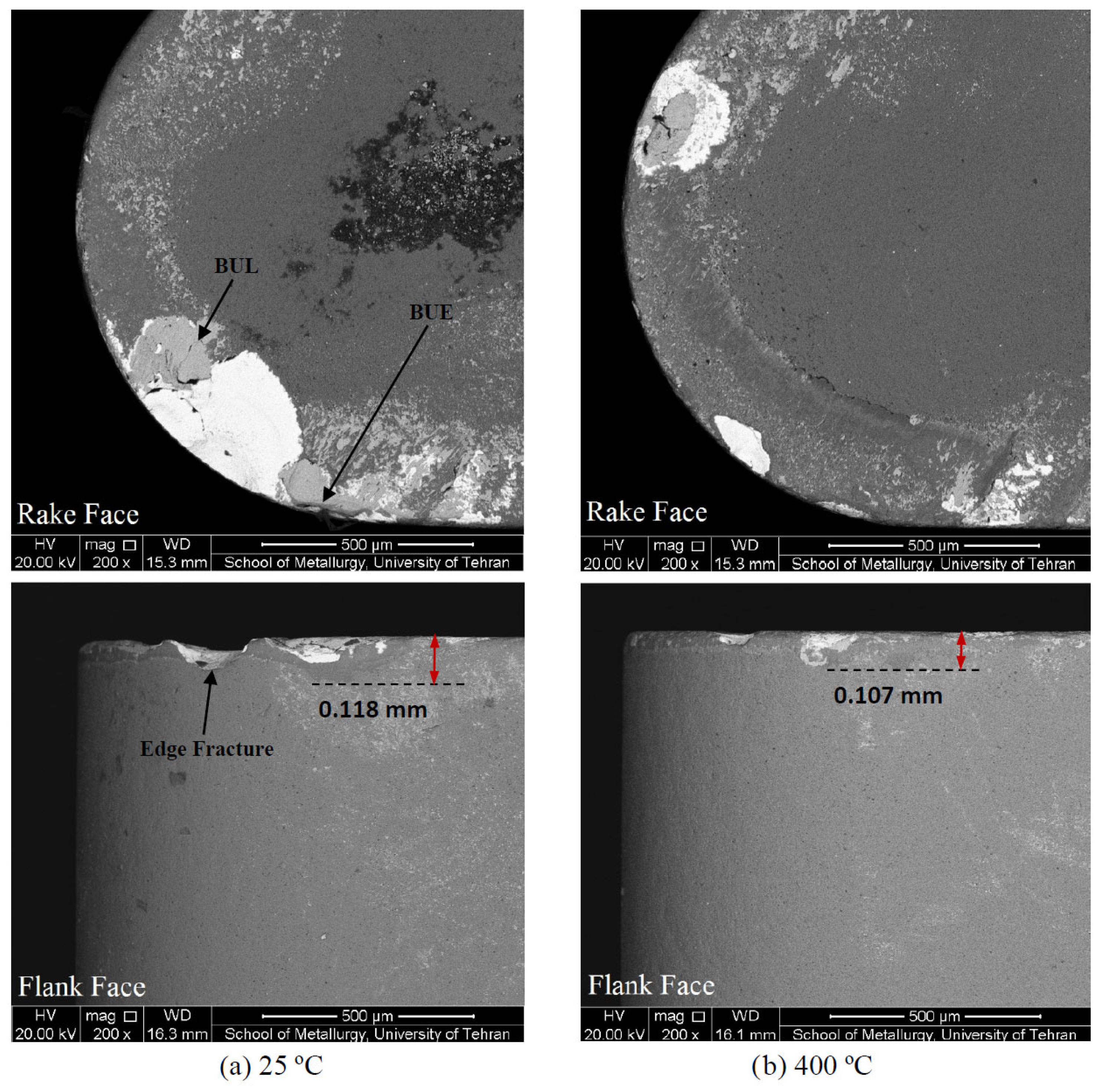
Figure 3 presents scanning electron microscope (SEM) images that illustrate the differences in cutting tool flank wear and crater wear under various workpiece preheating temperatures and turning conditions. The comparison is striking, as it demonstrates a significant reduction in the severity of wear on the cutting tool’s rake face when employing the preheating turning technique at 400 °C in contrast to traditional turning operation at room temperature.
Figure 3a reveals that the tool flank wear width measures 119 μm in conventional turning. However, in the case of hot turning at 200 °C and 300 °C, the tool flank wear width is reduced to approximately 108 μm and 100 μm, respectively (as shown in
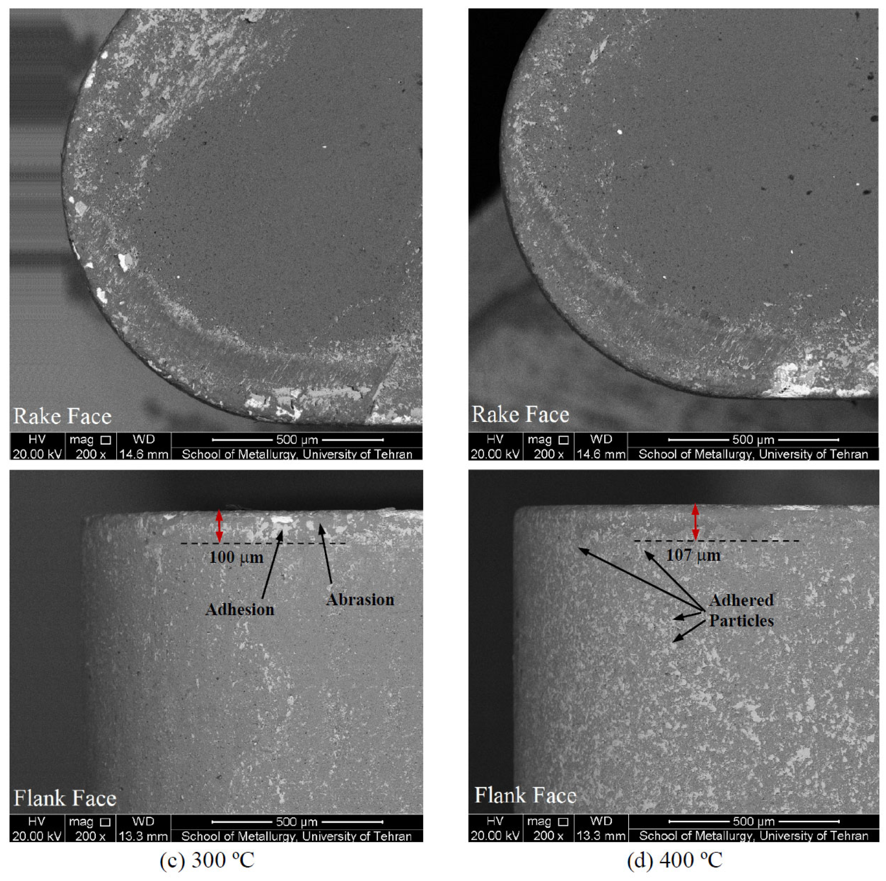
Figure 3b,c). Additionally, at a preheated temperature of 400 °C, the cutting tool flank wear width measures 107 μm. This transition from a workpiece preheating temperature of 200 °C to 400 °C results in an increased number of fine particles from the workpiece material adhering to the tool flank face (as indicated in
Figure 3). Consequently, in this scenario, the optimal workpiece preheating temperature to minimize tool flank wear is considered to be 300 °C.
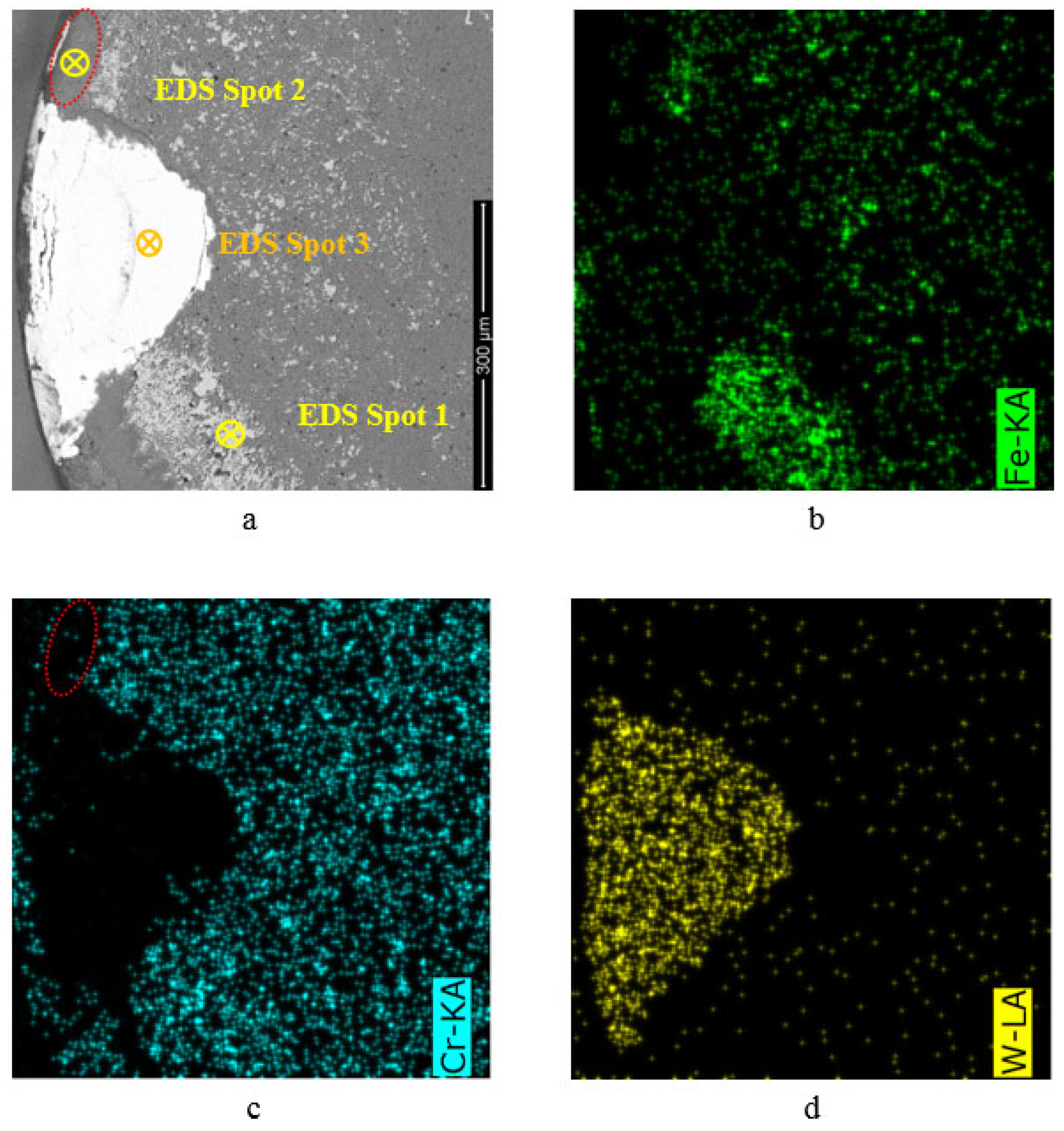
Figure 4a shows a magnified illustration of the white box distinguished in
Figure 3a. In this figure, different areas on the worn tool have been identified using Energy Dispersive X-ray (EDS) maps. Therefore, to completely and precisely investigate the wear mechanism, different areas on the rake face and flank face of all cutting tools used, in this study, under different turning conditions have been identified by applying EDS maps.
Figure 4 indicates that the tool wear mechanism in conventional turning is abrasive and adhesive types. On the rake face of the cutting tool, the area in which the workpiece material (chip) adheres on the tool surface has been marked with the phrase “Fe”. This area is completely covered by iron (Fe-rich) and is therefore easily recognizable in EDS maps (
Figure 4b).
Table 1 shows the chemical composition of this figure which is the result of the analysis of point EDS spot 1. This chemical composition is exactly similar to that of workpiece material, so it can be concluded that this material is adhered/welded on the tool surface as Built-up Layer (BUL) [
18]. To put it differently, there are instances where adhesion has been combined with abrasion, resulting in the specimen’s material strongly adhering or welding to the tool’s top coating (AlCr
2O
3). As the cutting process continues, this material is gradually removed from the tool’s surface. Consequently, this process reveals the cutting tool’s base coating layer (TiAlN), leading to areas where the top layer (Al,Cr)
2O
3 has been removed, and chromium is no longer present. In these chromium-free areas, the first layer of coating has been stripped away (as shown in
Figure 4c), and you can observe the (Ti,Al)N coating on the tool. For instance, the region marked within the oval in both
Figure 4a,c is devoid of chromium. A chemical analysis conducted at EDS spot 2 confirmed that the chemical composition of this area corresponds to (Ti,Al)N, as indicated in
Table 1. In some sections of the tool’s flank face, the abrasion wear has been so severe that the workpiece material adhered to the tool surface, resulting in the removal of the upper and middle layers of the tool coatings. This revealed the tool’s bulk material, which is tungsten carbide (bare WC), as depicted in
Figure 4d. The chemical composition of point EDS Spot 3 in this region in
Figure 4a (
Table 1) confirms the existence of the element tungsten in this area. It is clearly illustrated in
Figure 3a–d that with increasing workpiece preheating temperature in hot machining, the cutting tool resulting in abrasion and adhesion mechanisms have been reduced [
18].
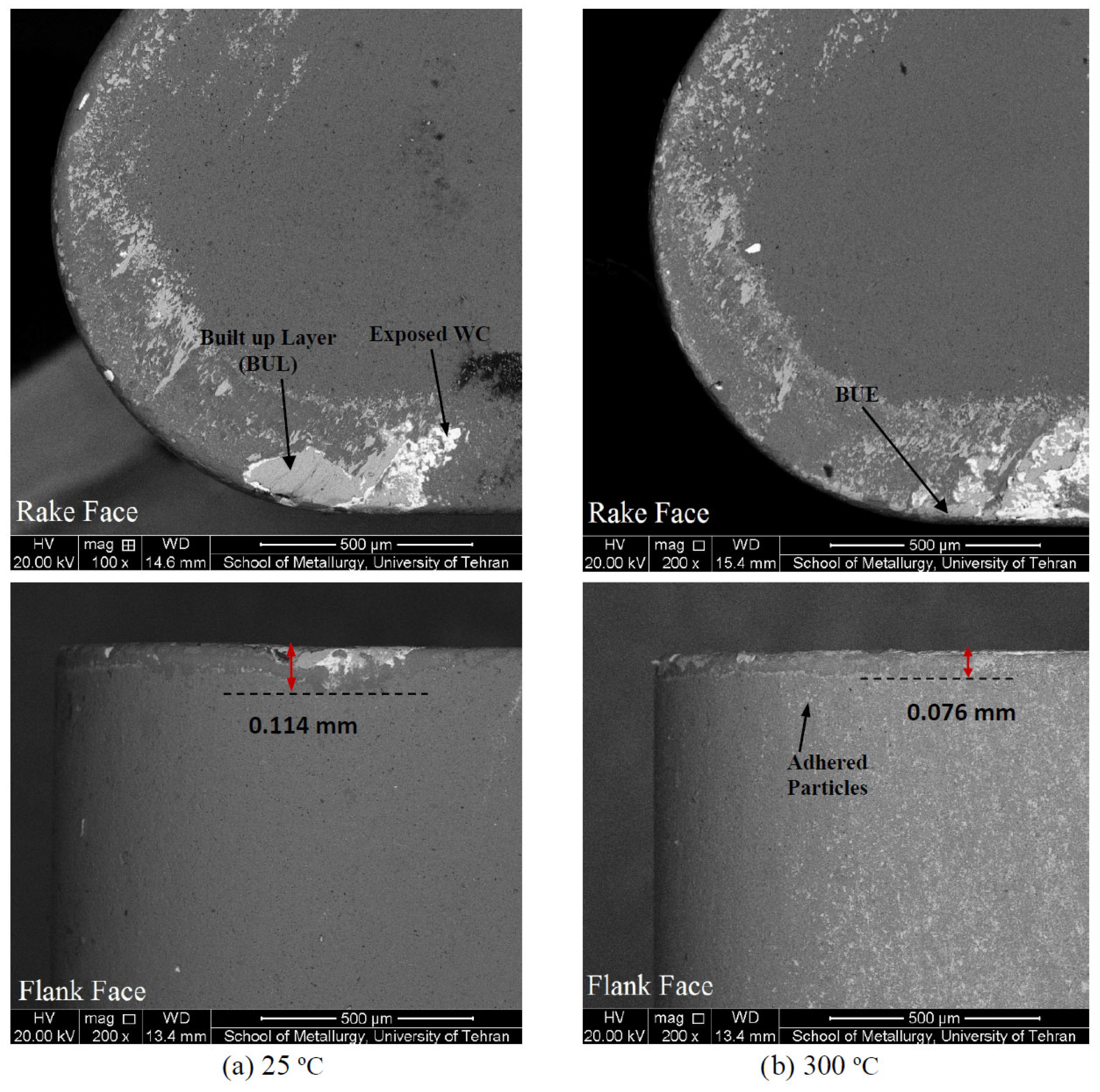
SEM micrographs of cutting tool flank wear and crater wear are shown in
Figure 5. It is indicated from
Figure 5 that the flank wear width during conventional turning is 114 µm (
Figure 5a) while applying hot turning reduces the flank wear width to 76 μm (
Figure 5b). however, increasing the workpiece preheating temperature to 400 °C results in increasing flank wear to 84 μm (
Figure 5c). Therefore, improved machining performance concerning the cutting tool wear can be obtained under a hot turning process with a workpiece preheated temperature of 300 °C.
Figure 5d shows a magnified illustration of the black box marked on the tool flank face. As a result, it has been found by the chemical analysis of point Spot 4 that the chemical composition of this part is like that of the workpiece material adhered to the tool face as Built of Edge (BUE). Moreover, the chemical composition of point Spot 5 also includes the elements Ti, Al, and N; indicating that the upper coating of the cutting tool has been removed under abrasion while the tool’s middle coating still exists on the tool bulk material (sublayer; tungsten carbide-bare WC).
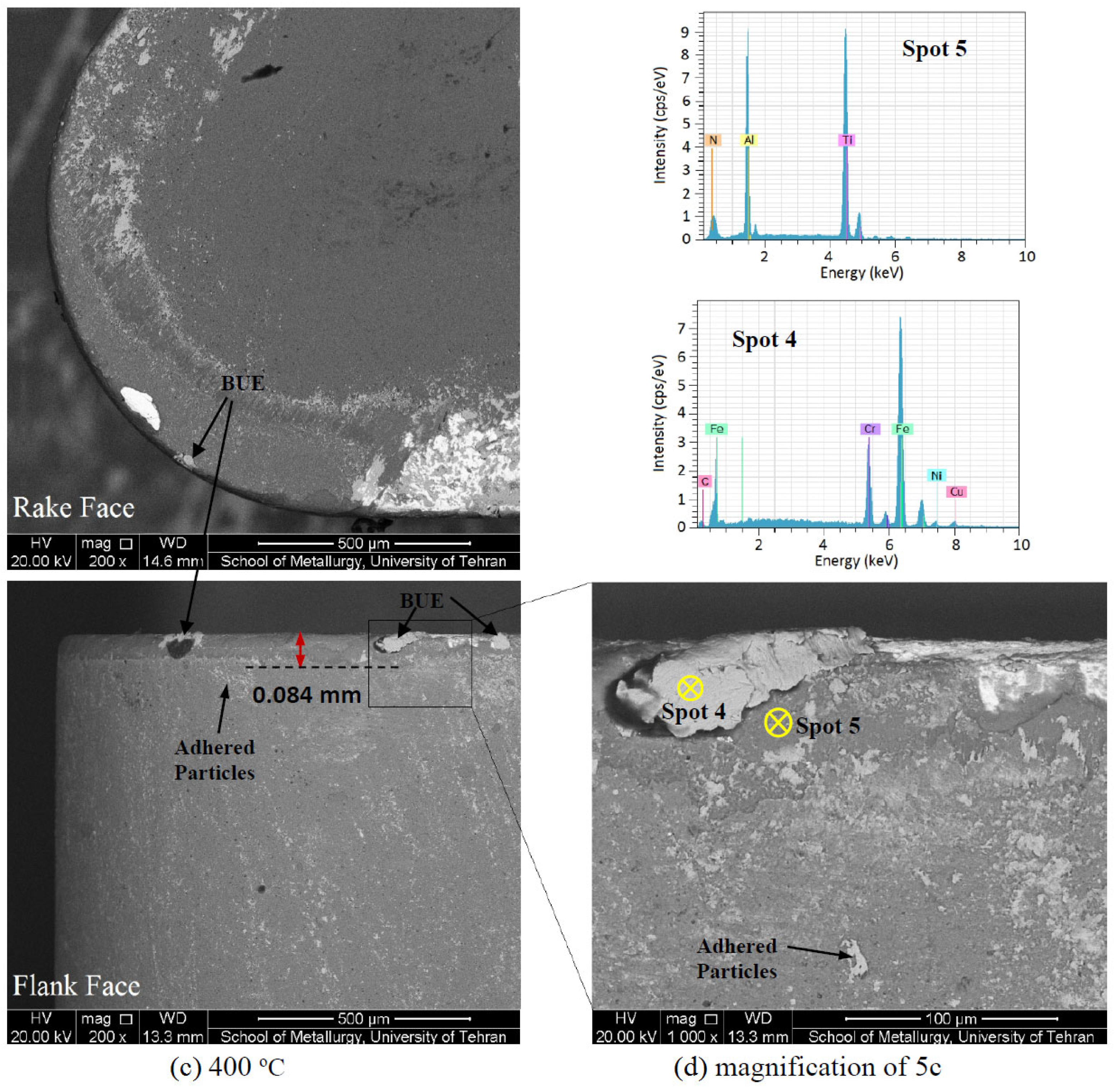
Cutting tool flank wear and crater wear for different machining processes are shown in
Figure 6. As it is indicated in this figure, during conventional turning, the tool cutting edge has been broken in the nose radius section (Edge Fracture) on the rake face, and consequently, the tungsten carbide is visible. However, this area where the carbide is trapped is visible and has been reduced significantly by performing hot turning at 400 °C. In addition, hot turning has been shown to reduce flank wear as well (
Figure 6).
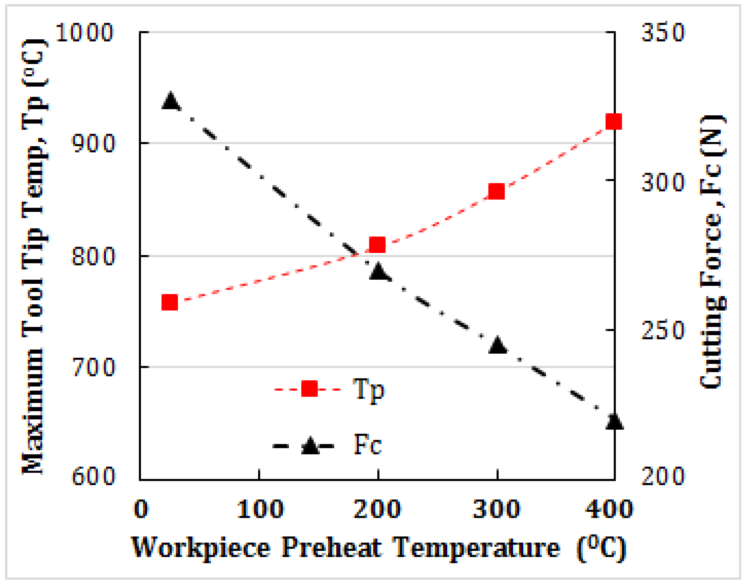
Cutting force and tool tip temperature values during turning processes have been calculated by applying a verified FEM analysis using Power Viscosity Law [
13]. The maximum tool tip temperature (T
p) and cutting force (F
C) for different workpiece preheating temperatures are plotted in
Figure 7. As
Figure 7 shows, with increasing the workpiece initial temperature from 25 °C to 400 °C, the maximum tool tip temperature increases from 760 °C to 920 °C, while the cutting force value has decreased from 327N to 220N (33% force reduction). Therefore, although hot turning increases the tool temperature, it significantly reduces the cutting force and applied stresses on the cutting tool edge. As a result, hot turning process reduces cutting tool wear. This fact has also been confirmed by the experimental results shown in
Figure 3.
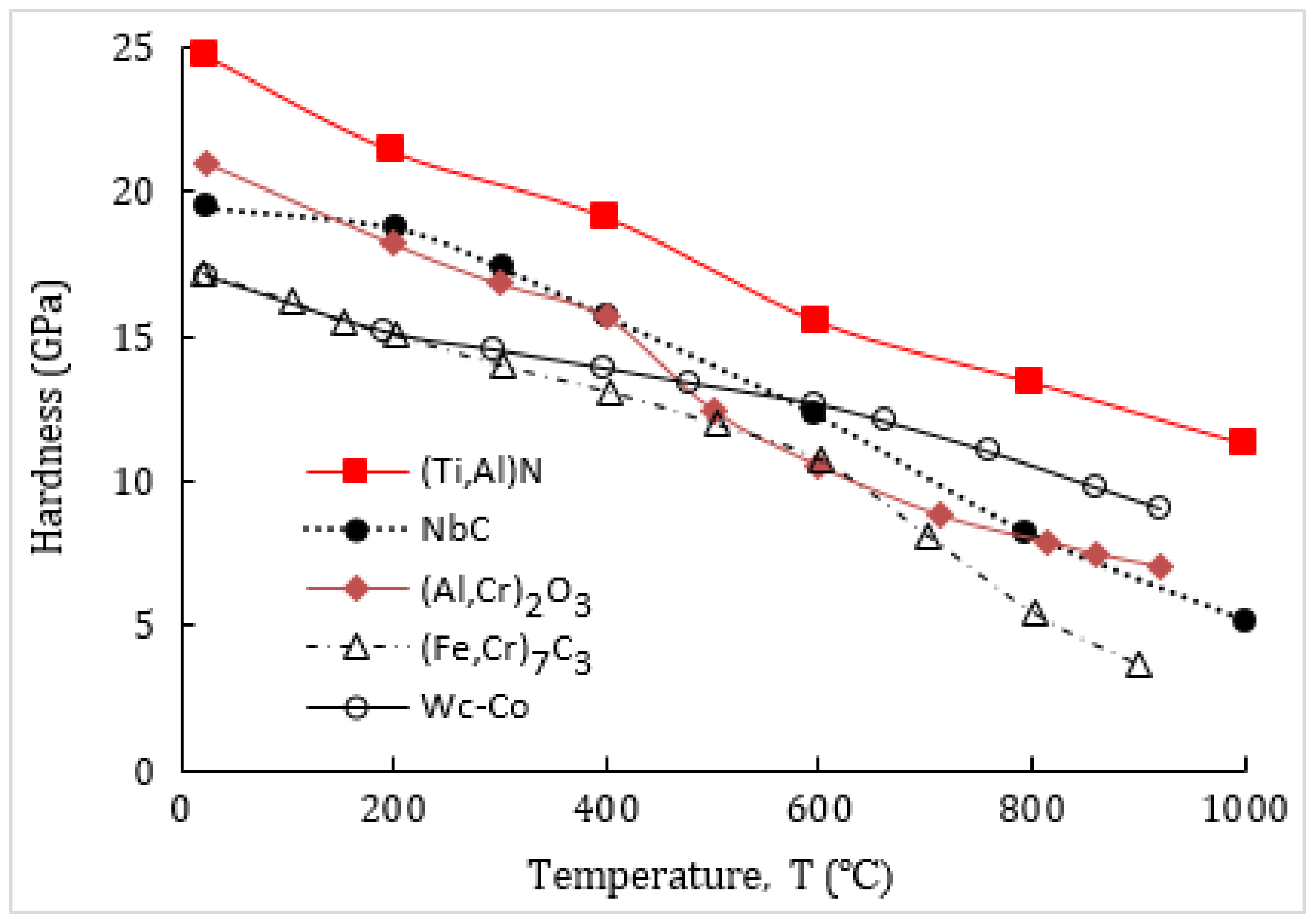
An Increase In the Initial temperature of the workpiece, and consequently, the elevation of the cutting zone temperature, results in a decrease in the hardness of the carbides present in the workpiece material. This decrease in hardness brings the carbides closer to the tool elements’ hot hardness, which is another factor contributing to the reduced wear of the tool observed in preheating machining in contrast to conventional machining. It’s worth noting that the martensitic matrix of the material used in the experiments (hardened AISI630 steel) holds Niobium Carbide and Iron-Chromium Carbide. These carbides exhibit varying hardness values, as depicted in
Figure 8a, with respect to temperature changes. Furthermore,
Figure 8b illustrates the changes in the hardness of the tool’s components with temperature variations. This includes the (Ti,Al)N coating, (Al,Cr)
2O
3, and the WC-Co substrate. The interplay between these hardness values is an important factor in understanding the differences in wear behavior between hot machining and conventional machining.
Since the mechanical properties and hardness values of both (Al,Cr)
2O
3 and Al
2O
3 coating layers are similar [
18],
Figure 8 incorporates the hardness data available presented in the previous studies for (Al,Cr)
2O
3, along with the hardness data for Al
2O
3. The literature review provided hardness values, as depicted in
Figure 8a,b. It’s important to highlight that, minor variations in hardness values could be due to differences in hardness measurement methods and various manufacturing parameters, like porosity, the size of the grains, and the chemical elements. For instance, as an illustration, two dissimilar hardness values have been presented for the two elements (Fe
0.64, Cr
0.36)
7C
3 and (Fe
0.415, Cr
0.585)
7C
3 [
16].
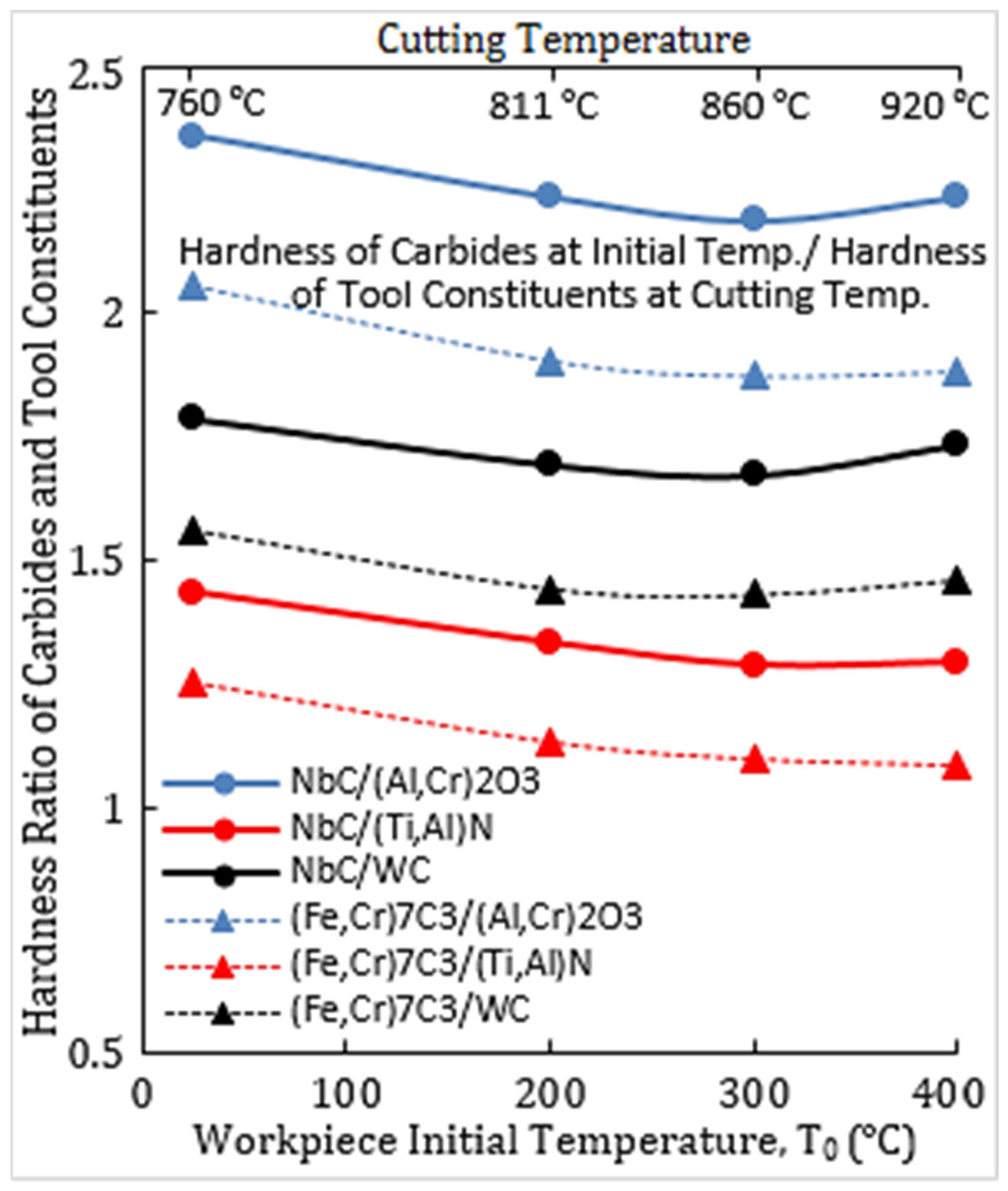
It is obvious that during turning operation the cutting tool reaches a stable temperature, which is called the tool/chip interface temperature or cutting temperature. As the martensitic phase of the workpiece material passes through the primary shear (deformation) zone, it undergoes severe plastic deformation and consequently its temperature increases. But the existing hard carbide phase in the bulk of the workpiece material undergoes a slight plastic deformation compared to the martensitic phase, so its temperature rise due to the plastic deformation is negligible. Further, because of the high thermal resistance of the available carbides in the workpiece background [
15] as well as their very short passage time through the secondary shear zone (tool/chip friction interface), their temperature in direct contact with the cutting tool face is much lower than the temperature of the cutting tool, and is approximately about the workpiece first temperature [
16].
Making the assumption that the carbide hardness ratio remains consistent, the calculations for the proportion of hardness of the carbide at the workpiece’s beginning temperature to the hardness of the tool constituents at the cutting temperature have been presented in
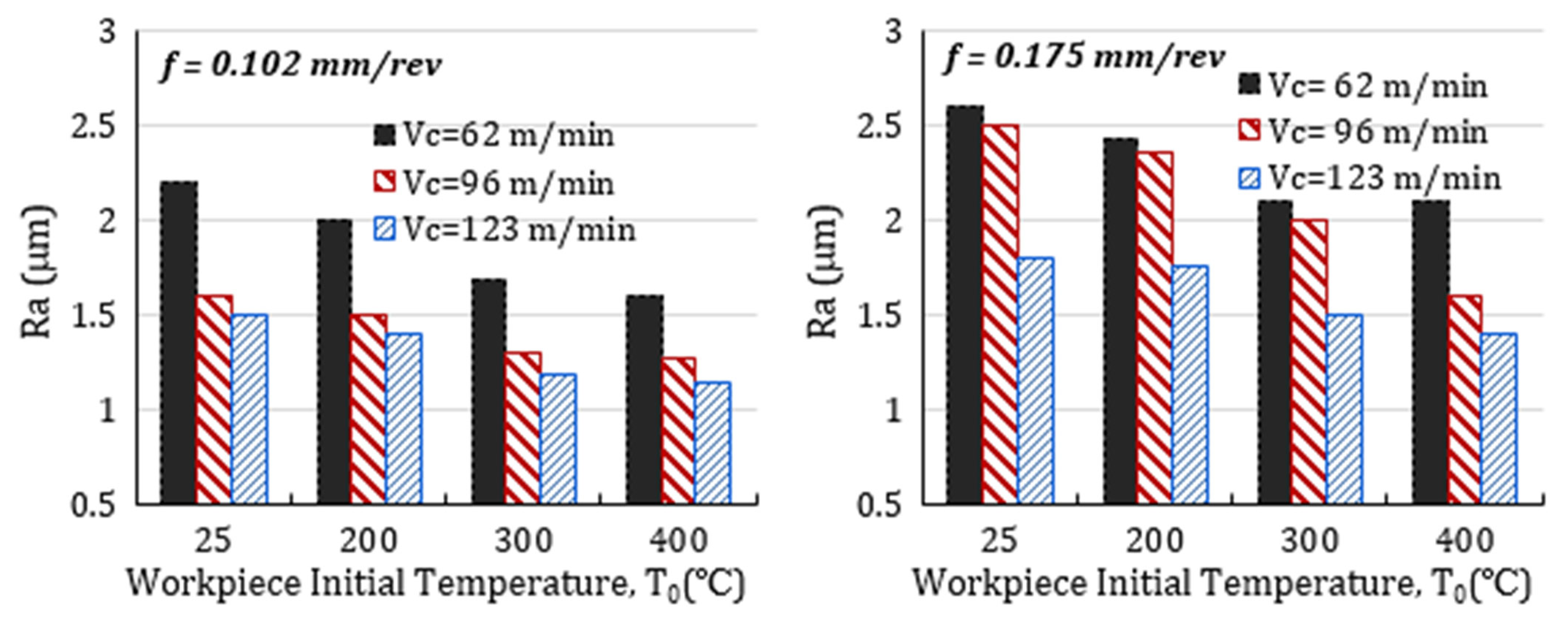
Figure 9. The results indicate that as the workpiece’s starting temperature increases from 25 °C to 300 °C, the ratio of carbide hardness to the hardness of the tool constituents decreases. This decrease, together with a notable decrease of cutting force during preheated turning (25%), contributes to a general decrease in abrasive wear in preheated turning in contrast to turning at room temperature. However, when the component’s beginning temperature is raised from 300 °C to 400 °C, there is a slight increase in the ratio of carbide hardness to the tool elements’ hardness. Consequently, the tool flank wear at 400 °C has slightly increased compared to that at 300 °C. The effects of initial temperature and cutting parameters on workpiece surface roughness are depicted in
Figure 10, illustrating a decrease in machined surface roughness during hot turning at 400 °C, with reductions of about 27% and 36% in contrast to traditional turning at feed rates of 0.102 and 0.175 mm/rev, respectively.
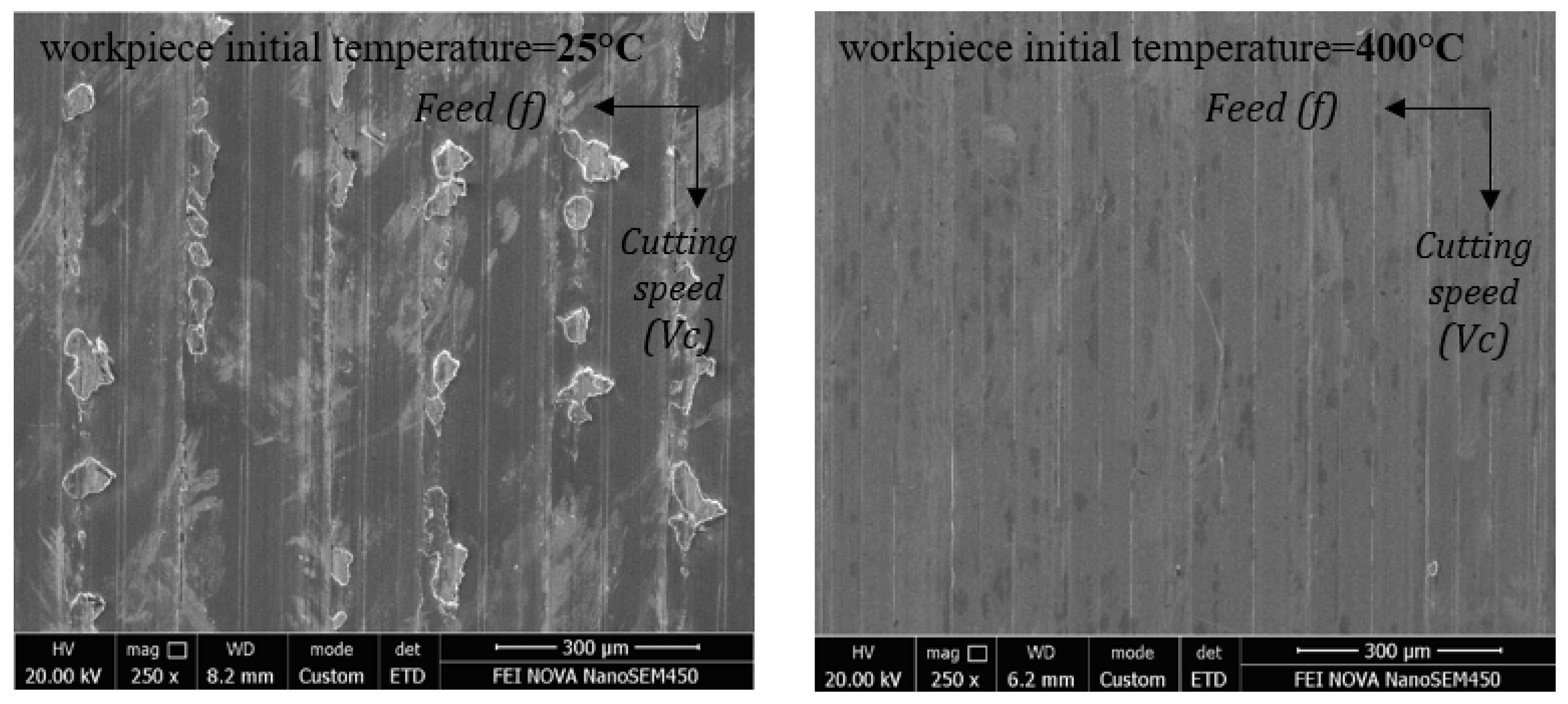
Figure 11 underscores the marked differences in the morphology of machined surfaces at different initial temperatures, indicating a significant influence of preheating techniques on chip-formation mechanisms.
The application of a thermally enhanced cutting technique results in machined surfaces with minimal side flows and defects. Conversely, surfaces produced under dry conditions at ambient temperatures exhibit side flow and more surface damage. Furthermore, an increase in cutting speed at each feed rate leads to a reduction in workpiece surface roughness (
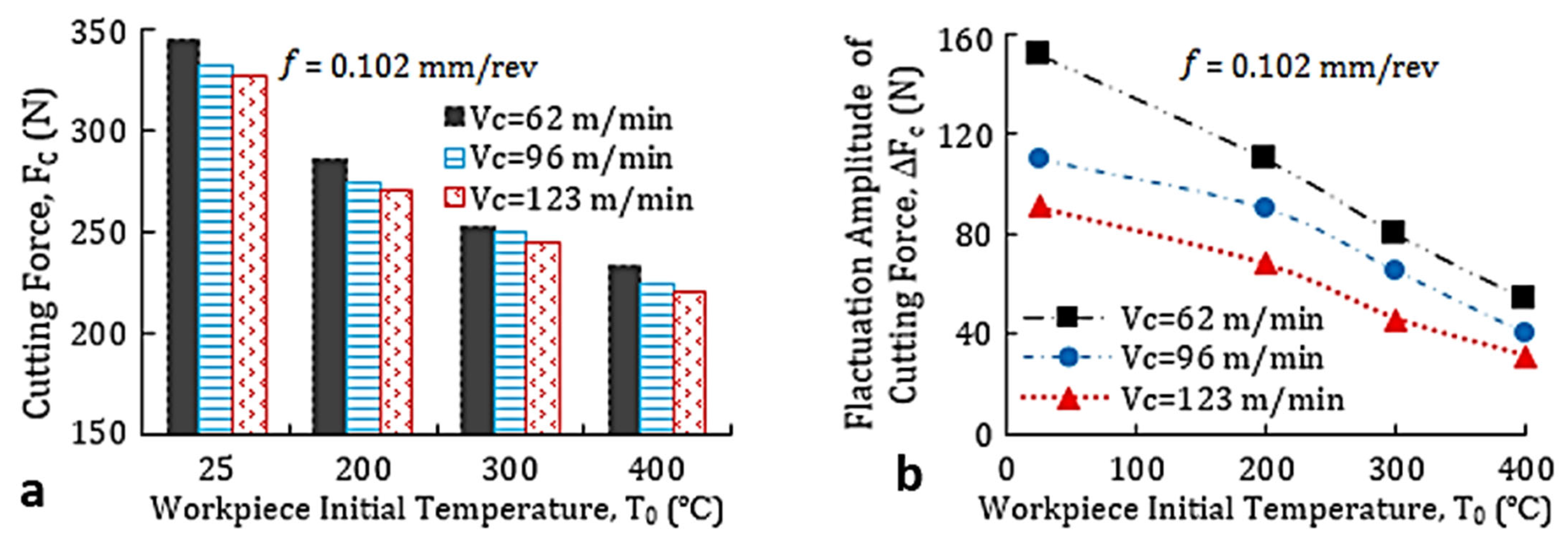
Figure 10). Additionally, elevating the workpiece’s initial temperature in hot turning reduces workpiece surface roughness compared to conventional turning. This increase in initial temperature results in reduced hardness and strength of the uncut chip, subsequently leading to decreased cutting forces (
Figure 12 and
Figure 13a). Consequently, workpiece surface roughness is diminished, enhancing the overall efficiency of the cutting process.
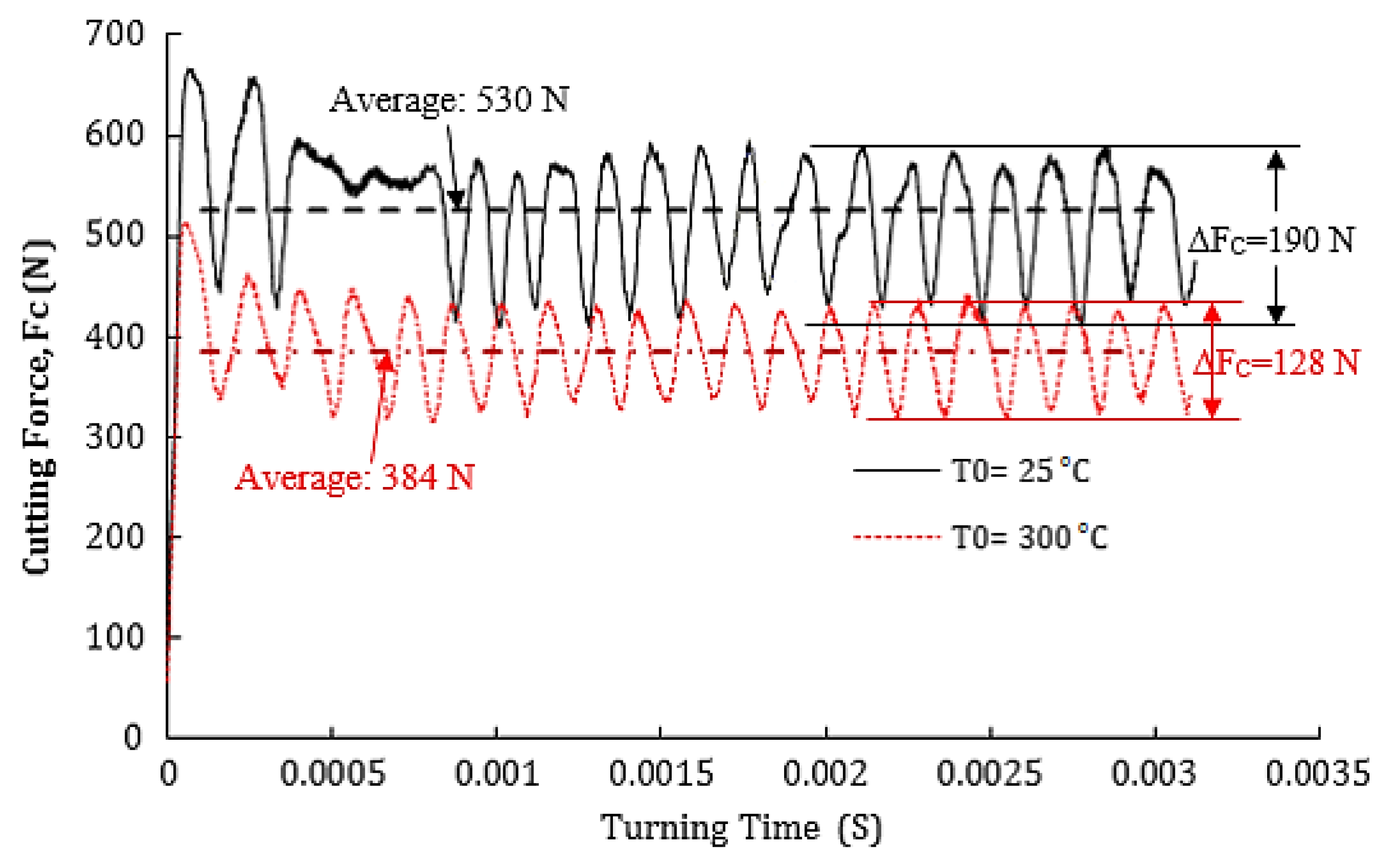
Figure 12 provides insight into the predicted cutting forces and their fluctuations at a cutting speed of 96 m/min and a feed rate of 0.175 mm/rev. The data in
Figure 12 demonstrates that the amplitude of the cutting force oscillation decreases with higher preheating temperatures.
Figure 13b illustrates the amplitude of the cutting force oscillation (peak to peak) for different cutting speeds.
Reducing cutting force oscillation (ΔF
C) in hot turning can be another cause of decreasing surface roughness in comparison to the achieved surface roughness in conventional turning operation. It has been observed in [
17] that the cutting tool will be under cyclic deflection when the saw-tooth chips are formed. The frequency of the cyclic deflection of cutting tool is close to the fluctuation frequency of the cutting force. In these conditions, as a result of tool cyclic deflection, cutting speed and tool’s rake angle are changed locally, and accordingly, the machined surface roughness of the workpiece increases. However, it has been found that preheating process applied in hot machining reduces the average cutting force (
Figure 13a), and at the same time it decreases the cutting forces’ fluctuation amplitude in comparison to conventional turning process (
Figure 13b). Therefore, hot turning operation enhances machining performance by improving surface finish and reducing cutting forces and cutting force fluctuation [
18].


