Article

CNN-Based Ti-6242 Impeller Forging Process Design for Uniform Strain Distribution

1
Department of Mechanical Engineering, Sogang University, Seoul 04107, Republic of Korea
2
Hanwha Aerospace Co., Ltd., Seongnam 13488, Republic of Korea
*
Author to whom correspondence should be addressed.
Appl. Sci. 2023, 13(14), 8272; https://doi.org/10.3390/app13148272
Submission received: 6 June 2023 / Revised: 6 July 2023 / Accepted: 14 July 2023 / Published: 17 July 2023
(This article belongs to the Special Issue Advanced Metal Forming and Smart Manufacturing Processes)

Abstract

:
In this study, we propose a systematic process design method using a convolutional neural network (CNN) for the uniform strain distribution of a Ti-6242 impeller during forging. A convolutional neural network (CNN) is a machine learning algorithm optimized for processing grid-like data, such as images, by identifying patterns within the data. To achieve the design goal with a simple process, we propose a methodological process in which the initial billet passes through three steps: upsetting, preform forging, and target impeller forging. We used the CNN model in the upsetting and preforming steps to enable our proposed design method to be applied to various impeller shapes. We trained a CNN model with two different types of datasets: one to derive the preform shape suitable for the target impeller forging and another to determine the shape of the initial billet that was upset for impeller preform forging. The proposed forging process resulted in a reduction in the mean strain, strain standard deviation, and maximum strain by up to 38.6%, 52.5%, and 59.7%, respectively, compared with the impeller forging processes proposed in previous studies. Consequently, the strain of the forged product was been homogenized, thereby reducing the possibility of defects. This process design method can be used in fields such as aerospace that require high-quality forging.

1. Introduction

Ti-6242 is known to have excellent mechanical strength, stability, and creep resistance at high temperatures [1,2]. Because of this, Ti-6242 is widely used in various fields, such as aerospace, medical equipment, nuclear power plants, and automobile structures. Ti-6242 is widely used as a material for parts that require high strength and durability [3]. Complex-shaped parts, such as impellers, have mechanical properties, such as high strength, that make it difficult to process the parts, leading to problems such as uneven blade thickness and narrow spaces between blades [4].
Several studies have been conducted to overcome the irregularity of Ti-6242 in the forging process and achieve a high final quality. Hu and Dean [5] investigated the hot die forging of 6Al-4V Ti alloys and demonstrated several boundary conditions to achieve blade forging. Zhou and Zeng [6] presented a new beta forging process and confirmed that when a titanium alloy was heated at about 15 °C under beta transus, its composite properties could be improved. Prasad [7] proposed a new method to model the material behavior of titanium alloys during thermal deformation. Since the above studies have concentrated on specific conditions and shapes, there is a limitation that these results are difficult to apply when Ti-6242 is forged into various shapes.
To overcome these limitations, several studies have been performed on forging a wider range of shapes by designing preform shapes during the forging process. Previous preform design processes have generally been performed directly by engineers after trial and error with experimental data [8]. Therefore, the design variables of the preform have had the disadvantage of being derived from the engineers’ previous experience. To address this, Yu and Dean [9] considered the die charging problem addressed in previous work, the derived preform design equation, and the automated design process in axisymmetric forging. Bruchanov and Rebleski [10] designed experimental, data-based equations for designing axisymmetric forging, especially the height and corner radius of the preform. In addition, a method for designing a preform for target geometry through simulation-based sensitivity analysis (SA) has been proposed [11,12,13]. In addition, some knowledge-based systems [14,15], professional systems [16,17], and backward tracking approaches (BTAs) [18,19,20] have been proposed to automate the preform design process in axisymmetric forging. However, the proposed methods are still limited in application because they are limited to shapes that can be analyzed via design variables.
Evolutionary structural optimization (ESO) was introduced to eliminate components that did not satisfy the forging process design criteria during pre-design, to address the limitations of shapes available for preform design [21,22,23]. However, ESO is user-dependent; a method of using an artificial neural network (ANN) to address user dependence and improve efficiency has been introduced in some studies. Roy et al. [24] used an ANN to automatically derive the preform design by connecting the forged product and the preform. Nevertheless, ANN was unable to create an appropriate preform shape due to the definition of weights defined as one-to-one connections. Therefore, a preform shape deduction using a convolutional neural network (CNN) has been presented to address the limitations of weights over one-to-one connections [25,26]. CNNs construct several kernels and weight arrays and perform convolutional operations by searching for geometric features in the input array [27].
In previous studies, two methods have been used to forge the impeller; these are forging the billet directly into the target impeller [28,29] and processing the billet in two steps: the process of preform forging and forging the impeller to improve the quality of the forging. The method of forging the impeller in two steps involves designing the preform shape on the basis of the repeated finite element method [30,31], experience [28], or methods like upsetting [32] and then forging the impeller. Since these methods concentrate on a specific shape, the consumption of material and time occurs. To address this issue, other approaches [33], including utilizing a CNN, can be employed [25]. However, this method focuses only on the design of the preform shape for the target impeller and does not provide a method for processing the billet for preforming. This method was studied using AISI 1060 material and may result in reduced product durability and defects due to concentrated strain in the forging of other complex shapes using materials that are difficult to form, such as Ti-6242 [34].
We designed an initial billet that underwent three steps—upsetting, preform forging, and target impeller forging—aiming to achieve uniform strain distribution in the forged product. To systematically design this process, we utilized a CNN to train the model on the basis of the strain distribution after each forging step, thereby enabling the derivation of an appropriate preform shape that could homogenize the strain distribution throughout the forging process. Three different impeller shapes, which had not been previously trained in the CNN model, were employed to validate the effectiveness of the proposed method. The efficacy of our proposed forging process design was evaluated by comparing both the strain distribution during the process and in the final product with those observed in existing studies.

2. Theoretical Background for Designing New Forging Process

Conventional design approaches to impeller forging of titanium alloys include direct forging of the billet into an impeller [28,29] or designing a preform prior to impeller forging to develop the quality of the forged product. The conventional preform design approach for impeller forging typically involves an iterative process based on finite element analysis or experimentation for a specific impeller. In the conventional forging process, a preform is first designed, followed by the sequential steps of billet preform forging and target impeller forging [30,32,35]. This method is defined as Method I in this study. However, in the case of Method I, material and time consumption may occur due to the iterative process, and to overcome this, a design method based on CNN can be used to design preforms [25]. This method is defined as Method II in this study. Method II has been studied for materials such as AISI 1060, which is relatively easier to process than Ti-6242, and shapes that are easier than an impeller to process, such as h-shapes. To assess the effects of Method I and Method II on various impeller shapes based on Ti-6242, the results of forging were compared in terms of maximum strain, average strain, and strain standard deviation, using three different target impeller shapes, denoted as Figure 1a–c, respectively, as investigated in [30,32,35]. In this study, we defined the three target impeller geometries shown in Figure 1a–c as Target Impeller I, Target Impeller II, and Target Impeller III, respectively.
The results of applying Method I and Method II to each shape are shown in Figure 2. For all three shapes, both the maximum strain and the average strain were lower for Method II, indicating that the concentration of strain in the regions where the CNN was applied was reduced, resulting in overall lower strain. However, the standard deviation was higher for Target Impeller I [32] and Target Impeller II [30] when using Method II, suggesting that Method I could achieve better results in terms of strain uniformity. Both methods show results where the maximum strain is always greater than 3, which can act as a factor causing cracks in Ti-6242 material [36]. The concentration of strain can increase internal stress, leading to reduced fatigue life due to stress concentration [37]. In particular, components exposed to situations with high strain and stress concentration, such as gas turbine impellers, may result in defects caused by microcrack formation [38]. The results of applying each method to the impeller shapes are shown in Figure 2d in terms of strain range (∆ε). Strain range is observed to be greater than 1.2 for all impeller designs, which could lead to the occurrence of low cycle fatigue in Ti-6242 material [39,40].
Therefore, in this study, a three-step forging process of upsetting preform forging—target impeller forging was designed to reduce the possibility of defect in the impeller by decreasing the maximum strain and homogenizing the strain, although the process cost increases. For efficient design of impeller shapes in each step, CNN-based shape learning was conducted to reduce the design time via trial-and-error. The detailed CNN training procedure is described in Section 3.2.

3. Improved Forging Process Design Method

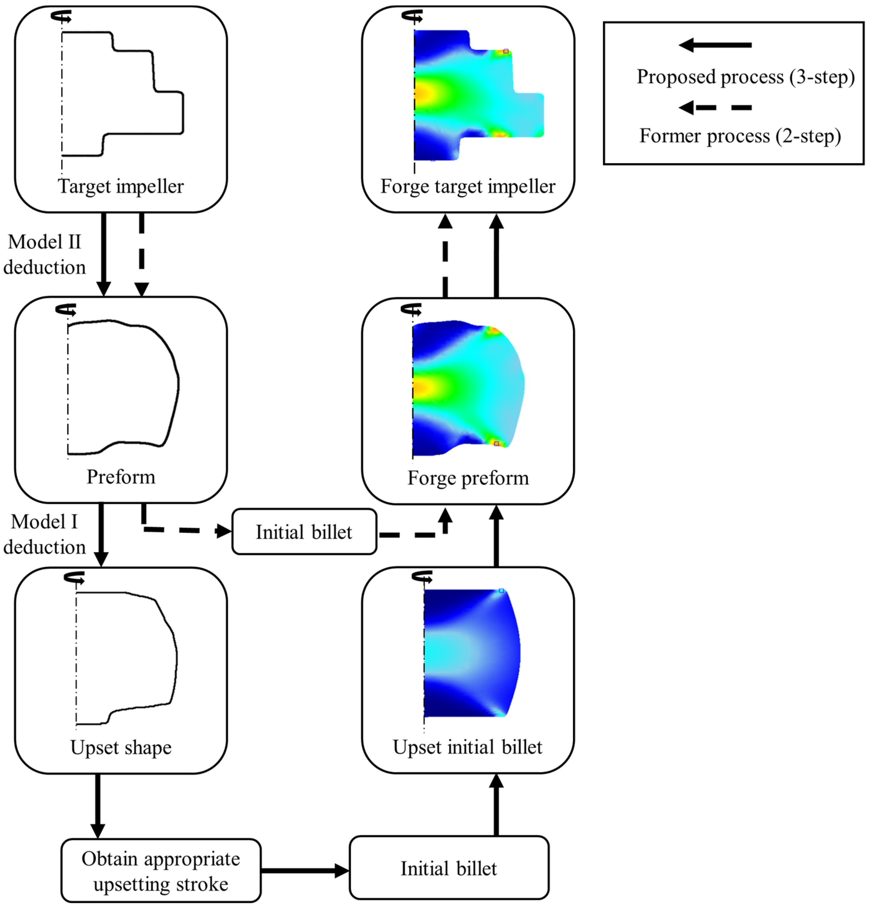
3.1. Overall Process Design

In this study, an additional upsetting process was introduced to the initial billet before the preforming step. CNN model with a structure similar to Figure 3 was utilized to derive appropriate upsetting stroke for the preform shape. The CNN model was applied based on previous studies on preform design [41,42,43] for impeller-forging process. The model is based on the U-net structure [44] and comprises three input images: the final forged shape ( x 1 ), the preform shape obtained through preforming ( x 2 ), and the strain distribution after forging ( x 3 ). The output image is the preform shape ( y ) for the beginning of the forging process. When predicting the preform shape for a specific forging product, the shapes of x 1 and x 2 are inputted the same to prevent underfill defects. Additionally, a zero tensor is inputted to x 3 to aim for uniform strain distribution [25].
The overall design process of the forging process is shown in Figure 4. The entire forging process consists of three steps: upsetting, preform forging, and target impeller forging. Two CNN models based on the structure of Figure 3 were used in this study. One was defined as Model I, which was trained to learn the shape of the upsetting billets as output given the preform shape as input. The other, Model II, was trained to learn the shape of the preform as output given the target impeller shape as input. Using the trained data, Model II can deduce the appropriate preform shape when the target impeller shape is given as input. Subsequently, Model I can deduce the appropriate upset shape when the deduced preform is given as input. Since the upset shape is typically different from the shape obtained by simply upsetting the billet, we proposed upsetting stroke design guidelines to determine the appropriate upsetting stroke. The details of the upsetting stroke design guidelines are described in Section 3.3. After determining the upsetting stroke, the initial billet is upset and forged into a preform. Finally, the target impeller forging is performed, completing the forging process.

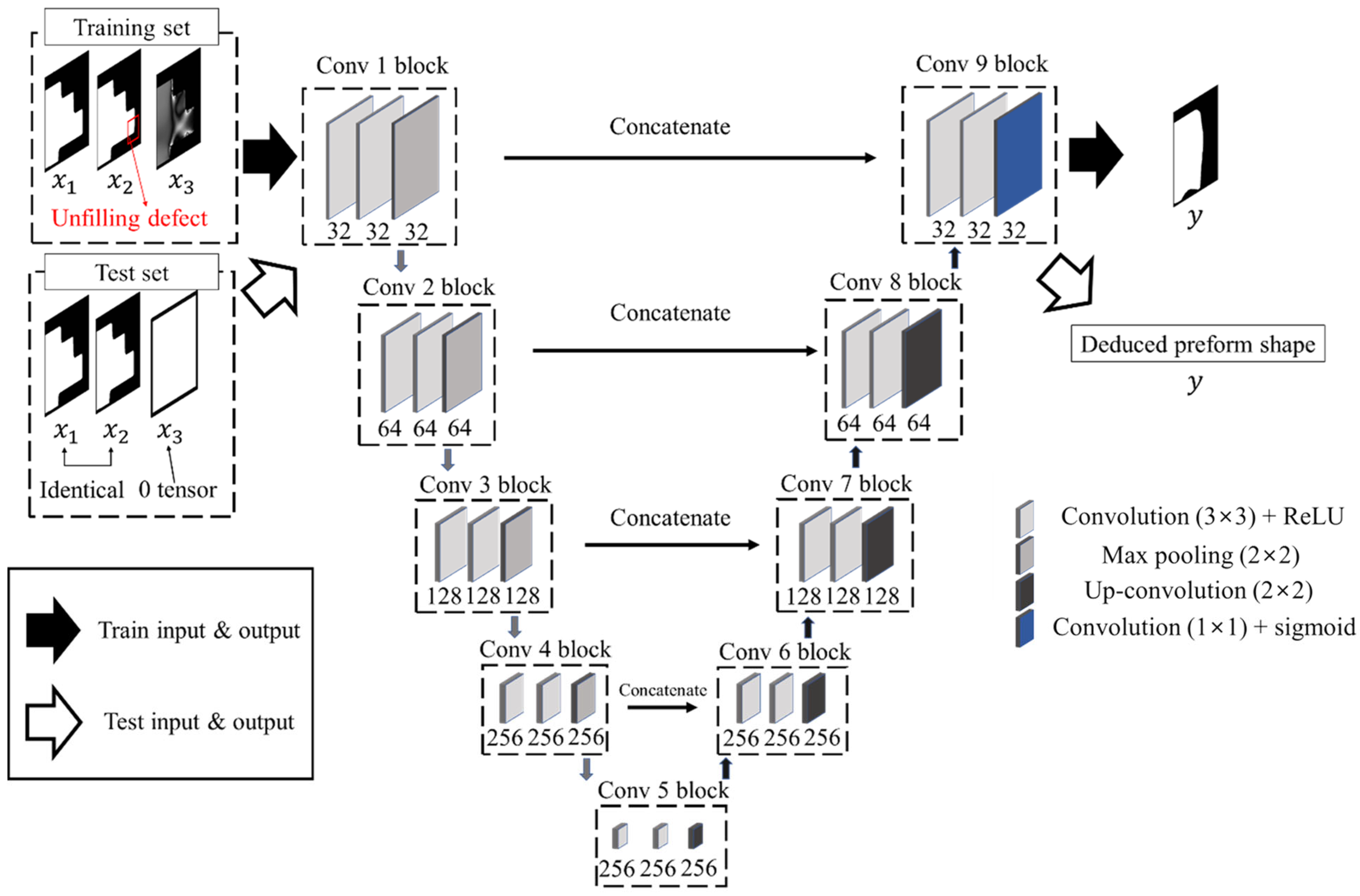
3.2. CNN Training Method

Finite Element Method (FEM) simulation was performed to construct training data for the CNN models in Figure 4. For the simulation, the commercial FEM software, DEFORM 2D version 11.0 from SFTC (Scientific Forming Technologies Corporation, Columbus, OH, USA), was utilized.
The workpiece initial temperature was set to 900 °C for the Ti-6242 material, and the material properties were based on the DEFORM database. The two dies were considered as rigid bodies, with the top die speed maintained at 250 mm/s and a temperature of 250 °C. The initial temperature of the workpiece was set to 900 °C, and a constant Coulomb friction coefficient of 0.35 [45] was implemented for the friction between the dies. The learning influence due to friction and temperature is described in Section 4.4. Von Mises yield criterion and isotropic hardening were applied to the material during deformation. A heat transfer coefficient of 3000 W / ( m 2 · K ) [46] was applied for heat transfer between the workpiece and dies during forging simulation. Three axisymmetric impeller shapes, as shown in Figure 5, were designed for CNN training to provide sufficient training data. All fillet radii were fixed at 5 mm, and the inclination angle was set to 3°.
To construct Model I and Model II, training data for the preform shape should be prepared first. To this end, we conducted upsetting on billets with a volume error of 5% or less, as summarized in Table 1 for each impeller design in Figure 5, with a 5 mm interval. Then, using the impeller design as an input image and the upset billet shape as an output image, we trained the model shown in Figure 3. Subsequently, we obtained five preform shapes for each impeller design in Figure 5 by inputting impeller designs as test inputs, as shown in Figure 6.
In order to design the forging process in Figure 4, the training data were organized as shown in Table 2. There are three types of training data: upset billets, preforms, and impellers, which are organized for each impeller design in Figure 5. In this study, we defined the three sets of training data created for each impeller design as a single training set, and we organized Training set I, Training set II, and Training set III for each of the three impeller designs, respectively.

3.3. Upsetting Stroke Design Guideline

Through deduction using the training sets constructed as shown in Table 2, the upset shape for preform forging is derived. However, the derived shape is generally different from the shape of the billet after upsetting. Therefore, we proposed an upsetting stroke design guideline that can determine the upsetting stroke. First, the maximum diameter ( L 1 ) of the upset shape obtained through the deduction process shown in Figure 4 is measured. Next, the maximum diameter ( L 2 ) of the shape obtained by upsetting the initial billet with the upsetting stroke x is measured. If L 1 and L 2 are equal, x is determined as the appropriate upsetting stroke, and the initial billet is upset by the determined stroke x in the forging process.

4. Result and Discussion

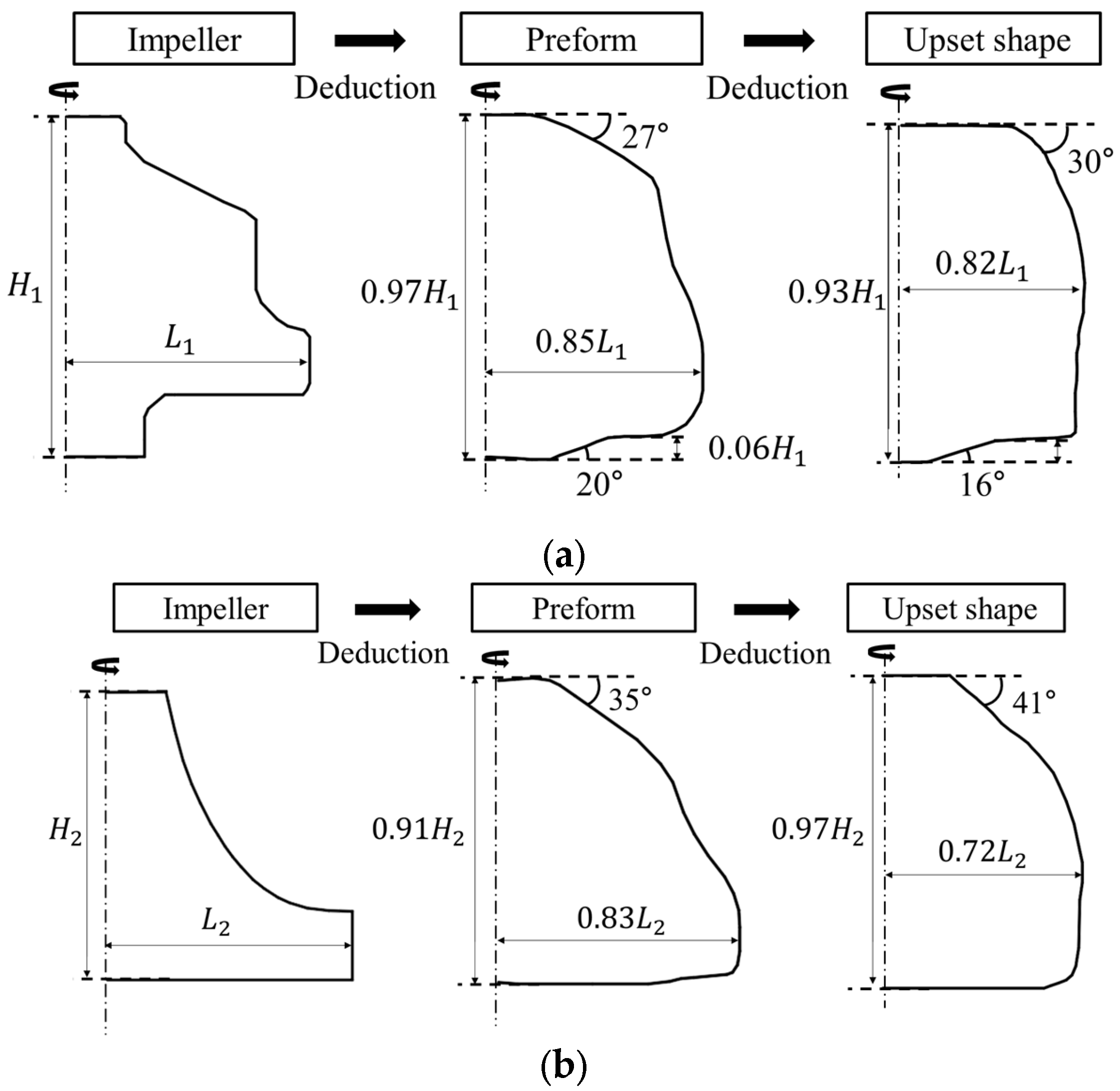
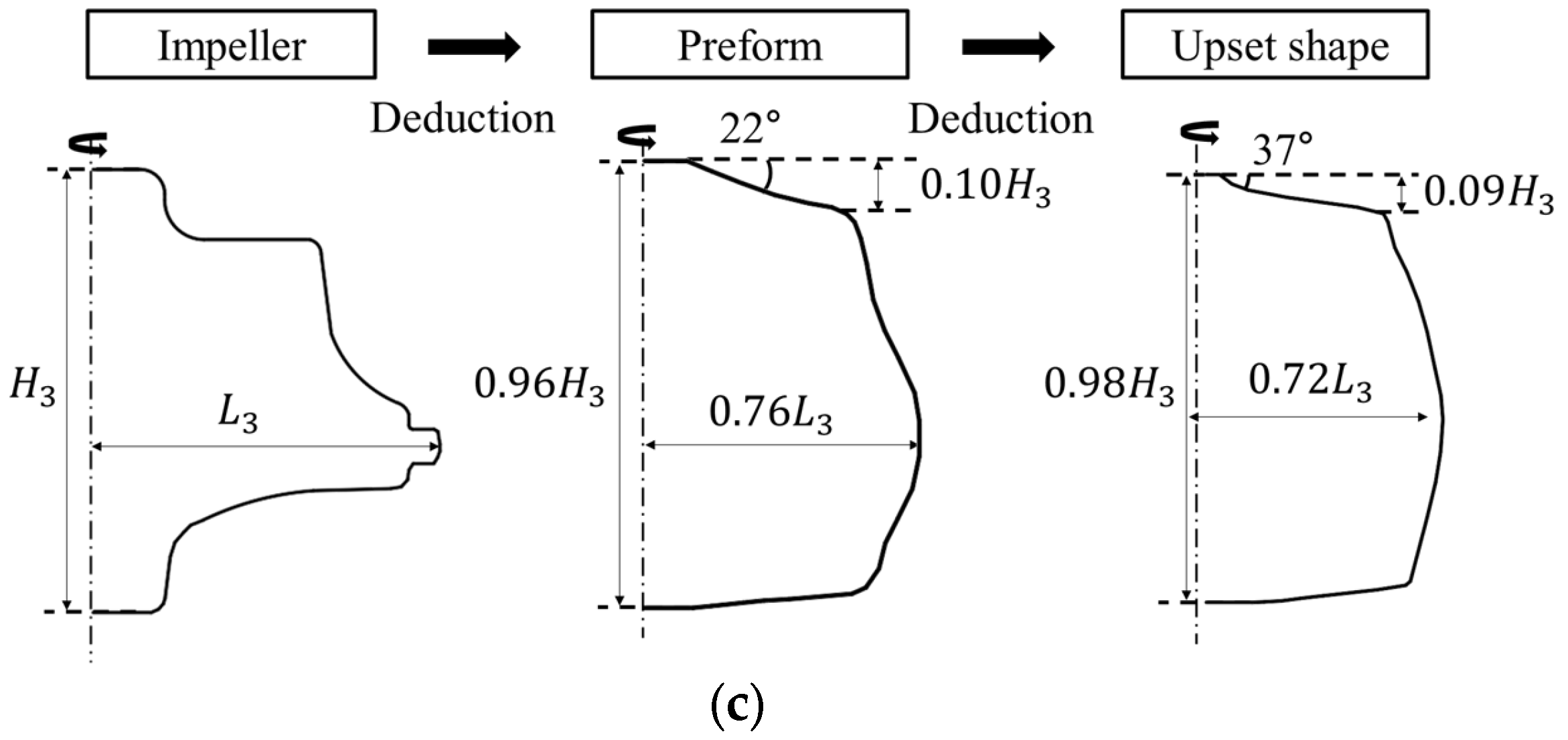
4.1. Preform Designs from Deduction

Using the proposed process design method, preform shape and upset shape were deduced as shown in Figure 4 prior to confirming the final forging results. We performed deductions for Target impellers I, II, and III depicted in Figure 1, and the results are shown in Figure 7. We used NSM former v1.0, which is preform deduction GUI, for deducing preform for target impellers.
After applying the deduction to all three shapes, the preform shape was found to closely resemble the shape of each target impeller, while the upset shape was predicted to resemble the geometry caused by barreling effect that appeared after the billet was upset. This difference is particularly noticeable in Figure 7b, where the preform shape exhibits a protrusion that is similar to the lower part of the target impeller, while the upset shape exhibits a shape that is relatively similar to the barrel shape in the middle section rather than the lower section. Additionally, the maximum height H decreases when impeller is deduced, but increases when the preform is deduced. This can be interpreted as the height increasing to compensate for the decrease in volume due to the diminish of the maximum diameter L, which is predicted to approximate the shape of the billet after it is upset. Moreover, it can be observed that the angle at which the slope occurs in the upset shape, which resembles a cylinder with barreling, tends to decrease compared to that in the preform shape. Based on the upset shape obtained through deduction, the upsetting stroke design guideline presented in Section 3.3 is applied.

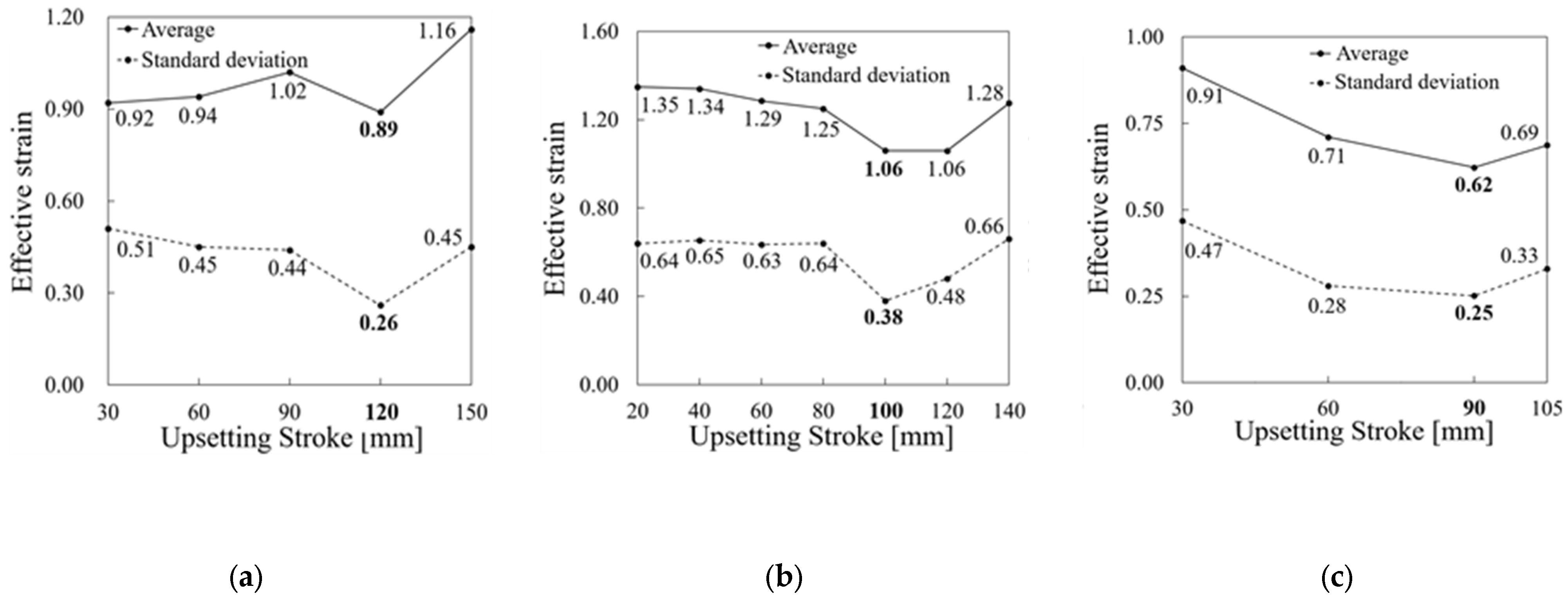
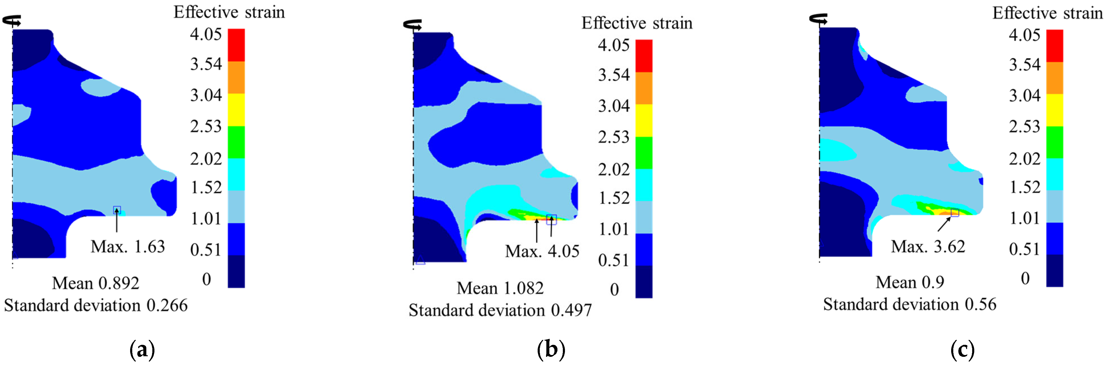
4.2. Validation of Upsetting Stroke Design Guideline

To validate the proposed upsetting stroke design guideline, we applied the guideline to the upset shapes in Figure 7. Applying the guideline to Target impeller I yielded an appropriate upsetting stroke of 120 mm, and the results of the stroke-by-stroke comparison are shown in Figure 8a. For Target impeller II, an appropriate upsetting stroke of 100 mm was determined, and the results of the stroke-by-stroke comparison, as described in Section 3.2, are shown in Figure 8b. Finally, for Target impeller III, an appropriate upsetting stroke of 90 mm was determined, and the results of the stroke-by-stroke comparison are shown in Figure 8c.
The forging results of all three target impellers showed that when upsetting was performed with the stroke determined by the upsetting stroke design guideline, the average strain and standard deviation of the strain were lower than those of other strokes without the guideline. This confirmed that applying the design guideline for the upsetting stroke is effective in achieving uniform distribution of strain in the forged product.

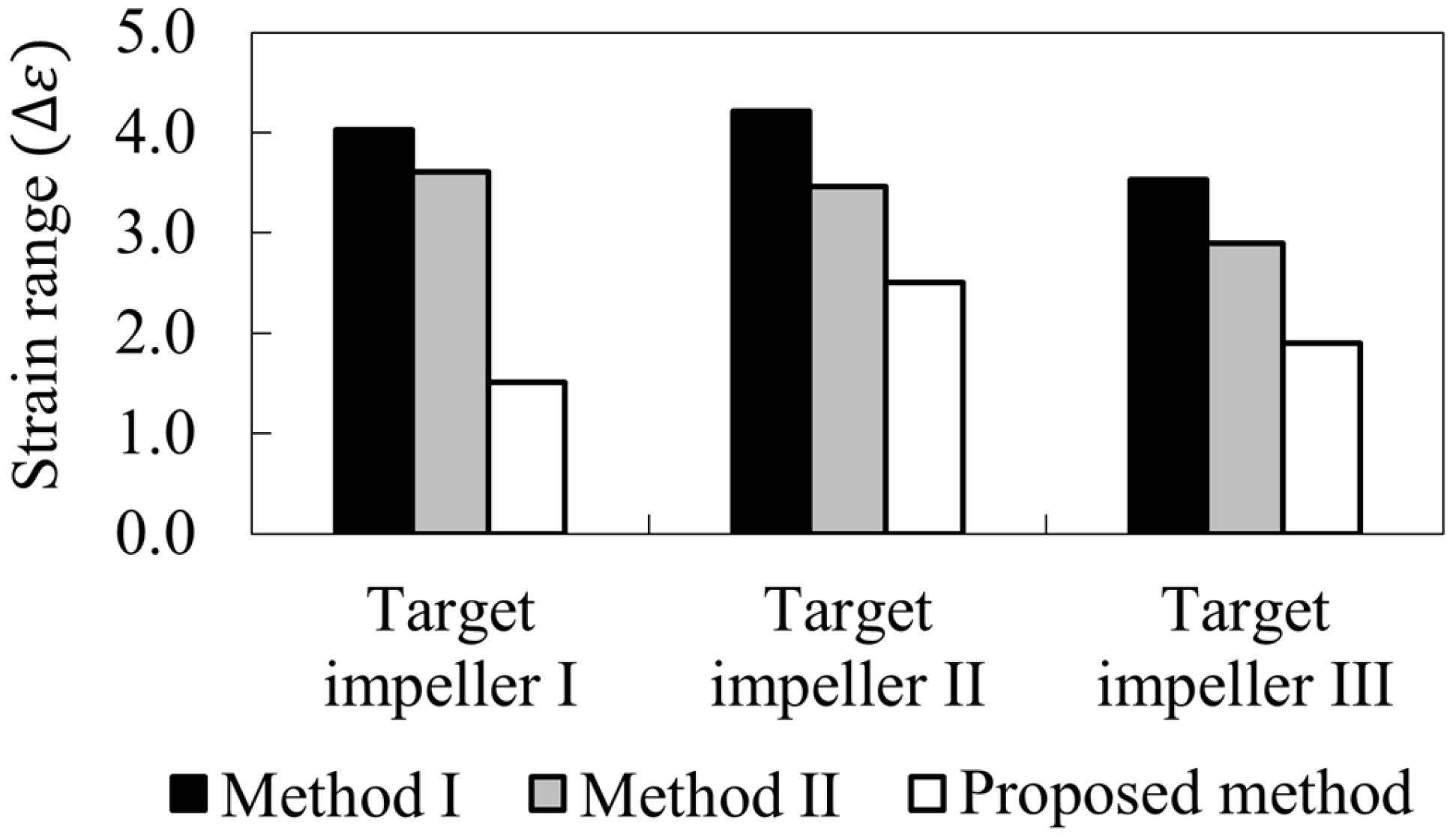
4.3. Validation of Improved Forging Process Design Method

To verify the effectiveness of the suggested method, a comparison was made with Method I and II. Firstly, the comparison was conducted using Target impeller I geometry. The initial billet was upset using the appropriate upsetting stroke derived from Section 3.2, followed by preform forging and final forging to obtain the target impeller as demonstrated in Figure 9a. The two-step forging results using Method I and Method II are shown in Figure 8b,c, respectively. It was found that the proposed method produced a more uniform strain distribution in the target impeller, as evidenced by a 17.5% reduction in mean strain, a 46.4% reduction in strain standard deviation, and a 59.7% reduction in maximum strain compared to Method I. Compared to Method II, the proposed method showed a 0.8% reduction in mean strain, a 52.5% reduction in strain standard deviation, and a 54.9% reduction in maximum strain.
Subsequently, the forging results were compared using Target impeller II geometry. When the appropriate upsetting stroke of 100 mm was used to derive the forging results, the forging of the target impeller using the method proposed in this study is shown in Figure 10a. The results of the two-step forging are shown in Figure 10b when Method I was used, and Figure 10c when Method II was used. When the proposed method was used for forging, it was confirmed that the average strain rate of the target impeller decreased by 15.2% and the standard deviation of strain rate decreased by 45.7% compared to Method I. In addition, the maximum strain rate was also confirmed to have decreased by 40.7%. When the proposed method was compared with Method II, the average strain rate decreased by 18.4%, the standard deviation of the strain rate decreased by 44.1%, and the maximum strain rate decreased by 27.6%.
Finally, the forging results were compared using the geometry of Target impeller III. When using the same method as in the previous cases, the forging results after 90 mm upsetting using the proposed method in this study for the target impeller are shown in Figure 11a. The forging results are shown in two steps in Figure 11b when using Method I and Figure 11c when using Method II. When the proposed method was used for forging, it was found that the mean strain decreased by 38.6% and the strain’s standard deviation decreased by 48.9% compared to Method I. It was also confirmed that the maximum strain decreased by 45.7%. When the proposed method was compared with Method II, the mean strain decreased by 29.5%, the strain’s standard deviation decreased by 48.9%, and the maximum strain decreased by 35.3%.
In all three impeller designs, it was observed that the proposed design method in this study reduced the maximum strain, mean strain, and strain standard deviation, thereby alleviating strain concentration. As shown in Figure 12, the proposed forging process also reduced the strain range compared to Method I and II. However, the strain range still did not meet the required level of 1.2, as stipulated in previous studies [39,40]. Therefore, to meet this requirement, it is necessary to reduce the maximum strain by decreasing it below the minimum strain value that does not result in significant changes in strain values for each method. Consequently, future model modifications should focus not only on achieving uniform strain distribution but also on reducing the maximum strain.

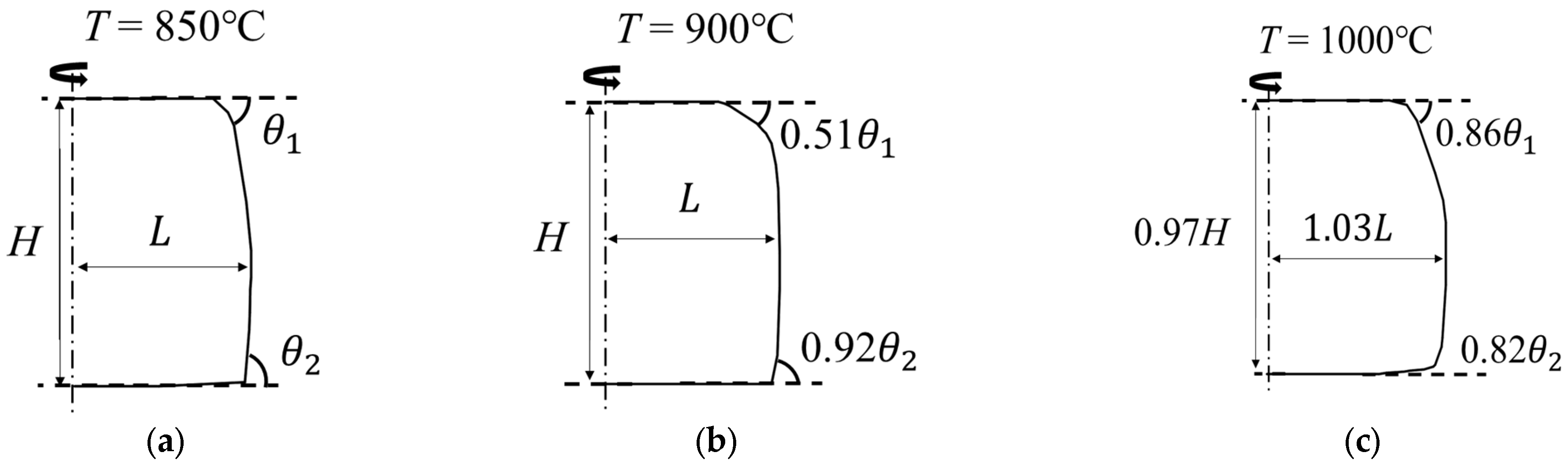
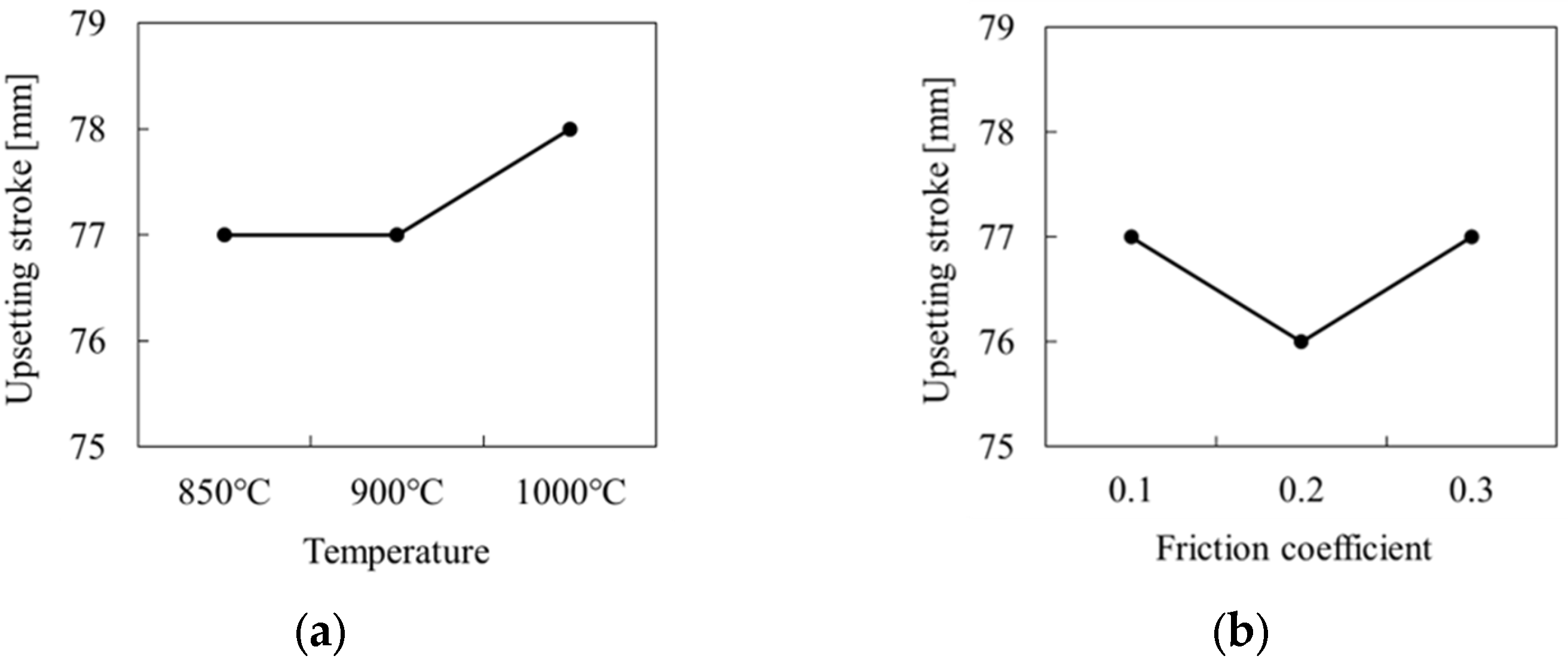
4.4. Discussion for Friction and Initial Temperature Effect

In Section 3.2, the initial temperature was fixed at 900 °C and the value of 0.35 was assigned to the friction coefficient when creating the training data. However, since the temperature and friction during forging can affect the shape of the preform, which is an important factor in determining the strain result of the CNN model, simulations were conducted to examine how temperature and friction effects on the strain results. The temperature and friction were tested in the range of 850–1000 °C and 0.1–0.3 friction coefficient, respectively [47]. The effect of temperature was investigated by fixing the friction coefficient to 0.3, and the effect of friction was investigated by fixing the temperature at 900 °C. Training set II in Table 2 was reorganized and given different temperature and friction conditions than the training data, and a comparison was made for Impeller design II in Figure 5.
Reorganized Training set II was trained and the upset shape for Impeller design II was deduced using the process in Figure 4. The results are presented in Figure 13 and Figure 14. Figure 13 shows the results after setting the friction coefficient to 0.3 and changing the initial temperature to 850 °C, 900 °C, and 1000 °C, while Figure 14 shows the results after fixing the initial temperature at 900 °C and changing the friction coefficients to 0.1, 0.2, and 0.3.
When the initial temperature was varied as shown in Figure 13, the maximum height H did not change when the initial temperature was increased from 850 °C to 900 °C, but decreased by 3% when it was increased to 1000 °C. The maximum radial distance L did not change when the initial temperature was increased from 850 °C to 900 °C, but increased by 3% when it was increased to 1000 °C. Additionally, the maximum angles, θ 1 and θ 2 , decreased by 49% and 8%, respectively, when the temperature was changed from 850 °C to 900 °C, but showed an increasing trend of 69% and a decreasing trend of 11%, respectively, when the temperature was changed from 900 °C to 1000 °C. Consequently, an inverse correlation was observed between the temperature and the maximum height H, as well as angle θ 2 , which means that the increase in temperature resulted in a decrease in both the maximum height H and angle θ 2 . However, no consistent trend was observed for the maximum height H, maximum radial distance L, and angle θ 2 with respect to changes in temperature.
As shown in Figure 14, when modifying the friction coefficient, the maximum height H increased by 2% when the friction coefficient was increased from 0.1 to 0.2, but it decreased again by 2% when the friction coefficient was increased from 0.2 to 0.3. The maximum radial distance L decreased by 1% when the friction coefficient was increased from 0.1 to 0.2, but increased by 2% when the friction coefficient was increased from 0.2 to 0.3. The maximum slope angles θ 1 and θ 2 decreased by 32% and 5%, respectively, when the friction coefficient was increased from 0.1 to 0.2, and by 30% and 7%, respectively, when the friction coefficient was increased from 0.2 to 0.3. Overall, when the friction coefficient was changed, the slope angles θ 1 and θ 2 decreased as the friction coefficient increased. However, in for H and L, we could not see a consistent increasing or decreasing trend as the friction coefficient increased.
Based on the shape derived from Figure 13 and Figure 14, when the upsetting stroke was derived using the upsetting stroke design guidelines in Section 3.3, the result was as shown in Figure 15. In Figure 15a, when the initial temperature was changed, the upsetting stroke remained the same, at 77 mm, when the temperature was changed from 850 °C to 900 °C, but increased by 1 mm to 78 mm when the temperature was increased to 1000 °C. In Figure 15b, when the friction coefficient was changed, increasing it from 0.1 to 0.2 caused the upsetting stroke to decrease by 1 mm from 77 mm to 76 mm, but when increased to 0.3, the upsetting stroke increased again to 77 mm. Consequently, a consistent trend of an increase or decrease in upsetting stroke due to the increase in the initial temperature or friction coefficient was not observed during the derivation of the upsetting stroke.

5. Conclusions

In this study, a forging process consisting of three steps—upsetting, preform forging, and target impeller forging—was designed using a convolutional neural network (CNN) to attain a uniform distribution of strain in the forged product.
-
When applying the upsetting stroke determined by the upsetting stroke design guidelines for the initial billet, the maximum, average, and standard deviation of the strain of the forged target impeller product were minimized compared to other upsetting strokes where the guidelines were not applied.
-
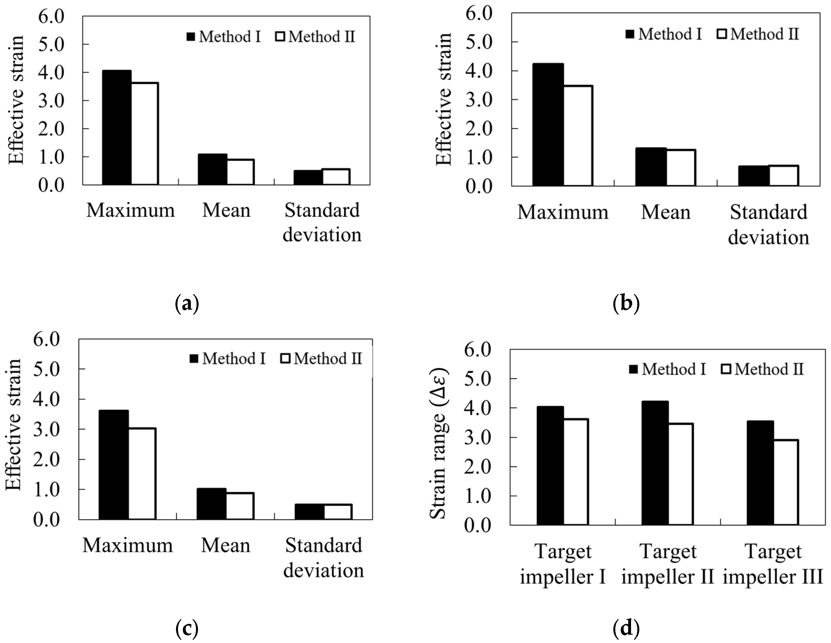
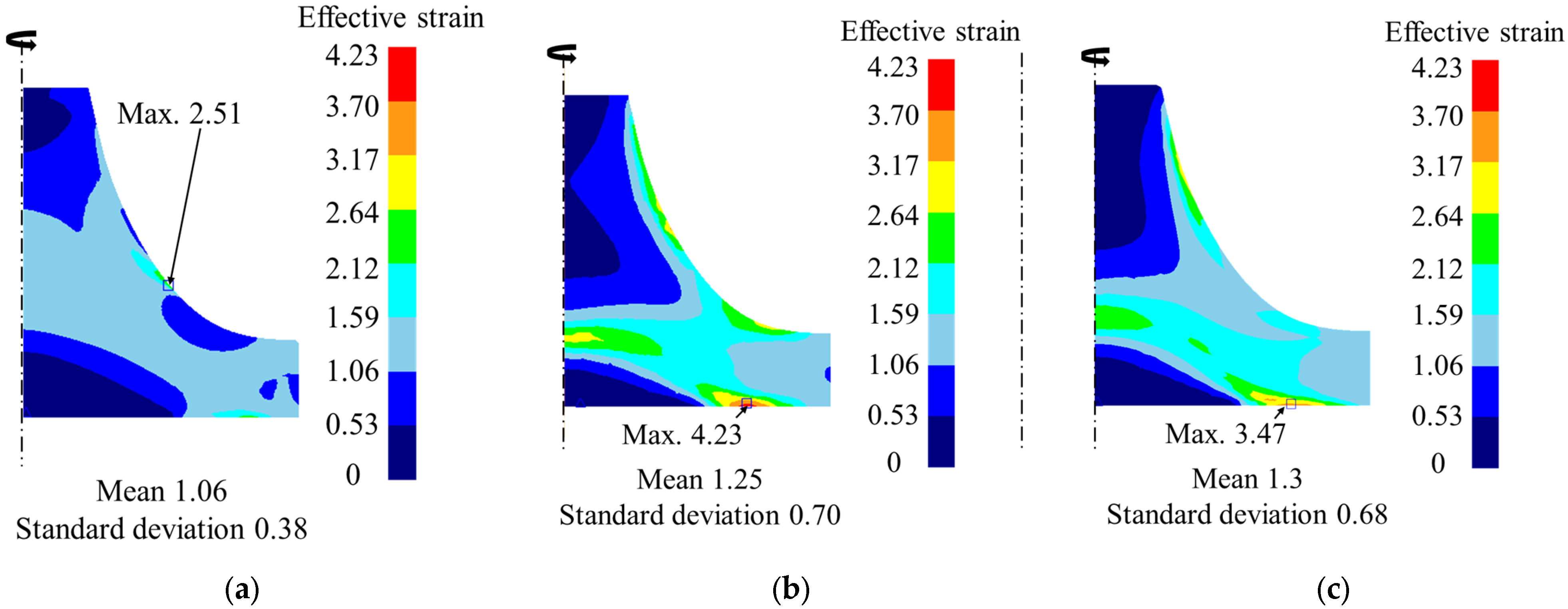
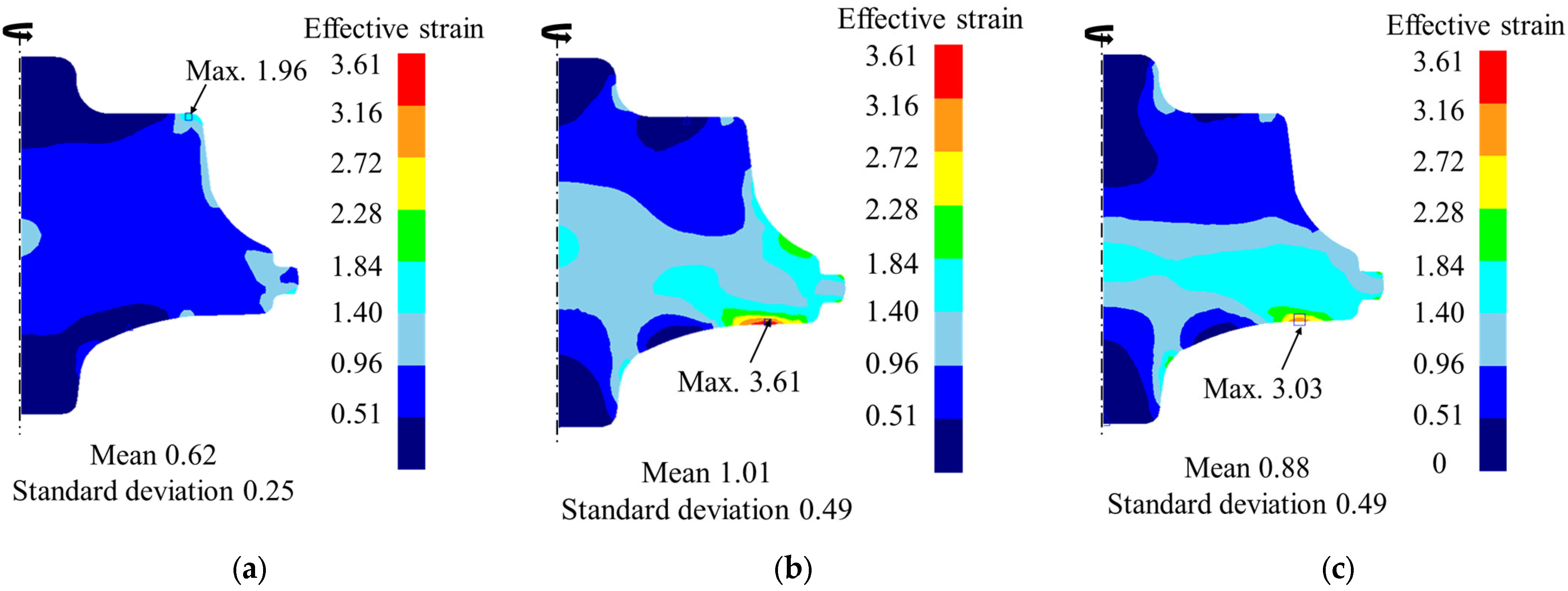
A comparative analysis of the impellers from the original study and those produced using the proposed process showed a significant reduction in the maximum strain, average strain, and standard deviation across three different impeller shapes. This substantial reduction underscores the enhanced efficiency of the proposed forging process, highlighting its superior performance in reducing key strain parameters. The strain range has also been reduced accordingly; however, further modification of the model is essential to achieve a lower strain range and reduce the probability of fatigue crack formation.
-
The proposed impeller-forging process reduces the concentration of strain during forging, thereby reducing the possibility of defects compared to existing processes. Therefore, it is expected that the process design method will be used in fields such as aerospace, where high-quality forging is required.
-
The CNN model used in this study was unable to learn the strain rate changes caused by temperature and friction variations; therefore, we are planning to modify the model to address this issue.

Author Contributions

Conceptualization, N.K.; methodology, K.K. and Y.K.; software, K.K. and Y.K.; validation, K.K., Y.K., Y.J. and I.S.; formal analysis, K.K. and Y.K.; investigation, K.K. and Y.K.; resources, Y.J., I.S. and N.K.; data curation, K.K. and Y.K.; writing—original draft preparation, K.K.; writing—review and editing, K.K. and N.K.; visualization, K.K. and Y.K.; supervision, N.K.; project administration, N.K. and Y.J.; funding acquisition, N.K. All authors have read and agreed to the published version of the manuscript.

Funding

This work was supported by the Korea Research Institute for Defense Technology Planning and Advancement grant funded by the Defense Acquisition Program Administration (DAPA) (No. 20-107-E00-017-03) and the National Research Foundation of Korea (NRF) grant funded by the Korean government (MSIT) (No. 2022R1F1A1066519).

Institutional Review Board Statement

Not applicable.

Informed Consent Statement

Not applicable.

Data Availability Statement

Not applicable.

Acknowledgments

This research was carried out with the help of the ‘HPC Support’ Project, supported by the Ministry of Science, ICT, and NIPA of Korea. This support is gratefully acknowledged.

Conflicts of Interest

The authors declare no conflict of interest.

References

  1. Chamanfar, A.; Pasang, T.; Ventura, A.; Misiolek, W. Mechanical properties and microstructure of laser welded Ti–6Al–2Sn–4Zr–2Mo (Ti6242) titanium alloy. Mater. Sci. Eng. A 2016, 663, 213–224. [Google Scholar] [CrossRef] [Green Version]
  2. Deka, D.; Joseph, D.S.; Ghosh, S.; Mills, M.J. Crystal plasticity modeling of deformation and creep in polycrystalline Ti-6242. Metall. Mater. Trans. A 2006, 37, 1371–1388. [Google Scholar] [CrossRef]
  3. Sefer, B. Oxidation and Alpha–Case Phenomena in Titanium Alloys Used in Aerospace Industry: Ti–6Al–2Sn–4Zr–2Mo and Ti–6Al–4V; Luleå Tekniska Universitet: Luleå, Sweden, 2014. [Google Scholar]
  4. Chen, Y.; Clark, S.J.; Sinclair, L.; Leung, C.L.A.; Marussi, S.; Connolley, T.; Atwood, R.C.; Baxter, G.J.; Jones, M.A.; Todd, I. Synchrotron X-ray imaging of directed energy deposition additive manufacturing of titanium alloy Ti-6242. Addit. Manuf. 2021, 41, 101969. [Google Scholar] [CrossRef]
  5. Hu, Z.; Dean, T. Aspects of forging of titanium alloys and the production of blade forms. J. Mater. Process. Technol. 2001, 111, 10–19. [Google Scholar] [CrossRef]
  6. Zhou, Y.; Zeng, W.; Yu, H. An investigation of a new near-beta forging process for titanium alloys and its application in aviation components. Mater. Sci. Eng. A 2005, 393, 204–212. [Google Scholar] [CrossRef]
  7. Prasad, Y.; Gegel, H.; Doraivelu, S.; Malas, J.; Morgan, J.; Lark, K.; Barker, D. Modeling of dynamic material behavior in hot deformation: Forging of Ti-6242. Metall. Trans. A 1984, 15, 1883–1892. [Google Scholar] [CrossRef]
  8. Lu, B.; Ou, H.; Armstrong, C.; Rennie, A. 3D die shape optimisation for net-shape forging of aerofoil blades. Mater. Des. 2009, 30, 2490–2500. [Google Scholar] [CrossRef]
  9. Yu, G.; Dean, T. A practical computer-aided approach to mould design for axisymmetric forging die cavities. Int. J. Mach. Tool Des. Res. 1985, 25, 1–13. [Google Scholar] [CrossRef]
  10. Bruchanov, A.; Rebelski, S. Closed Die Forging and Warmpressing; VEB Verlag Tcchnik: Berlin, Germany, 1955. [Google Scholar]
  11. Badrinarayanan, S.; Zabaras, N. A sensitivity analysis for the optimal design of metal-forming processes. Comput. Methods Appl. Mech. Eng. 1996, 129, 319–348. [Google Scholar] [CrossRef]
  12. Gao, Z.; Grandhi, R.V. Sensitivity analysis and shape optimization for preform design in thermo-mechanical coupled analysis. Int. J. Numer. Methods Eng. 1999, 45, 1349–1373. [Google Scholar] [CrossRef]
  13. Zhao, G.; Wright, E.; Grandhi, R.V. Sensitivity analysis based preform die shape design for net-shape forging. Int. J. Mach. Tools Manuf. 1997, 37, 1251–1271. [Google Scholar] [CrossRef]
  14. Biswas, S.; Knight, W. Preform design for closed die forgings: Experimental basis for computer aided design. Int. J. Mach. Tool Des. Res. 1975, 15, 179–193. [Google Scholar] [CrossRef]
  15. Vemuri, K.; Oh, S.; Altan, T. BID: A knowledge-based system to automate blocker design. Int. J. Mach. Tools Manuf. 1989, 29, 505–518. [Google Scholar] [CrossRef]
  16. Caporalli, Â.; Gileno, L.A.; Button, S.T. Expert system for hot forging design. J. Mater. Process. Technol. 1998, 80, 131–135. [Google Scholar] [CrossRef]
  17. Kim, C.; Park, C.W. Development of an expert system for cold forging of axisymmetric product: Horizontal split and optimal design of multi-former die set. Int. J. Adv. Manuf. Technol. 2006, 29, 459–474. [Google Scholar] [CrossRef]
  18. Park, J.; Rebelo, N.; Kobayashi, S. A new approach to preform design in metal forming with the finite element method. Int. J. Mach. Tool Des. Res. 1983, 23, 71–79. [Google Scholar] [CrossRef]
  19. Kim, N.; Kobayashi, S. Preform design in H-shaped cross sectional axisymmetric forging by the finite element method. Int. J. Mach. Tools Manuf. 1990, 30, 243–268. [Google Scholar] [CrossRef]
  20. Gao, T.; Yang, H.; Yuli, L. Influence of dynamic boundary conditions on preform design for deformation uniformity in backward simulation. J. Mater. Process. Technol. 2008, 197, 255–260. [Google Scholar] [CrossRef]
  21. Lu, B.; Ou, H.; Cui, Z. Shape optimisation of preform design for precision close-die forging. Struct. Multidiscip. Optim. 2011, 44, 785–796. [Google Scholar] [CrossRef]
  22. Shao, Y.; Lu, B.; Ou, H.; Ren, F.; Chen, J. Evolutionary forging preform design optimization using strain-based criterion. Int. J. Adv. Manuf. Technol. 2014, 71, 69–80. [Google Scholar] [CrossRef]
  23. Ngo, N.; Hsu, Q.; Li, W.; Huang, P. Optimizing design of two-dimensional forging preform by bi-directional evolutionary structural optimization method. Procedia Eng. 2017, 207, 520–525. [Google Scholar] [CrossRef]
  24. Roy, R.; Chodnikiewicz, K.; Balendra, R. Interpolation of forging preform shapes using neural networks. J. Mater. Process. Technol. 1994, 45, 695–702. [Google Scholar] [CrossRef]
  25. Lee, S.; Kim, K.; Kim, N. A preform design approach for uniform strain distribution in forging processes based on convolutional neural network. J. Manuf. Sci. Eng. 2022, 144, 121004. [Google Scholar] [CrossRef]
  26. Lee, S.; Quagliato, L.; Park, D.; Kwon, I.; Sun, J.; Kim, N. A new approach to preform design in metal forging processes based on the convolution neural network. Appl. Sci. 2021, 11, 7948. [Google Scholar] [CrossRef]
  27. Krizhevsky, A.; Sutskever, I.; Hinton, G.E. Imagenet classification with deep convolutional neural networks. Commun. ACM 2017, 60, 84–90. [Google Scholar] [CrossRef] [Green Version]
  28. Shi, K.; Shan, D.; Xu, W.; Lu, Y. Near net shape forming process of a titanium alloy impeller. J. Mater. Process. Technol. 2007, 187, 582–585. [Google Scholar] [CrossRef]
  29. Eylon, D.; Froes, F. Titanium net-shape technologies. JOM 1984, 36, 36–41. [Google Scholar] [CrossRef]
  30. Lee, J.; Kang, S.; Yang, D. Novel forging technology of a magnesium alloy impeller with twisted blades of micro-thickness. CIRP Ann. 2008, 57, 261–264. [Google Scholar] [CrossRef]
  31. Meli, E.; Furferi, R.; Rind, A.; Ridolfi, A.; Volpe, Y.; Buonamici, F. A general framework for designing 3D impellers using topology optimization and additive manufacturing. IEEE Access 2020, 8, 60259–60269. [Google Scholar] [CrossRef]
  32. Prabhu, T.R. Simulations and experiments of the nonisothermal forging process of a Ti-6Al-4V impeller. J. Mater. Eng. Perform. 2016, 25, 3627–3637. [Google Scholar] [CrossRef]
  33. Zhang, M.-Y.; Wang, X.-Y.; Xia, J.-C.; Ji, G. Multiple-target optimization design of pre-forging for gear blank using back propagation neural network and genetic algorithm. Duanya Jishu- Forg. Stamp. Technol. 2010, 35, 22–26. [Google Scholar]
  34. Francavilla, A.; Ramakrishnan, A.C.; Zienkiewicz, O. Optimization of shape to minimize stress concentration. J. Strain Anal. 1975, 10, 63–70. [Google Scholar] [CrossRef]
  35. Gunasekera, J.S. Optimization of Die Design for Forging a TurboCharger Impeller and a Ring Gear Using Process Simulation; Semantic Scholar: Seattle, WA, USA, 2009. [Google Scholar]
  36. Ferreira, F.F.; Neto, D.M.; Jesus, J.S.; Prates, P.A.; Antunes, F.V. Numerical prediction of the fatigue crack growth rate in SLM Ti-6Al-4V based on crack tip plastic strain. Metals 2020, 10, 1133. [Google Scholar] [CrossRef]
  37. Le Biavant, K.; Pommier, S.; Prioul, C. Local texture and fatigue crack initiation in a Ti-6Al-4V titanium alloy. Fatigue Fract. Eng. Mater. Struct. 2002, 25, 527–545. [Google Scholar] [CrossRef]
  38. Peters, J.; Ritchie, R. Influence of foreign-object damage on crack initiation and early crack growth during high-cycle fatigue of Ti–6Al–4V. Eng. Fract. Mech. 2000, 67, 193–207. [Google Scholar] [CrossRef]
  39. Brommesson, R.; Hörnqvist, M.; Ekh, M. Low-cycle fatigue crack growth in Ti-6242 at elevated temperature. Adv. Mater. Res. 2014, 891, 422–427. [Google Scholar] [CrossRef] [Green Version]
  40. Nakamura, H.; Takanashi, M.; Itoh, T.; Wu, M.; Shimizu, Y. Fatigue crack initiation and growth behavior of Ti–6Al–4V under non-proportional multiaxial loading. Int. J. Fatigue 2011, 33, 842–848. [Google Scholar] [CrossRef]
  41. Ko, D.-C.; Kim, D.-H.; Kim, B.-M. Application of artificial neural network and Taguchi method to preform design in metal forming considering workability. Int. J. Mach. Tools Manuf. 1999, 39, 771–785. [Google Scholar] [CrossRef]
  42. Lee, S.; Lee, Y.; Park, C.; Yang, D.-Y. A new method of preform design in hot forging by using electric field theory. Int. J. Mech. Sci. 2002, 44, 773–792. [Google Scholar] [CrossRef]
  43. Tang, Y.-C.; Zhou, X.-H.; Chen, J. Preform tool shape optimization and redesign based on neural network response surface methodology. Finite Elem. Anal. Des. 2008, 44, 462–471. [Google Scholar] [CrossRef]
  44. Ronneberger, O.; Fischer, P.; Brox, T. U-net: Convolutional networks for biomedical image segmentation. In Proceedings of the Medical Image Computing and Computer-Assisted Intervention–MICCAI 2015: 18th International Conference, Munich, Germany, 5–9 October 2015; pp. 234–241. [Google Scholar]
  45. Zhu, Y.; Zeng, W.; Ma, X.; Tai, Q.; Li, Z.; Li, X. Determination of the friction factor of Ti-6Al-4V titanium alloy in hot forging by means of ring-compression test using FEM. Tribol. Int. 2011, 44, 2074–2080. [Google Scholar] [CrossRef]
  46. Hu, Z.; Brooks, J.; Dean, T. The interfacial heat transfer coefficient in hot die forging of titanium alloy. Proc. Inst. Mech. Eng. Part C J. Mech. Eng. Sci. 1998, 212, 485–496. [Google Scholar] [CrossRef]
  47. Semiatin, S.; Seetharaman, V.; Weiss, I. The thermomechanical processing of alpha/beta titanium alloys. JOM 1997, 49, 33–39. [Google Scholar] [CrossRef]
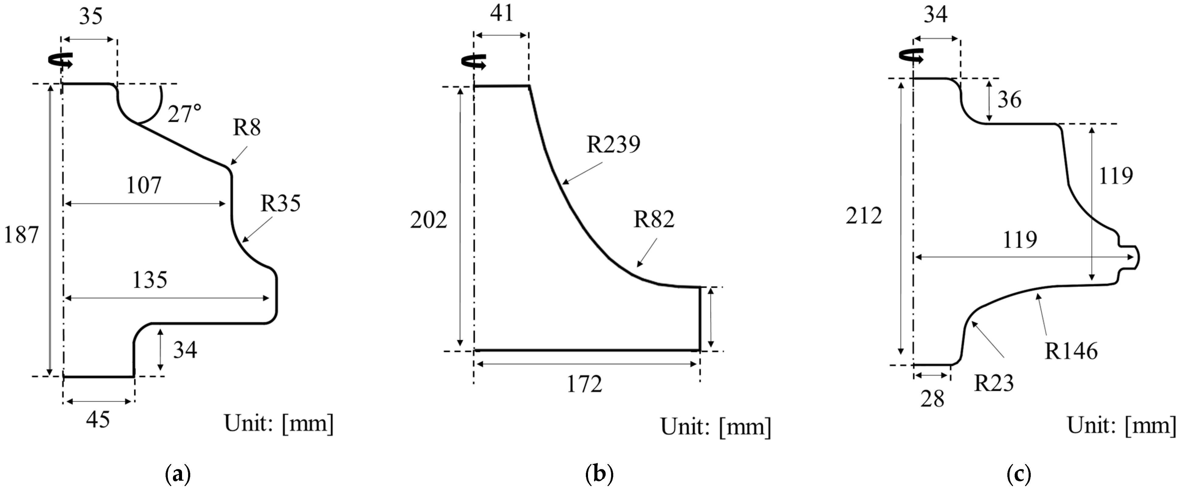
Figure 1. Target impeller shapes studied by: (a) Prabhu [32]; (b) Lee et al. [30]; (c) Gunasekera [35]. From left to right, the shapes were defined as Target Impeller I, Target Impeller II, and Target Impeller III, respectively.
Applsci 13 08272 g001
Figure 2. Result of: (a) Impeller I [32] strain; (b) Impeller II [30] strain; (c) Impeller III [35] strain; (d) strain range(∆ε), applying Method I [30,32,35] and Method II [25]. Strain concentration caused by two-step forging process can be crack propagation factor of Ti-6242 impeller.
Applsci 13 08272 g002
Figure 3. CNN U-net structure used in this study. Nineteen convolutional layers and eight pooling layers are used in U-net structure. Preform shape ( y ) I s derived as a result of 3 input images ( x 1 , x 2 , x 3 ).
Applsci 13 08272 g003
Figure 4. Schematic of impeller-forging process design. In this research, two separate CNN models are utilized to predict the preform shape of the workpiece before the forging process, as per the proposed technique. By inputting the shape of the target impeller, the appropriate upsetting stroke can be determined through deduction. Model I is trained using preform shape as input, upset shape as output. Model II is trained using target impeller shape as input, preform shape as output. Compared to existing design methods, the proposed approach increases the number of process steps by one.
Applsci 13 08272 g004
Figure 5. Impeller design used for CNN model training: (a) Impeller design I; (b) Impeller design II; (c) Impeller design III. We used 3 different designs for constructing training data.
Applsci 13 08272 g005
Figure 6. Preform obtained for each impeller designs: (a) Impeller design I; (b) Impeller design II; (c) Impeller design III. Five preform shapes were obtained for each of the impeller designs.
Applsci 13 08272 g006
Figure 7. Preform and upset shape after deduction for (a) Target impeller I; (b) Target impeller II; (c) Target impeller III.
Applsci 13 08272 g007aApplsci 13 08272 g007b
Figure 8. Variation of effective strain average and standard deviation for case of impeller shapes studied in: (a) Target impeller I; (b) Target impeller II; (c) Target impeller III. In all three cases, forging using the upsetting stroke suggested by the design guideline yielded in the lowest average strain and standard deviation.
Applsci 13 08272 g008
Figure 9. Strain distribution result for Target impeller I forging following: (a) proposed method; (b) Method I; (c) Method II.
Applsci 13 08272 g009
Figure 10. Strain distribution result for Target impeller II forging following: (a) proposed method; (b) Method I; (c) Method II.
Applsci 13 08272 g010
Figure 11. Strain distribution result for Target impeller III forging following: (a) proposed method; (b) Method I; (c) Method II.
Applsci 13 08272 g011
Figure 12. Strain range of applying Method I, II, and proposed method to Impeller I, II, and III. While the proposed forging process reduced the strain range for each impeller design, a model modification that reduces the maximum strain is necessary to meet the level required for defect prevention.
Applsci 13 08272 g012
Figure 13. Upset shapes of Impeller design II after deduction according to temperature changes, with friction coefficients set to 0.3; (a) T = 850 °C; (b) T = 900 °C; (c) T = 1000 °C. As the initial temperature increases, the angle θ 2 tends to decrease, but the maximum height H, angle θ 1 and the maximum radial distance L do not show consistent increases or decreases with increasing initial temperature.
Applsci 13 08272 g013
Figure 14. Upset shapes of Impeller design II after deduction according to friction coefficient changes, with temperatures set to 900 °C; (a) μ = 0.1; (b) μ = 0.2; (c) μ = 0.3. As the friction coefficient increases, the slope angles, θ 1 and θ 2 , tend to decrease, but the maximum height H and the maximum radial distance L do not consistently show an increase or decrease with an increase in the friction coefficient.
Applsci 13 08272 g014
Figure 15. Upsetting strokes for Impeller design Ⅱ determined by upsetting stroke design guidelines for (a) temperature changes, with friction coefficient set to 0.3; (b) friction coefficient changes, with temperature set to 900 °C.
Applsci 13 08272 g015
Table 1. Billet size and upsetting stroke of each impeller design.
Radius [mm]Height [mm]Upsetting Stroke [mm]
Impeller design I98.55295.650–115
Impeller design II83.70251.100–100
Impeller design III106.30318.900–110
Table 2. The number of input and output image for each training set.
InputNumber of Input ImageOutputNumber of Output Image
Model ITraining set IPreform5Upset billet24
Training set II521
Training set III523
Model IITraining set IImpeller1Preform5
Training set II15
Training set III15
Disclaimer/Publisher’s Note: The statements, opinions and data contained in all publications are solely those of the individual author(s) and contributor(s) and not of MDPI and/or the editor(s). MDPI and/or the editor(s) disclaim responsibility for any injury to people or property resulting from any ideas, methods, instructions or products referred to in the content.

