Article

Experimental Study and Numerical Analysis of Flexural Strength of BFRP Bar Concrete Beams Reinforced with Bamboo Fiber and Steel Wire Mesh

College of Civil Engineering, Sichuan Agricultural University, Dujiangyan 611830, China
*
Author to whom correspondence should be addressed.
Appl. Sci. 2022, 12(16), 8001; https://doi.org/10.3390/app12168001
Submission received: 15 July 2022 / Revised: 8 August 2022 / Accepted: 9 August 2022 / Published: 10 August 2022

Abstract

:
To explore the effect of adding bamboo fiber and steel wire mesh to BFRP bar-reinforced concrete beams on their flexural performance, we designed and fabricated six test beams with different parameters. Through flexural tests and numerical simulations, the effects of bamboo fiber length and steel wire mesh layout on the crack resistance, deformation capacity, and flexural ultimate bearing capacity of BFRP bar concrete beams were assessed. The feasibility of the simulation and the calculation method of flexural capacity of such specimens were considered. The research results showed that the addition of bamboo fiber can increase the cracking load and global stiffness and reduce the deformation of the test beam, but this had little effect on the ultimate flexural bearing capacity of the test beam. The cracking load, global stiffness, and ultimate flexural bearing capacity of the test beams were improved by the addition of steel wire mesh, and the stiffness and ultimate flexural bearing capacity of the test specimens with steel wire mesh in the whole beam were improved. Although the composite effect of bamboo fiber and steel wire mesh showed some improvement in these indicators, the improvement effect was not ideal.

1. Introduction

The basalt fiber reinforced plastics bar (BFRP bar) is a new type of material with the advantages of a light weight, corrosion resistance, high tensile strength, and good fatigue resistance. Replacing ordinary steel bars with BFRP bars can effectively solve the shortcomings of steel bars, which easily corrode in concrete structures and add significant structural weight [1]. They are widely used in concrete structures such as bridges, roads, and wharfs [2]. Many experts and scholars have conducted in-depth research and analysis on the failure modes, mechanical properties, and bonding properties of BFRP bar concrete beams [3,4,5,6,7,8]. The low elastic modulus of BFRP bars causes large deformation of the concrete components and an increase of crack widths. The stress–strain relationship of the material is linear, and there are no problems related to brittle failure caused by the yield stage. To a certain extent, the application of its materials in engineering has been limited [9]. The chopped fiber and steel wire mesh composite component could have a significant complementary and reinforcing effect, effectively improving the flexural behavior and crack resistance of the concrete component and improving the brittleness of the matrix material [10,11].
In recent years, global forest coverage and resource storage has been declining, but bamboo has shown a trend of steady growth, indicating that bamboo is a plant material with great potential; and its green, environmentally friendly, and economical features can be recommended. In addition, adding an appropriate amount of bamboo fiber to concrete, like other chopped fibers, could improve the tensile properties of concrete, control the development of early cracks, and significantly improve ductility and toughness [12,13,14,15]. Therefore, this paper took BFRP bar concrete beams reinforced with bamboo fiber and steel wire mesh as the research object, and conducted flexural tests and numerical simulation of the experimental beams by changing the length of the bamboo fiber and the layout of the steel wire mesh. We explored the effects of bamboo fibers and steel wire mesh on the crack development, deformation, and flexural capacity of BFRP bar concrete beams under separate and composite actions, as well as the feasibility of numerical simulation analysis. Analyzing the data of crack resistance, deformation, and flexural behavior, we summarized the best selection method for bamboo fiber length and steel wire mesh layout in concrete, and we established a calculation method for the flexural bearing capacity. This addressed a research vacancy regarding BFRP bar concrete beams reinforced with bamboo fiber and steel wire mesh, and provides a theoretical basis for the engineering applications of these materials.

2. Experimental Program
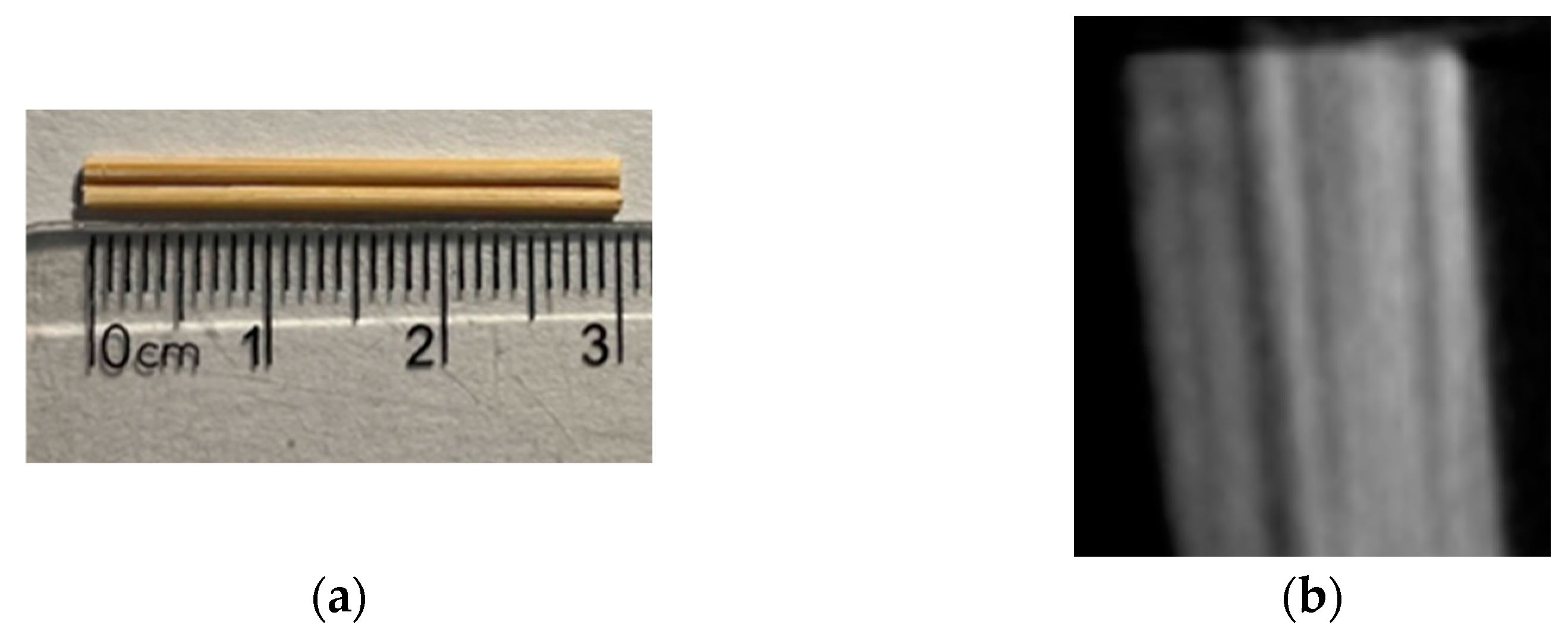
2.1. Materials

The strength grade of the base concrete in this test was C40. The cement was made of P.O42.5R Portland cement produced by Dujiangyan Cement Factory, the coarse aggregate was crushed stone with a particle size distribution ranging from 5 mm to 25 mm, and the fine aggregate was medium sand. The concrete mix ratio is shown in Table 1. The fiber was a typical long thin rod type bamboo fiber. the relevant parameters are shown in Table 2, and the image is shown in Figure 1. The steel mesh was made of woven steel mesh with a diameter of 1 mm and a mesh size of 10 × 10 mm. BFRP bars with a diameter of 20 mm were selected for the longitudinal reinforcement of the specimen, and the relevant mechanical properties are shown in Table 3. The stirrups and the erecting bars were HPB300 steel bars with a diameter of 8 mm.

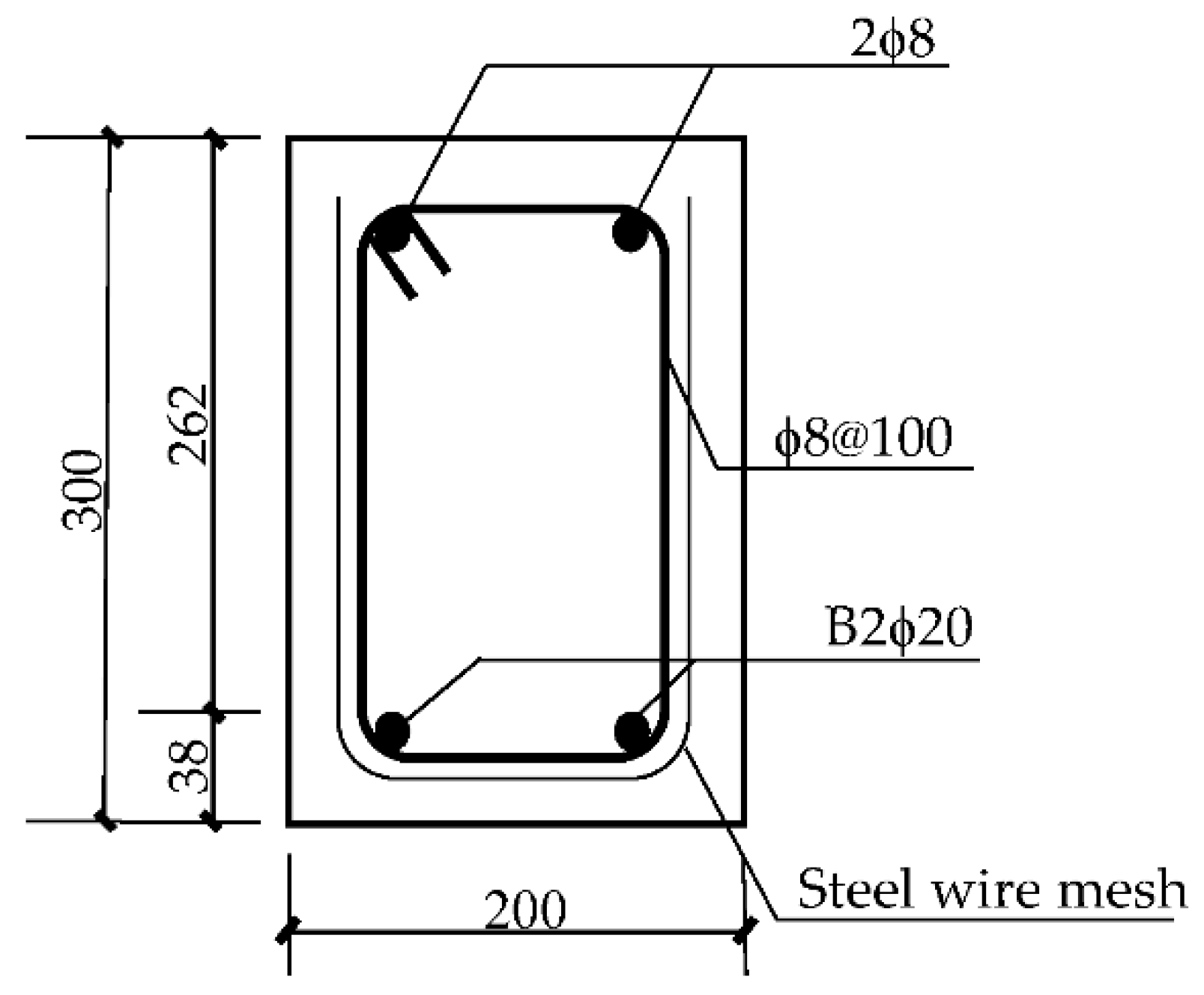
2.2. Test Beam Design

A total of six test beams were designed for the experiment. Section size b × h (section width × section height) were all 200 × 300 mm, the effective height of the cross-section h0 = 262 mm, the span L = 2300 mm, and the calculated span L0 = 2000 mm. According to the literature [12], the volume ratio of bamboo fiber in this paper was selected as 1%. In order to achieve the purpose of bending failure of the test by calculating the reinforcement required to meet the conditions of a suitable reinforcement beam, sufficient stirrups were allocated in the shear span section to ensure that the oblique section of the test beam was not damaged due to insufficient shear capacity during the test. The cross-sectional reinforcement is shown in Figure 2. The steel wire mesh layout and bamboo fiber length of the test beam are shown in Table 4.

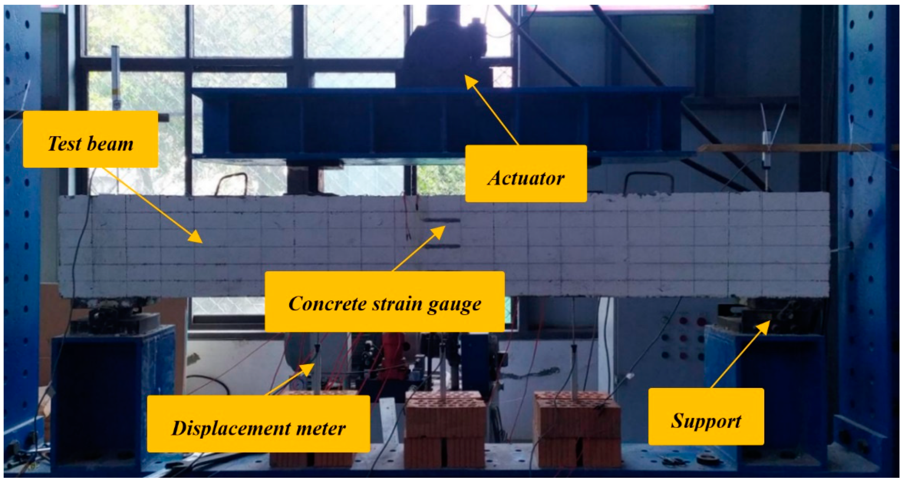
2.3. Arrangement of Measuring Points and Loading Scheme

Reinforcement strain gauges were arranged in the middle of the two BFRP bars at the bottom of the beam and the corresponding positions of the loading points to measure the performance of the BFRP bars. Concrete strain gauges were arranged along the height of the beam mid-span section with an interval of 75 mm. Each beam was pasted with five concrete strain gauges to monitor the strain changes of the concrete. The strain data were collected by a DH3818Y strain tester. Displacement gauges were arranged at the loading point, the middle of the span, and the support to monitor the deformation of the specimens.
The test loading device selected was a 500 kN single-axis electro-hydraulic servo loading system of model ZHP-300B, which uses three-point loading. The test setup is shown in Figure 3. The hierarchical loading system was adopted in the early stage of the test, with the load of each level being 5 kN before cracks and 10 kN after cracks formed. After each level was loaded, the load was held for a period of time in order to observe the crack development and record the strain data. When the beam was loaded until the beam was close to the yield load, the displacement control method was used to load until damage occurred. We used a crack width gauge to observe crack changes.

3. Test Results and Analysis

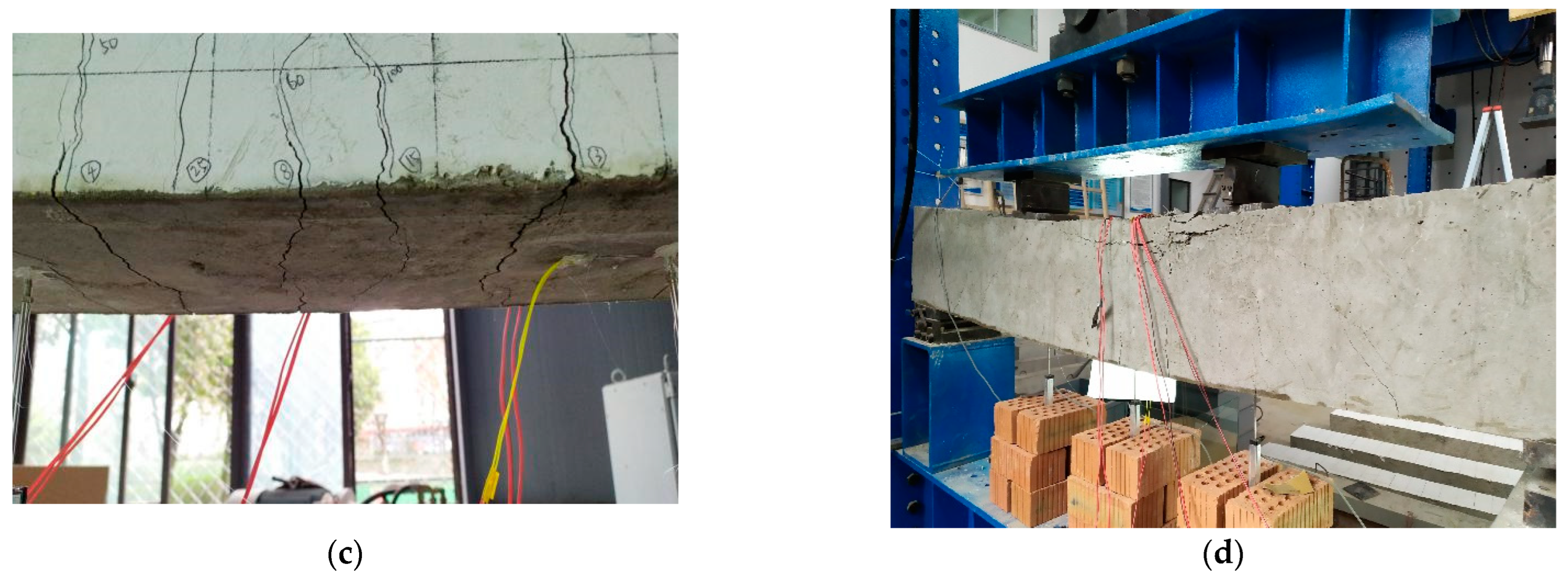
3.1. Test Phenomena and Results

The six test beams all showed flexural failure of the normal section, and the failure mode is shown in Figure 4.
We take L-1-30 as an example to describe the test phenomenon during the loading process. When loaded to 30 kN, tiny vertical cracks appeared in the tension zone of the test beam in the middle of the span. The width measured by the crack width gauge was about 0.05 mm, and the height was about 41 mm, reaching the position of the BFRP bars. When it was loaded to 75 kN, a through crack appeared at the bottom of the beam. With the continuous increase of the load, the cracks continued to extend upwards, and the width continued to increase. At the same time, the number of through cracks at the bottom was increasing, and similar cracks also appeared in areas far from the middle of the span. When the load reached 340 kN, the local area of the concrete compression zone was crushed, the bearing capacity could not continue to increase, and the specimen was destroyed. The maximum crack width of the beam was about 2.8 mm. The height of the compression failure area was 92 mm, and the mid-span deflection was 43 mm. After unloading, the deformation of the beam loading point and the corresponding position in the middle of the span rebounded by 28 mm, 32 mm, and 24 mm from left to right. The crack development and specimen failure of beam L-1-30 are shown in Figure 5.
The concrete mechanical properties (fcu is compressive strength, and ft is split tensile strength), cracking load, and ultimate load of each beam are shown in Table 5.

3.2. Test Analysis

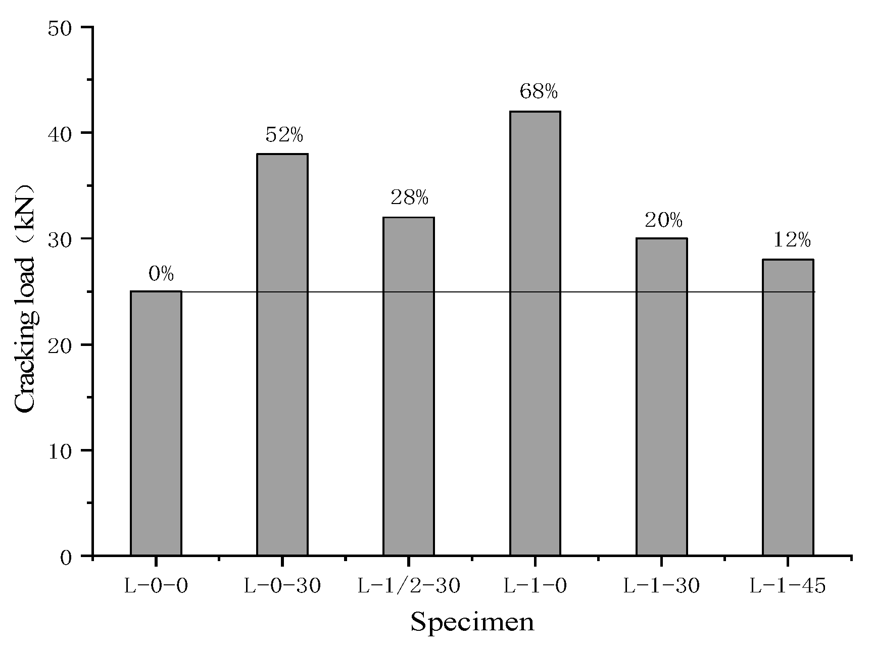
3.2.1. Crack Resistance Analysis

As shown in Figure 6, compared with the BFRP bar concrete beam L-0-0, the addition of bamboo fiber and steel wire mesh can increase the cracking load of the BFRP bar concrete beam to a certain extent. The lifting effect of the two materials alone is obvious. Among them, beam L-0-30 with only bamboo fiber increased by 52%, and beam L-1-0 with only steel wire mesh increased by 68%. However, the lifting effect under the composite action of bamboo fiber and steel wire mesh was not as good as the lifting effect under their separate actions. This is because the fiber length was greater than the size of the steel wire mesh, causing the steel wire mesh to obstruct the passage of bamboo fibers to a certain extent, so that the fiber stuck to the steel wire mesh in the concrete. On the one hand, the fiber is not uniformly distributed in the concrete, which made the tensile performance of the fiber-reinforced concrete specimens unsatisfactory. On the other hand, the sticking of the bamboo fiber also obstructed the enhancement of the tensile performance of the concrete specimen by the steel wire mesh, so the cracking load was reduced in the composite.
Comparing specimens L-1-0, L-1-30, and L-1-45, the cracking load of the test beam decreased with the increase of fiber length. This is because the 45 mm bamboo fiber is longer than the 30 mm bamboo fiber, and the steel wire mesh has a greater obstructing effect on it, so that the effect of improving the tensile performance of the concrete specimen is not ideal and the cracking load is reduced. Comparing specimens L-0-30, L-1/2-30, and L-1-30, the layout of the steel wire mesh in the whole beam section reduced the cracking load of the BFRP bars beam to a certain extent. This is because the concrete at the bottom of the pure bend section in the middle span of the beam undergoes greater tensile stress during bending. When the steel wire mesh is in the whole beam section, the partial tensile stress of the impure bending section is dispersed to the pure bending section, which causes the tensile stress of the pure bending section to further increase under the same load, so the cracking load is reduced.

3.2.2. Deformability Analysis

The deflection of each test beam is shown in Figure 7. Before cracking, the deflection of each specimen was basically the same under the same load, and each test beam was in the elastic deformation stage. The bamboo fiber and steel wire mesh had little effect on the deformation of the beam. After the concrete cracked, the test beam entered the elastoplastic stage. Under the same load, the deflection of the concrete test beam mixed with bamboo fiber and steel wire mesh was small, and, as the load continued to increase, the deformation gap became more obvious. This is because the addition of bamboo fiber and steel wire mesh can share the tensile stress with the concrete therefore preventing the cracks from spreading further. Then, the stress and deformation of the BFRP bars at the cracks are reduced, so that the global stiffness of the beam is improved, and the deflection is significantly reduced. The L-1-0 rigidity improvement effect of the concrete beam with only layout steel wire mesh in the whole beam section was the most obvious.
As shown in Figure 8, comparing specimens L-1-0, L-1-30, and L-1-45, when the layout of the steel wire mesh remained unchanged, along with the increase in the length of the bamboo fiber, the rigidity of the beam was also significantly improved. The 45 mm bamboo fiber had a better improvement effect. This is because the concrete specimens with a bamboo fiber length of 45 mm had a higher tensile strength than 30 mm (as can be seen from ft in Table 5) and were able to bear more tensile stress in the concrete specimens to reduce the deformation of the specimens. Comparing specimens L-0-30, L-1/2-30, and L-1-30, when the length of bamboo fiber remained the same, different steel wire mesh layouts could also significantly affect the deformation of BFRP bar concrete beams. The BFRP bar concrete beam with steel wire mesh in the full beam section showed less deformation, indicating that the steel wire mesh in the full beam section can better connect the cracked concrete specimens into a whole, enhance its integrity, and improve the deformability.

3.2.3. Analysis of Ultimate Flexural Bearing Capacity

As shown in Figure 9, compared with the BFRP bar concrete beam L-0-0, addition of the bamboo fiber in the beam L-0-30 had little effect on the ultimate flexural bearing capacity, showing a small decrease. This is because the ultimate flexural bearing capacity of the test beam is determined by the crushing of the concrete in the compression zone and is affected by the compressive strength of the concrete. When the bamboo fiber is added into the plain concrete specimen, its compressive strength decreases slightly (as can be seen from fcu in Table 5), so the ultimate flexural bearing capacity of the specimen decreases slightly. The flexural ultimate bearing capacity of beam L-1-0 was significantly improved when the steel wire mesh was in the whole beam section, and its ultimate flexural bearing capacity was increased by 16.8%. This is because the steel wire mesh binding was attached to the bottom side and the left and right sides of the rectangular section of the steel frame. The longitudinal steel wires on both sides have the same effect as the longitudinal compression steel bars, thereby enhancing the compressive bearing capacity of the cross section and further enhancing the specimen’s ultimate flexural bearing capacity. However, when bamboo fiber and steel wire mesh are composite in concrete, the improvement of the ultimate flexural bearing capacity is still not ideal, and the reason is the same as the reason for the reduction of crack resistance under composite action.

4. Numerical Simulation

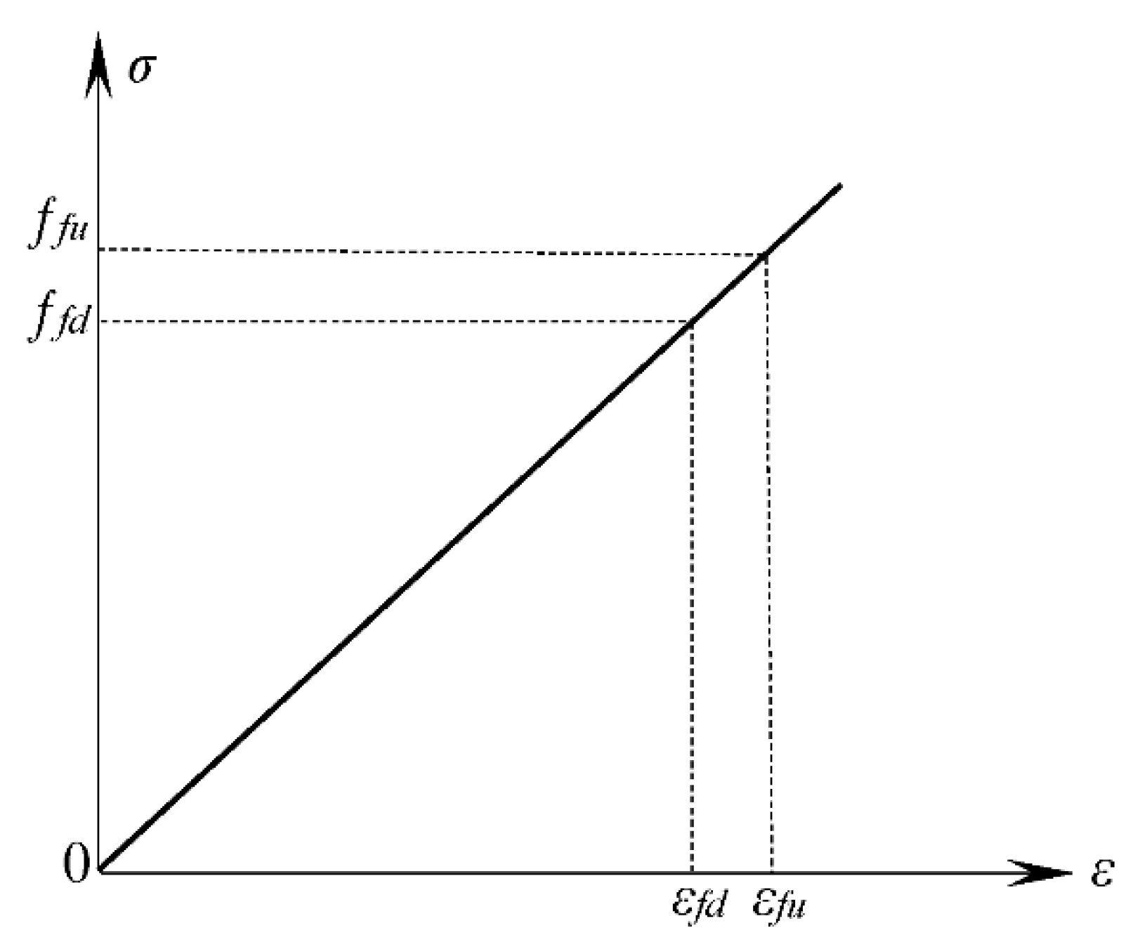
4.1. Material Constitutive Relationship
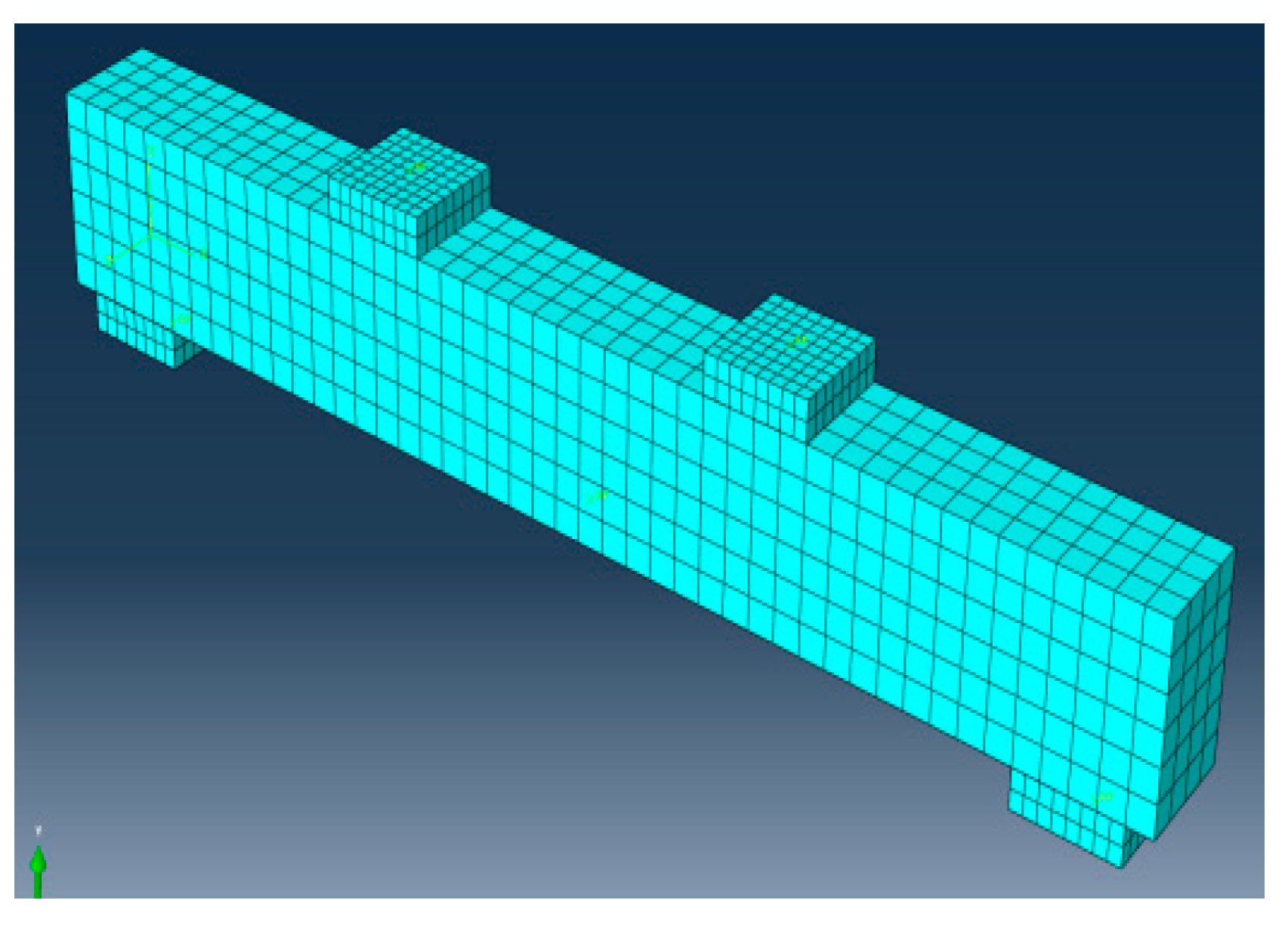
The bamboo fiber concrete adopted the plastic damage model. In integral modeling, the bamboo fiber was dispersed into the concrete and became whole with the concrete, which was considered a continuous homogeneous material. Reference [16] on the constitutive relationship of bamboo fiber concrete, and the uniaxial constitutive relationship suggested in Appendix C of GB50010-2010 “Code for Design of Concrete Structures” [17], were adopted.
The stress–strain relationship of FRP bars [18] is shown in Figure 10, and the function relationship is shown in Equation (1):
σ f = E f ε f     0 ε f ε u
where σf is the stress of the FRP bar, εf is the strain of the FRP bar, Ef is the elastic modulus of the FRP bar, and εu is the ultimate tensile strain of the FRP bar.
The stress–strain relationship of the steel wire mesh is shown in Figure 11 [19], and the function relationship is shown in Equations (2) and (3):
σ s m = E s m ε s m       ε s m ε s m , y
σ s m = σ s m , y           ε s m > ε s m , y
where σsm is the stress of the steel wire mesh, εsm is the strain of the steel wire mesh, and Esm is the elastic modulus of the steel wire mesh.

4.2. Model Building

Figure 12 is a flexural finite element model of BFRP bar concrete beams reinforced with bamboo fiber and steel wire mesh. In the model, the rigid backing plate and concrete specimens at the concentrated load and support all adopted the three-dimensional eight-node linear reduction integral element (C3D8R). BFRP bars and HRB300 erecting bars, stirrups, and steel wire mesh all adopted the two-node three-dimensional linear Truss element (T3D2). The BFRP bars, HRB300 erecting bars, stirrups, and steel wire mesh were connected to form a steel bar skeleton, which was embedded into the concrete, creating the effect of interaction between the two. The rigid backing plate and the concrete beam were tied to avoid concentrated stress. A reference point was established on the rigid backing plate at the loading point, and then the reference point was coupled with the surface of the rigid backing plate to transfer the concentrated force to the model beam. The support at one end of the beam was constrained with X, Y, Z = 0, and the support at the other end was constrained with Y and Z = 0 to make the model beam form a simple supported form. In this paper, the displacement loading method was used for control, and the grid size of the concrete unit was 50 mm, as shown in Figure 13.

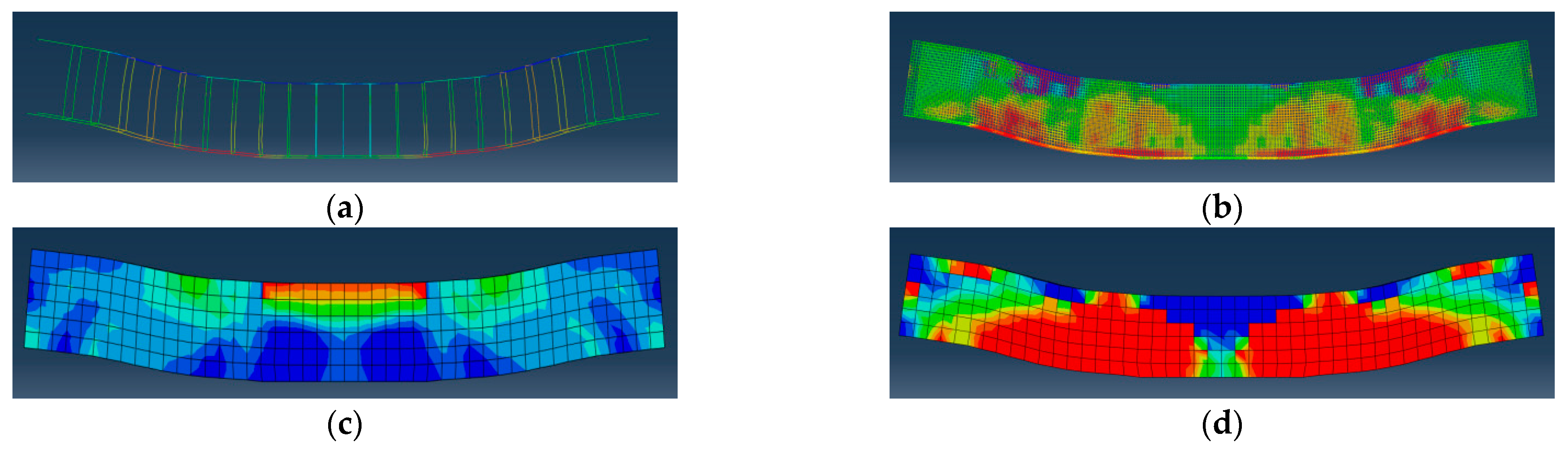
4.3. Analysis of Numerical Results

Taking the L-1-30 beam as an example, the simulation results are shown in Figure 14. Figure 14a,b show that the force of the overall steel frame was fully consistent with the force form of the flexural component. The stress in the area between the support and the loading point was relatively large, almost completely yielding. In Figure 14a,b, most of the mid-span area of the component yielded under tension, and the concrete in the compression zone in Figure 14c was crushed, indicating that the simulated beam was under bending failure. The simulation situation was the same as the test situation; Figure 14d shows the development of simulated beam cracks, which was similar to the development of test beam cracks. The cracks near the loading point were the densest and spread toward the middle of the span and the support.
The deflection test and simulation values of the beam under different loads are shown in Figure 15. In the elastic stage, the slope of the deformation curve of the simulated value was greater than the deformation curve of the test value; that is, the rigidity of the simulated value was greater than the test rigidity. After entering the working stage with cracks, the simulated value and the test value had the same trend. The simulated value entered the failure stage first, but the difference in the ultimate flexural bearing capacity was not large. The simulation and test values of the ultimate flexural bearing capacity of each beam are shown in Table 6.
There was still a certain deviation between the simulation results and the test results, for three main reasons. One is the influence of material parameters. The elastic modulus of concrete was obtained from the stress–strain curve. The ratio of stress to strain is not a constant, but changes with the increase of load. When the concrete enters the plastic working state, its actual elastic modulus will decrease, and the concrete elastic modulus in the numerical simulation is the initial elastic modulus, resulting in higher rigidity than the experimental value. Second, the numerical simulation cannot simulate every link in the test. Both bamboo fiber and BFRP bars are relatively smooth rod-like objects, and relative slippage occurs under load. In the simulation process, the bond–slip relationship between these materials and concrete was not considered, resulting in a certain error in the results. The third is that there is a certain contingency in the production process of the specimen. The boundary conditions in the test and the boundary conditions of the numerical simulation cannot be the same, and, during the test loading process, when the specimen is deformed, the boundary conditions will change accordingly. The result will also change accordingly.
The numerical simulation results of the flexural process of BFRP bar concrete beams reinforced with bamboo fiber and steel wire mesh were in good agreement with the test results, and the error between the test value and the simulated value was mostly within 5%. The errors of the specimens L-1/2-30 and L-1-0 were 15.1% and 14.1%, respectively, but they were still within the allowable error range of the finite element analysis software for simulating concrete structures. This shows the rationality of the numerical simulation calculation model selected in this paper. Therefore, it is feasible to use Abaqus finite element software to analyze the flexural performance of BFRP bar concrete beams reinforced with bamboo fiber and steel wire mesh, as it offers a convenient analysis method for the popularization and application of this type of concrete structure.

5. Flexural Bearing Capacity

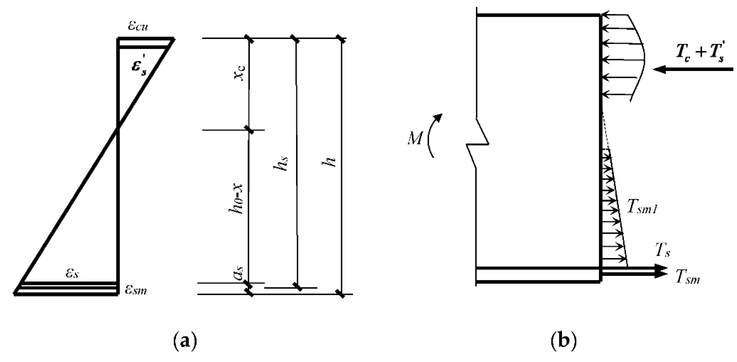
5.1. Calculation Method of Theoretical Value of Flexural Bearing Capacity of the Normal Section

When calculating the flexural bearing capacity of BFRP bar concrete beams reinforced with bamboo fiber and steel wire mesh, the following assumptions need to be made:
  • The section deformation complies with the assumption of a flat section;
  • There will be no relative sliding between the force bar, steel wire mesh, and concrete;
  • The strength of BFRP bars and concrete is determined according to the results of a uniaxial force test, and the elastic modulus of steel wire mesh: E s m = 1.8 × 10 5   MPa ;
  • The influence coefficient of the steel wire mesh on both sides of the beam is obtained according to the literature [19].
The sectional view of the component and related parameters is shown in Figure 16.
Where hsm is the distance from the centroid of the steel wire mesh on the bottom of the stirrup of the component to the edge of the concrete under compression, As is the cross-sectional area of longitudinal steel bars in the tension zone, A s is the cross-sectional area of longitudinal steel bars in the compression zone, Asm is the area of steel wire mesh of the stretched noodles, Asm1 is the area of steel wire mesh of the side face, and as is the vertical distance from the resultant point of all lower longitudinal tensile steel bars on the normal section to the tensile edge of the section.
The stress–strain relationship of the component section is shown in Figure 17. In the figure, ξ h 0 = 0.8 x , T c = f c b ξ h 0 , T s = f y A s , T s = f y A s , T s m = ε s m E s m A s m , ε c u = 0.0033 , where εcu is the ultimate compressive strain of concrete in the compression zone, εs is the strain of the longitudinal steel bar in the tension zone, ε s is the strain of the longitudinal steel bar in the compression zone, Tsm1 is the joint force of the steel wire mesh of the side face, ξ is the relative pressure zone height, x is the concrete compression zone height, Tc is the joint force of concrete in the compression zone, fc is the design value of the concrete axial compressive strength, T s is the joint force of the longitudinal steel bar in the compression zone, f y is the design value of compressive strength of ordinary steel bars, Ts is the joint force of the longitudinal steel bar in the tension zone, fy is the design value of the tensile strength of ordinary steel bars, and Tsm is the joint force of the steel wire mesh of the stretched noodles.
The geometric relationship by the section strain:
ε s m = h s m x x ε c u
Balanced relationship by force:
T c + T s = T s m + T s m 1 + T s
To facilitate the calculation of the formula, we can temporarily ignore the influence of the side steel wire mesh, and the force balance equation can be obtained as follows:
T c + T s = T s m + T s
According to the equivalent rectangular stress diagram:
ξ h 0 = 0.8 x
T c = f c b ξ h 0
T s = f y A s
T s = f y A s
T s m = ε s m E s m A s m
Substituting Formulas (4) and (7)–(11) into (6), we can get:
0.8 f c b x 2 f y A s f y A s ε c u E s m A s m x ε c u E s m A s m h s m = 0
Solving Equation (12), we get:
x = B + B 2 4 A C 2 A
where A = 0.8 f c b , B = f y A s f y A s ε c u E s m A s m , C = ε c u E s m A s m h s m .
Substituting Formula (13) into Formulas (4) and (7) to obtain ε s m and ξ h 0 , and from the torque balance relationship, the theoretical value calculation formula is as follows:
M u = f y A s h 0 ξ h 0 2 + ε s m E s m A s m h s m ξ h 0 2
where Mu is the design value of the flexural capacity of the normal section.
Since the steel wire mesh at the height of 0.5 h above the section of the component has negligible influence on the force performance of the normal section, the crack width and the crack spacing in the pure bending section [20], according to Formula (14), the influence coefficient of the side steel wire mesh can be introduced β [19], Let T s m + T s m 1 = β T s m = β A s m f s m :
M u = f y A s h 0 ξ h 0 2 + β ε s m E s m A s m h s m ξ h 0 2
where fsm is the yield strength of steel wire mesh, β is the influence coefficient of the steel wire mesh of the side face, and β = 0.86 h b .

5.2. Comparative Analysis of the Theoretical Value and the Measured Value

The theoretical calculation values and experimental data values of the flexural bearing capacity of each beam are shown in Table 7.
It can be seen from Table 7 that the measured value of the flexural bearing capacity is nearly 10% higher than the theoretical value, indicating that the theoretical value has a sufficient safety reserve. The calculation results of the theoretical formula established in this paper were in good agreement with the actual test data, indicating that this formula can be used to calculate the flexural bearing capacity of BFRP bar concrete beams reinforced with bamboo fiber and steel wire mesh.

6. Conclusions

In this paper, the flexural test and numerical simulation of BFRP bar concrete beams reinforced with bamboo fiber and steel wire mesh were carried out, and the following conclusions were obtained:
  • The addition of bamboo fiber and steel wire mesh can increase the cracking load of the BFRP bar concrete beam to a certain extent. The lifting effect of the two materials alone is obvious, at 52% and 68%, respectively. However, the lifting effect under the composite action of bamboo fiber and steel wire mesh is not as good as the lifting effect under their separate actions.
  • The addition of bamboo fiber and steel wire mesh can share the tensile stress with the concrete, so that the global stiffness of the beam is improved and the deflection significantly reduced. The L-1-0 rigidity improvement effect of the concrete beam with steel wire mesh only in the whole beam section was the most obvious.
  • The addition of bamboo fiber to the BFRP bar concrete beam causes a small decrease in the flexural ultimate bearing capacity, however it is significantly improved when the steel wire mesh is in the whole beam section; the ultimate flexural bearing capacity is increased by 16.8%. When bamboo fiber and steel wire mesh are composite in concrete, the effect on the ultimate flexural bearing capacity is still not ideal.
  • Based on the experimental and numerical simulation results, a calculation formula for the flexural bearing capacity of the normal section of BFRP bar concrete beams reinforced with bamboo fiber and steel wire mesh was established. The formula is simple in form and the calculated value was in good agreement with the experimental value. It can effectively calculate the flexural bearing capacity of such components and provide a theoretical basis for actual engineering.

Author Contributions

Conceptualization, W.C.; Data curation, H.M.; Funding acquisition, W.C.; Investigation, W.C. and Z.Z. (Zichong Zhu); Methodology, W.C. and Y.Z.; Software, K.Z.; Validation, K.Z.; Writing—original draft, H.M. and Y.Z.; Writing—review & editing, W.C. and Z.Z. (Zuyin Zou). All authors have read and agreed to the published version of the manuscript.

Funding

This research was funded by the Disciplinary Construction Support Plan of Sichuan Agricultural University [grant number 2021993505].

Conflicts of Interest

The authors declare no conflict of interest.

References

  1. Wu, G.; Zhu, Y.; Dong, Z.; Wang, X.; Wu, Z. Experimental study on the corrosion resistance performance of BFRP bars in the alkaline environment. China Civ. Eng. J. 2014, 47, 32–41. [Google Scholar]
  2. Yin, S.; Hua, Y.; Xu, S. Research progress and application of FRP bar concrete structure. J. Build. Struct. 2021, 42, 134–150. [Google Scholar]
  3. Zhu, H.; Cheng, C.; Gao, D.; Cui, G. Bending experimental study and crack width calculation method of high-strength concrete beams reinforced with BFRP bars and steel fiber. J. Build. Struct. 2020, 41, 133–142. [Google Scholar]
  4. Yang, T.; Han, Z.; Deng, N.; Chen, W. Collapse Responses of Concrete Frames Reinforced with BFRP Bars in Middle Column Removal Scenario. Appl. Sci. 2019, 9, 4436. [Google Scholar] [CrossRef] [Green Version]
  5. Rolland, A.; Quiertant, M.; Khadour, A.; Chataigner, S.; Benzar, K.; Argoul, P. Experimental investigations on the bond behavior between concrete and FRP reinforcing bars. Constr. Build. Mater. 2018, 173, 136–148. [Google Scholar] [CrossRef]
  6. Altalmas, A.; Refal, A.E.; Abed, F. Bond degradation of basalt fiber-reinforced polymer (BFRP) bars exposed to accelerated aging conditions. Constr. Build. Mater. 2015, 81, 162–171. [Google Scholar] [CrossRef]
  7. Wang, Z.; Zhao, X.L.; Xian, G.; Wu, G.; Raman, R.K.S.; Al-Saadi, S. Durability study on interlaminar shear behaviour of basalt-, glass- and carbon-fibre reinforced polymer (B/G/CFRP) bars in seawater sea sand concrete environment. Constr. Build. Mater. 2017, 156, 985–1004. [Google Scholar] [CrossRef]
  8. Wu, Z.; Wang, X.; Zhong, J. Advancement of basalt fiber-reinforced polymers (BFRPS) and the novel structures reinforced with BFRPS. Eng. Mech. 2020, 37, 1–14. [Google Scholar]
  9. Ge, W.; Ashour, A.F.; Cao, D.; Lu, W.; Gao, P. Experimental study on flexural behavior of ECC-concrete composite beams reinforced with FRP bars. Compos. Struct. 2019, 208, 454–465. [Google Scholar] [CrossRef] [Green Version]
  10. Sun, Z.; Fu, L.; Feng, D.C.; Vatuloka, A.; Wei, Y.; Wu, G. Experimental study on the flexural behavior of concrete beams reinforced with bundled hybrid steel/FRP bars. Eng. Struct. 2019, 197, 109443. [Google Scholar] [CrossRef]
  11. Xiao, Y.; Wang, Y.; Bi, Y.; Lu, M. Study on Mechanical Performance Tests of RPC Reinforced with Steel Wire Net and Steel Fiber. Acta. Astronaut. 2008, 2, 249–252. [Google Scholar]
  12. Zhang, C. Mechanical Properties and Durability Analysis of Bamboo Fiber Reinforced Concrete; Shanghai Jiao Tong University: Shanghai, China, 2014. [Google Scholar]
  13. Chin, S.C.; Moh, J.N.S.; Doh, S.I.; Mat Yahaya, F.; Gimbun, J. Strengthening of Reinforced Concrete Beams Using Bamboo Fiber/Epoxy Composite Plates in Flexure. Key Eng. Mater. 2019, 821, 465–471. [Google Scholar] [CrossRef]
  14. Zhang, X.; Pan, J.Y.; Yang, B. Experimental Study on Mechanical Performance of Bamboo Fiber Reinforced Concrete. Appl. Mech. Mater. 2012, 174–177, 1219–1222. [Google Scholar] [CrossRef]
  15. Chen, R.; Zeng, J. Pilot Study on the Principal Mechanical Properties of Bamboo Concrete. BRlNrfR 1990, 4, 377–381+431. [Google Scholar]
  16. Xiong, L. Experimental Study on Mechanical Properties of Bamboo Fiber Reinforced Concrete Based on ANSYS; Chengdu University of Technology: Chengdu, China, 2017. [Google Scholar]
  17. Ministry of Construction of the People’s Republic of China. Code for Design of Concrete Structures; China Architecture & Building Press: Beijing, China, 2015. [Google Scholar]
  18. Liang, L. Analysis and Numerical Simulation of Bending for FRP Reinforced Concrete Beams; Xi’an University of Architecture and Technology: Xi’an, China, 2011. [Google Scholar]
  19. Atutis, M.; Valivonis, J.; Atutis, E. Experimental study of concrete beams prestressed with basalt fiber reinforced polymers. Part I: Flexural behavior and serviceability. Compos. Struct. 2018, 183, 114–123. [Google Scholar] [CrossRef]
  20. Ni, B. Experimental Study on Flexural Behavior of Reinforced Concrete Beams with HRB400 Steel Bars and Steel Wire Mesh; Hunan University: Changsha, China, 2007. [Google Scholar]
Figure 1. Bamboo fiber. (a) Bamboo fiber appearance; (b) DR scan image of bamboo fiber.
Applsci 12 08001 g001
Figure 2. Reinforcement drawing of the section.
Applsci 12 08001 g002
Figure 3. Test setup.
Applsci 12 08001 g003
Figure 4. Failure mode of the test beams. (a) L-0-0; (b) L-0-30; (c) L-1/2-30; (d) L-1-0; (e) L-1-30; (f) L-1-45.
Applsci 12 08001 g004aApplsci 12 08001 g004b
Figure 5. Beam L-1-30 experimental phenomena. (a) Development of cracks on the front of beam L-1-30; (b) the concrete on the upper part of the beam L-1-30 is crushed; (c) a through crack at the bottom of beam L-1-30; (d) development of cracks on the back of beam L-1-30.
Applsci 12 08001 g005aApplsci 12 08001 g005b
Figure 6. Comparison of the cracking load of each specimen.
Applsci 12 08001 g006
Figure 7. Comparison of the deformation of each test beam.
Applsci 12 08001 g007
Figure 8. Comparison of test beam deformation under different loads.
Applsci 12 08001 g008
Figure 9. Comparison of the ultimate load of each specimen.
Applsci 12 08001 g009
Figure 10. Stress–strain of the FRP bar.
Applsci 12 08001 g010
Figure 11. Stress–strain of the steel wire mesh.
Applsci 12 08001 g011
Figure 12. Finite element model.
Applsci 12 08001 g012
Figure 13. Mesh generation.
Applsci 12 08001 g013
Figure 14. Stress contours and damage contours. (a) The stress contours of the steel frame when the specimen yields under tension; (b) the stress contours of the steel wire mesh when the specimen yields under tension; (c) stress contours when concrete is crushed in the compression zone; (d) the damage contours of the concrete when the specimen yields under tension.
Applsci 12 08001 g014
Figure 15. Comparison of load-deflection curves of test beam and simulated beam. (a) Beam L-0-0; (b) Beam L-0-30. (c) Beam L-1/2-30; (d) Beam L-1-0; (e) Beam L-1-30; (f) Beam L-1-45.
Applsci 12 08001 g015
Figure 16. Component cross section.
Applsci 12 08001 g016
Figure 17. Cross-sectional stress and strain distributions of the component. (a) Cross-sectional strain distribution; (b) cross-sectional stress distribution.
Applsci 12 08001 g017
Table 1. Mixture ratio of the concrete.
Water (kg/m3)Cement (kg/m3)Crushed Stone (kg/m3)Medium Sand (kg/m3)
1854201273572
Table 2. Performance parameters of the bamboo fiber.
MaterialFiber Diameter (mm)Fiber Length (mm)Density (kg/m3)
Bamboo fiber1.530/45848.826
Table 3. Mechanical properties of the BFRP bars.
Diameter (mm)Tensile Strength (MPa)Elastic Modulus (GPa)
201010.7744
Table 4. Parameters of the test beams.
SpecimenSteel Wire Mesh LayoutBamboo Fiber Length (mm)
L-0-0-0
L-0-30-30
L-1/2-30Between the 1/2 maximum bending moment points30
L-1-0The whole beam section0
L-1-30The whole beam section30
L-1-45The whole beam section45
Table 5. Concrete mechanical properties, cracking load, and ultimate load of specimens.
Specimenfcu (MPa)ft (MPa)Cracking Load (MPa)Ultimate Load (MPa)
L-0-045.13.0625340
L-0-3043.23.2338329
L-1/2-3043.23.2332284
L-1-045.13.0642397
L-1-3043.23.2330340
L-1-4544.53.9428343
Table 6. Simulation value and test value of the flexural ultimate bearing capacity.
SpecimenTest Value (kN)Simulation Value (kN)(Simulation Value − Test Value)/Test Value (%)
L-0-03403420.6
L-0-303293300.3
L-1/2-3028432715.1
L-1-0397341−14.1
L-1-30340335−1.5
L-1-45343339−1.2
Table 7. Comparative analysis of the theoretical value M u c and the measured value M u 0 of the bending capacity.
Specimen Theoretical   Value   M u c   ( kN · m ) Measured   Value   M u 0   ( kN · m ) M u 0 M u c M u 0 × 100   ( % )
L-0-088.1102.013.6
L-0-3084.698.714.3
L-1/2-3084.885.20.5
L-1-098.5119.117.3
L-1-3090.3102.011.5
L-1-4591.7102.910.9
Note: The measured value of the flexural bearing capacity is obtained by the calculation method of the beam bending moment in the material mechanics.
Publisher’s Note: MDPI stays neutral with regard to jurisdictional claims in published maps and institutional affiliations.

