
Improved SPGD Algorithm for Optical Phased Array Phase Calibration

 , and
, and 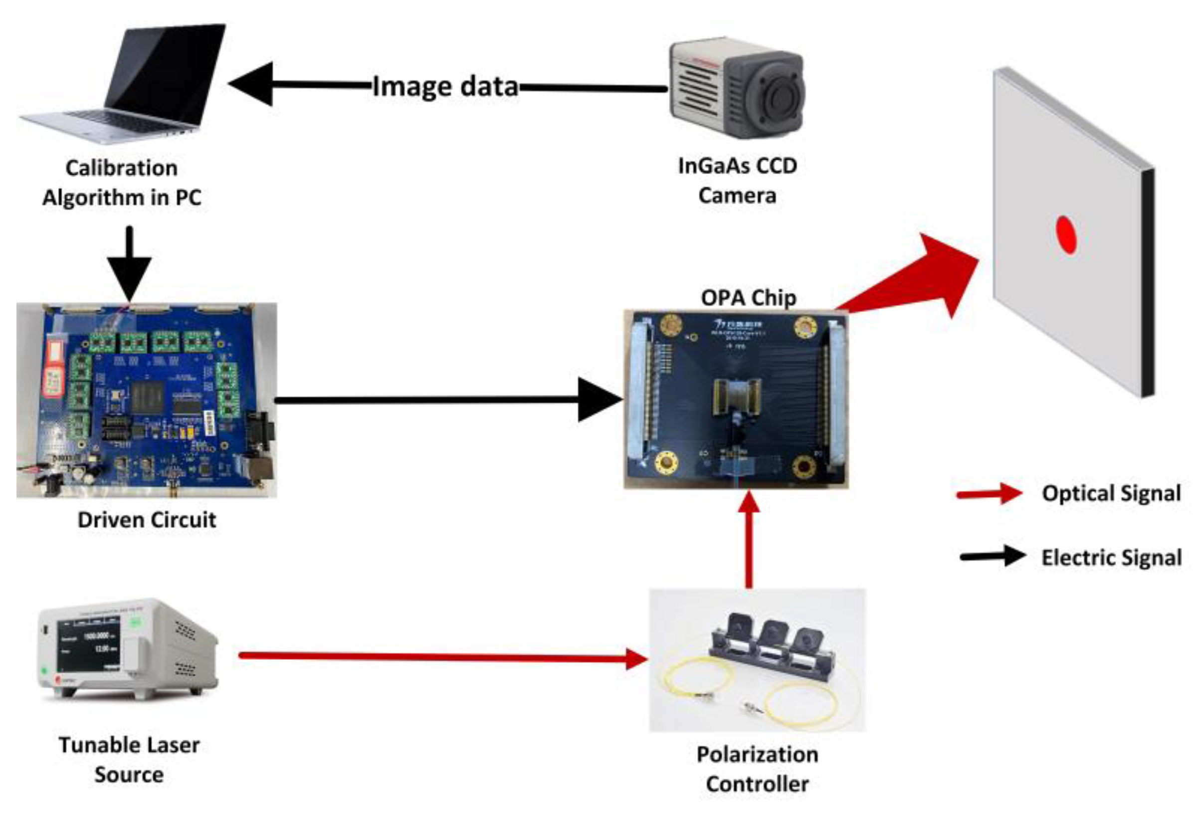
Abstract
:1. Introduction
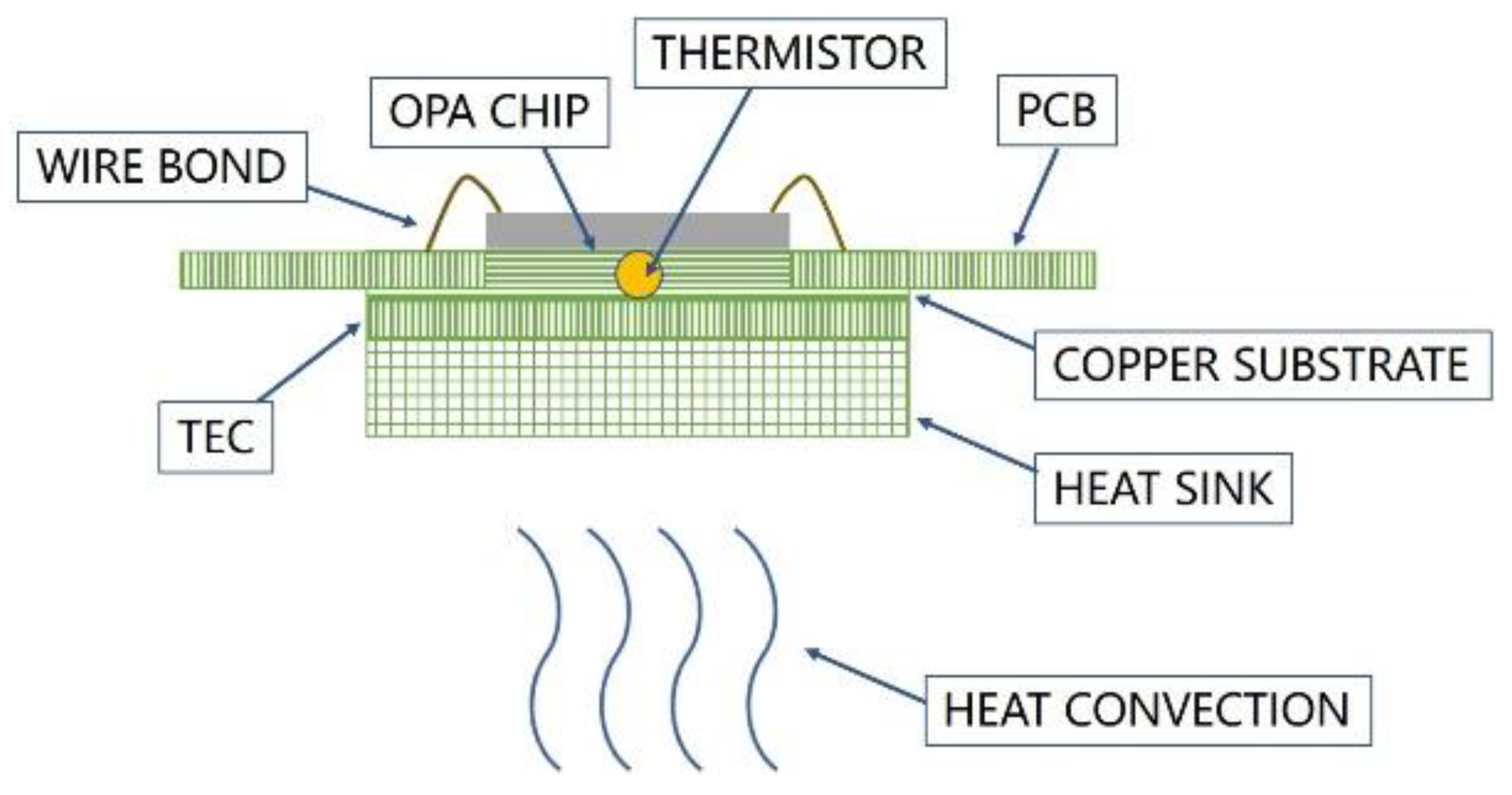
2. OPA Characteristics and System Construction
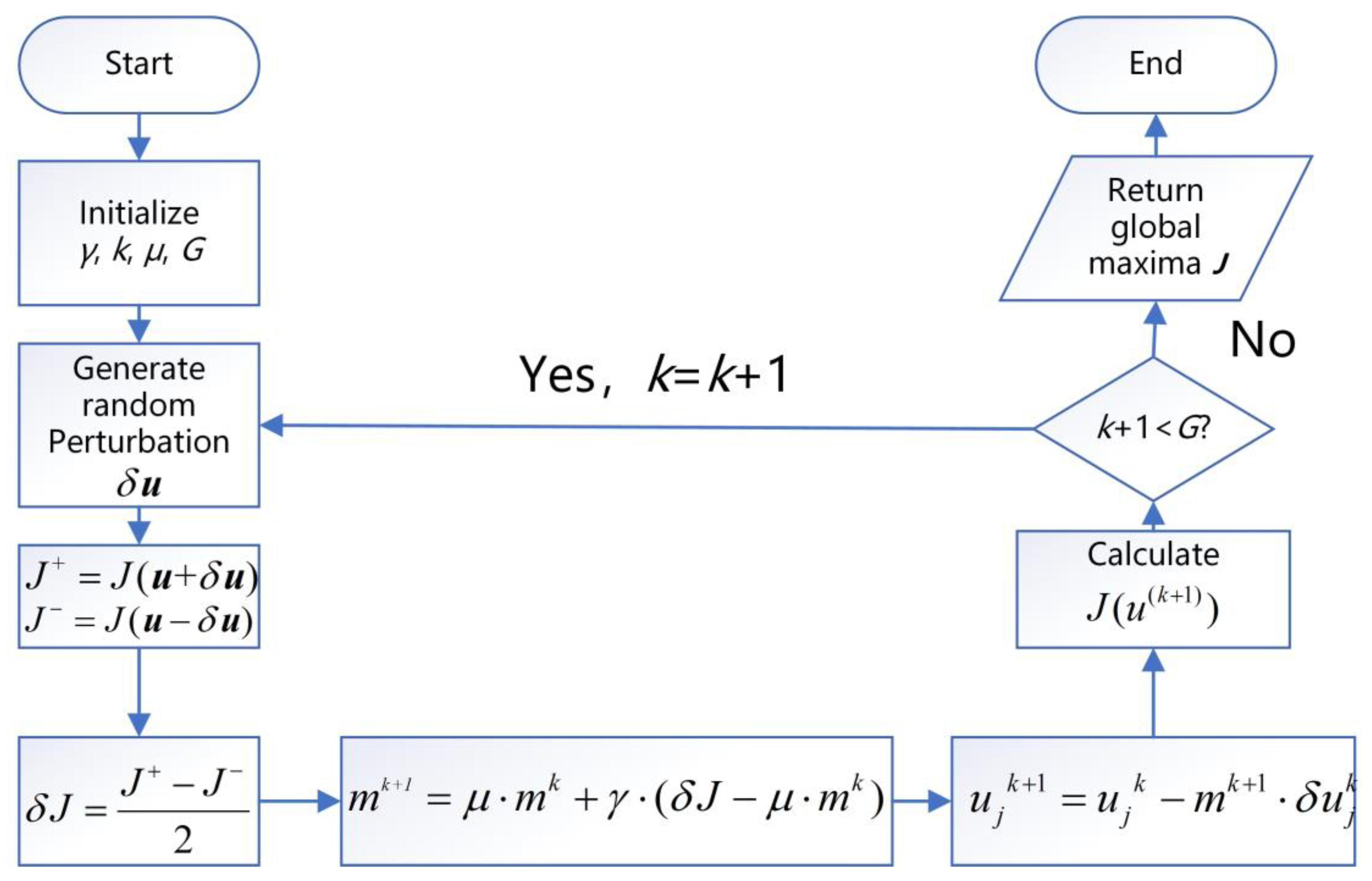
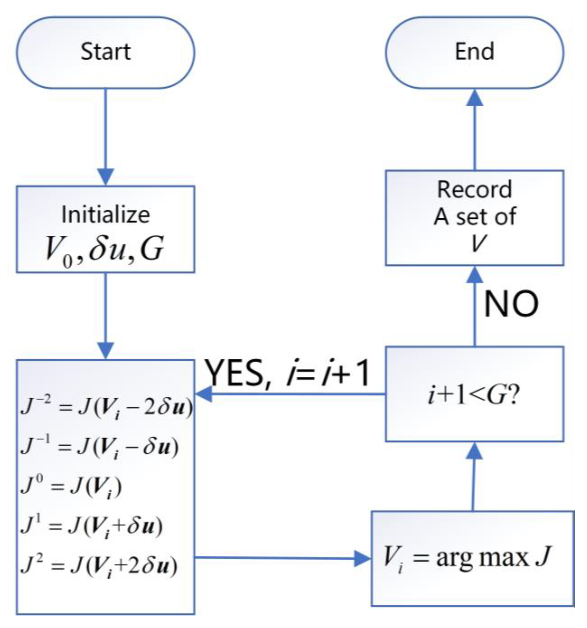
3. Calibrating Algorithm
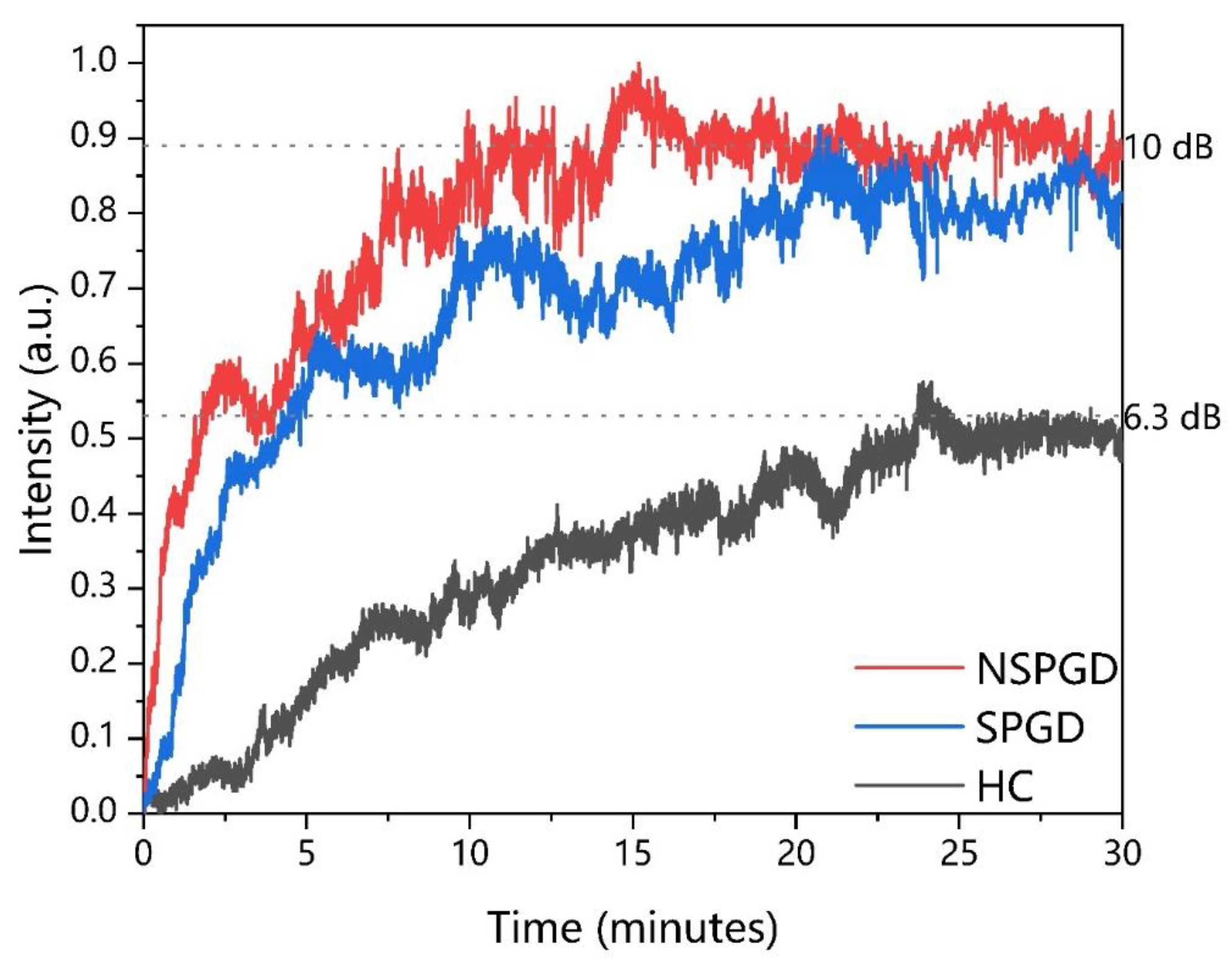
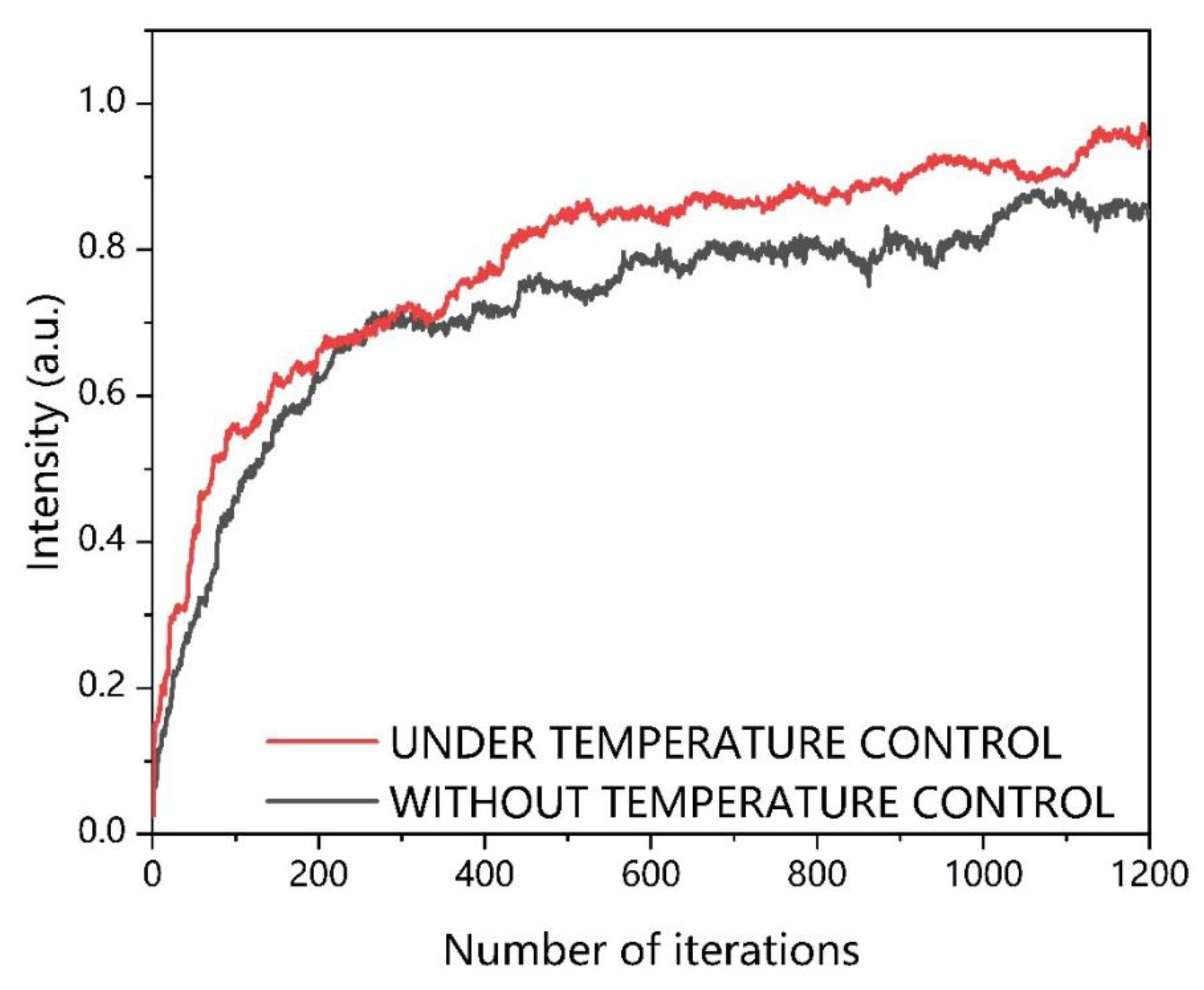
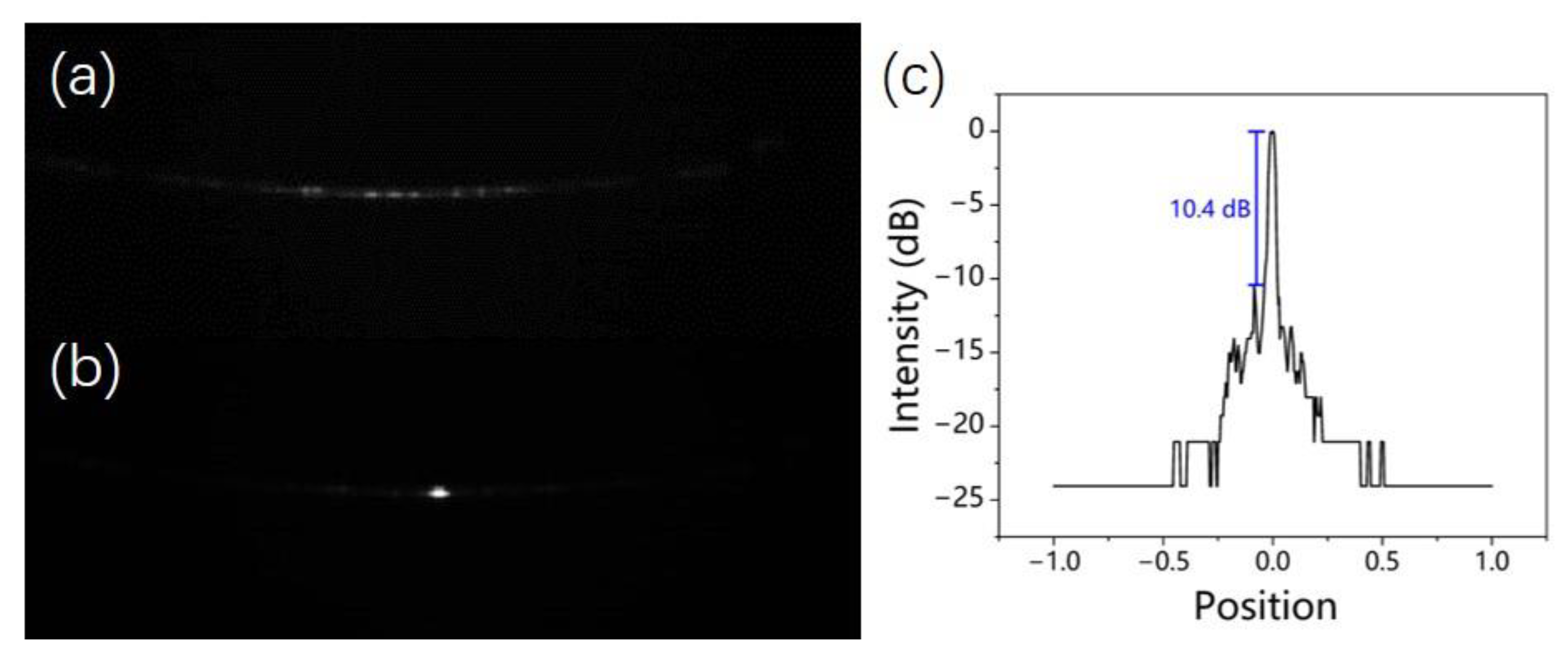
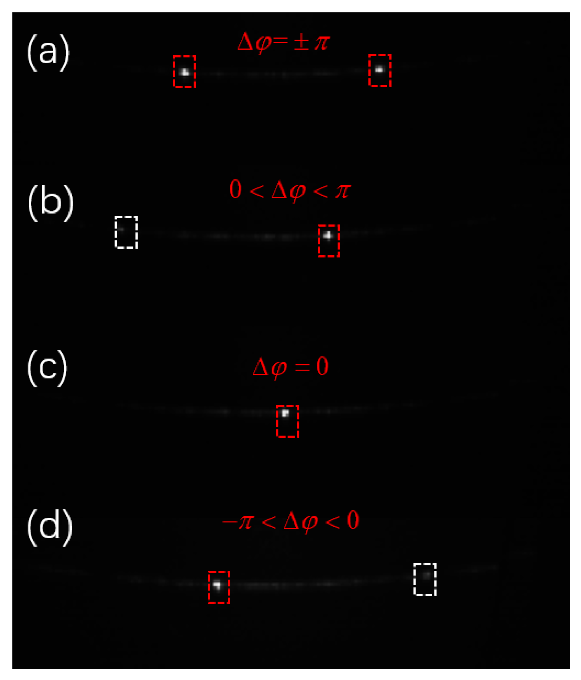
4. Experimental Results and Analysis
5. Conclusions
Author Contributions
Funding
Institutional Review Board Statement
Informed Consent Statement
Data Availability Statement
Conflicts of Interest
References
- Van Acoleyen, K.; Bogaerts, W.; Jágerská, J.; Le Thomas, N.; Houdré, R.; Baets, R. Off-chip beam steering with a one-dimensional optical phased array on silicon-on-insulator. Opt. Lett. 2009, 34, 1477–1479. [Google Scholar] [CrossRef] [PubMed]
- Hutchison, D.N.; Sun, J.; Doylend, J.K.; Kumar, R.; Heck, J.; Kim, W.; Phare, C.T.; Feshali, A.; Rong, H. High-resolution aliasing-free optical beam steering. Optica 2016, 3, 887–890. [Google Scholar] [CrossRef]
- Chung, S.; Abediasl, H.; Hashemi, H. A monolithically integrated large-scale optical phased array in silicon-on-insulator CMOS. IEEE J. Solid-State Circuits 2017, 53, 275–296. [Google Scholar] [CrossRef]
- Doylend, K.J.; Heck, M.J.R.; Bovington, J.T.; Peters, J.D.; Coldren, L.A.; Bowers, J.E. Two-Dimensional Free-Space Beam Steering with an Optical Phased Array on Silicon-on-Insulator. Opt. Express 2011, 19, 21595–21604. [Google Scholar] [CrossRef] [Green Version]
- Sun, J.; Timurdogan, E.; Yaacobi, A.; Hosseini, E.S.; Watts, M.R. Large-Scale Nanophotonic Phased Array. Nature 2013, 493, 195–199. [Google Scholar] [CrossRef]
- Zhang, L.; Wang, Y.; Hou, Y.; Song, J. Uniform Rectangular Distribution of Far-Field Intensity by Optical Phased Array. Opt. Commun. 2021, 509, 127661. [Google Scholar] [CrossRef]
- Li, Y.; Chen, B.; Na, Q.; Xie, Q.; Tao, M.; Zhang, L.; Zhi, Z.; Li, Y.; Liu, X.; Luo, X.; et al. Wide-Steering-Angle High-Resolution Optical Phased Array. Photonics Res. 2021, 9, 2511–2518. [Google Scholar] [CrossRef]
- Zhang, L.; Li, Y.; Hou, Y.; Wang, Y.; Tao, M.; Chen, B.; Na, Q.; Li, Y.; Zhi, Z.; Liu, X.; et al. Investigation and Demonstration of a High-Power Handling and Large-Range Steering Optical Phased Array Chip. Opt. Express 2021, 29, 29755–29765. [Google Scholar] [CrossRef]
- Chen, B.; Li, Y.; Zhang, L.; Li, Y.; Liu, X.; Tao, M.; Hou, Y.; Tang, H.; Zhi, Z.; Gao, F.; et al. Unidirectional Large-Scale Waveguide Grating with Uniform Radiation for Optical Phased Array. Opt. Express 2021, 29, 20995–21010. [Google Scholar] [CrossRef]
- Xu, W.; Zhou, L.; Lu, L.; Chen, J. Aliasing-Free Optical Phased Array Beam-Steering with a Plateau Envelope. Opt. Express 2019, 27, 3354–3368. [Google Scholar] [CrossRef]
- Wang, P.; Luo, G.; Li, Y.; Yang, W.; Yu, H.; Zhou, X.; Zhang, Y.; Pan, J. Large scanning range optical phased array with a compact and simple optical antenna. Microelectron. Eng. 2020, 224, 111237. [Google Scholar] [CrossRef]
- Wang, P.; Luo, G.; Xu, Y.; Li, Y.; Su, Y.; Ma, J.; Wang, R.; Yang, Z.; Zhou, X.; Zhang, Y.; et al. Design and fabrication of a SiN-Si dual-layer optical phased array chip. Photonics Res. 2020, 8, 912–919. [Google Scholar] [CrossRef]
- Ma, P.; Luo, G.; Wang, P.; Ma, J.; Wang, R.; Yang, Z.; Zhou, X.; Zhang, Y.; Pan, J. Unidirectional SiN antenna based on dual-layer gratings for LiDAR with optical phased array. Opt. Commun. 2021, 501, 127361. [Google Scholar] [CrossRef]
- Luo, G.; Wang, P.; Ma, J.; Wang, R.; Yang, Z.; Xu, Y.; Yu, H.; Zhou, X.; Zhang, Y.; Pan, J. Demonstration of 128-channel Optical Phased Array With Large Scanning Range. IEEE Photonics J. 2021, 13, 6800710. [Google Scholar] [CrossRef]
- Liu, Q.; Lu, Y.; Wu, B.; Jiang, P.; Cao, R.; Feng, J.; Guo, J.; Jin, L. Silicon Optical Phased Array Side Lobe Suppression Based on an Improved Genetic Algorithm. In Proceedings of the 2020 Asia Communications and Photonics Conference (ACP) and International Conference on Information Photonics and Optical Communications (IPOC), Beijing, China, 24–27 October 2020; pp. 1–3. [Google Scholar]
- Wang, X.C.Y.; Liu, C.; Zhao, X.; Chen, J.; Han, X.; Shi, Y. Phase Noise Compensation of Silicon-Based Optical Phased Array Chip. Acta Opt. Sin. 2021, 41, 2323001. [Google Scholar] [CrossRef]
- Zhang, W.; Li, L.; Chen, W. A chaotic stochastic parallel gradient descent algorithm for fast phase correction of optical phased array. In Proceedings of the Eleventh International Conference on Information Optics and Photonics (CIOP 2019), Xi’an, China, 6–9 August 2019. [Google Scholar]
- Vorontsov, M.A.; Carhart, G.W.; Ricklin, J.C. Adaptive phase-distortion correction based on parallel gradient-descent optimization. Opt. Lett. 1997, 22, 907–909. [Google Scholar] [CrossRef]
- Vorontsov, M.A. Decoupled stochastic parallel gradient descent optimization for adaptive optics: Integrated approach for wave-front sensor information fusion. JOSA A 2002, 19, 356–368. [Google Scholar] [CrossRef]
- Nesterov, Y. A method for unconstrained convex minimization problem with the rate of convergence o(1/k^2). Dokl. AN USSR 1983, 269, 543–547. [Google Scholar]
- Sutskever, I.; Martens, J.; Dahl, G.; Hinton, G. On the importance of initialization and momentum in deep learning. In Proceedings of the International Conference on Machine Learning, Atlanta, GA, USA, 16–21 June 2013; pp. 1139–1147. [Google Scholar]
- Alemany, R.; Muñoz, P.; Pastor, D.; Domínguez, C. Thermo-Optic Phase Tuners Analysis and Design for Process Modules on a Silicon Nitride Platform. Photonics 2021, 8, 496. [Google Scholar] [CrossRef]
- Harris, N.C.; Ma, Y.; Mower, J.; Baehr-Jones, T.; Englund, D.; Hochberg, M.; Galland, C. Efficient, compact and low loss thermo-optic phase shifter in silicon. Opt. Express 2014, 22, 10487–10493. [Google Scholar] [CrossRef] [Green Version]
- Jacques, M.; Samani, A.; El-Fiky, E.; Patel, D.; Xing, Z.; Plant, D.V. Optimization of thermo-optic phase-shifter design and mitigation of thermal crosstalk on the SOI platform. Opt. Express 2019, 27, 10456–10471. [Google Scholar] [CrossRef] [PubMed]
- Poulton, C.V.; Russo, P.; Timurdogan, E.; Whitson, M.; Byrd, M.J.; Hosseini, E.; Moss, B.; Su, Z.; Vermeulen, D.; Watts, M.R. High-performance integrated optical phased arrays for chip-scale beam steering and lidar. In Proceedings of the CLEO: Applications and Technology, San Jose, CA, USA, 13–18 May 2018; p. ATu3R.2. [Google Scholar]
- Rahim, A.; Hermans, A.; Wohlfeil, B.; Petousi, D.; Kuyken, B.; Van Thourhout, D.; Baets, R. Taking silicon photonics modulators to a higher performance level: State-of-the-art and a review of new technologies. Adv. Photonics 2021, 3, 024003. [Google Scholar] [CrossRef]
- Shi, P.; Lu, L.; Liu, C.; Zhou, G.; Xu, W.; Chen, J.; Zhou, L. Optical FMCW Signal Generation Using a Silicon Dual-Parallel Mach-Zehnder Modulator. IEEE Photonics Technol. Lett. 2021, 33, 301–304. [Google Scholar] [CrossRef]
- Song, J.; Fang, Q.; Tao, S.H.; Liow, T.Y.; Yu, M.B.; Lo, G.Q.; Kwong, D.L. Fast and low power Michelson interferometer thermo-optical switch on SOI. Opt. Express 2008, 16, 15304–15311. [Google Scholar] [CrossRef]
- Xia, P.; Yu, H.; Zhang, Q.; Fu, Z.; Wang, X.; Wang, Y.; Jiang, X.; Yang, J. A Silicon Optical Single Sideband Modulator With Ultra-High Sideband Suppression Ratio. IEEE Photonics Technol. Lett. 2020, 32, 963–966. [Google Scholar] [CrossRef]
- Zhang, Z.; Huang, Q.; Zhou, Z.; Wang, Y.; Yu, H.; Yang, J. Silicon Optical Phased Array Based on Carrier-depletion Phase Shifters. In Proceedings of the 2021 Asia Communications and Photonics Conference (ACP), Shanghai, China, 24–27 October 2021; pp. 1–2. [Google Scholar]
- Krochin-Yepez, P.-A.; Scholz, U.; Zimmermann, A. CMOS-Compatible Measures for Thermal Management of Phase-Sensitive Silicon Photonic Systems. Photonics 2020, 7, 6. [Google Scholar] [CrossRef] [Green Version]
- Yepez, P.A.K.; Scholz, U.; Caspers, J.N.; Zimmermann, A. Novel Measures for Thermal Management of Silicon Photonic Optical Phased Arrays. IEEE Photonics J. 2019, 11, 6602415. [Google Scholar] [CrossRef]
- Yepez, P.A.K.; Scholz, U.; Zimmermann, A. Temperature Dependence of the Steering Angles of a Silicon Photonic Optical Phased Array. IEEE Photonics J. 2020, 12, 6800813. [Google Scholar] [CrossRef]


Publisher’s Note: MDPI stays neutral with regard to jurisdictional claims in published maps and institutional affiliations. |
© 2022 by the authors. Licensee MDPI, Basel, Switzerland. This article is an open access article distributed under the terms and conditions of the Creative Commons Attribution (CC BY) license (https://creativecommons.org/licenses/by/4.0/).
Share and Cite
Wang, Z.; Yang, Y.; Wang, R.; Luo, G.; Wang, P.; Su, Y.; Pan, J.; Zhang, Y. Improved SPGD Algorithm for Optical Phased Array Phase Calibration. Appl. Sci. 2022, 12, 7879. https://doi.org/10.3390/app12157879
Wang Z, Yang Y, Wang R, Luo G, Wang P, Su Y, Pan J, Zhang Y. Improved SPGD Algorithm for Optical Phased Array Phase Calibration. Applied Sciences. 2022; 12(15):7879. https://doi.org/10.3390/app12157879
Chicago/Turabian StyleWang, Zheng, Yibo Yang, Ruiting Wang, Guangzhen Luo, Pengfei Wang, Yanmei Su, Jiaoqing Pan, and Yejin Zhang. 2022. "Improved SPGD Algorithm for Optical Phased Array Phase Calibration" Applied Sciences 12, no. 15: 7879. https://doi.org/10.3390/app12157879