Article

Dynamic and Wrench-Feasible Workspace Analysis of a Cable-Driven Parallel Robot Considering a Nonlinear Cable Tension Model

1
Department of Mechanical Engineering, National Kaohsiung University of Science and Technology, Kaohsiung 80778, Taiwan
2
Faculty of Engineering and Technology, Nguyen Tat Thanh University, 300a Nguyen Tat Thanh, Ward 13, District 4, Ho Chi Minh City 700000, Vietnam
*
Author to whom correspondence should be addressed.
Appl. Sci. 2022, 12(1), 244; https://doi.org/10.3390/app12010244
Submission received: 27 November 2021 / Revised: 22 December 2021 / Accepted: 23 December 2021 / Published: 27 December 2021
(This article belongs to the Special Issue Selected Papers from iTIKI IEEE ICASI 2021)

Abstract

:
Cable-driven parallel robots (CDPRs) have several advantages and have been widely used in many industrial fields, especially industrial applications that require high dynamics, high payload capacity, and a large workspace. In this study, a design model for a CDPR system was proposed, and kinematic and dynamic modeling of the system was performed. Experiments were carried out to identify the dynamic modulus of elastic cables based on the dynamic mechanical analysis (DMA) method. A modified kinematic equation considering cable nonlinear tension was developed to determine the optimal cable tension at each position of the end-effector, and the wrench-feasible workspace was analyzed at various motion accelerations. The simulation results show that the proposed CDPR system obtains a large workspace, and the overall workspace is satisfactory and unrestricted for moving ranges in directions limited by the X-axis and the Y-axis from −0.3 to 0.3 m and by the Z-axis from 0.1 to 0.7 m. The overall workspace was found to depend on the condition of acceleration as well as the moving ranges limited by the end-effector. With an increase in external acceleration, the cable tension distribution increased and reached a maximum in the case of 100 m/s2.

1. Introduction

Cable-driven parallel robots (CDPRs) use flexible cables to control an end effector by winding and unwinding cables instead of using the rigid links of common parallel robots. The use of light cables with high load-withstanding ability as actuators can reduce the actuator weight as well as the inertia; thus, CDPRs have many typical advantages, such as high dynamics, low inertia, and large workspaces. Due to these advantages, CDPRs have been widely used in various fields, such as in radio telescopes [1], multiple mobile cranes [2], waist rehabilitation [3], and construction cable robots [4]. The CDPR system has also been studied by researchers from different perspectives. The control algorithm is an important factor affecting the accuracy and stability of the robot system. To ensure the stability of the end-effector during movement, the use of a hybrid position-force control algorithm as an asynchronous control of the cable force was proposed [5]. A passivity-based control for a planar cable-driven manipulator system was also investigated. In this work, to simplify the modeling process of the system, a lumped-mass model is used, and each cable is modeled individually. Then, the derivation of Lagrange’s equation and the null-space method is used to derive the dynamics of the system [6]. To dynamically control CDPRs in [7], visual feedback with linearizing inner loop control was proposed, and this new approach allows for the control of CDPRs when using long cables or polymer cables. In addition, the stability of the dynamic control scheme was demonstrated using Tikhonov’s theorem. Characteristics of the cable used for CDPR that are related to the accuracy of the end-effector were also considered based on nonlinear viscoelastic properties, such as structural elongation and hysteresis. Therefore, to improve the accuracy, many studies have considered these attributes. Rather than the commonly used elastic cable approach, an approach based on the numerical analysis of cable elements was proposed in [8], where a novel formulation for three-dimensional cables was developed. Besides that, the thermal-elastic of the proposed element was also analyzed. The proposed formulation leads to an explicit stiffness matrix this makes the new element more efficient in terms of the analysis time, and the research results in the literature indicate the advantages of the proposed scheme. Moreover, a simple model for cable elongation was incorporated to increase position accuracy for CDPR [9]. A hysteresis model was developed based on the Bouc–Wen model, and dynamic behavior, such as static creep, hardening effects, long-term recovery, and hysteresis, was described based on a viscoelastic model with only an integrated dynamic model [10,11,12]. However, to evaluate its performance, the workspace analysis of a CDPR, considering the condition of various accelerations, is an important issue.
The workspace of CDPR can be divided into two categories: dynamic and static [13]. The static workspace can be further divided into a wrench-closure workspace. Most of the research on CDPR has only considered a static condition in the analysis of the workspace. A workspace analysis under equilibrium conditions to evaluate external force was presented in [14]. Besides, a force-closure workspace analysis of CDPR was conducted based on a workspace with fully restrained positioning mechanisms. Because of the maintenance of positive cable tension, the general algorithm to generate a force-closure workspace was studied at various orientations of the end-effector [15]. Moreover, a method that is seen as one of the most efficient interior-point methods was improved in [16] to analyze the wrench-feasible workspace for general CDPR. This method uses the linear matrix inequalities and the projective method to obtain the wrench-feasible workspace. In [17], to analyze the wrench-feasible printing workspace, a methodology that considers the impact of cable mass and end-effector orientation was proposed. To ignore the inertia effects of the cable, this proposed method assumes that the motion of the end effector is slow. The cable profile is also considered for the checking of collisions based on kinetostatic analyses of the cable robot. In addition, the limitations of planar cable-driven parallel robots can be improved so that they cause a zero force on the borders of such a static wrench. Two different CDPRs, with and without a counterbalancing mechanism, were proposed for study and comparison, and then the improving effects of the proposed mechanism on the static wrench (SW) and available wrench set (AW) were demonstrated [18]. Similarly, two different CDPRs were used to analyze the workspace in [19], and a novel workspace from the control was proposed, namely the Control Stability Workspace (CSW). This workspace can determine whether the controller will be able to guide the platform of the CDPR to the desired position. Moreover, to determine the wrench-feasible workspace (WFW) for CDPR when subjected to external force and high payload and improve the optimum designs of CDPR, the overall workspace was maximized. Based on the kinematic equilibrium, the wrench-feasible workspace and twist feasible workspace were obtained and presented based on these case studies [20]. Despite much research already being conducted on the workspace analysis of general CDPR, a workspace analysis on musculoskeletal systems as cable-driven robots was proposed for the first time in [21]; the research results show that the proposed approach can produce a realistic workspace.
Recently, several studies on CDPRs focused on workspace analysis, but most of this research only considered static equilibrium conditions or gravity to determine the workspace. In their study, Heo et al. presented a wrench-feasible workspace [22]. Their study not only considered dynamic conditions based on the effect of various accelerations but also took into account the pulley-bearing friction factor. However, this factor analysis is only suitable for CDPR systems where the design of the drive uses multiple pulleys in series and is not applicable to other designs that only use a single pulley at anchor points of CDPR systems. As previously mentioned, cable tension is quite important. In a real CDPR system, the predicted cable tensions cannot easily improve the features of the robot due to the nonlinear characteristics of the cable as well as the nonlinear tension that occurs during motion. These characteristics affect the dynamic stability of CDPRs. In addition, the high acceleration generated on the wrench-feasible workspace affected the CDPR system significantly. Therefore, the workspace analysis of a CDPR with consideration of the nonlinear cable tension is an important issue in evaluating its performance. In this study, we focused on the nonlinear cable tension effect because tension varies when cables are actuated in dynamic conditions. Cable nonlinear tension modeling cannot be neglected in situations where high tension is imposed under varying acceleration. The methodologies to determine the feasible workspace of CDPR have been presented in many studies. However, for CDPR using polymer cables, the linear tension model can be used to determine the cable tension, but this model cannot be used to determine the feasible workspace of the CDPR system because it does not satisfy the nonlinear elastic properties of the polymer cable. In addition, the operation of the robot is also affected by dynamic phenomena associated with high cable length variations. The main contributions of this paper can be summarized as follows:
  • The dynamics of the redundant cable-driven parallel robot (CDPR) and the influence of pulley kinematics are presented.
  • A methodology for determining the wrench-feasible workspace (WFW) of a cable-driven parallel robot (CDPR) is proposed based on a nonlinear cable tension model.
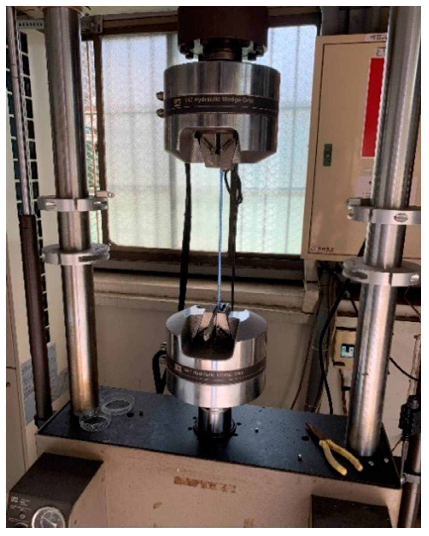
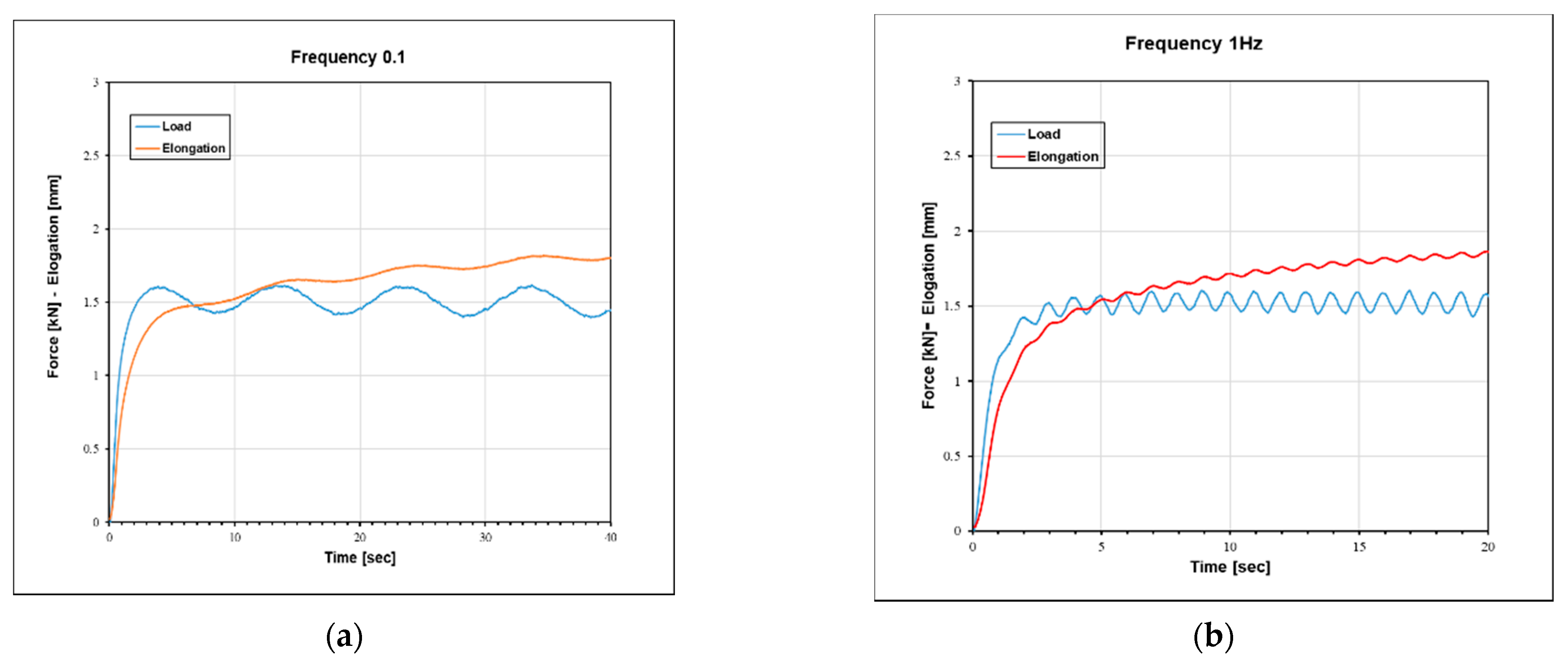
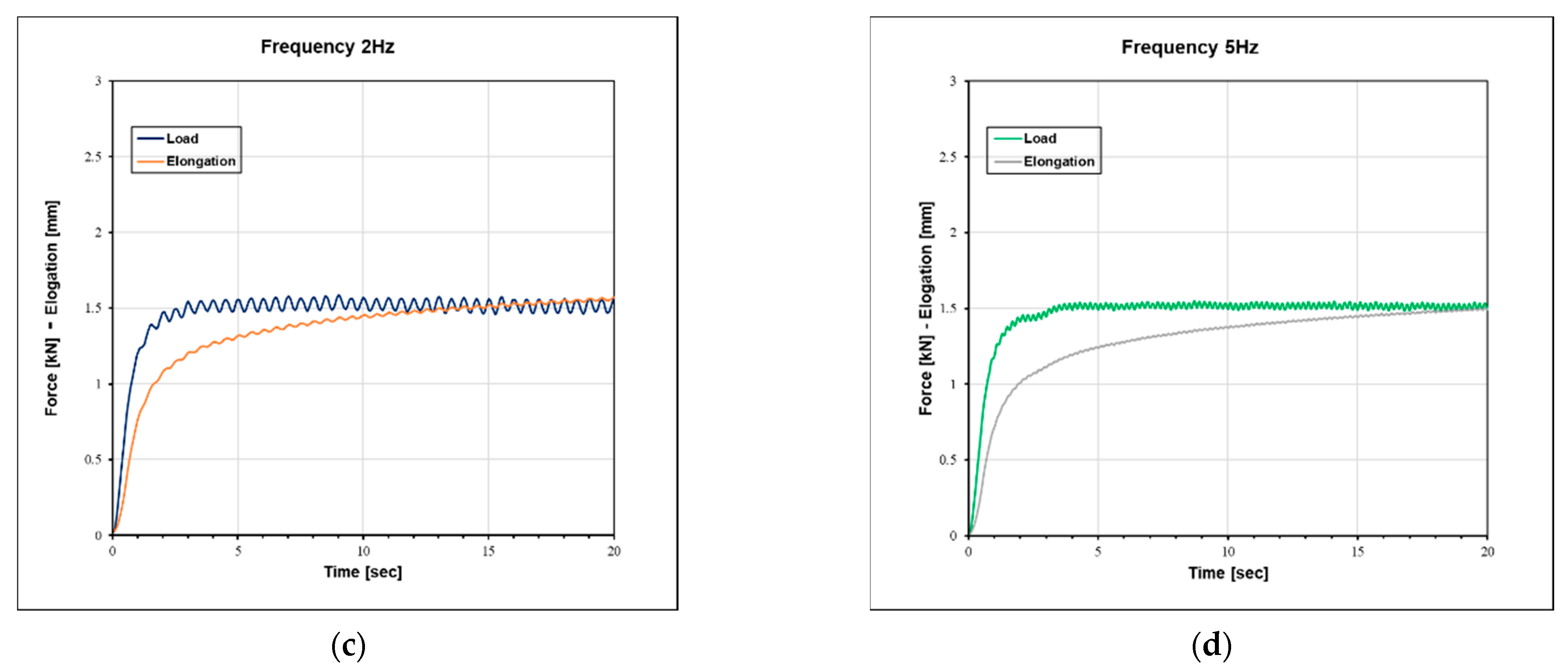
  • The dynamic elastic modulus of the polymer cable for the nonlinear tension model is obtained based on the dynamic mechanical analysis (DMA) method by changing the frequencies of the applied force on the cable and is presented for the first time in this article.
  • An approach to obtaining the redundant tensions and ensuring that the cable tensions are positive, using a nonlinear constraint for optimal function, is proposed.
The structure of the article is organized as follows. First, the kinematics equation and dynamics of CDPRs were derived. Next, a nonlinear tension formulation of cables was constructed, and experiments were carried out at different frequencies based on the dynamic mechanical analysis (DMA) method, from which the dynamic modulus of elasticity coefficients was determined. Third, cable nonlinear tensions were considered. Subsequently, optimization was conducted considering these nonlinear tensions, and a wrench-feasible workspace analysis was also conducted. Then, the simulation results are discussed, with the main contributions presented in the Conclusions section.

2. Modeling of the CDPR System

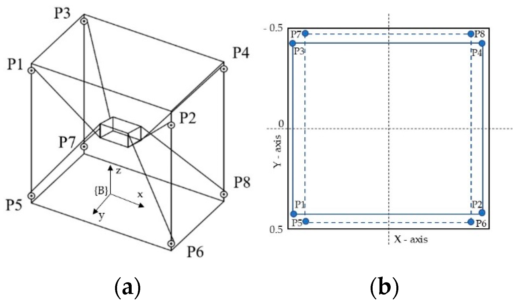
The configuration of the designed CDPR is shown in Figure 1. The cube frame dimension of the CDPR was 1 m × 1 m × 1 m (L × W × H). The pulleys were located asymmetrically to prevent intersections with each other during operation (Figure 1b). As shown in Figure 1b, four pulleys (P1, P2, P3, and P4) were upper pulleys. In contrast, four pulleys (P5, P6, P7, and P8) were lower pulleys. Additionally, the coordinates of the pulley location are listed in Table 1.
A flexible cable with high-strength Dynamica rope was used in this study. These cables started from the winches and then passed through the pulleys to the end-effector and were divided into four upper cables and lower cables. The position of the end-effector was controlled by these cables. In Figure 1a, it can be seen that, to reduce the moment caused by the end-effector during movement, the upper cables were connected to the bottom anchor points of the end-effector, and in contrast, the bottom cables were connected to the upper anchor points of the end-effector as described earlier [14]. Here, we used an end-effector size of 0.26 m × 0.26 m × 0.26 m, with a mass of 1 kg.

2.1. Kinematics of the Redundant-Actuated CDPR System

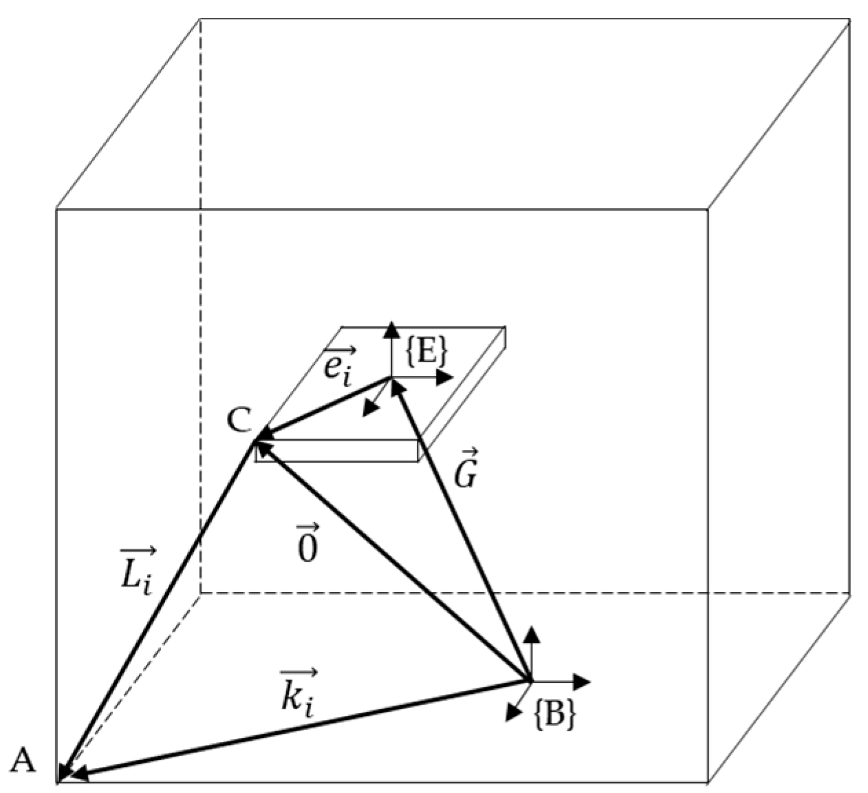
Briefly reviewing the kinematic model, the geometry of the CDPR robot is described by its proximal anchor points on the robot frame and the distal anchor points on the end-effector, which were defined by the vector. Figure 2 shows that B was the origin of the global coordinate, and the vector k i was described from the frame B to anchor point A of the frame. The vector denoted as G represented the vector from B to the center of the end-effector fixed frame E, the vector e i was connected from the end-effector fixed frame E to the anchor point C of the end-effector, and it described the position vector of the anchor point from E. In addition, the vector of cable length denoted as L i was derived from the given vector. The cable length of the cables could be obtained by solving the inverse position kinematics (IPK). By applying a vector loop, the cable vector L i was established as follows:
L i = k i ( G + e i )
where the index i denotes the cable number.
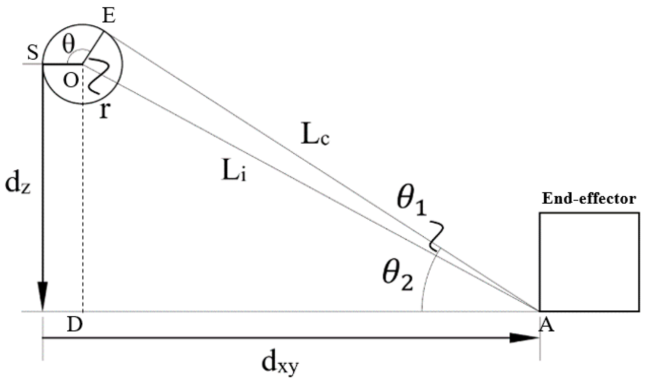
In a typical CDPR robot system, the pulleys have an important role, and they are used to guide the cable at point A towards the end-effector; the proximal anchor points of the robots are simplified to be ideal points. Thus, the starting point of the cable described by the position vector is not a constant but depends on the current pose of the robot and the wrapping angle of the cable around the pulley is a variable. Moreover, in a CDPR system, the real cables achieve a reasonable lifetime only when a minimum bending radius is exceeded [23]. Thus, determining the starting point of the cable is essential to improve the accuracy of its position and the effect of pulley kinematics in this system. A model of the pulley kinematics is presented in Figure 3, and the kinematic equation is given as follows:
L c o m p = L c + r θ
where Lcomp is a cable length compensation, Lc is the free cable length from point A to point B, r is the pulley radius and θ is the wrapping angle of the cable. For the two right-angled triangles ADO and AOE shown in Figure 3, OA is the common side. Therefore, based on the Pythagorean theorem for the two right-angled triangles, the following can be obtained:
( d x y r ) 2 + d z 2 = L i 2 = L c 2 + r 2
Considering the tetragon EODA, there are two angles that are right-angles. Thus, the enclosed angle θ1 + θ2 at point A equals the sought complementary angle θ at point O [5,23,24]. Using the elementary trigonometric function, the cable wrapping angle around the pulley is given by Equation (4).
θ = θ 1 + θ 2 = arccos L c ( d x y r ) 2 + d z 2 + arccos d z ( d x y r ) 2 + d z 2
where d x y = d x 2 + d y 2 . Given the coordinates of the point at pulley O whose coordinates are O(x2, y2, x2), at the anchor point of end-effector A(x1, y1, z1), and at the center of end-effector G(x0, y0, z0), then the values dx, dy, and dz are coordinates in the x, y, z directions, which are calculated by the equation: L(x, y, z) = O − A − G. dz represents coordinates of point E with respect to the frame point B coordinates. Finally, the equation for determining the corrected cable length, which takes into account pulley kinematics to solve the inverse kinematics, can be transformed as follows:
L = L c + r θ

2.2. Dynamic Modeling for the CDPR System

To derive the dynamics equation for the CDPR system, first, a static equilibrium model for the system should be established by applying the forces and moments to the end-effector, which consists of internal forces and external forces. These forces and moments are from different parts, with one part from the eight cables and the other from the environment. Considering the static equilibrium, the total forces and moments exerted on the end effector should be zero, and the equilibrium equations can be obtained as follows:
i = 1 8 T i + m g = F r
i = 1 8 ( e i × T i ) = M r
where Ti denotes the tension vector for the ith cable, m is the mass of the end-effector, g is the gravitational acceleration, and Fr and Mr indicate the resultant forces and moment vector, respectively. For convenience, we assumed that the origin geometrical center was located at the center of gravity. Therefore, the moment caused by gravity could be ignored. Combining Fr and Mr together, we obtained the wrench vector:
W R = { F r M r } T
From Equations (6)–(8), the static equilibrium equation can be described as follows:
[ J ] T T + { m g 0 } = W R
J T = [ L 1 ^ L 2 ^ L 8 ^ e 1 ^ × L 1 ^ e 2 ^ × L 2 ^ e 8 ^ × L 8 ^ ]
where J represents the cable tension Jacobian matrix, [J]T represents the transposed matrix of J, and e i ^ and L i ^ denote the unit cable length vector. T is the vector of cable tensions:
T = { t 1 t 2 t 8 } T
To consider the effects of external force caused by the acceleration of the end-effector, the dynamics equation was derived as shown in Equation (12).
[ J ] T T + { F e M e } = [ m 0 0 I ] X ¨ + [ 0 ω + I × ω ]
where Fe and Me denote the external force and moment, respectively; matrices m and I are a [3 × 3] diagonal matrix of the end-effector mass and tensor of inertia, respectively; X ¨ is the acceleration of the end-effector; and ω denotes the angular velocity vector. These are defined as follows:
X ¨ = { x ¨ y ¨ z ¨ ω ˙ x ω ˙ y ω ˙ z } T
ω = { ω x ω y ω z }
In this work, the CDPR system was based on translation-only motion with a nearly constant orientation. Thus, the angular velocity ω was small enough and the last term, including the angular velocity on the right side of Equation (13), was negligible in this research.

3. Nonlinear Tension Model of the DYNAMICA Cable

3.1. Nonlinear Cable Tension Formulation

This section aims to establish the nonlinear tension formulation, and the dynamic modeling presented in the previous section will be based on this model to analyze the feasible workspace of the CDPR system. The linear tension formulations are described simply as a linear spring, and they are commonly used in CDPR systems. These formulations cannot satisfy the nonlinear characteristics of the elastic cable and the effect of dynamic phenomena with high cable length variations. Therefore, a nonlinear tension model is considered in this study. To provide a total nonlinear tension formulation that is suitable for highly dynamic applications, nonlinear tension is proposed as follows.
According to [25], applying the Hooke’s law definition, the stress–strain relationship can be expressed as:
σ ( t ) = E ε ( t )
where ε ( t ) = Δ l ( t ) l ( t ) , l is the cable length, σ represents the stress, and E and ɛ are the modulus of elasticity and strain, respectively. Assuming that cross-sectional area A is a constant, then the cable tension can be written as follows:
T ( t ) = A σ ( t )
where σ ( t ) = T ( t ) A , T is the cable tension. Equation (16) can be rewritten as the equation shown below by the time derivative of the cable tension:
T ˙ ( t ) = E A ε ˙ ( t )
Finally, the nonlinear cable tension equation is obtained by integrating Equation (18):
T ( t ) = E A ln ( l ( t ) l 0 ) + T 0
where l(t) denotes the cable length, l0 is the initial length of the cable, and T0 is the initial cable tension. This equation is valid for highly dynamic systems, such as CDPR systems.
For the CDPR system using cables as polymer materials, the nonlinear elastic properties of the cable or viscosity are generated by the dynamic phenomenon with high cable length variation. The linear tension model can be used to determine the cable tension. However, it is not suitable for determining the feasible workspace of the CDPR system because it does not satisfy the nonlinear elastic properties of the polymer cable. Moreover, the operation of the robot is also affected by dynamic phenomena associated with high cable length variations. Therefore, kinematics and dynamics Equation (12) can be extended by considering Equation (18). Hence, the modified equation that includes the non-linear tension is given as:
[ J ] T ( T + E A ln ( L ( t ) L 0 ) + T 0 ) + { m g 0 } = W R
where [J]Trepresents the transposed matrix of J. To find solutions for the cable tensions, by inverting Equation (19) then multiplying by the pseudoinverse matrix of J and adding the term of the homogeneous solution [11], the equation of tension can be determined according to the equation below.
T + E S ln ( L ( t ) L 0 ) + T 0 = [ J ] P ( W R { m g 0 } ) + ( [ I 8 ] [ J ] P [ J ] ) { z }
where [J]P represents the Moore–Penrose pseudoinverse Jacobian matrix and [I8] is the [8 × 8] identity matrix. Equation (20) combines two parts, with the term on the right-hand side representing a particular solution and the second term representing the homogeneous solution. Unlike rigid arm mechanisms, the CDPR robot uses flexible cables to hold the end-effector. Therefore, the vector {z} is an arbitrary vector and was chosen to ensure that all cable tensions were positive. To maintain the positive cable tension and resolve the problem of actuation redundancy in the CDPR workspace, many methods have been proposed, such as the closed-form force distribution method [26] and an improved force distribution algorithm [27]. In this study, the nonlinear constraint of the optimal method was used and the cable tension was obtained by using the objective function, as shown in Equations (21)–(23).
(21) Minimize   function   s ( f ) = i = 1 8 T i 2 (22) Subject   to   T min T i T max (23) Nonlinear   constraint ( [ I 8 ] [ J ] Θ [ J ] ) { z } [ J ] Θ W R T min
The flowchart of the proposed method, as shown in Figure 4, indicates the details of the iterative method used to find the optimal tension values of the wrench-feasible workspace. In this flowchart, it can be seen that, for a given trajectory of the end-effector, from the inverse kinematic equation, the Jacobian matrix of J, and external force WR were calculated, respectively. Then, the Moore–Penrose pseudoinverse Jacobian matrix [J]P was calculated and the vector {z} represents an arbitrary vector that was chosen to ensure that all cable tensions were positive. In this step, the nonlinear constraint of the optimal method was used, as shown in Equations (21)–(23). Finally, the cable tension was obtained.

3.2. Dynamic Modulus of Elasticity

The modulus of elasticity obtained by the quasi-static method is frequently used to describe the dynamic behavior of CDPR systems. However, the effectiveness of this method is negligible; thus, many researchers have proposed different methods. For example, in [28], a cable model integrating hysteresis effects by applying force was improved; and in [10], a complex model combining a linear damper model and a rate-independent hysteresis model was proposed. In this article, to identify the dynamic modulus under forced oscillation, the dynamic mechanical analysis (DMA) method was used. The DMA method can be simply described as the application of a sinusoidal force to the cable to cause a sinusoidal elongation response [29]. In addition, an advantage of the DMA method is that it is possible to identify a dynamic modulus under various frequencies.
To obtain the modulus of elasticity, we conducted experiments. First, the experimental setup included the tensile test using an MTS-810 Material Testing System (Figure 5). A Dynamica cable with polyethylene material was used in the CDPR system. The cable of 6 mm diameter consisted of 12 strands, with a breaking strength at t of 4.20. Then, four samples of the Dynamica cable with a length of 300 mm were prepared and fixed on an MTS-810 material testing system, and four tests were performed at different frequencies of 0.1, 1, 2, and 5 Hz, respectively. A preload was applied to the cable at 1500 N before sinusoidal tensile loading was controlled at different frequencies, each experiment was repeated 3 times and averaged, and the results were then analyzed. By verifying the amplitude of the elongation at the peak of a sine wave and the phase lag between the applied force and the elongation sine waves, the dynamic modulus and the damping could be calculated. Based on the discussion above, it is known that the DMA allows for the calculation of a dynamic modulus from the cable response. E′ is a real part of the dynamic modulus described as a recovered part and can be considered as the elastic modulus. Compared with the Young’s modulus, which is normally calculated based on the resulting stresses and strains and represented as the slope of a line, E′ can be a point on the line [29]. In addition, in this study, the tests differed, with the material stretched in the stress–strain test but oscillating in the dynamic test. E′ is defined as follows:
E = σ max ε max cos φ
where σmax and εmax are the maximum amplitude of the applied stress and the maximum amplitude of the strain response, respectively. The ratio of the maximum amplitude stress–strain is denoted as E* and called the absolute value of the dynamic modulus, and φ is the phase angle. E represents the energy dissipation, also called the imaginary modulus. It is calculated as follows:
E = σ max ε max sin φ
The ratio of the dissipation to the storage modulus is called the damping η and defined as follows:
η = E E = tan φ
Figure 6 shows the resulting sinusoidal elongation when a sinusoidal force at various frequencies was applied. The pre-force exerted on the cable was 1.5 kN before controlling the sinusoidal force waves and the values of the elongation varied depending on the frequencies. The values of the elongation varied depending on the frequencies. The higher the frequency, the smaller the rate of change in the elongation value. In addition, the elongation profile was a time-dependent nonlinear curve. Although the sinusoidal oscillation was constant, the cable elongation increased significantly over time. Table 2 shows the dynamic and elastic modulus, the phase angle, and the damping factor. At a very low frequency of 0.1 Hz, the dynamic modulus decreased significantly from 92.6 to 75.5 GPa, and it was almost constant at 1 Hz and 2 Hz; then, the value increased insignificantly at a high frequency because of the nonlinear characteristics of the Dynamica cable, including the effect of cable hardness and dynamic creep. Additionally, the absolute values of the dynamic modulus and damping factor tended to decrease gradually with increasing frequency.

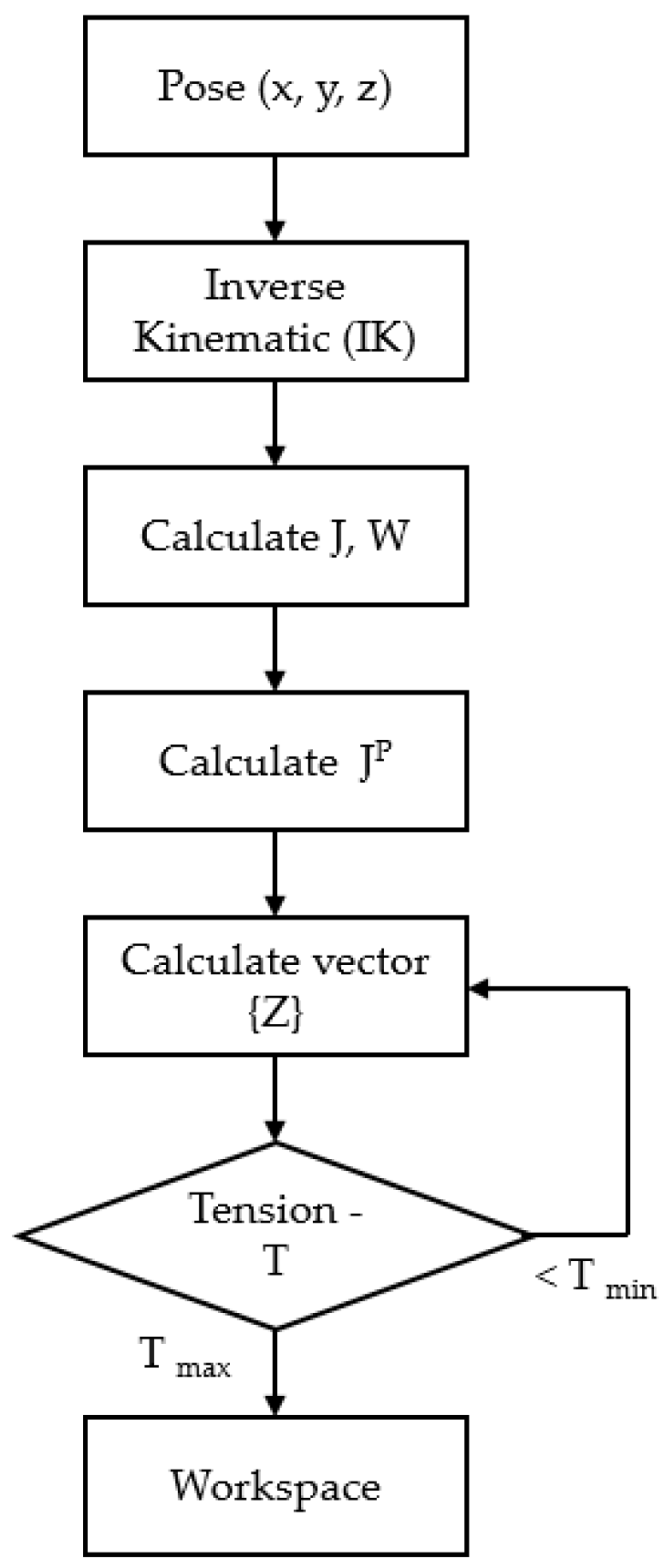
4. Workspace Analysis

In this article, simulations were performed for the proposed CDPR system considering nonlinear cable tension. The wrench-feasible workspace (WFW) was analyzed for a given motion trajectory of the end-effector and to solve Equation (20). The wrench-feasible workspace of a CDPR is defined as the set of positions for which a given set of wrenches, called the required net wrench set, can be balanced by the set of all wrenches, which the CDPR cables can generate in a determined position of the workspace [18,30,31]. To determine the wrench-feasible workspace, simulations were carried out for the end-effector moves in the range of X, Y, and Z directions. The moving ranges were limited in direction by the X-axis and the Y-axis from −0.3 to 0.3 m and limited in the Z-axis from 0.1 to 0.7 m. Additionally, the simulations were implemented at various accelerations at 10 and 100 m/s
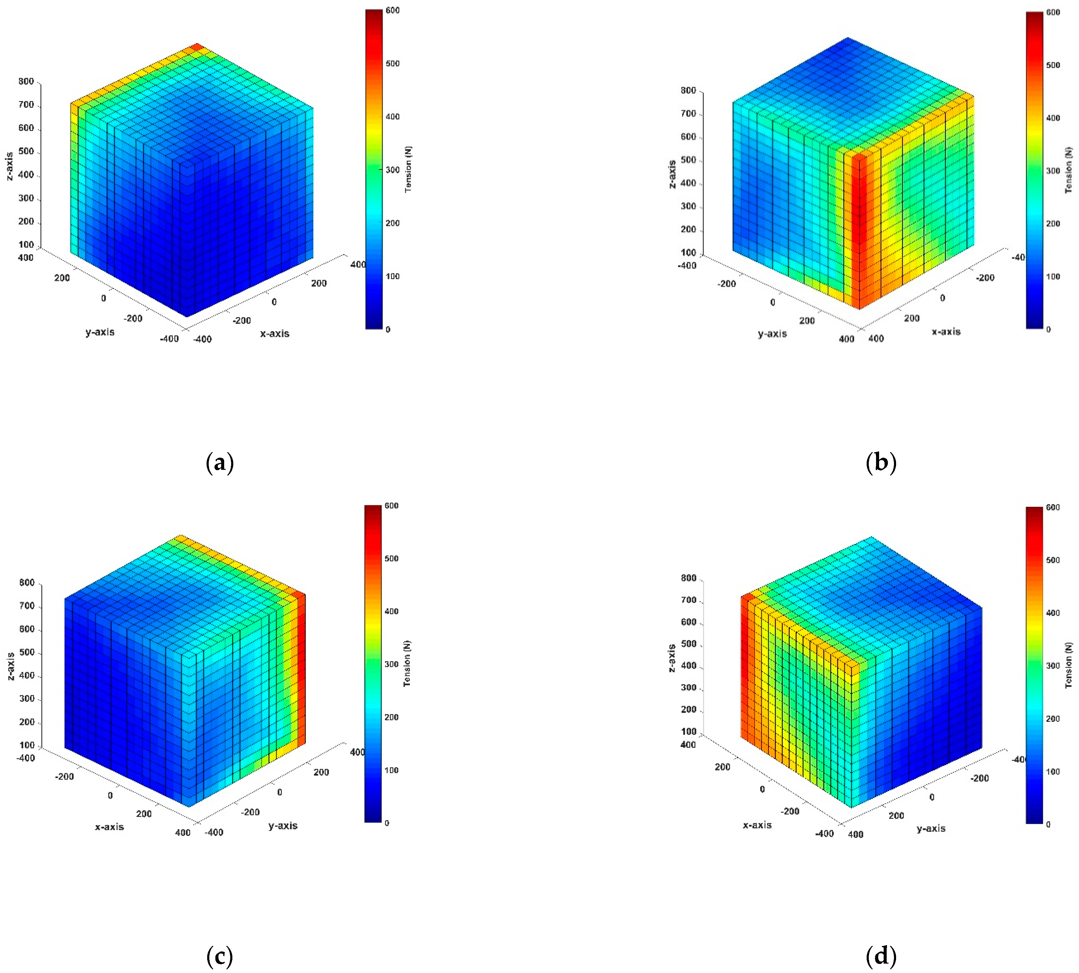
2, and a geometric model was built by MATLAB simulation. The weight of the end-effector is 10 N and the maximum loading limit of the cable is 4000 N for a Dynamica cable with a diameter of 6 mm (breaking strength certificate). The step size for the MATLAB WFW simulation is 100 mm. According to the definition of feasible workspace, all of the cable tension at each position needed to be constrained to maintain positive tension and not exceed the maximum loading of the cable. Besides, each box was denoted with a color in the diagram; each color represented the maximum cable tension value at each acting position. Moreover, when the calculated cable tension values exceeded the limited value, the end-effector at these positions was eliminated from the workspace domain and appeared vacant in the figures.
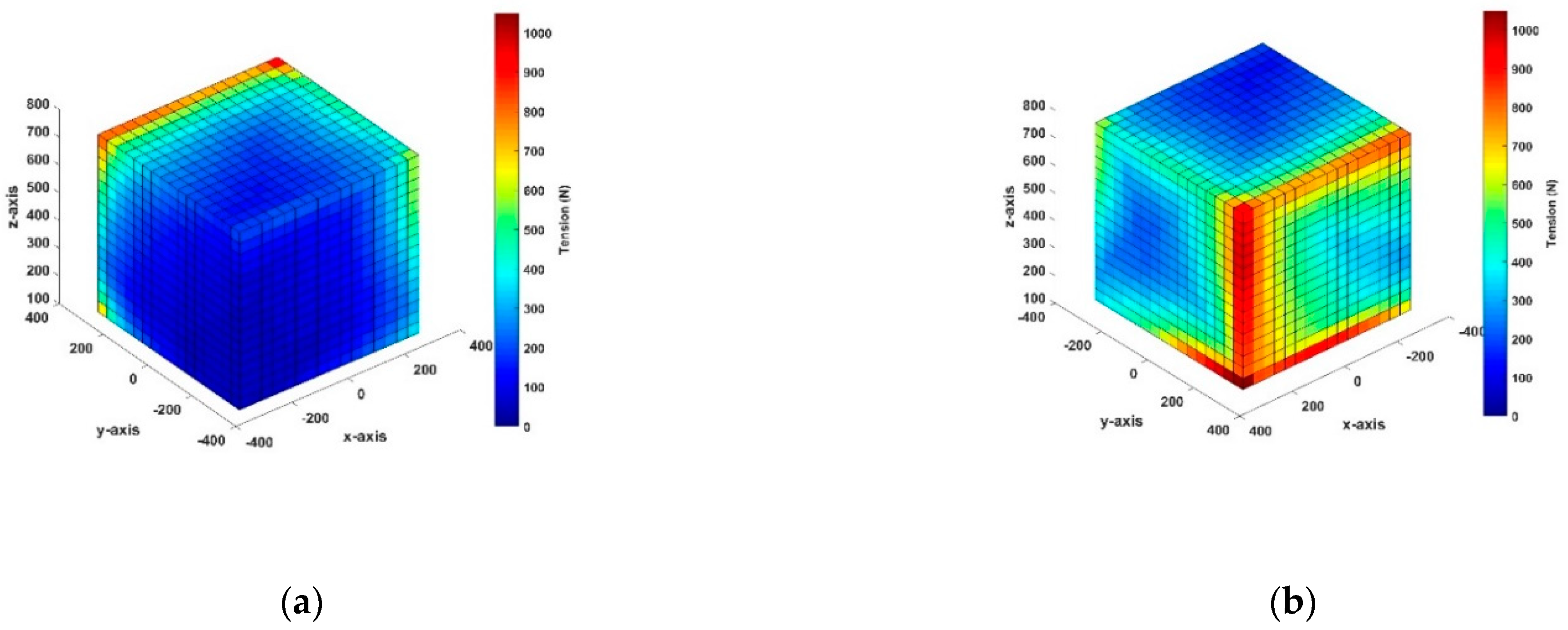
The simulation results of the wrench-feasible workspace considering nonlinear tension are shown in Figure 7 and Figure 8. In the case of the end-effector moves in the X, Y, and Z directions, the figures show the maximum cable tension distribution of the eight cables when applying various accelerations for a given position motion of the end-effector. As shown in these figures, the average cable tension was ∼100 N at an acceleration of 10 m/s2 and ~200 N at an acceleration of 100 m/s2. Moreover, the total maximum tensions increased significantly from 600 N to 1000 N when the acceleration varied from 10 m/s2 to 100 m/s2. In addition, maximum tension values appeared at the vertices and edges of the workspace. The negative cable tension disappeared in the moving direction due to the constraint of the optimal method. Considering the case of X-direction acceleration (Figure 7a,b, and Figure 8a,b), the same directions between the front view and back view surface were compared, and the tension distribution of the back view surface was slightly higher than that in the opposite surface. The tension region had a C shape, with the edges created by the contiguous faces, and the surrounding area had a higher tension distribution than that of the front view surface. This tension distribution was similar for both cases of X-direction acceleration. In particular, the vertical edge was the edge created between the back view surface of the X-direction and the front view surface of the Y-direction, which had the highest tension distribution in this position because of the optimal method and the variable cable length; thus, the cable was expected to maintain a positive tension for the acceleration in the X-direction—the greater the acceleration, the greater the tension distribution in this region. This finding means that the CDPR system is restricted from working in this area and the tension must be decreased so that the wrench-feasible workspace can be improved.
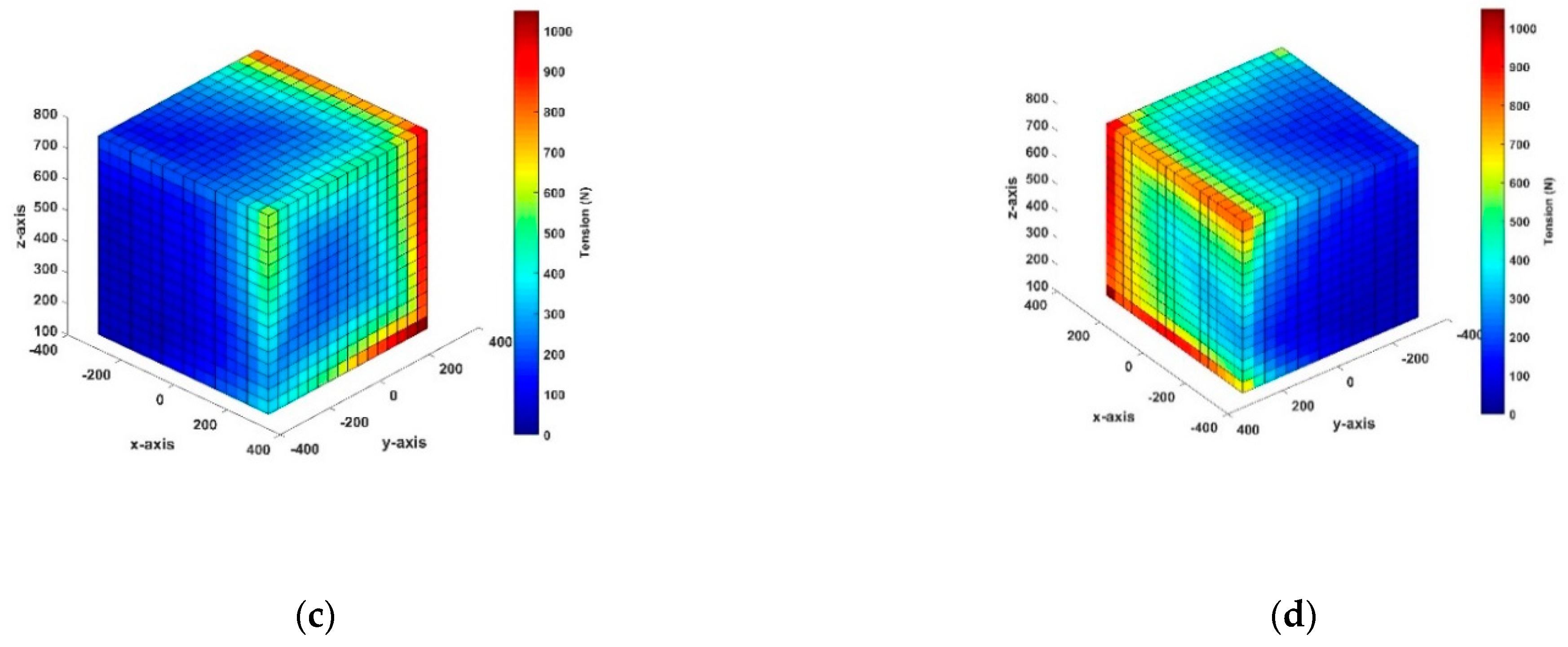
Similarly, the range of acceleration in the Y-direction (Figure 7c,d, and Figure 8c,d) and the surface of the front view of the Y-direction showed a higher tension distribution compared to the opposite surface in the same direction of movement. Although the applied acceleration was different, the tension distribution on the faces in the same direction was similar. In addition, the tension distribution in the vicinities of the edges on these surfaces had high tension values because the cable maintained a positive tension for Y-direction acceleration. In particular, a high-tension distribution phenomenon occurred at the bottom edges on these surfaces. Here, as the acceleration increased, the tension on the line increased. In particular, in the case of 100 m/s2, the tension distribution reached the maximum value; therefore, the CDPR system should be restricted from working in this region. Overall, neither tension distribution case exceeded the allowable tension of 4000 N. 
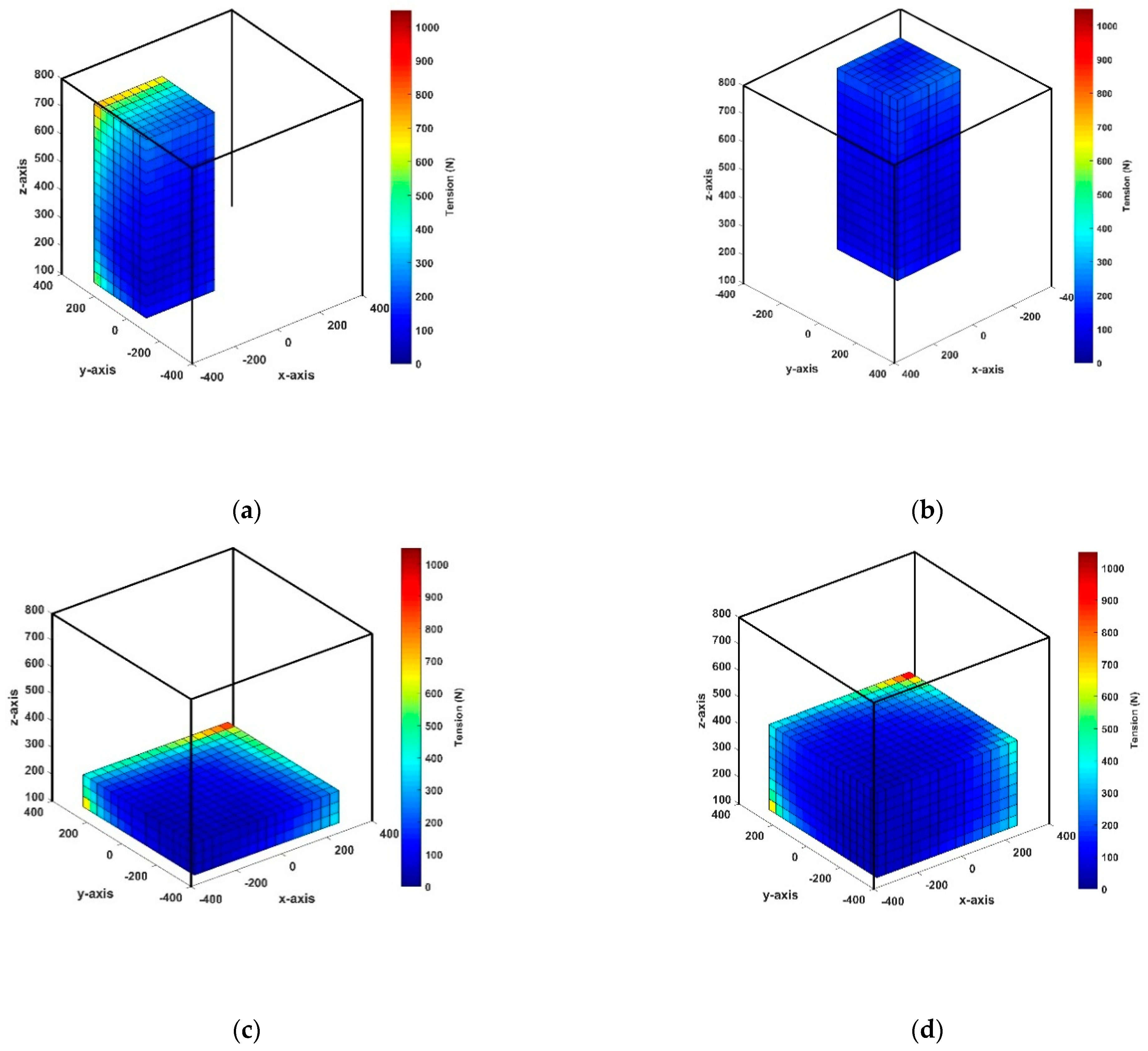
Figure 9a,b show the quarter section of the wrench-feasible workspace in the simulation results, and they provide detailed information on the internal workspace and show that both quarter sections were filled with blue boxes. The cable tension distribution in the interior of the workspace is shown to be relatively low, with an average value of approximately 100 N. Therefore, these results were desirable. Additionally, Figure 9c,d show the workspace results at Z = 0.2 m and Z = 0.4 m, respectively. It is obvious that the blue boxes comprised the bulk of the internal workspace and the tension was similar in these two diagrams. However, the high-tension distribution appeared at the corner of its slice and the vicinities of this position. 
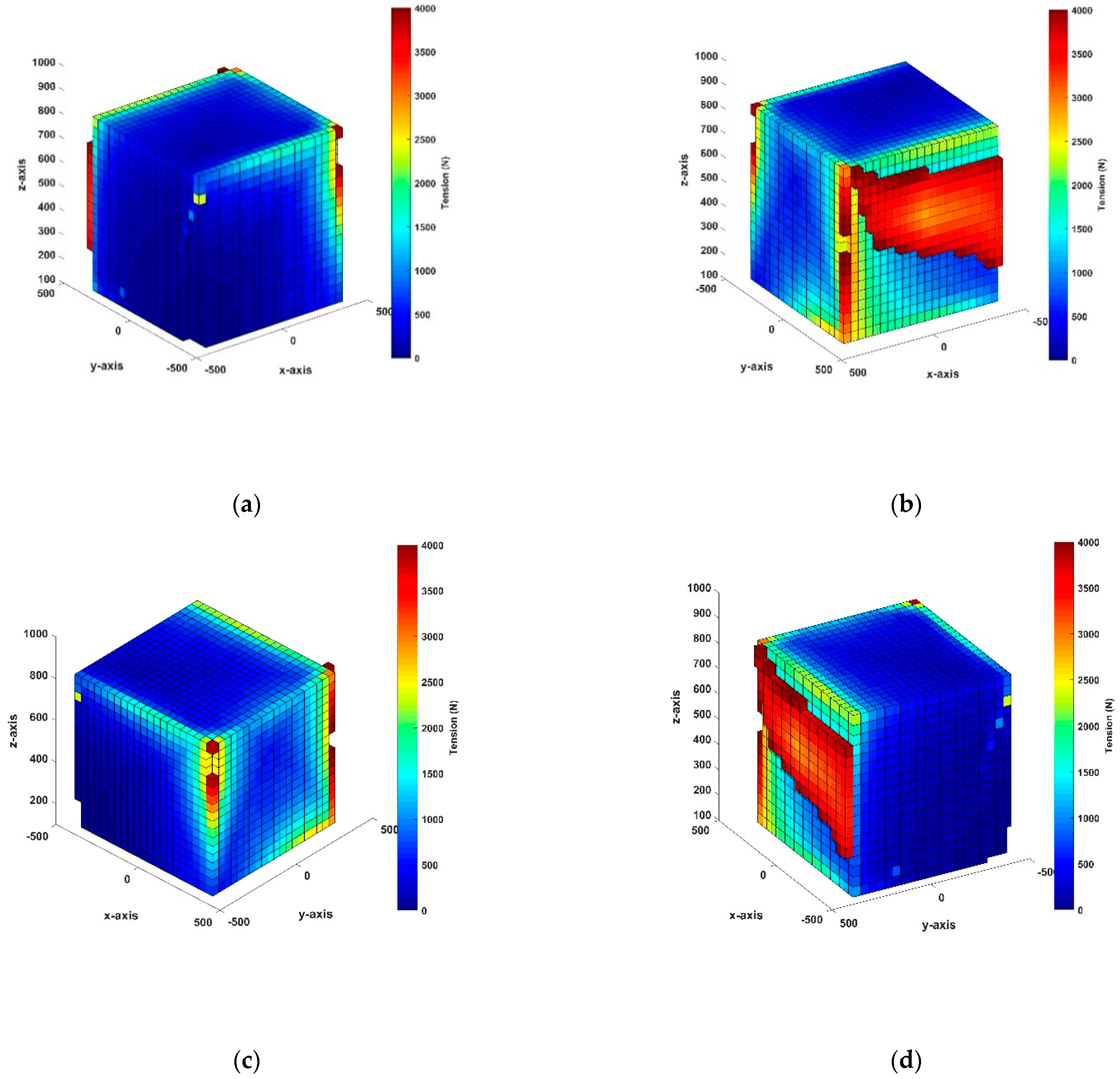
Figure 10a–d show the wrench-feasible workspace of CDPR when extending the moving ranges in the X and Y directions from 0.6 m to 0.8 m and the Z-axis from 0.1 m to 0.8 m. The applied acceleration was 100 m/s2. In these figures, it can be seen that both faces of the back view in the X and Y directions had the highest cable tension and appeared in regions that were eliminated from the workspace because they exceeded the constraint in the range of 0 ≤ Ti ≤ 4000 N. This shows that the simulation results were suitable for the wrench-feasible workspace of the proposed CDPR system as well as the real system due to the necessity of having a safe working space to prevent collisions between the end-effector and the frame during work. Therefore, extensions of the moving range directions and the high-tension distribution, which occurred at the vertical edges of the workspace, should be considered. In addition, compared with results from previous related studies in [4,22,32], the research results of the paper show that under the same conditions of motion acceleration, the end-effector range of motion is smaller but the wrench-feasible workspace analysis results are significantly improved. This indicates the effectiveness of the proposed method.

5. Conclusions

In this work, kinematics and dynamics were obtained for a proposed CDPR system. An overall workspace was analyzed for the CDPR system considering nonlinear tension. Then, experiments were conducted to identify the dynamic modulus of elasticity based on the DMA method, and the results showed that the dynamic modulus depends on various frequencies. Based on the nonlinear cable model, the kinematics equation that includes the nonlinear model was modified and an overall workspace analysis was carried out for a wrench-feasible workspace at various accelerations. As a result, the CDPR system was shown to have a large workspace. At the outer surface, high cable tension generally appeared at the vertices and edges of the simulation region. Moreover, as the acceleration increased, the whole tension increased, and the maximum tension was achieved at 100 m/s2. The workspace was satisfactory in the case of the end-effector moving in the X- and Y-axis limits from −0.3 to 0.3 m. When the axis ranges were increased from −0.4 to 0.4 m, the cable tensions exceeded the constrained condition, and these positions were eliminated from the workspace.

Author Contributions

Writing—original draft preparation, V.N.D.K.; writing—review and editing, V.N.D.K. and S.-C.H. All authors have read and agreed to the published version of the manuscript.

Funding

The authors acknowledge and thank the Ministry of Science and Technology of the Republic of China for their partial financial support of this study under Contract Number MOST 110-2221-E-992-062.

Institutional Review Board Statement

Not applicable.

Informed Consent Statement

Not applicable.

Data Availability Statement

Not applicable.

Conflicts of Interest

The authors declare no conflict of interest.

References

  1. Meunier, G.; Boulet, B.; Nahon, M. Control of an Overactuated Cable-Driven Parallel Mechanism for a Radio Telescope Application. IEEE Trans. Control. Syst. Technol. 2009, 17, 1043–1054. [Google Scholar] [CrossRef]
  2. Zi, B.; Lin, J.; Qian, S. Localization obstacle avoidance planning and control of a cooperative CDPR for multiple mobile cranes. Robot. Comput. Integr. Manuf. 2015, 34, 105–123. [Google Scholar] [CrossRef]
  3. Chen, Q.; Zi, B.; Sun, Z.; Li, Y.; Xu, Q. Design and Development of a New Cable-Driven Parallel Robot for Waist Rehabilitation. IEEE/ASME Trans. Mechatron. 2019, 24, 1497–1507. [Google Scholar] [CrossRef]
  4. Xin, M. Kinematics Dynamics and Controller Design for the Contour Crafting Cartesian Cable (C4) Robot. Master’s Thesis, Ohio University, Athens, OH, USA, 2008. [Google Scholar]
  5. Kraus, W. Force Control of Cable-Driven Parallel Robot. Ph.D. Thesis, Stuttgart University, Stuttgart, Germany, 2015. [Google Scholar]
  6. Caverly, R.J.; Forbes, J.R. Dynamic Modeling and Noncollocated Control of a Flexible Planar Cable-Driven Manipulator. IEEE Trans. Robot. 2014, 30, 1386–1397. [Google Scholar] [CrossRef]
  7. Begey, J.; Cuvillon, L.; Lesellier, M.; Gouttefarde, M.; Gangloff, J. Dynamic Control of Parallel Robots Driven by Flexible Cables and Actuated by Position-Controlled Winches. IEEE Trans. Robot. 2018, 35, 286–293. [Google Scholar] [CrossRef]
  8. Rezaiee-Pajand, M.; Mokhtari, M.; Masoodi, A.R. A novel cable element for nonlinear thermo-elastic analysis. Eng. Struct. 2018, 167, 431–444. [Google Scholar] [CrossRef]
  9. Schmidt, V.; Pott, A. Increase of Position Accuracy for Cable-Driven Parallel Robots Using a Model for Elongation of Plastic Fiber Ropes. In New Trends in Mechanism and Machine Science; Wenger, P., Flores, P., Eds.; Springer: Cham, Switzerland, 2017; Volume 43, pp. 335–343. [Google Scholar]
  10. Miyasaka, M.; Haghighipanah, M.; Li, Y.; Hannaford, B. Hysteresis model of longitudinally loaded cable for cable driven robots and identification of the parameters. In Proceedings of the 2016 IEEE International Conference on Robotics and Automation (ICRA), Stockholm, Sweden, 16–21 May 2016; pp. 4051–4057. [Google Scholar]
  11. Choi, S.-H.; Park, J.-O.; Park, K.-S. Tension analysis of a 6-degree-of-freedom cable-driven parallel robot considering dynamic pulley bearing friction. Adv. Mech. Eng. 2017, 9, 1687814017714981. [Google Scholar] [CrossRef]
  12. Kieu, D.-V.N.; Huang, S.-C. Dynamic Creep Phenomenon on Polymer Cable with Non-linear Characteristics for Cable-driven Parallel Robots. In Proceedings of the 2020 IEEE Eurasia Conference on IOT, Communication and Engineering (ECICE), Yunlin, Taiwan, 23–25 October 2020; pp. 378–380. [Google Scholar]
  13. Barrette, G.; Gosselin, C. Determination of the Dynamic Workspace of Cable-Driven Planar Parallel Mechanisms. J. Mech. Des. 2005, 127, 242–248. [Google Scholar] [CrossRef]
  14. Bosscher, P.; Williams, R.L., II; Bryson, L.S.; Castro-Lacouture, D. Cable-suspended robotic contour crafting system. Autom. Constr. 2007, 17, 45–55. [Google Scholar] [CrossRef]
  15. Pham, C.B.; Yeo, S.H.; Yang, G.; Kurbanhusen, M.S.; Chen, I.-M. Force-closure workspace analysis of cable-driven parallel mechanisms. Mech. Mach. Theory 2006, 41, 53–69. [Google Scholar] [CrossRef]
  16. Loloei, A.Z.; Aref, M.M.; Taghirad, H.D. Wrench feasible workspace analysis of cable-driven parallel manipulators using LMI approach. In Proceedings of the 2009 IEEE/ASME International Conference on Advanced Intelligent Mechatronics, Singapore, 14–17 July 2009; pp. 1034–1039. [Google Scholar] [CrossRef]
  17. Chawla, I.; Pathak, P.M.; Notash, L.; Samantaray, A.K.; Li, Q.; Sharma, U.K. Workspace analysis and design of large-scale cable-driven printing robot considering cable mass and mobile platform orientation. Mech. Mach. Theory 2021, 165, 104426. [Google Scholar] [CrossRef]
  18. Jamshidifar, H.; Khajepour, A.; Korayem, A.H. Wrench Feasibility and Workspace Expansion of Planar Cable-Driven Parallel Robots by a Novel Passive Counterbalancing Mechanism. IEEE Trans. Robot. 2020, 37, 935–947. [Google Scholar] [CrossRef]
  19. Zake, Z.; Chaumette, F.; Pedemonte, N.; Caro, S. Control Stability Workspace for a Cable-Driven Parallel Robot Controlled by Visual Servoing. In Cable-Driven Parallel Robots: Proceedings of the 5th International Conference on Cable-Driven Parallel Robots; Mechanisms and Machine Science; Springer: Cham, Switzerland, 2021; Volume 104. [Google Scholar]
  20. Handojo, V.A.; Syamlan, A.T.; Nurahmi, L.; Pramujati, B.; Tamara, M.N.; Wasiwitono, U. Cable Driven Parallel Robot with Big Interference-Free Workspace. In Mechanism and Machine Science; Sen, D., Mohan, S., Ananthasuresh, G., Eds.; Lecture Notes in Mechanical Engineering; Springer: Singapore, 2021. [Google Scholar]
  21. Lau, D.; Eden, J.; Oetomo, D.; Halgamuge, S.K. Musculoskeletal Static Workspace Analysis of the Human Shoulder as a Cable-Driven Robot. IEEE/ASME Trans. Mechatron. 2014, 20, 978–984. [Google Scholar] [CrossRef] [Green Version]
  22. Heo, J.-M.; Park, B.-J.; Park, J.-O.; Kim, C.-S.; Jinwoo, J. Workspace and stability analysis of a 6-DOF cable-driven parallel robot using frequency-based variable constraint. J. Mech. Sci. Technol. 2018, 32, 1345–1356. [Google Scholar] [CrossRef]
  23. Pott, A. Influence of Pulley Kinematics on Cable-Driven Parallel Robots. In Latest Advances in Robot Kinematics; Springer: Dordrecht, The Netherlands, 2012; pp. 197–204. [Google Scholar]
  24. Kraus, W.; Kessler, M.; Pott, A. Pulley friction compensation for winch-integrated cable force measurement and verification on a cable-driven parallel robot. In Proceedings of the 2015 IEEE International Conference on Robotics and Automation (ICRA), Seattle, WA, USA, 26–30 May 2015; pp. 1627–1632. [Google Scholar]
  25. Baklouti, S.; Courteille, E.; Caro, S.; Dkhil, M. Dynamic and Oscillatory Motions of Cable-Driven Parallel Robots Based on a Nonlinear Cable Tension Model. J. Mech. Robot. 2017, 9, 061014. [Google Scholar] [CrossRef]
  26. Tempel, P.; Miermeister, P.; Lechler, A.; Pott, A. Modelling of Kinematics and Dynamics of the IPAnema 3 Cable Robot for Simulative Analysis. Appl. Mech. Mater. 2015, 794, 419–426. [Google Scholar] [CrossRef]
  27. Pott, A.; Mütherich, H.; Kraus, W.; Schmidt, V.; Miermeister, P.; Verl, A. Ipanema: A family of Cable-Driven Parallel Robots for Industrial Applications. In Cable-Driven Parallel Robots; Mechanisms and Machine Science; Springer: Berlin/Heidelberg, Germany, 2013; pp. 119–134. [Google Scholar]
  28. Miermeister, P.; Kraus, W.; Lan, T.; Pott, A. An elastic cable model for cable-driven parallel robots including hysteresis effects. In Cable-Driven Parallel Robots; Springer: Cham, Switzerland, 2015; pp. 17–28. [Google Scholar]
  29. Menard, K.P. Dynamic Mechanical Analysis: A Practical Introduction, 2nd ed.; CRC Press: Boca Raton, FL, USA, 2008; ISBN 9781420053128. [Google Scholar]
  30. Gouttefarde, M.; Gosselin, C.M. Analysis of the wrench-closure workspace of planar parallel cable-driven mechanisms. IEEE Trans. Robot. 2006, 22, 434–445. [Google Scholar] [CrossRef]
  31. Bosscher, P.; Riechel, A.; Ebert-Uphoff, I. Wrench-feasible workspace generation for cable-driven robots. IEEE Trans. Robot. 2006, 22, 890–902. [Google Scholar] [CrossRef]
  32. Heo, J.-M.; Choi, S.-H.; Park, K.-S. Workspace analysis of a 6-DOF cable-driven parallel robot considering pulley bearing friction under ultra-high acceleration. Microsyst. Technol. 2016, 23, 2615–2627. [Google Scholar] [CrossRef]
Figure 1. Schematic diagram of the CDPR system: (a) diagram of 6–DOF CDPR; (b) asymmetric pulley locations.
Applsci 12 00244 g001
Figure 2. Diagrammatic representation of the kinematic parameter.
Applsci 12 00244 g002
Figure 3. Diagrammatic representation of the pulley kinematics.
Applsci 12 00244 g003
Figure 4. Flowchart of the proposed method.
Applsci 12 00244 g004
Figure 5. Experimental setup.
Applsci 12 00244 g005
Figure 6. Sinusoidal force causing sinusoidal elongation at different frequencies: (a) 0.1 Hz; (b) 1 Hz; (c) 2 Hz; (d) 5 Hz.
Applsci 12 00244 g006aApplsci 12 00244 g006b
Figure 7. Overall workspace simulation at the acceleration of 10 m/s2: (a) front plane of the X–axis; (b) back plane of the X–axis; (c) front plane of the Y–axis; (d) back plane of the Y–axis.
Applsci 12 00244 g007
Figure 8. Overall workspace simulation at the acceleration of 100 m/s2: (a) front plane of the X–axis; (b) back plane of the X–axis; (c) front plane of the Y–axis; (d) back plane of the Y-axis.
Applsci 12 00244 g008aApplsci 12 00244 g008b
Figure 9. Quarter section of overall workspace simulation at the acceleration of 100 m/s2: (a) quarter section of X–direction; (b) quarter section of Y–direction; (c) section view of Z = 0.2 m; (d) section view of Z = 0.4 m.
Applsci 12 00244 g009
Figure 10. The wrench-feasible workspace simulation at the acceleration of 100 m/s2 when extending the axis ranges: (a) front plane of the X–axis; (b) back plane of the X–axis; (c) front plane of the Y–axis; (d) back plane of the Y–axis.
Applsci 12 00244 g010
Table 1. Coordinates of the pulley.
PulleysX (m)Y (m)Z (m)
P1−0.4550.5400.884
P20.4550.5400.880
P3−0.445−0.5400.860
P40.455−0.5400.881
P5−0.5400.4650.075
P60.5400.4550.071
P7−0.540−0.4550.073
P80.540−0.4550.072
Table 2. Parameters of the modulus of elasticity of the Dynamica cable at various frequencies.
Freq (Hz)σmax (MPa)εmaxE* (GPA)E′ (GPA)φ (Deg)η
0.153.1555.6877 10−493.592.634.70.14
153.545.2031 10−4102.975.57.030.93
253.4745.2052 10−4102.775.47.030.93
553.4424.9898 10−4107.178.216.40.94
Publisher’s Note: MDPI stays neutral with regard to jurisdictional claims in published maps and institutional affiliations.

