Article

Regulation Principles of Power Flow Gradients to Multiple Characteristic Independent Variables in UPFC Embedded Power System

1
Department of Electrical Engineering, Zhejiang University, Hangzhou 310027, China
2
National Power Dispatching and Control Center, State Grid Corporation of China, Beijing 100032, China
*
Author to whom correspondence should be addressed.
Appl. Sci. 2020, 10(5), 1720; https://doi.org/10.3390/app10051720
Submission received: 16 February 2020 / Revised: 27 February 2020 / Accepted: 28 February 2020 / Published: 3 March 2020
(This article belongs to the Special Issue Power Electronic Applications in Power and Energy Systems)

Abstract

:
The power flows in the unified power flow controller (UPFC) embedded system is mainly regulated by the two variables containing the magnitude and the phase angle of the output series inserted voltage (OSIV) of UPFC. Different value combinations of the two variables can form multiple regulation modes of OSIV, and the regulation principles and efficiencies for power flows are distinct by different regulation modes. This paper dedicates to research the regulation principles of active and reactive power flow gradients (PFG) to multiple characteristic independent variables (CIVs) at several selected critical points (SCP) of the system in different operation conditions. The CIVs contains the magnitude of OSIV, the phase angle of OSIV, and the phase difference of the system. First, multiple power flow regulation modes of OSIV are designed, the mathematical models of the PFG to each CIV at each SCP are established, and the theoretical principles for the PFG to each CIV at each SCP are analyzed and compared. Next, four typical operation conditions of the system and four regulation scenarios are assumed and case studies for the PFG to each CIV at different SCP are carried out. The test results at each SCP are analyzed both in the two-dimensional planes and three-dimensional spaces. The regulation principles and efficiencies of PFG to each CIV at different SCP are compared with each other and summarized, which can offer useful references for practical engineering and applications of UPFC.

1. Introduction

Over the recent years, the unified power flow controller (UPFC) has been widely recognized as one of the most advanced flexible alternate current systems (FACTS) devices with versatile functionalities of regulating the power systems. Among all the functions, the regulation of the power flows in the transmission system has usually been the most primary and general function of UPFC in applications. More and more concerns are being attracted regarding the modelling and control of the power flow regulations by UPFC [1,2,3,4,5].
Amounts of researches on the equivalent power flow modelling of UPFC have been conducted in [6,7,8,9,10,11,12,13]. In [6], the real and reactive power references were tracked based on UPFC’s discrete sliding mode technique. Experts in [7,8] established the mathematical models of UPFC considering operation constraints or operational characteristics. The steady-state and dynamic power flow models of UPFC were specifically built in [9,10]. In [11], several operation modes of UPFC were researched individually to estimate the power system state. In [12,13] a current based model and dc-based model of UPFC were also proposed, in order to improve the load flows of the system. Moreover, the authors in [14] researched an optimal power flow model of UPFC based on preventive security constraints to increase the economic efficiency and static security of the power system.
However, in the above studies, the output of the series converters in UPFC are mostly equivalent to voltage sources with alterable magnitudes and phase angles, and they are only integrated into the mathematical models of the UPFC embedded system to realize special requirements of power flows, but the detailed regulation principles of the power flow changing rates or gradients dependent on the magnitudes and phase angles of the voltage sources are usually ignored.
There are also a lot of studies carried out regarding the power flow control and applications in [15,16,17,18,19,20,21]. The optimal power flow control methods of UPFC aiming to improve the transfer capability of the system are studied in [15,16]. A hybrid electromagnetic model of UPFC with more flexibility was proposed in [17]. In [18], a new real time Lyapunov based controller in UPFC was investigated to improve the power quality. In [19,20,21], several power flow control strategies and approaches of UPFC were designed for damping the power flow oscillations and enhancing the power system stability. However, most of these power flow control methods or applications of UPFC concentrate on realizing the presupposed power flow regulation targets or purposes more precisely and smoothly through improving the power flow regulation capabilities or performances by UPFC. The detailed power flow regulation processes and efficiencies dependent on the characteristic variables such as the magnitudes and phase angles of the OSIV of UPFC have never been researched and remain to be evaluated specifically.
The power flows in the system might fluctuate intensely within certain short periods during the regulation processes by UPFC, especially when the power flow references are being regulated by larger ranges or scales. On this occasion, potential perturbations or shocks may inevitably be exerted on the system by the impulsive power flows, such as surge current, unbalanced electromotive forces, power angle swings, booming thermal energy at certain points, and so on. In these cases, the stabilities of the power angle, the frequency or the voltage of the system are more likely to fluctuate or deteriorate by some extent. It is thus essential to research and outline the specific changing rates of the power flows or PFG during the regulation processes of UPFC.
Moreover, the PFG at different positions from the sending end to receiving end of the power system have become different after the insertions of UPFC. The PFG on the system at different positions may also change by some extents when the power flow references are being regulated by different the ranges, scales, steps and directions. Accordingly, the resulting influences on different positions of the system by the PFG are different and uncertain. It is requisite to outline the PFG at several representative and critical positions of the power system, to evaluate their severities of influences on the power system.
Furthermore, when the power flows in the system are being regulated by the magnitude and phase angle of OSIV individually or comprehensively, there may be multiple regulation modes by the two variables of OSIV, and the regulation effectiveness or efficiencies are also different by different regulation modes. When the phase difference of the system varies, the regulation efficiencies may also change by some extent even the regulation modes remain the same. Therefore, it is also necessary to explore and compare the different PFG dependent on different CIVs including the magnitude of OSIV, the phase angle of OSIV, and the phase differences of the system in different operation conditions.
For the purpose of achieving the above objectives, this paper is intended to research and compare the regulation principles and efficiencies of the power flow gradients to multiple characteristic independent variables by multiple regulation modes at several critical points of the UPFC embedded power system. The mathematical model of the PFG to each CIV at each SCP are constructed based on a specific real circuit of UPFC embedded system, and the tests and analysis are conducted in different typical operation conditions, so as to outline the PFG principles more practically and comprehensively.
The organization of this paper is as below. In Section 2, the mathematical model and theoretical analysis for the PFG to CIVs are achieved. In Section 3, case studies for the PFG to each CIV at different SCP are carried out and analyzed in two-dimensional planes and three-dimensional spaces. The main conclusions are summarized in the last section.

2. Modelling and Theoretical Analysis for Power Flow Gradients

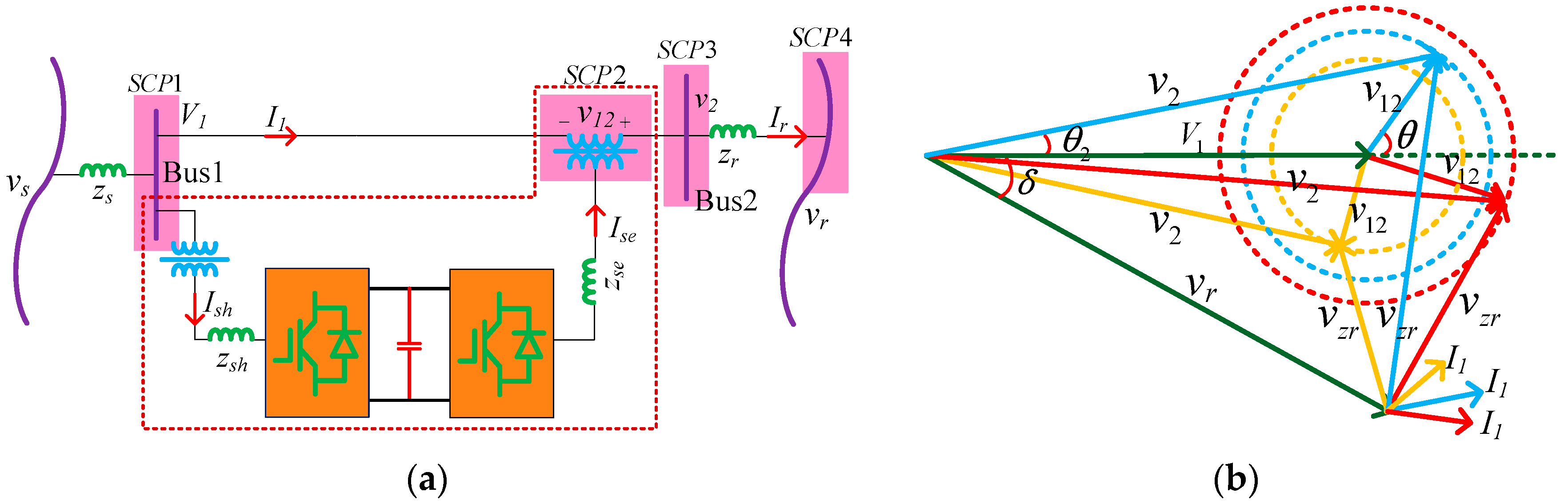
2.1. Power Flow Regulation Theories by the OSIV of UPFC

The general UPFC embedded power system is shown in (a) of Figure 1, and the structure of UPFC is encircled by dotted red lines. The UPFC is mainly constituted by two back to back converters which are linked together by one common dc capacitor. The converter connected to Bus1 is generally named the shunt converter, which can maintain the voltages of Bus1 and dc link constant. The other back-to back converter is known as the series converter, which can insert a varying voltage source into the transmission lines. The schematic diagram of UPFC embedded system based on specific real circuit is shown in (a) of Figure 1.
As is known, the regulations for the power flows in the system by UPFC are dominated by the OSIV of the UPFC. According to the phasor diagram in (b) of Figure 1, there are two regulation variables of OSIV containing the magnitude of OSIV and the phase angle θ of OSIV. When the magnitude of OSIV changes, or the phase angle θ of OSIV rotates, the phasor of the voltage v2 of Bus2 will also vary, thus the active and reactive power flows in the system changes accordingly. Here, one special regulation mode is assumed as the specific value combinations of the magnitude of OSIV and the phase angle θ of OSIV. When the two regulation variables are being regulated individually or comprehensively, there will be multiple regulation modes by OSIV the regulation effectiveness or efficiencies for power flows may also be different by various regulation modes of the two variables of OSIV.
Moreover, as the phasor of the voltage V1 of Bus1 is assumed constant and fixed at the initial position in (b) of Figure 1, when the system operation condition changes, meaning the phase difference δ and the voltage of vr vary by some extent. In the case that even the magnitude and phase angle of OSIV are kept unchanged, the current I1 through the transmission line will also vary, resulting that the power flows in the system change accordingly.
Upon the above discussions, the power flows in the system may change with the magnitude of v12, the phase angle θ of v12, the phase difference δ and the magnitude of vr. As the magnitude of vr usually varies within small limited ranges, only the former three variables are assumed as the characteristic independent variables. For convenience, the magnitude of v12, the phase angle θ of v12, the phase difference δ are assumed as CIV1, CIV2, and CIV3, respectively.

2.2. Mathematical Model for all the PFG to CIVs

In order to outline the power flow gradients at different representative points of the system, the Bus1, OSIV, Bus2, and the receiving end bus of the system are assumed as the four selected critical points (SCP). Then, SCP1 stands for the voltage V1 of Bus1, SCP2 denotes the voltage v12 of OSIV, SCP3 represents the voltage of Bus2, and SCP4 stands for the voltage vr, all the SCPs have also been highlighted in (a) of Figure 1.
First of all, the primary variables of the model are assumed as, V 1 = 1 0 , v 12 = v 12 θ , v r = v r δ , z r = r r + j x r . Based on the original power flow model of the UPFC embedded power system at different SCPs in Appendix A of [22], the PFG to each CIV at different SCP are derived out. Each equation is comprised of two parts containing the active power flow gradients (APFG) and reactive power flow gradients (RPFG) to each CIV, and all the equations are listed as below.
Here, Pj, Qj specifies the active and reactive power flows at SCPj, and j stands for the number of SCP. dPj/dv12 and dQj/dv12 stand for the APFG to CIV1 and RPFG to CIV1 at SCPj, respectively. dPj/ and dQj/ mean the APFG to CIV2 and RPFG to CIV2 at SCPj, respectively, and dPj/ and dQj/ represent the APFG to CIV3 and RPFG to CIV3 at SCPj, respectively.
The PFG to each CIV at Bus1 (SCP1) are deduced as Equations (1)–(3),
{ d P 1 / d v 12 = V 1 ( r r cos θ + x r sin θ ) / z r 2 d Q 1 / d v 12 = V 1 ( x r cos θ r r sin θ ) / z r 2
{ d P 1 / d θ = V 1 v 12 ( x r cos θ r r sin θ ) / z r 2 d Q 1 / d θ = V 1 v 12 ( r r cos θ + x r sin θ ) / z r 2
{ d P 1 / d δ = V 1 v r ( r r sin δ x r cos δ ) / z r 2 d Q 1 / d δ = V 1 v r ( r r cos δ + x r sin δ ) / z r 2
The PFG to each CIV at SCP2 are derived out as Equations (4)–(6),
{ d P 12 / d v 12 = V 1 ( r r cos θ + x r sin θ ) / z r 2 d Q 12 / d v 12 = V 1 ( x r cos θ r r sin θ ) / z r 2
{ d P 12 / d θ = v 12 { V 1 ( x r cos θ + r r sin θ ) + v r [ r r sin ( δ θ ) x r cos ( δ θ ) ] } / z r 2 d Q 12 / d θ = v 12 { V 1 ( x r sin θ r r cos θ ) + v r [ r r cos ( δ θ ) + x r sin ( δ θ ) ] } / z r 2
{ d P 12 / d δ = v 12 v r [ r r sin ( δ θ ) x r cos ( δ θ ) ] / z r 2 d Q 12 / d δ = v 12 v r [ r r cos ( δ θ ) + x r sin ( δ θ ) ] / z r 2
The PFG to each CIV at SCP3 are carried out as Equations (7)–(9),
{ d P 2 / d v 12 = { 2 r r ( v 12 + V 1 cos θ ) v r [ r r cos ( δ θ ) + x r sin ( δ θ ) ] } / z r 2 d Q 2 / d v 12 = { 2 x r ( v 12 + V 1 cos θ ) + v r [ r r sin ( δ θ ) x r cos ( δ θ ) ] } / z r 2
{ d P 2 / d θ = v 12 { 2 V 1 r r sin θ + v r [ r r sin ( δ θ ) x r cos ( δ θ ) ] } / z r 2 d Q 2 / d θ = v 12 { 2 V 1 x r sin θ + v r [ r r cos ( δ θ ) + x r sin ( δ θ ) ] } / z r 2
{ d P 2 / d δ = v r { V 1 ( r r sin δ x r cos δ ) + v 12 [ r r sin ( δ θ ) x r cos ( δ θ ) ] } / z r 2 d Q 2 / d δ = v r { V 1 ( r r cos δ + x r sin δ ) + v 12 [ r r cos ( δ θ ) + x r sin ( δ θ ) ] } / z r 2
The PFG to each CIV at SCP4 at SCP4 are deduced as Equations (10)–(12),
{ d P r / d v 12 = v r [ r r cos ( δ θ ) x r sin ( δ θ ) ] / z r 2 d Q r / d v 12 = v r [ r r sin ( δ θ ) + x r cos ( δ θ ) ] / z r 2
{ d P r / d θ = v 12 v r [ r r sin ( δ θ ) + x r cos ( δ θ ) ] / z r 2 d Q r / d θ = v 12 v r [ x r sin ( δ θ ) r r cos ( δ θ ) ] / z r 2
{ d P r / d δ = v r { V 1 ( x r cos δ + r r sin δ ) + v 12 [ x r cos ( δ θ ) + r r sin ( δ θ ) ] } / z r 2 d Q r / d δ = v r { V 1 ( x r sin δ r r cos δ ) + v 12 [ x r sin ( δ θ ) r r cos ( δ θ ) ] } / z r 2

2.3. Theoretical Analysis for Regulation Principles of the PFG to CIVs

Foremost, it is essential to illuminate the regulation meanings or targets for PFG to CIVs by UPFC. When the CIVs are regulated to certain levels or regions, the APFG and RPFG to CIVs at different SCP will also change to new levels or regions, therefore the power flows will transmit to the requisite values by higher or lower efficiencies.
To be specific, if the power flow gradients are regulated to a higher level, the power flows in the system are changing much more intensely. In this case, the regulation efficiencies or changing rate of power flows are higher and the power flows can transmit to the requisite values more rapidly. However, the resulting impulsive shocks to the system are more serious at the same time.
In contrast, if the power flow gradients are regulated to a lower level, the power flows in the system are changing much more mildly, the regulation efficiencies or changing rate of power flows are lower and the power flows may transmit to the required values more slowly. Moreover, the resulting impulsive shocks to the system are weaker at the same time.
Next, according to the mathematical model above, the regulation principles of all the PFG to each CIV at each SCP can be carried out theoretically.
First of all, according to Equations (1)–(3), the PFG to CIV1 are only dependent on CIV2 of phase angle θ, and similarly, the PFG to CIV3 are only dependent on CIV3. However, the PFG to CIV2 is dependent on CIV1 and CIV3 simultaneously. Therefore, the PFG to CIV1 and CIV3 at SCP1 can both be regulated by one CIV, namely that they have both only one degree of freedom for regulations. In contrast, the PFG to CIV2 has one more degrees of freedom for regulations by UPFC, therefore, the regulation modes or manners for PFG to CIV2 are more complicated and sufficient.
Based on Equations (4)–(6) for the PFG at SCP2, the PFG to CIV1 are similar to that of SCP1, yet the PFG to CIV2 and CIV3 both depend on all the three CIVs; therefore, they both have three degrees of freedom for regulations by UPFC, indicating that the PFG at SCP2 can be regulated more complicatedly and sufficiently than that of SCP1.
According to Equations (7)–(9), the PFG at SCP3 are all dependent on three CIVs and they all have three degrees of freedom for regulation by UPFC, revealing that the PFG at SCP3 have become the most complicated and sufficient along the whole power system after the insertion of OSIV and the regulations by UPFC.
Similarly, based on Equations (10)–(12), the PFG to CIV1 at SCP4 is dependent on CIV2 and CIV3 has one degree of freedom, and the PFG to CIV2 and CIV3 at SCP4 both depend on three CIVs and have three degrees of freedom. Therefore, the PFG at SCP4 have similar complexity for regulations to that of SCP2.
In conclusion, the PFG at SCP1 have the fewest degrees of freedom and the simplest regulation principles for regulations by UPFC. The PFG at SCP2 and SCP4 have the similar degree of freedom for regulations by UPFC, and the PFG at SCP3 owns the most degrees of freedom and the most complicated regulation principles for regulations by UPFC, indicating that the PFG of the power system can be regulated by UPFC efficiently after the insertion of OSIV at SCP2.

3. Case Studies and Analysis

3.1. Settings of the System Operation Conditions and the Regulation Modes and Scenarios of CIVs

Based on the mathematical models above, a case study for the PFG at each SCP is carried out in this section. First, several typical system operation conditions are assumed in Table 1. The operation conditions are mainly concerning the voltage of vr and the phase difference δ. The first three conditions belong to the normal conditions, while the last condition is assumed as the severe condition.
In order to outline the regulation principles of the PFG to each CIV more comprehensively, the regulation modes of CIVs have also to be designed typically and effectively. The first two CIVs containing the magnitude and the phase angle θ of OSIV -are assumed to be regulated smoothly and simultaneously, while the CIV3 of phase difference δ is assumed as constant in one specific operation condition and changes to another value only when the system operation conditions changes. Here, the magnitude of OSIV is assumed to range from 0 p.u. to 4.0 p.u., and the phase angle θ of OSIV is assumed to range from −π to π. Then, when the CIV1 is being regulated to increment from 0 p.u. to 4.0 p.u., there are two possible regulation methods regarding CIV2. On the one hand, the CIV2 can be regulated to increment from −π to π step by step, which is assumed as Regulation 1 (Reg.1) mode. On the other hand, it can also be regulated to decrement from π to −π step by step which is assumed as Regulation 2 (Reg.2) mode. On the settings, the following case studies will be carried out by both the two regulation types containing Reg.1 and Reg.2 modes of OSIV. It should also be noted that if the magnitude of v12 become negative during the regulation process, it just means the OSIV are inserted into the system in the reverse directions.
Furthermore, in order to depict the regulation principles of PFG to CIV3 in as many operation conditions as possible, the phase difference δ must be assumed as continuous variables ranging from −π to π. On this occasion, the CIV1 still keep the previous varying ranges and modes, whereas the CIV2 is specifically designed as four different values in four typical regulation scenarios, which is listed in Table 2. Based on the settings, the regulation principles of PFG to CIV3 can be figured out more comprehensively.
Based on the above settings, the detailed regulation processes and principles can be outlined by the assumed regulation modes of CIV1 and CIV2, and the scenarios of CIV3 of UPFC. All the principles of the PFG to each CIV at different SCP will be tested and analyzed in the two-dimensional planes and three-dimensional spaces, respectively.

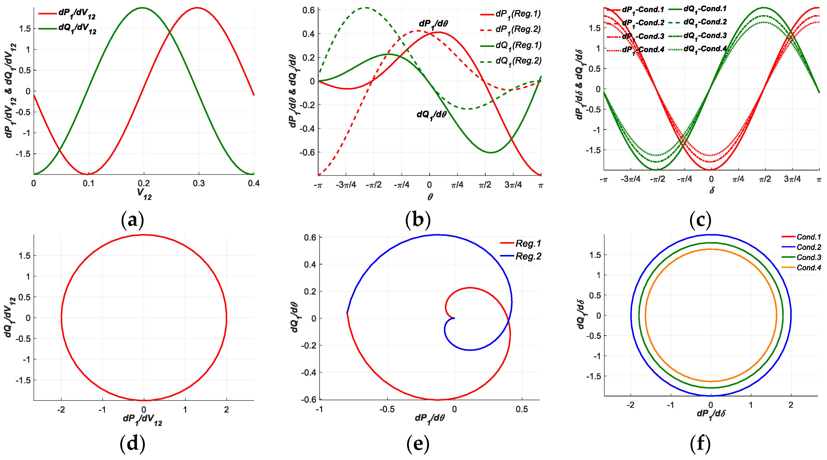
3.2. Test Results and Analysis for PFG at SCP1

First, the results of the PFG to each CIV at SCP1 are derived out and will be analyzed two-dimensional planes and three-dimensional spaces, respectively.

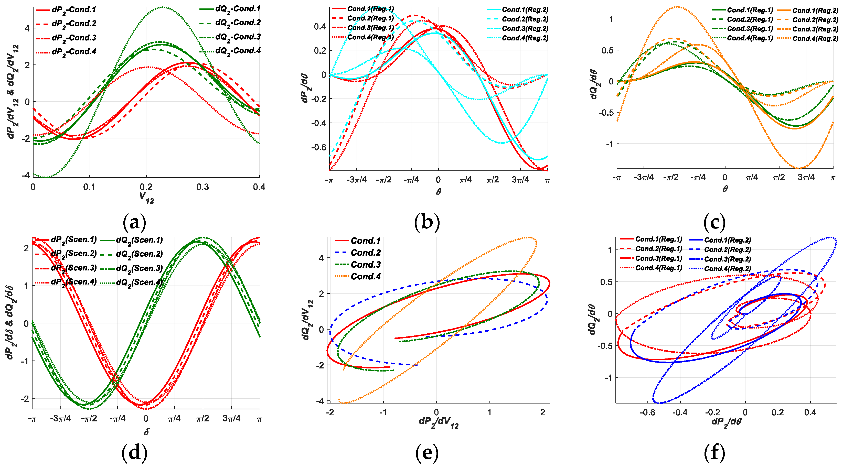
3.2.1. Test Results and Analysis in Two-Dimensional Planes

All the test results of the PFG to each CIV at SCP1 are listed in Figure 2. As shown in (a) of Figure 2, the APFG and RPFG to CIV1 at SCP1 both present sinusoidal curves, the fluctuation ranges of the two PFG are the same except the extreme values are different. In (b) of Figure 2, the PFG to CIV2 present more complicated sinusoids, the two curves of APFG to CIV2 by Reg.1 and Reg.2 modes are symmetrical about the y-axis through the origin, while those of RPFG to CIV2 show central or rotational symmetry features, both the APFG and RPFG at the positive and negative half regions have one larger amplitudes and one smaller amplitudes, indicating the PFG to CIV2 can be regulated to larger or smaller required amplitudes in different regions by different regulation modes. In (c) of Figure 2, all the curves of APFG and RPFG to CIV3 show sinusoidal features, the distinctions only lie in the magnitudes of the curves dependent on vr of different operation conditions. The above features are accordant with the theoretical analysis of the Equations (1)–(3).
Furthermore, the curves of (d)–(f) in Figure 2 depict the principles of PFG to each CIV from another perspective. In (d) of Figure 2, the curve of APFG to CIV1 against RPFG to CIV1 form a closed circular loop. In (e) of Figure 2, the two curves of APFG to CIV2 against RPFG to CIV2 by Reg.1 and Reg.2 modes also form a type of axial symmetrical closed shapes, manifesting that the PFG to CIV2 can be regulated throughout an overall closed region by the two regulation modes of CIV1 and CIV2, and the regulation modes are more efficient and practical. As for (f) of Figure 2, the APFG to CIV3 against RPFG to CIV3 still form closed circular loops in all the operation conditions. The above features of PFG to each CIV at SCP1 are also accordant with the theoretical analysis and Equations (1)–(3).

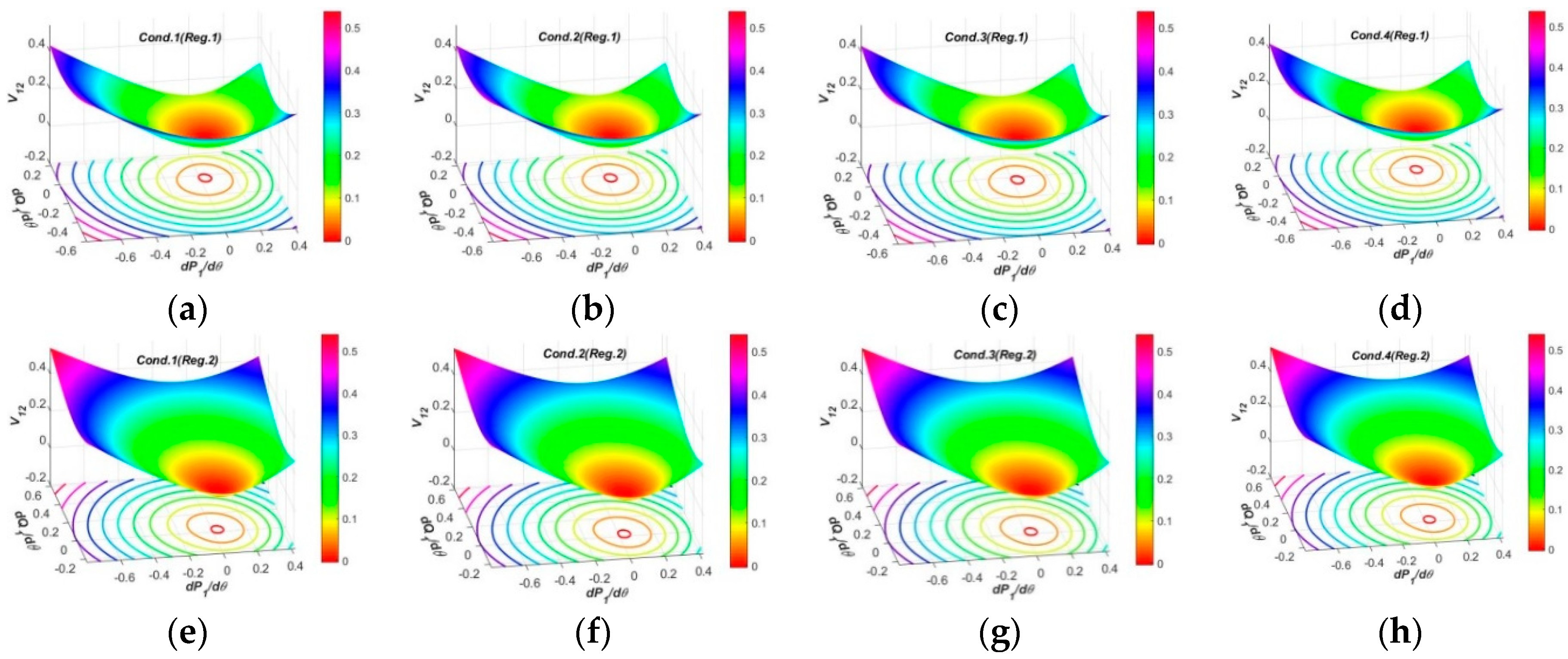
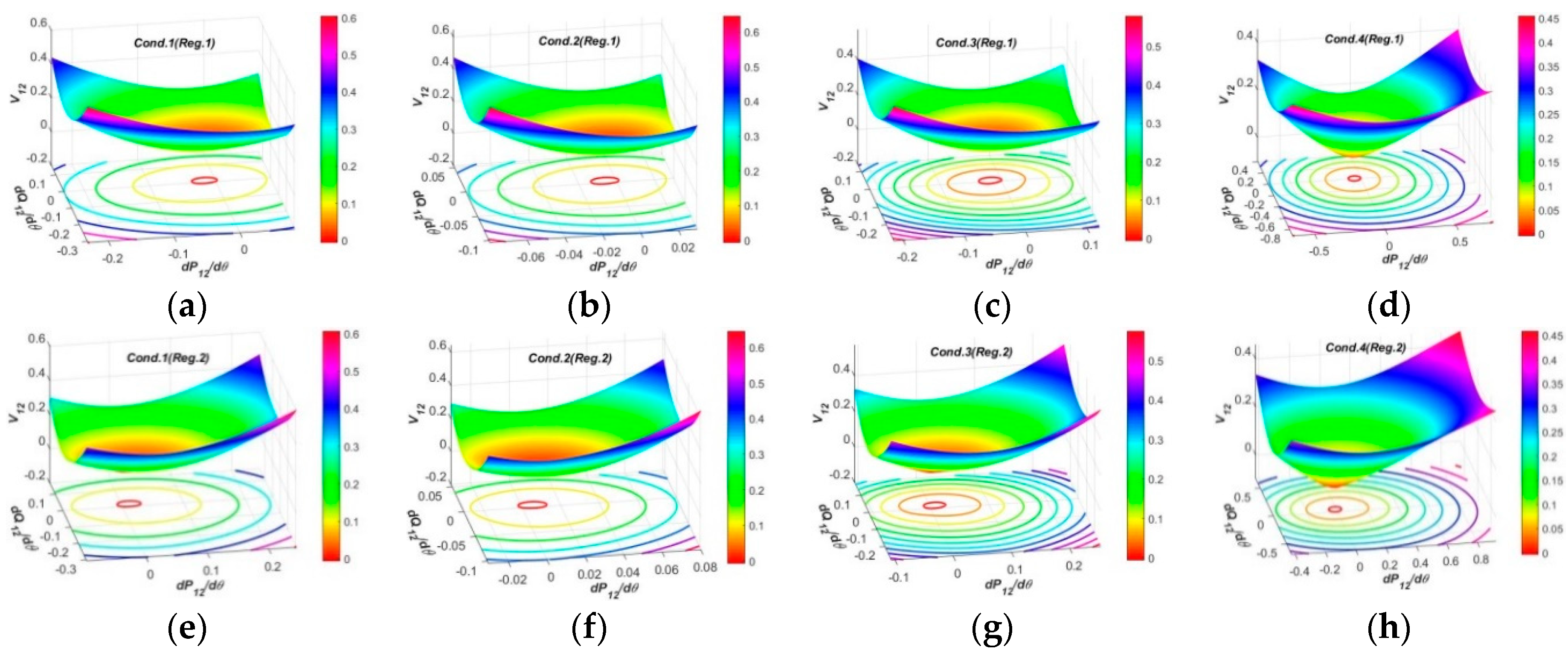
3.2.2. Test Results and Analysis in Three-Dimensional Spaces

In this section, the PFG to each CIV at SCP1 will be further analyzed in three-dimensional spaces.
According to Equations (1)–(3) and the theoretical analysis in Section 2.3, the PFG to CIV1 and CIV3 only have one degree of freedom for regulation and present simple principles, while the PFG to CIV2 has two degree of freedom for regulation and more complex principles. Therefore, only the principles of PFG to CIV2 in spaces are essential to be analyzed, and the spatial surfaces of PFG to CIV2 at SCP1 are listed in Figure 3.
On the one hand, the pictures in (a)–(d) of Figure 3 depict the spatial surfaces in all the operation conditions by Reg.1 mode of OSIV. It is evident that the spatial surfaces in all operation conditions present similar funnel shapes humping downwards, and the surface areas are proportional to CIV1. The difference among them mainly lie in the distribution positions of the projection loops on the P-Q plane regarding certain values of CIV1, revealing that the PFG to CIV2 at SCP1 are relatively uniform and have not been impacted much when the operation condition varies.
On the other hand, (e)–(h) of Figure 3 also describe the spatial surfaces in all the operation conditions by Reg.2 mode of OSIV. It can be seen that, the spatial surfaces in all the operation conditions still present similar shapes, but the surface area are larger than those of Reg.1 mode, revealing that the PFG to CIV2 at SCP1 by Reg.2 mode have larger regulation regions or redundancies and may be more adaptive to different regulation requirements.

3.3. Test Results and Analysis for PFG at SCP2

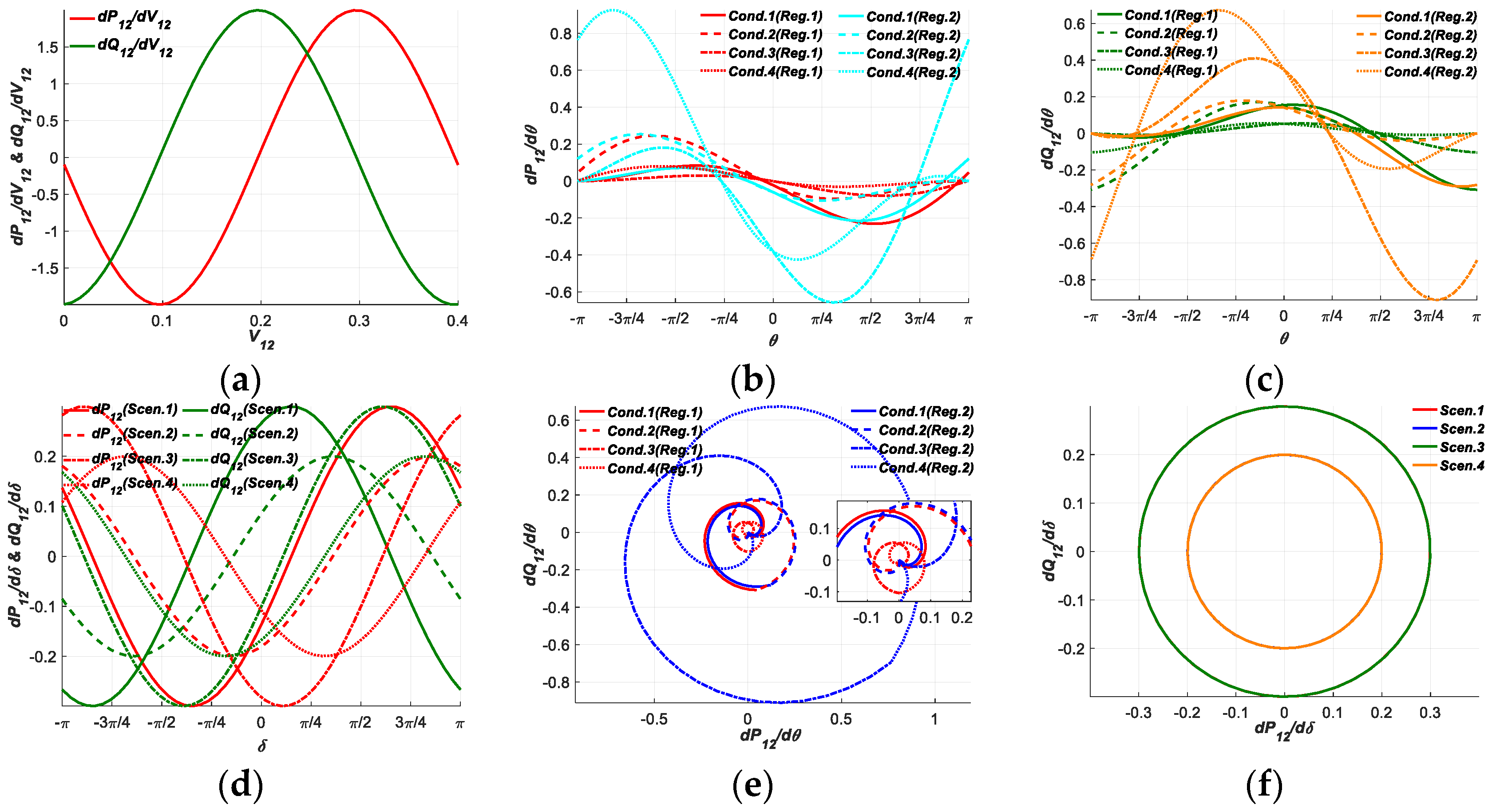
3.3.1. Test Results and Analysis in Two-Dimensional Planes

In this section, the PFG to each CIV at SCP2 will also be analyzed in planes similar as before.
It can be seen in (a) of Figure 4, the PFG to CIV1 at SCP1 almost present the same changing rules as that at SCP1. In (b) and (c) of Figure 4, the curves of APFG and RPFG to CIV2 at SCP2 present similar shapes analogous to sinusoids. The curves in the normal operation conditions by Reg.1 and Reg.2 modes almost focus within range of −0.2 p.u. to 0.2 p.u., while those in the severe operation condition by Reg.2 mode are two to four times larger, indicating that the PFG to CIV2 by Reg.2 mode are have more efficiencies and redundancies adapting to the severe operation conditions, but on this occasion, the resulting impulses or shocks to the power system during the regulation process may also be more intense, and the requirements for suppressing the resulting shocks are more rigorous at the same time. In (d) of Figure 4, the curves of APFG and RPFG regulated in the four regulation scenarios of CIV3 present sinusoidal shapes with different magnitudes and phases, revealing that the PFG to CIV3 can be regulated by various efficiencies in the four regulation scenarios, so as to adapt to all the operation conditions.
As the same as before, the pictures (e)–(f) of Figure 4 also reflect the principles of PFG to CIV from another viewpoint. In (e) of Figure 4, the curves of APFG to CIV2 against RPFG to CIV2 at SCP2 by Reg.1 and Reg.2 modes also form symmetrical closed shapes, the regulation ranges and areas by Reg.2 mode in the third and fourth operation condition are much larger than others. Referring to (f) of Figure 4, the curves of APFG against RPFG to CIV3 at SCP2 still form circular closed loops, and the areas of the loops can increase or decrease in different regulation scenarios.

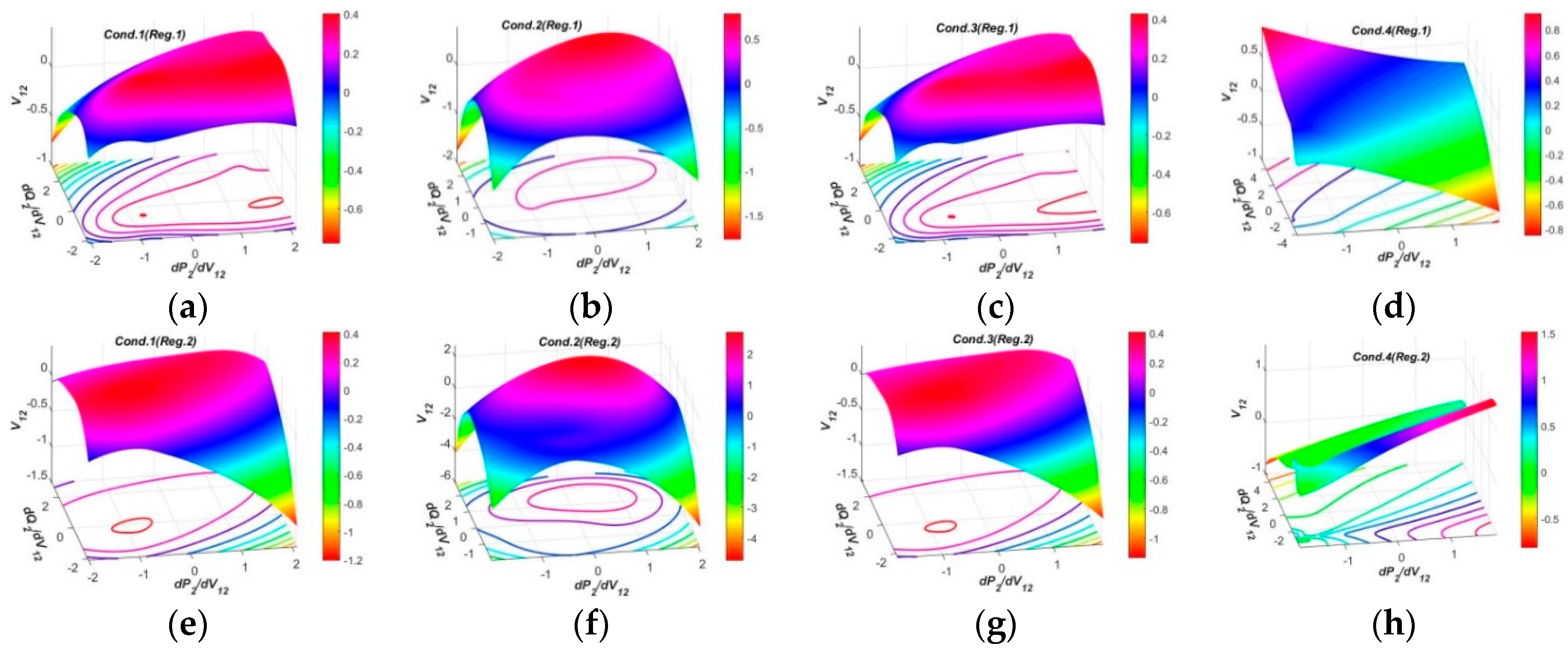
3.3.2. Test Results and Analysis in Three-Dimensional Spaces

In this section, the PFG at SCP2 will continued to be analyzed in spaces. According to Equation (4), the PFG to CIV1 are similar to that at SCP1, so it is also neglected for analysis here. In (a)–(d) of Figure 5, the PFG to CIV2 at SCP2 by Reg.1 mode present the similar spatial surfaces in the normal conditions, while the surfaces in the severe condition have larger curvatures. The PFG to CIV2 at SCP2 by Reg.2 mode present similar surface shapes, but the distribution tendencies of the surfaces are along the inverse horizontal directions to those of Reg.1. The features imply that the PFG to CIV2 can be regulated to change by inverse distribution tendencies to meet for more diverse regulation requirements of the power system.
As for the PFG to each CIV3 at SCP2 shown in Figure 6, the spatial surfaces all present similar funnel shapes, but the curvatures in regulation Scen.2, Scen.3 and Scen.4 are larger than Scen.1, indicating that when the system operation condition varies, the UPFC can perform the regulations more efficiently in regulation Scen.2, Scen.3 and Scen.4, but the requirements for suppressing the resulting shocks are more rigorous at the same time, so as to maintain the stability and normal operations of the power system.

3.4. Test Results and Analysis for PFG at SCP3

3.4.1. Test Results and Analysis in Two-Dimensional Planes

According to the theoretical analysis, the PFG at SCP3 have the most degrees of freedom for regulations and the most complicated changing rules. As shown in (a) of Figure 7, the PFG to CIV1 at SCP3 in the normal operation conditions present similar curves ranging within −2.0 p.u. to 3.0 p.u., except that the PFG in the severe condition have larger ranges to own more high regulation efficiencies. In (b) and (c) of Figure 7, the APFG and RPFG to CIV2 show similar changing rules as those at SCP2, which can also be inferred by Equations (5) and (8). In (d) of Figure 7, all the curves of PFG to CIV3 at SCP3 show nearly the same shapes, and the magnitudes and phases of the curves in different regulation scenarios have only small differences.
From another point of view, in (e) of Figure 7, the curves of APFG against RPFG to CIV1 are analogous to certain nearly closed shapes, which much different to those at SCP1 and SCP2, and can be more adaptive to different operation conditions. As for (f) of Figure 7, the curves of APFG against RPFG to CIV1 in two different operation conditions will form certain closed shapes, but the two curves in the same operation condition by Reg.1 and Reg.2 modes present similar changing rules, indicating the PFG to CIV2 can be regulated within larger overall regions and have more regulation tendencies.

3.4.2. Test Results and Analysis in Three-Dimensional Spaces

According to Equation (7) and Figure 8, the spatial surfaces of the PFG at SCP3 in spaces have vastly different shapes than the other SCPs. The surfaces by Reg.1 and Reg.2 modes all present non-uniform dome shapes humping upwards, and the surface areas by the two regulation modes are similar, and are all larger than those at SCP1 and SCP2, indicating the PFG to CIV1 at SCP3 have nearly the same regulation efficiencies which are larger than SCP1 and SCP2.
According to Equations (8) and (5) and Figure 9, the spatial surfaces of PFG to CIV2 at SCP3 are similar to those at SCP2, and the primary difference lies in that the spatial surfaces at SCP3 by Reg.2 have larger curvatures and areas than those at SCP2, indicating the OSIV of UPFC at SCP2 has enough large efficiencies to regulate the power flows at other SCP3. Another difference is that the spatial surfaces at SCP3 in the severe operation condition display non-closed loops of the projections on the P-Q planes.
The spatial surfaces of PFG to CIV3 at SCP3 in four regulation scenarios are shown in Figure 10. The prominent features are that the spatial surfaces have two funnel peaks, one humps upwards and the other one humps downwards, indicating that the PFG to CIV3 at SCP3 can have inverse varying tendencies within different regulation regions, this feature is more beneficial to occupy larger surface areas and adaptive to different regulation requirements.

3.5. Test Results and Analysis for PFG at SCP4

3.5.1. Test Results and Analysis in Two-Dimensional Planes

Based on the Equation (10), the PFG to CIV1 at SCP4 have two degrees of freedom for regulation. In (a) of Figure 11, the APFG in the normal operation conditions have the similar curves and focus within certain regions, while those of RPFG also have the similar curves and focus within other regions. Both the curves of APFG and RPFG in the severe operation condition stay at different regions with those in the normal operation conditions. In (b), (c) and (f) of Figure 11, the APFG and RPFG to CIV2 at SCP4, and the curves of APFG against RPFG to CIV2 are similar to those at SCP2 and SCP3, which can be deduced from Equations (5), (8) and (11). Similarly, according to (d) and (e) of Figure 11, the PFG to CIV3 at SCP4 have nearly the same changing rules with those at SCP3, which can also be obtained from Equations (9) and (12).

3.5.2. Test Results and Analysis in Three-Dimensional Spaces

Based on the Equations (10) and (11) and theoretical analysis, the spatial surfaces of PFG to CIV1 and CIV2 at SCP4 have similar changing rules, and the latter surfaces have one more degree of freedom. Therefore, it is just essential to choose the spatial surfaces of PFG to CIV2 for analysis. As shown in Figure 12, the spatial surfaces of PFG to CIV2 at SCP4 by Reg.1 mode still present funnel shapes in the normal operation conditions. In contrast the surfaces by Reg.1 in the severe operation condition and the surfaces by Reg.2 in all operation conditions have much larger curvatures. Moreover, the spatial surfaces of PFG to CIV2 at SCP4 by Reg.2 mode also have larger curvatures and areas than those at SCP2, revealing the OSIV of UPFC at SCP2 has enough large efficiencies to regulate the power flows at SCP4.
Based on Equations (9) and (12), the spatial surfaces of PFG to CIV3 at SCP4 are similar to those at SCP3 as shown in Figure 13. The differences mainly lie in the distribution rules of the funnel peaks and curvatures, indicating that spatial surfaces of PFG to CIV3 at SCP4 are also beneficial and adaptive to different regulation requirements.

4. Conclusions

This paper has researched and compared the regulation principles and efficiencies of the power flow gradients to multiple characteristic independent variables by multiple regulation modes and scenarios at several critical points of the UPFC embedded power system. The mathematical model of APFG and RPFG at each SCP are built based on detailed real circuit, and it was tested and analyzed in different typical operation conditions and in planes and spaces. The main conclusions are summarized as below.
(1)
The PFG to each CIV at different SCP have different degrees of freedom for regulations. The PFG at SCP1 have the fewest degrees of freedom and the simplest regulation principles for regulations by UPFC-. The PFG at SCP2 and SCP4 have the similar degrees of freedom for regulations by UPFC, and the PFG at SCP3 owns the most degrees of freedom and the most complicated regulation principles for regulations for regulations by UPFC, indicating that the PFG of the power system can be regulated by UPFC efficiently after the insertion of OSIV at SCP2.
(2)
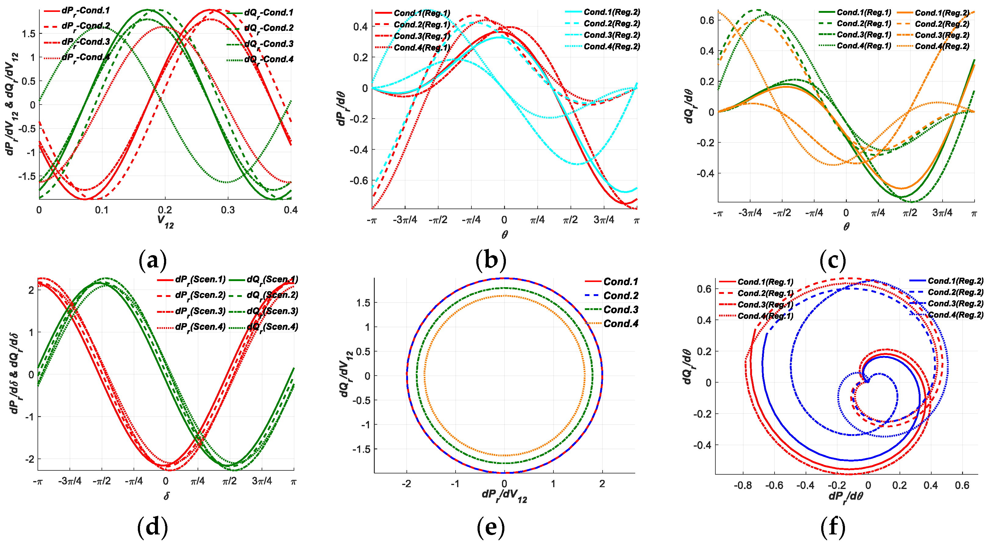
In the two-dimensional planes, the APFG and RPFG to CIV1 at SCP3 and SCP4 in the normal operation conditions have the similar curves and focus within their individual certain regions, while the curves of APFG and RPFG in the severe operation condition stay at different regions with the curves in the normal operation conditions. The PFG to CIV2 at each SCP can be regulated to larger or smaller required amplitudes in different regions by Reg.1 and Reg.2 modes, the curves of APFG to CIV2 against RPFG to CIV2 by Reg.1 and Reg.2 modes can form special axial or rotational symmetrical closed shapes, the regulation ranges and areas by Reg.2 mode in the third and fourth operation condition are much larger than others, which are beneficial to be regulated throughout an overall closed region and adaptive to different operation conditions. Both the curves of PFG to CIV3 at SCP1, SCP3 and SCP4 show nearly the same shapes with the similar magnitudes and phases in different regulation scenarios, while those at SCP2 are with different magnitudes and phases, indicating the regulations of PFG by UPFC at SCP2 can be efficiently adaptive to different operation conditions.
(3)
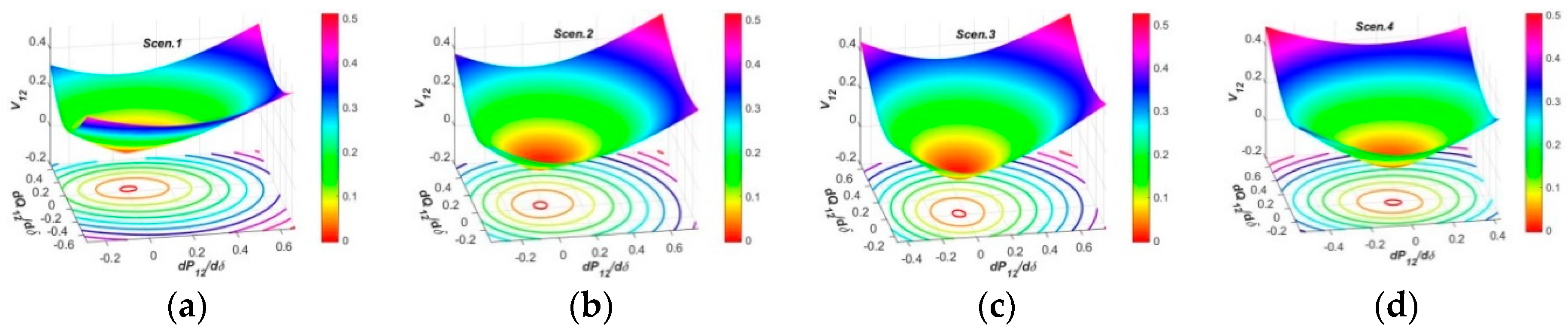
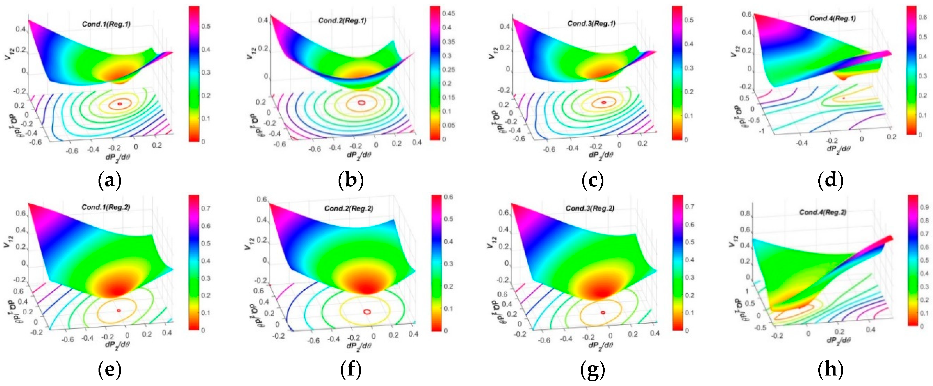
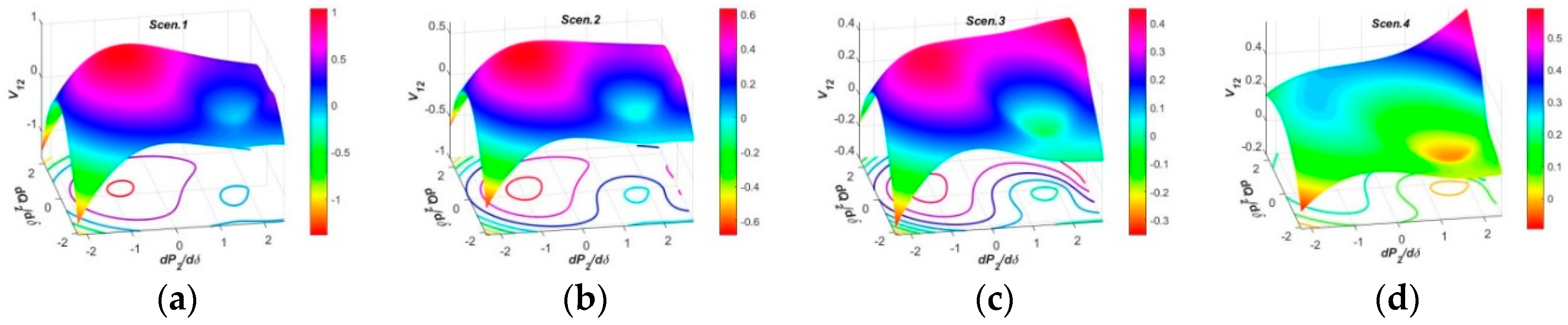
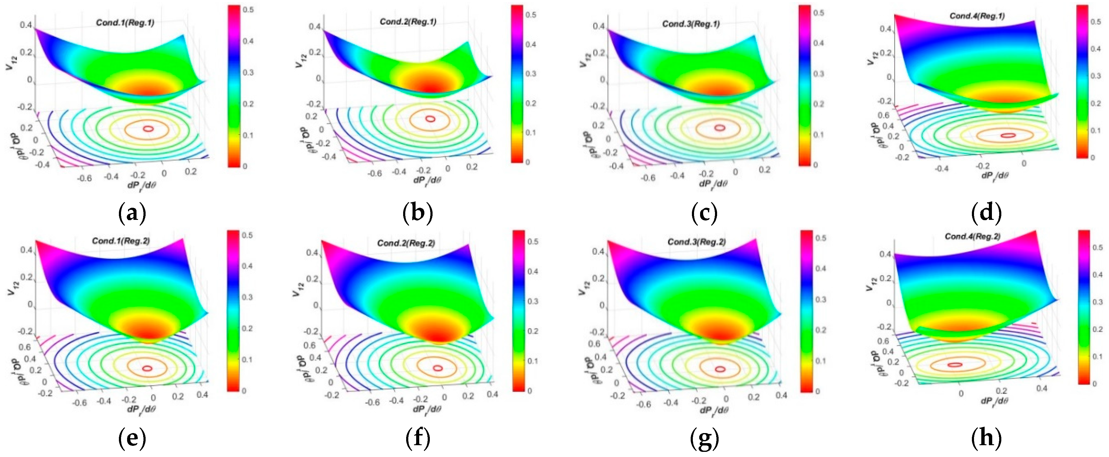
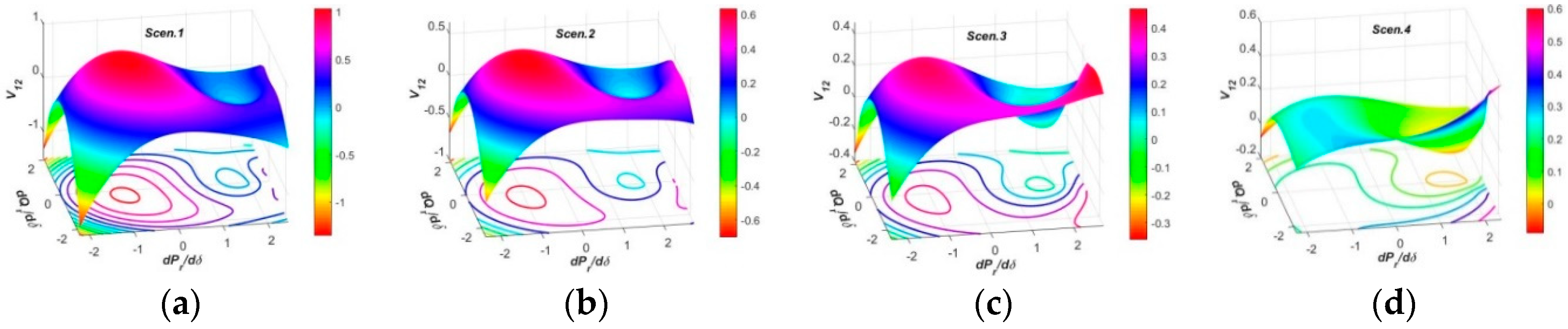
In the three-dimensional spaces, the spatial surfaces of PFG to CIV1 at SCP3 have non-uniform dome shapes humping upwards, and nearly the same regulation efficiencies by Reg.1 and Reg.2 modes which are larger than SCP1 and SCP2. The spatial surfaces of PFG to CIV2 at each SCP present similar funnel shapes in all operation conditions, and the surface curvatures and areas by Reg.1 mode at each SCP are similar, but those by Reg.2 mode at SCP1, SCP3 and SCP4 are larger than SCP2, revealing the OSIV of UPFC at SCP2 has enough large efficiencies to regulate the power flows at other SCP. The spatial surfaces of PFG to CIV3 at SCP2 present similar funnel shapes, while those at SCP3 and SCP4 have two funnel peaks and inverse varying tendencies within different regulation regions, which is more beneficial to occupy larger surface areas and adaptive to different regulation requirements.
(4)
When the PFG to CIVs have larger regulation efficiencies, the resulting impulses or shocks to the power system during the regulation processes may also be more intense, and the requirements for suppressing the resulting shocks need to be more rigorous at the same time, so as to maintain the stability and normal operations of the power system.

Author Contributions

J.L. conceived and wrote the original manuscript, Z.X. is the supervision, J.Y. reviewed and edited the paper critically, Z.Z. prepared the resources and P.S. searched literatures. All authors have read and agreed to the published version of the manuscript.

Funding

This research was funded by the Headquarters Research Projects of State Grid Corporation of China grant number SGTYHT/15-JS-191.

Conflicts of Interest

The authors declare no conflicts of interest.

Nomenclature

UPFCunified power flow controller
V1the voltage of Bus1
v2the voltage of Bus2
zrthe impendence of the receiving end transmission line
rrthe resistance of zr
I1the current through the transmission line of the system
δthe phase difference between V1 and vr
APFGactive power flow gradients
SCPselected critical points
SCP2the voltage v12 of OSIV
SCP4the voltage vr of the receiving end
CIV1the magnitude of OSIV
CIV3the phase difference δ
Reg.1the first regulations mode of OSIV
Cond.1the first normal operation condition
Cond.3the third normal operation condition
Scen.1the first regulation scenarios for CIV3
Scen.3the third regulation scenarios for CIV3
dPj/dv12the APFG to CIV1 at SCPj
dPj/the APFG to CIV1 at SCPj
OSIVoutput series inserted voltage
v12the voltage of OSIV
vrthe voltage of the receiving end
vzrthe voltage drop on the zr
xrthe reactance of zr
θthe phase angle of OSIV
RFGpower flow gradients
RPFGreactive power flow gradients
SCP1the voltage of Bus1
SCP3the voltage of Bus2
CIVscharacteristic independent variables
CIV2the phase angle θ of OSIV
jstands for the number of SCP
Reg.2the second regulations mode of OSIV
Cond.2the second normal operation condition
Cond.4the severe operation condition
Scen.2the second regulation scenarios for CIV3
Scen.4the fourth regulation scenarios for CIV3
dQj/dv12the RPFG to CIV1 at SCPj
dQj/the RPFG to CIV1 at SCPj
dPj/the RPFG to CIV1 at SCPj

Appendix A

The original mathematic model for the active and reactive power flows of the UPFC embedded power system at each SCP is listed in (A1)–(A4). For convenience, some expressions are denoted by special letters as below.
a = v r cos δ , b = v r sin δ , c = v 12 cos θ , d = v 12 sin θ , m = V 1 + c a , n = d b , z r 2 = r r 2 + x r 2 .
{ P 1 = V 1 ( r r m + x r n ) / z r 2 Q 1 = V 1 ( r r n x r m ) / z r 2
{ P 12 = [ r r ( c m + d n ) + x r ( c n d m ) ] / z r 2 Q 12 = [ r r ( c n d m ) x r ( c m + d n ) ] / z r 2
{ P 2 = [ r r ( V 1 m + c m + d n ) + x r ( V 1 n + c n d m ) ] / z r 2 Q 2 = [ r r ( V 1 n + c n d m ) x r ( V 1 m + c m + d n ) ] / z r 2
{ P r = [ r r ( a m + b n ) + x r ( a n b m ) ] / z r 2 Q r = [ r r ( a n b m ) + x r ( a m + b n ) ] / z r 2

References

  1. Gyugyi, L.; Schauder, C.D.; Williams, S.L. The unified power flow controller: A new approach to power transmission control. IEEE Trans. Power Del. 1995, 10, 1085–1097. [Google Scholar] [CrossRef] [Green Version]
  2. Bulac, C.; Eremia, M.; Balaurescu, R.; Stefanescu, V. Load flow management in the interconnected power systems using UPFC devices. In Proceedings of the IEEE Bologna Power Tech Conference, Bologna, Italy, 23–26 June 2003. [Google Scholar]
  3. Stefanov, P.C.; Stankovic, A.M. Modeling of UPFC operation under unbalanced conditions with dynamic phasors. IEEE Trans. Power Syst. 2002, 17, 395–403. [Google Scholar] [CrossRef]
  4. Mete, A.; Mehmet, T. Mathematical modeling and analysis of a unified power flow controller: A comparison of two approaches in power flow studies and effects of UPFC location. Electr. Power Energy Syst. 2007, 29, 617–629. [Google Scholar]
  5. Shahgholian, G.; Mahdavian, M.; Janghorbani, M.; Eshaghpour, I.; Ganji, E. Analysis and Simulation of UPFC in Electrical Power System for Power Flow Control. In Proceedings of the 2017 14th International Conference on Electrical Engineering/Electronics, Computer, Telecommunications and Information Technology (ECTI-CON), Phuket, Thailand, 27–30 June 2017. [Google Scholar]
  6. Hamache, A.; Bensidhoum, M.O.; Ouslimani, A. UPFC Power Flow Tracking using Decentralized Discrete-Time Quasi-Sliding Mode Control. In Proceedings of the 2019 8th International Conference on Systems and Control (ICSC), Marrakesh, Morocco, 23–25 October 2019. [Google Scholar]
  7. Ebeed, M.; Kamel, S.; Yu, J.; Jurado, F. Development of UPFC operating constraints enforcement approach for power flow control. IET Gener. Trans. Distri. 2019, 13, 4579–4591. [Google Scholar] [CrossRef]
  8. Papic, I. Mathematical analysis of FACTS devices based on a voltage source converter Part 1: Mathematical models. Electr. Power Energy Syst. 2000, 56, 139–148. [Google Scholar] [CrossRef]
  9. Parvathy, S.; Thampatty, K.S. Dynamic Modelling and Control of UPFC for Power Flow Control. Procedia Technol. 2015, 21, 581–588. [Google Scholar] [CrossRef] [Green Version]
  10. Tomasz, O.; Kazimierz, W. Consideration of Different Operation Modes of UPFC in Power System State Estimation. In Proceedings of the International Conference on Environment and Electrical Engineering, Rome, Italy, 8–11 May 2011. [Google Scholar]
  11. Nabavi, A.; Iravani, R. Steady State and Dynamic Models of UPFC for Power System Studies. IEEE Trans. Power Syst. 1996, 11, 1937–1943. [Google Scholar] [CrossRef]
  12. Marcos, P.; Luiz, C. A current based model for load flow studies with UPFC. IEEE Trans. Power Syst. 2013, 28, 677–682. [Google Scholar]
  13. Alomoush, M.I. Impacts of UPFC on line flows and transmission usage. Electr. Power Syst. Res. 2004, 71, 223–234. [Google Scholar] [CrossRef]
  14. Wu, X.; Zhou, Z.; Liu, G.; Qi, W.; Xie, Z. Preventive security-constrained optimal power flow considering UPFC control modes. Energies 2017, 10, 1199. [Google Scholar] [CrossRef] [Green Version]
  15. Abbas, R.; Mahmud, F.; Muhammad, O. Optimal unified power flow controller application to enhance total transfer capability. IET Gener. Trans. Distr. 2015, 9, 358–368. [Google Scholar]
  16. Hasan, R.; Salman, S.; Saleem, N. Control system design of UPFC for optimal power flow control. In Proceedings of the International Conference on Open Source Systems and Technologies, Lahore, Pakistan, 16–18 December 2019. [Google Scholar]
  17. Yuan, J.; Liu, L.; Fei, W. Hybrid electromagnetic unified power flow controller: A novel flexible and effective approach to control power flow. IEEE Trans. Power Deliv. 2018, 33, 2061–2069. [Google Scholar] [CrossRef]
  18. Monteiro, J.; Pinto, S.; Martin, A.D. A new real time Lyapunov based controller for power quality improvement in unified power flow controllers using direct matrix converters. Energies 2017, 10, 779. [Google Scholar] [CrossRef] [Green Version]
  19. Ilango, G.S.; Nagamani, C.; Sai, A.V.; Aravindan, D. Control algorithms for control of real and reactive power flows and power oscillation damping using UPFC. Electr. Power Syst. Res. 2009, 79, 595–605. [Google Scholar] [CrossRef]
  20. Wilson, D.G.; Robinett, R.D. Nonlinear power flow control applications to conventional generator swing equations subject to variable generation. In Proceedings of the International Symposium on Power Electronics, Pisa, Italy, 14–16 June 2010. [Google Scholar]
  21. Zahid, M.; Chen, J.; Li, Y.; Duan, X.; Lei, Q.; Bo, W.; Mohy, G.; Waqar, A. New approach for optimal location and parameters setting of UPFC for enhancing power systems stability under contingency analysis. Energies 2017, 10, 1738. [Google Scholar] [CrossRef] [Green Version]
  22. Liu, J.; Xu, Z.; Xiao, L. Comprehensive power flow analyses and novel feedforward coordination control strategy for MMC-Based UPFC. Energies 2019, 12, 824. [Google Scholar] [CrossRef] [Green Version]
Figure 1. The structure and phasor diagrams of the unified power flow controller (UPFC): (a) Schematic diagram of the UPFC embedded system; (b) Phasor diagram of the UPFC embedded system.
Applsci 10 01720 g001
Figure 2. Curves of power flow gradients (PFG) to each characteristic independent variable (CIV) at SCP1 in planes: (a) Curves of the PFG to CIV1; (b) Curves of the PFG to CIV2. (c) Curves of the PFG to CIV3; (d) Curves of active power flow gradients (APFG) against reactive power flow gradients (RPFG) to CIV1; (e) Curves of APFG against RPFG to CIV2; (f) Curves of APFG against RPFG to CIV3.
Applsci 10 01720 g002
Figure 3. Spatial surfaces of PFG to CIV2 at SCP1 in spaces: (ad) Spatial surfaces of PFG to CIV2 by Reg.1 mode of output series inserted voltage (OSIV) in four operation conditions; (eh) Spatial surfaces of PFG to CIV2 by Reg.2 mode of OSIV in four operation conditions.
Applsci 10 01720 g003
Figure 4. Curves of PFG to each CIV at SCP2 in planes: (a) Curves of the PFG to CIV1; (b) Curves of the APFG to CIV2. (c) Curves of the RPFG to CIV2; (d) Curves of APFG and RPFG to CIV3; (e) Curves of APFG against RPFG to CIV2; (f) Curves of APFG against RPFG to CIV3.
Applsci 10 01720 g004
Figure 5. Spatial surfaces of PFG to CIV2 at SCP2 in spaces: (ad) Spatial surfaces of PFG to CIV2 by Reg.1 mode of OSIV in four operation conditions; (eh) Spatial surfaces of PFG to CIV2 by Reg.2 mode of OSIV in four operation conditions.
Applsci 10 01720 g005
Figure 6. Spatial surfaces of PFG to CIV3 at SCP2 in spaces: (ad) Spatial surfaces of PFG to CIV3 in four regulation scenarios.
Applsci 10 01720 g006
Figure 7. Curves of PFG to each CIV at SCP3 in planes: (a) Curves of the PFG to CIV1; (b) Curves of the APFG to CIV2. (c) Curves of the RPFG to CIV2; (d) Curves of APFG and RPFG to CIV3; (e) Curves of APFG against RPFG to CIV1; (f) Curves of APFG against RPFG to CIV2.
Applsci 10 01720 g007
Figure 8. Spatial surfaces of PFG to CIV1 at SCP3 in spaces: (ad) Spatial surfaces of PFG to CIV1 by Reg.1 mode of OSIV in four operation conditions; (eh) Spatial surfaces of PFG to CIV1 by Reg.2 mode of OSIV in four operation conditions.
Applsci 10 01720 g008
Figure 9. Spatial surfaces of PFG to CIV2 at SCP3 in spaces: (ad) Spatial surfaces of PFG to CIV2 by Reg.1 of OSIV in four operation conditions; (eh) Spatial surfaces of PFG to CIV2 by Reg.2 of OSIV in four operation conditions.
Applsci 10 01720 g009
Figure 10. Spatial surfaces of PFG to CIV2 at SCP2 in spaces: (ad) Spatial surfaces of PFG to CIV2 in four regulation scenarios.
Applsci 10 01720 g010
Figure 11. Curves of PFG to each CIV at SCP4 in planes: (a) Curves of the PFG to CIV1; (b) Curves of the APFG to CIV2; (c) Curves of the RPFG to CIV2; (d) Curves of APFG and RPFG to CIV3; (e) Curves of APFG against RPFG to CIV1; (f) Curves of APFG against RPFG to CIV2.
Applsci 10 01720 g011
Figure 12. Spatial surfaces of PFG to CIV2 at SCP4 in spaces: (ad) Spatial surfaces of PFG to CIV2 by Reg.1 mode of OSIV in four operation conditions; (eh) Spatial surfaces of PFG to CIV2 by Reg.2 mode of OSIV in four operation conditions.
Applsci 10 01720 g012
Figure 13. Spatial surfaces of PFG to CIV2 at SCP4 in spaces: (ad) Spatial surfaces of PFG to CIV2 in four regulation scenarios.
Applsci 10 01720 g013
Table 1. Typical system operation conditions in case study.
ConditionsVoltage VrPhase Difference δMagnitude of v12Phase Angle θ
Cond.11−π/80 p.u. to 4.0 p.u.−π to π
Cond.21−π/24
Cond.30.9−π/8
Cond.40.82−π/2
Table 2. Typical regulation scenarios for CIV3 in case study.
Scenariosphase Angle θMagnitude of v12Phase Difference δ
Scen.1−π/30 p.u. to 4.0 p.u.−π to π
Scen.2−π/8
Scen.3π/8
Scen.4π/3

