Design and Analysis of Novel Low-Cost Linear Vibration Motor for an Electronic Cigarette


Abstract
:Featured Application
Abstract
1. Introduction
2. Model Description
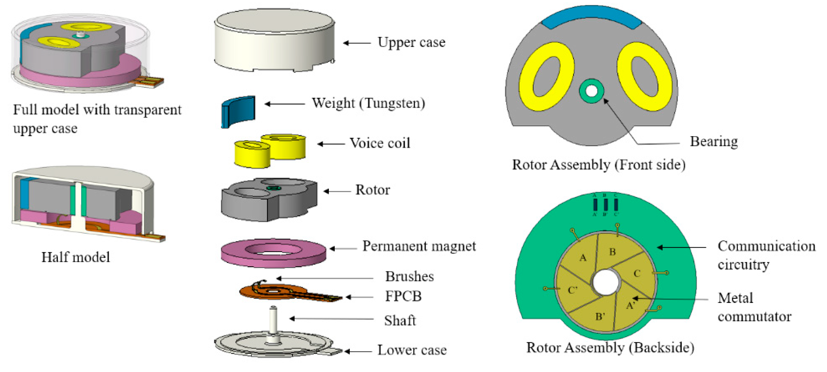
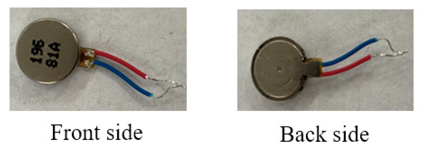
2.1. Coin-Type Vibration Motor
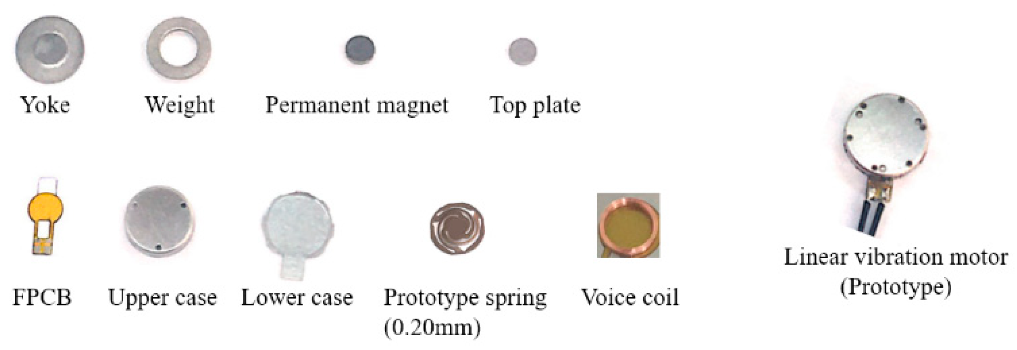
2.2. Linear Vibration Motor
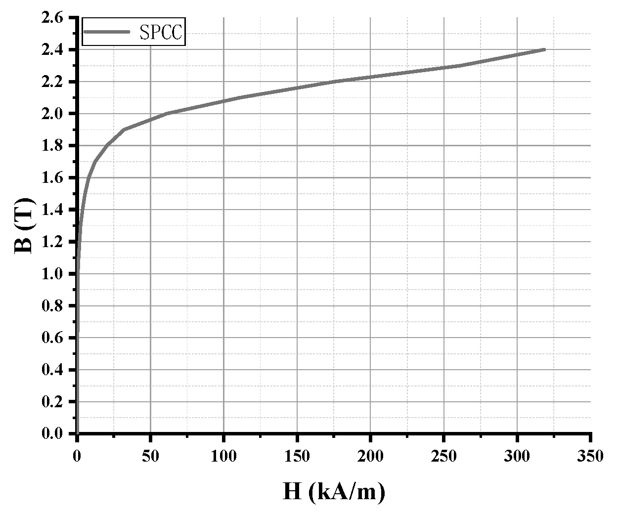
2.3. Material Properties
3. Analysis Methods
3.1. Magnetostatic Analysis
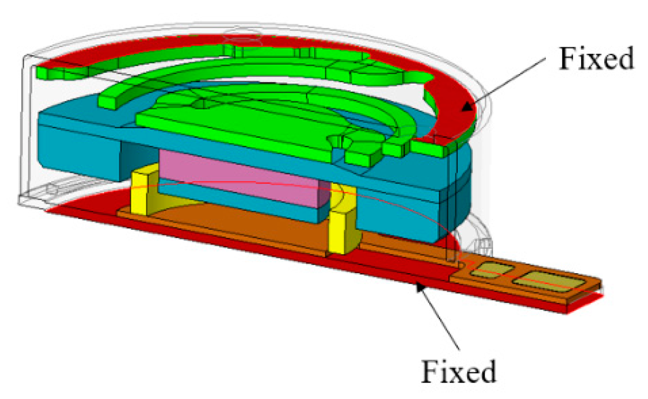
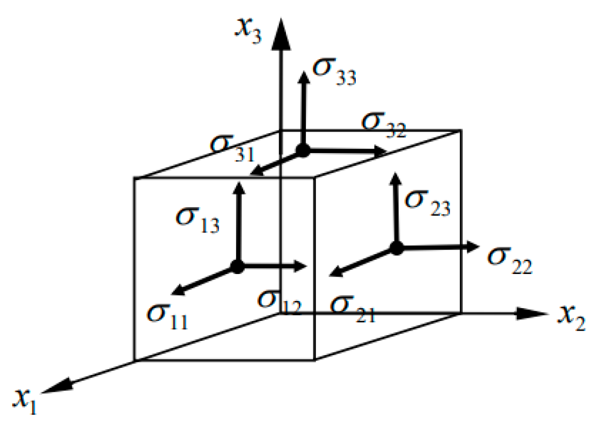
3.2. Mechanical Analysis
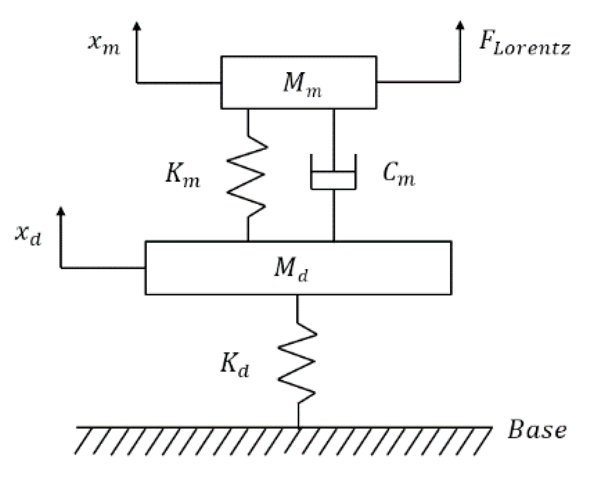
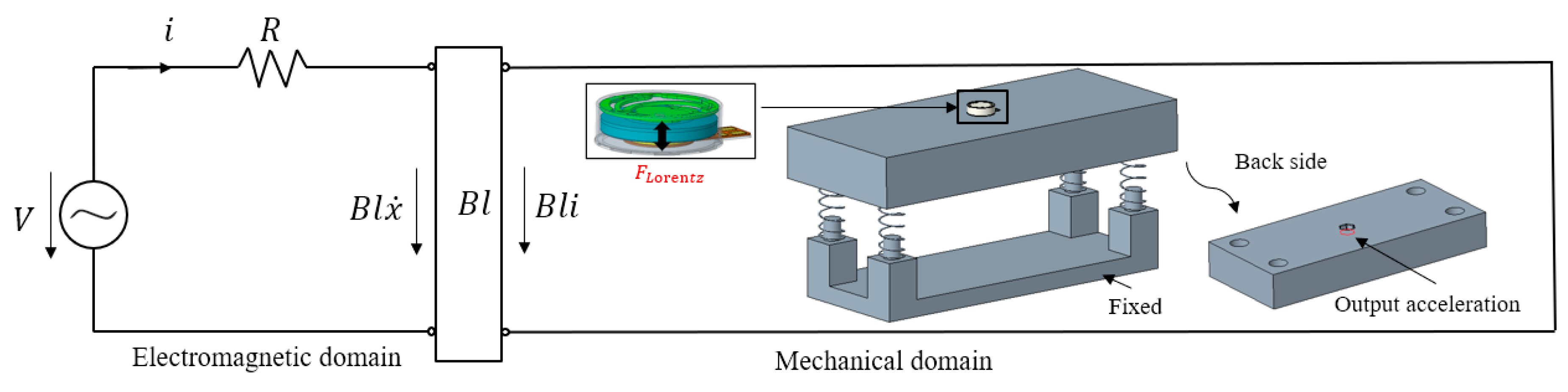
3.3. Electromagnetic-Mechanical Coupling Method
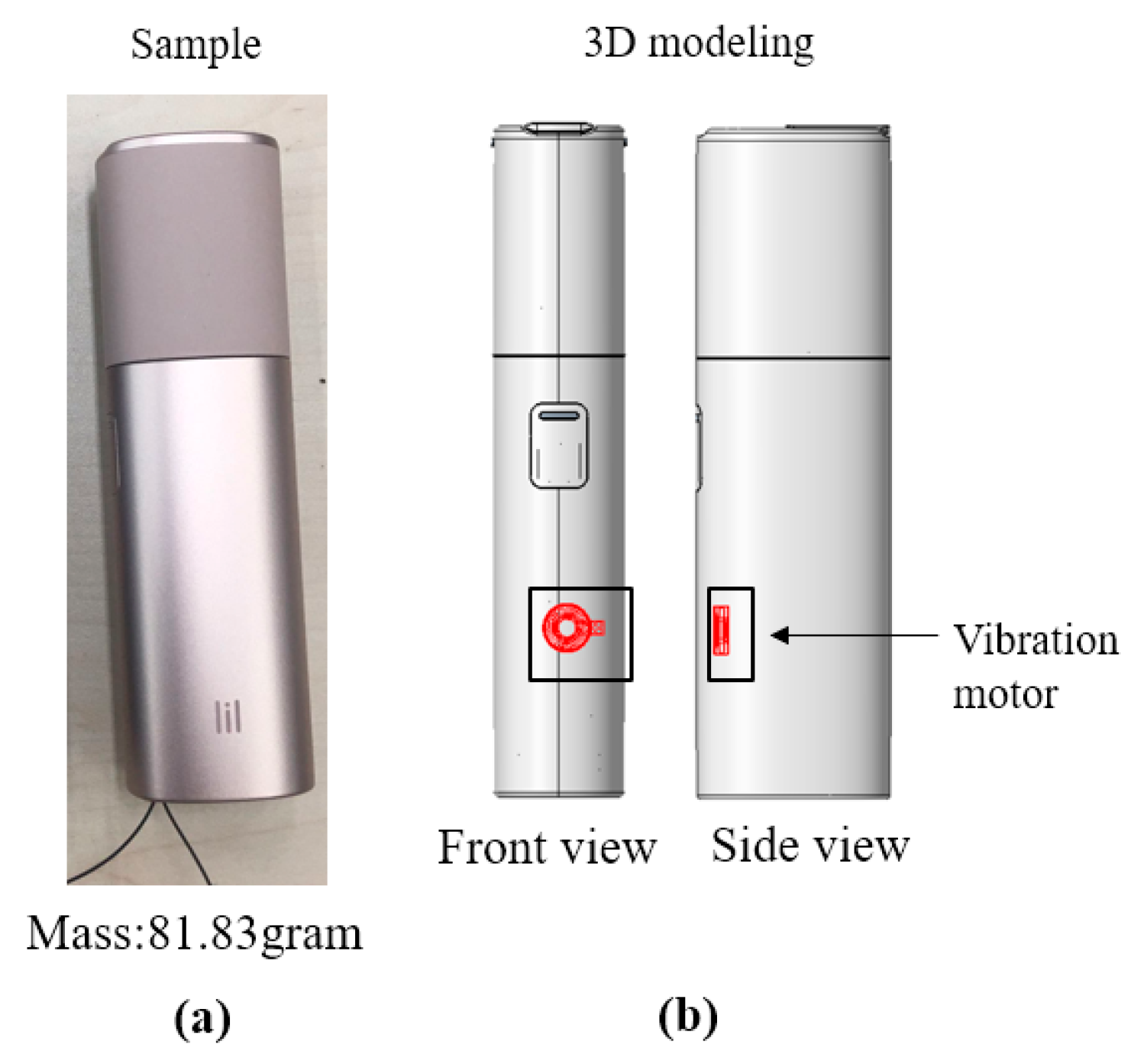
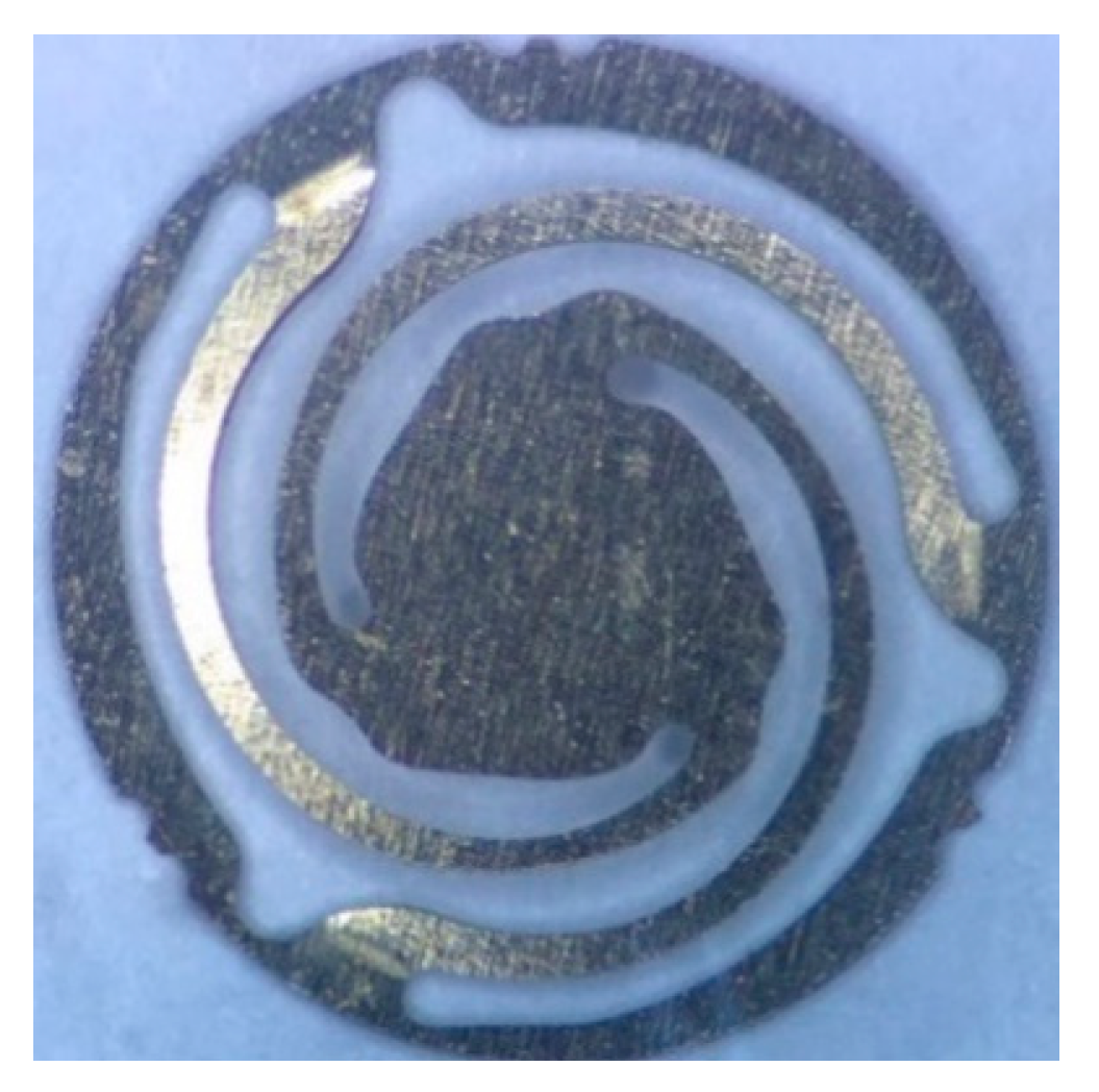
3.4. Samples
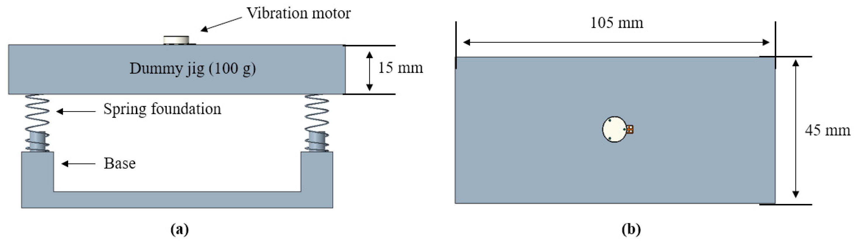
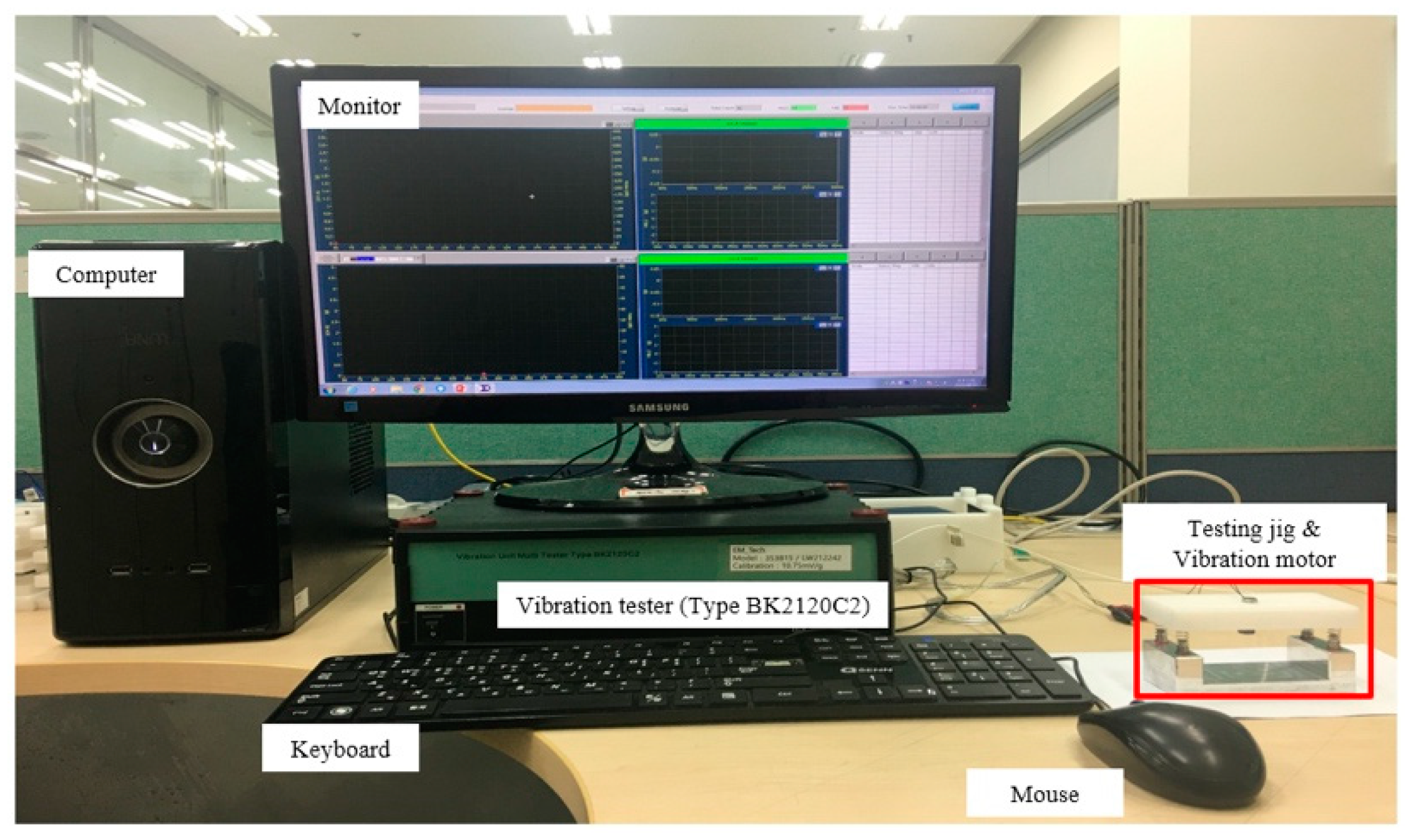
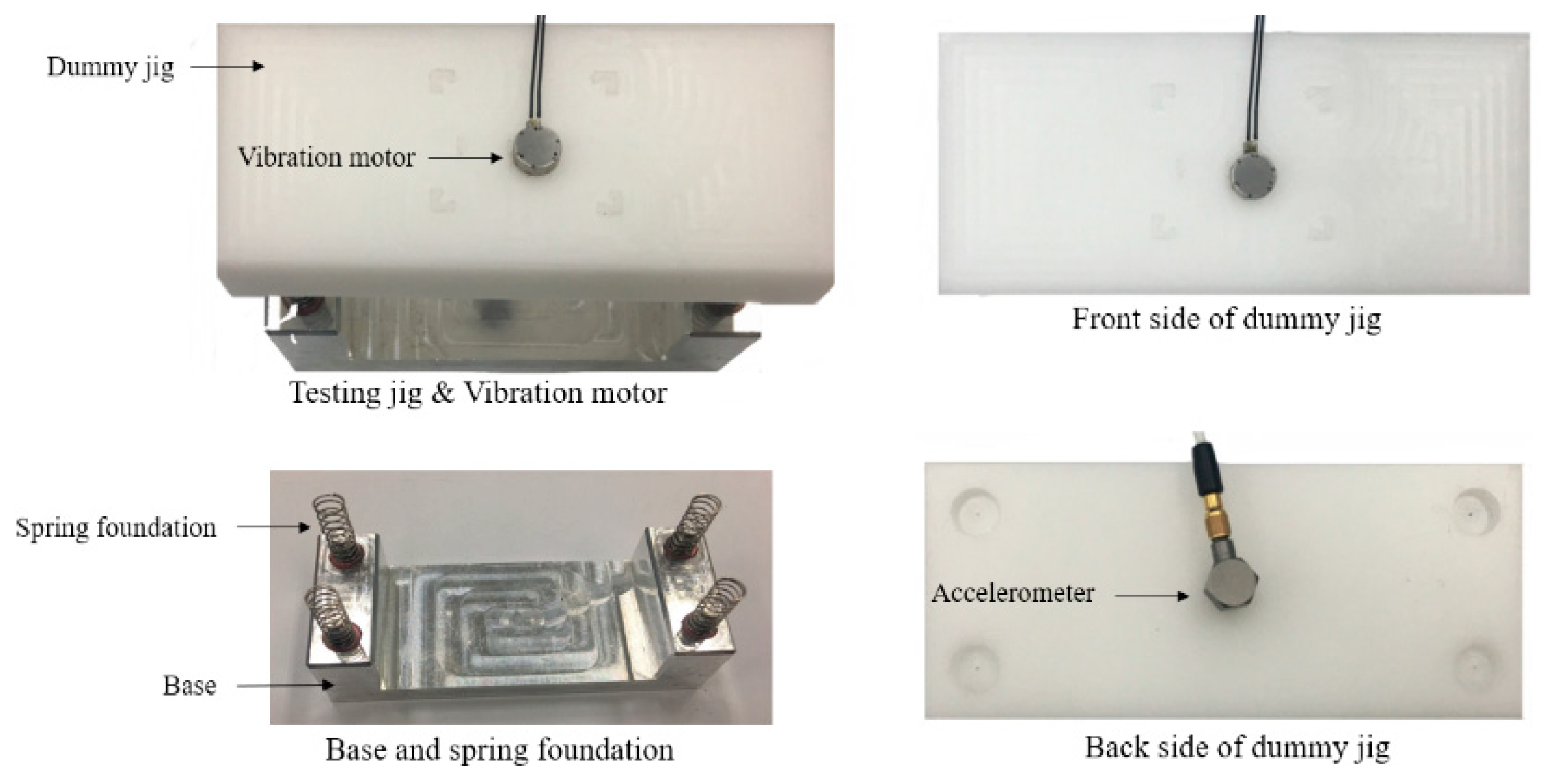
3.5. Experimental Setup
4. Design and Optimization
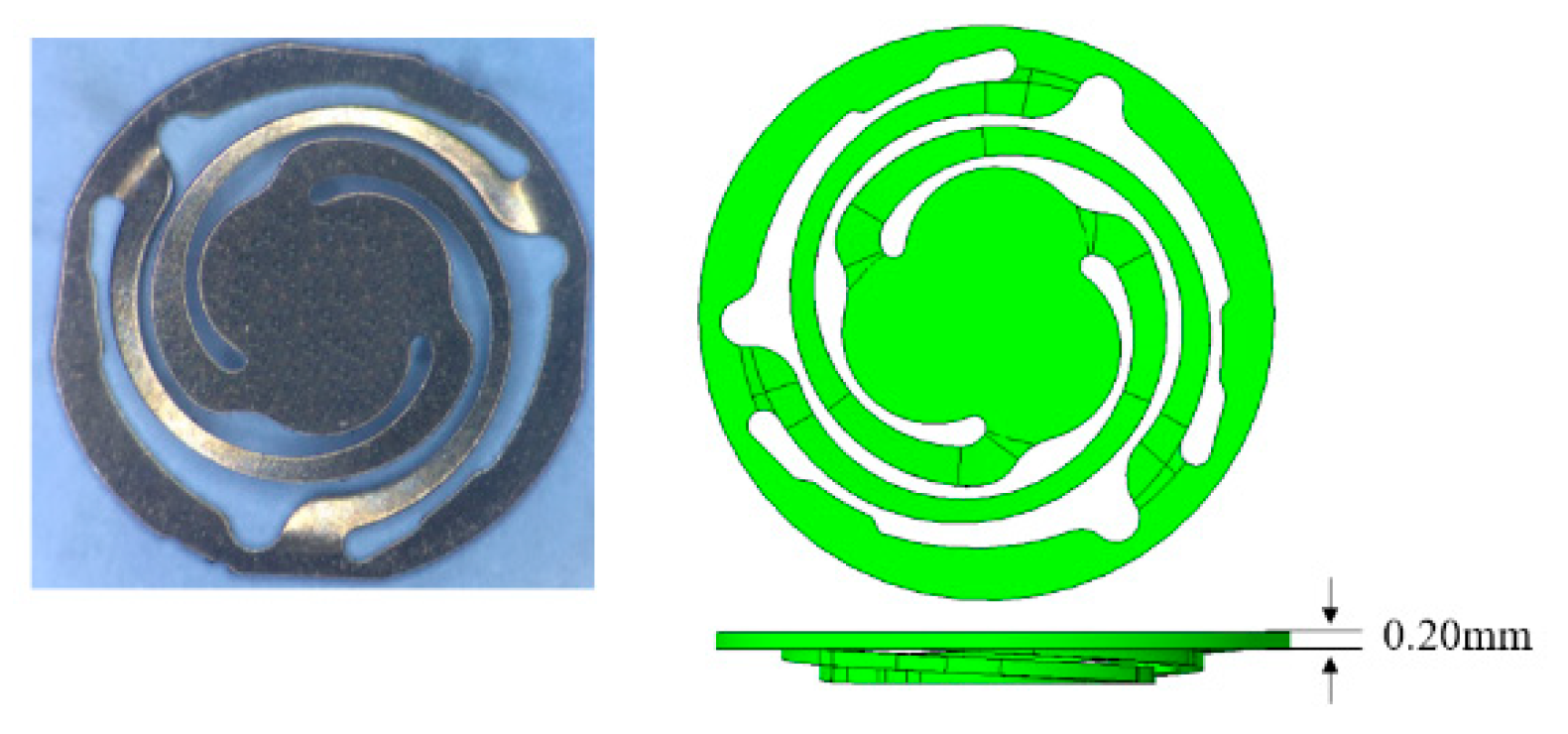
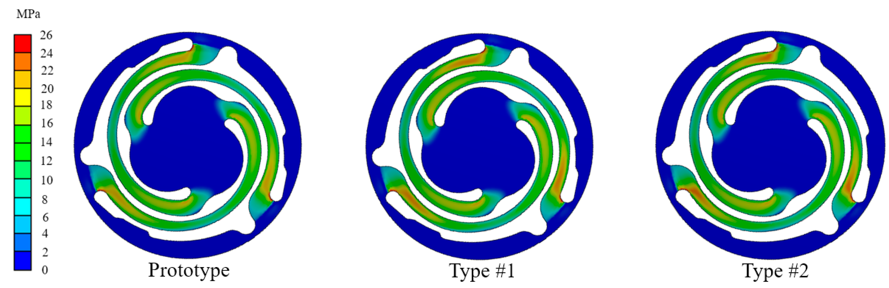
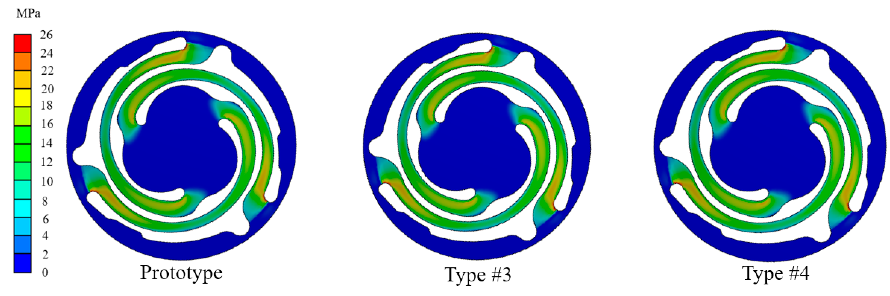
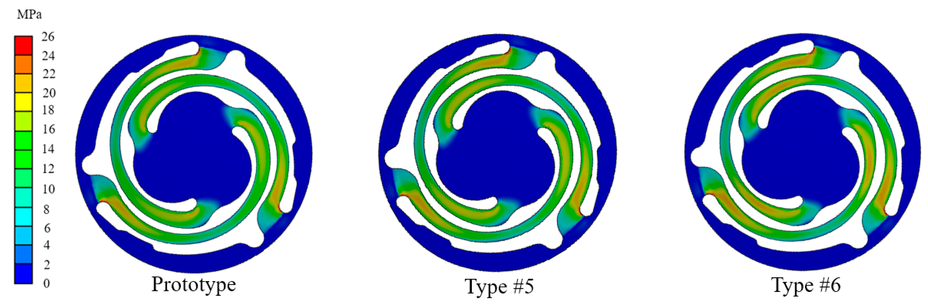
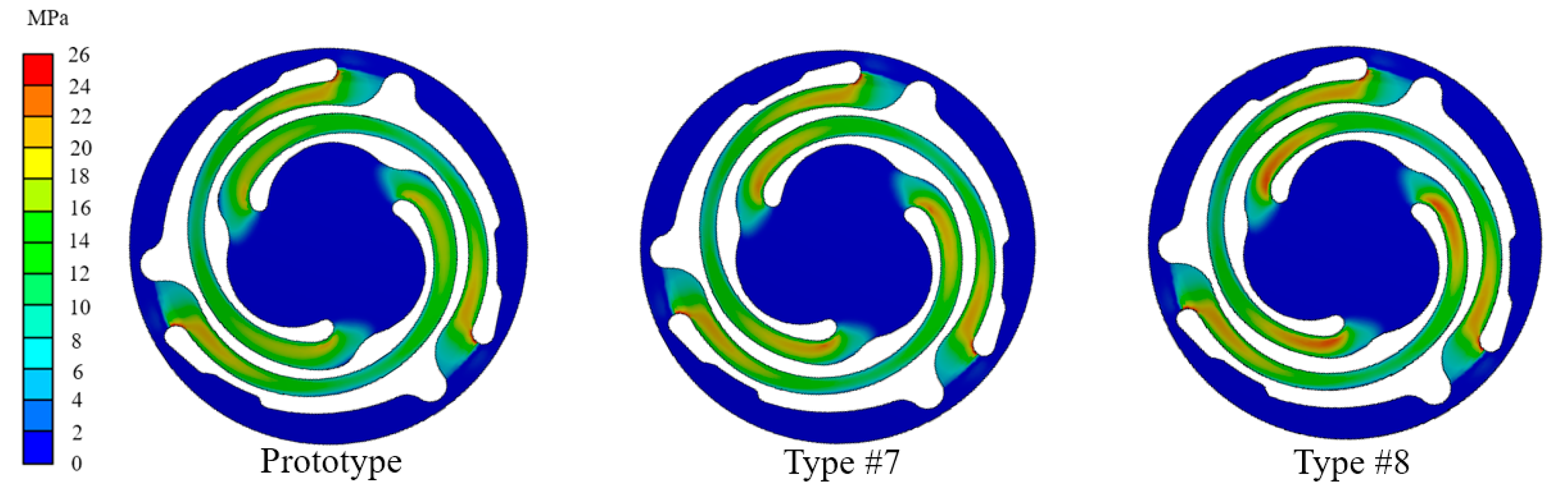
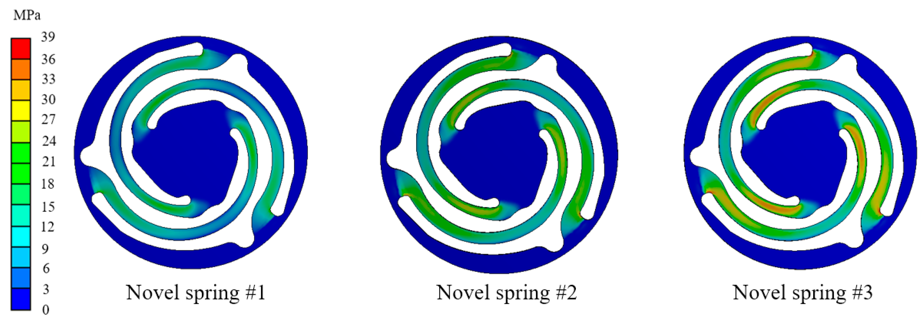
4.1. Spring Shape Designs
4.2. Spring Thickness Design
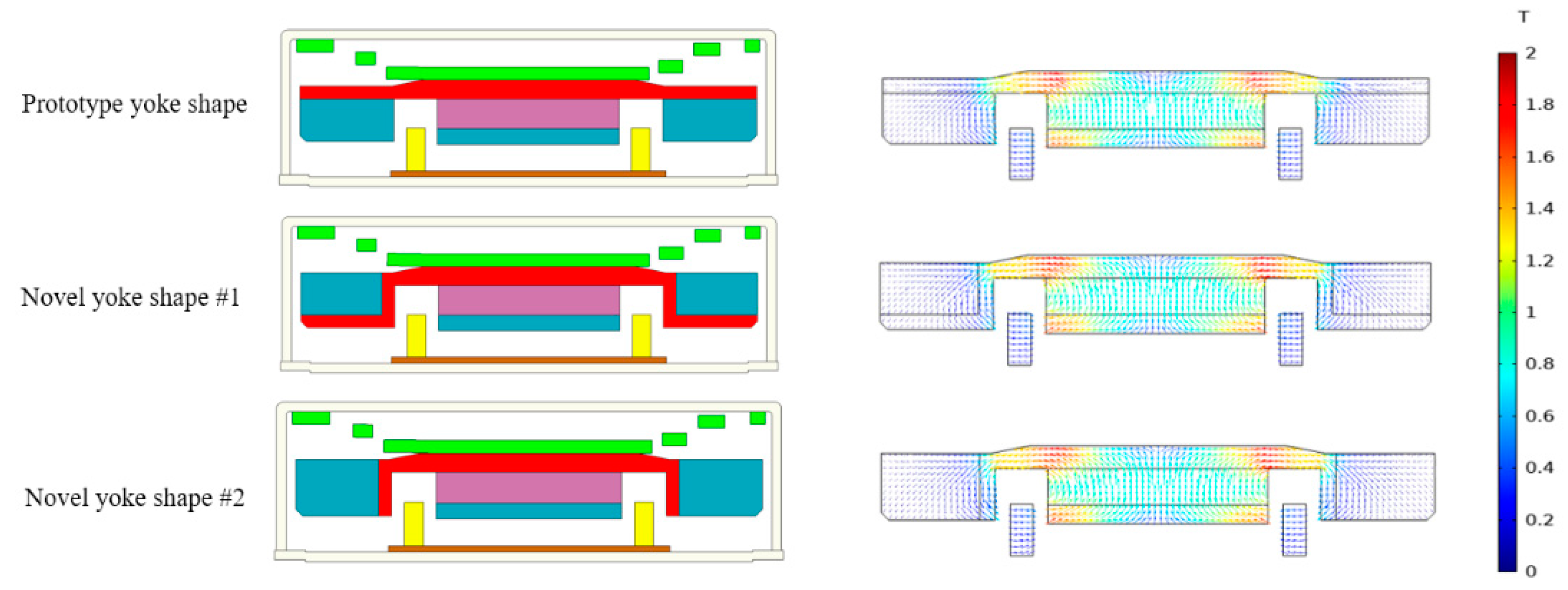
4.3. Yoke Shape Design
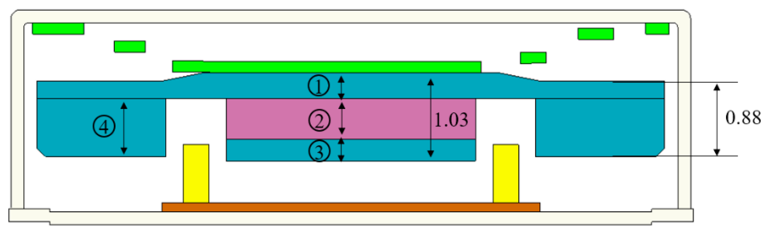
4.4. Magnetic Circuit Optimization
5. Results and Discussion
5.1. Novel Vibration Motor Samples and Experiments
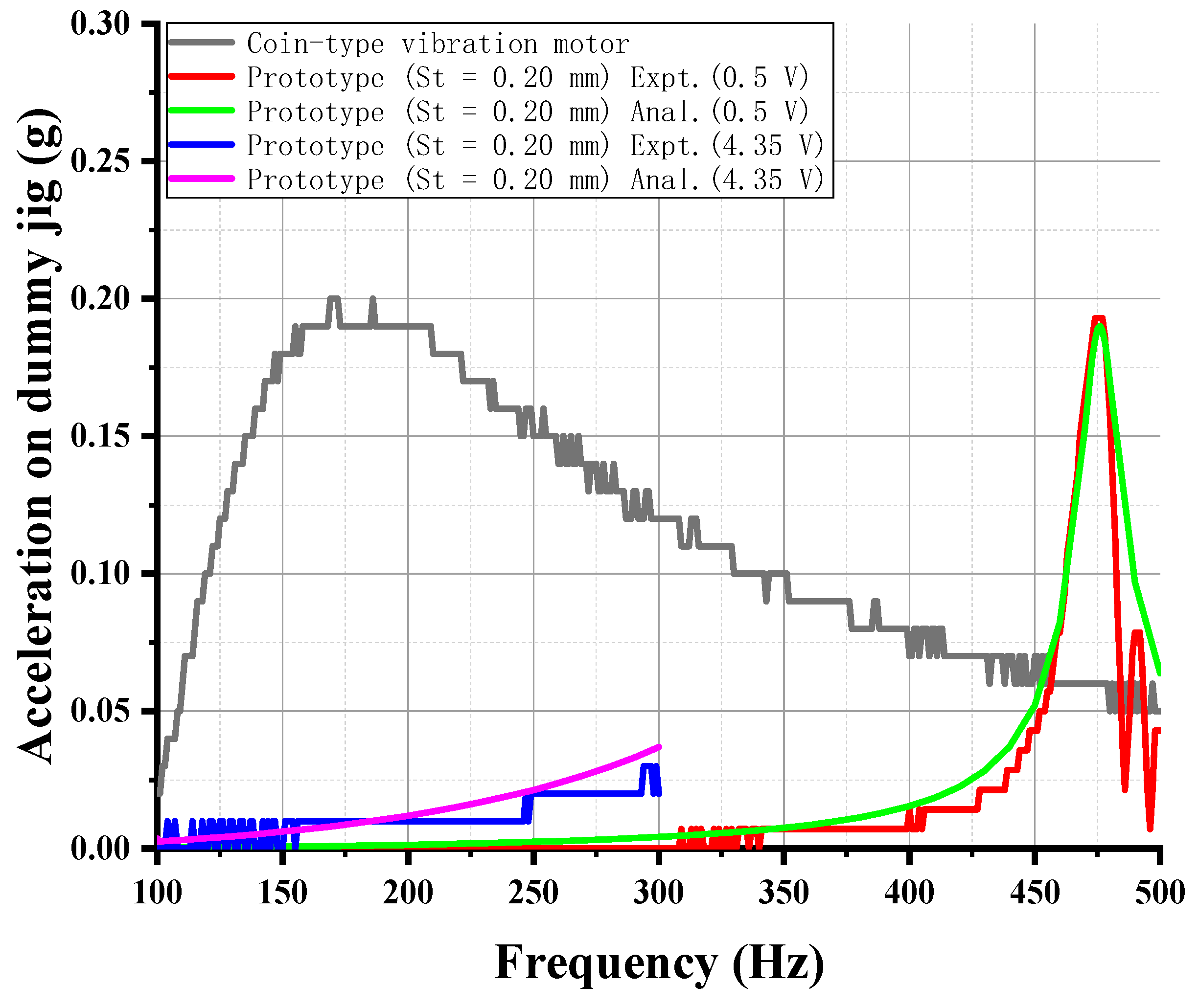
5.2. Result Comparison
6. Conclusions
Author Contributions
Funding
Conflicts of Interest
References
- Etter, J.-F. Electronic cigarettes: A survey of users. BMC Public Health 2010, 10, 23. [Google Scholar] [CrossRef] [PubMed]
- Hwang, S.-M. Development of Solenoid-Type Vibrators Used for Mobile Phones. IEEE Trans. Magn. 2003, 39, 3262–3264. [Google Scholar] [CrossRef]
- Lee, K.B.; Kim, J.H. Horizontal linear vibrating actuator to reduce smart phone thickness. J. Vibroeng. 2013, 15, 2003–2011. [Google Scholar]
- Nam, J.; Yeon, T.; Jang, G. Development of a linear vibration motor with fast response time for mobile phones. Microsyst. Technol. 2014, 20, 1505–1510. [Google Scholar] [CrossRef]
- Jiang, Z.-X.; Park, K.H.; Kim, J.-H.; Jiang, Y.-W.; Xu, D.-P.; Hwang, S.M. Analysis and Design of a New Linear Vibration Motor Used to Reduce Magnetic Flux Leakage in In-Vehicle Infotainment. Appl. Sci. 2020, 10, 3370. [Google Scholar] [CrossRef]
- Monk, P. Finite Element Methods for Maxwell’s Equations; Oxford University Press: Oxford, UK, 2003. [Google Scholar]
- Jin, J.M. The Finite Element Method in Electromagnetics; John Wiley & Sons: Hoboken, NJ, USA, 2015. [Google Scholar]
- Hughes, T.J. The Finite Element Method: Linear Static and Dynamic Finite Element Analysis; Courier Corporation: Chelmsford, MA, USA, 2012. [Google Scholar]
- Young, W.C.; Budynas, R.G.; Sadegh, A.M. Roark’s Formulas for Stress and Strain; McGraw-Hill: New York, NY, USA, 2002. [Google Scholar]
- Griffiths, D.J. Introduction to Electrodynamics; Pearson: London, UK, 2005; p. 574. [Google Scholar]
- French, A.S.; Torkkeli, P.H.; Squire, L.R. Reference module in neuroscience and biobehavioral psychology. In LR Squire. Encyclopedia of Neuroscience; Academic Press: San Diego, CA, USA, 2009; pp. 689–695. [Google Scholar]
- Barlow, S.M.; Custead, R. Vibrography: Single-Interval Up/Down (SIUD) Adaptive Vibrotactile Threshold Estimation of the Glabrous Hand and Perioral Face in Neurotypical Adults. Biomed. J. Sci. Tech. Res. 2019, 22, 16837–16847. [Google Scholar] [CrossRef] [Green Version]
- Verrillo, R.T. Vibration sensation in humans. Music Percept. 1992, 9, 281–302. [Google Scholar] [CrossRef]


| Parts | Material | Density (kg/m3) | Young’s Modulus (GPa) | Poisson’s Ratio |
|---|---|---|---|---|
| Upper case | SUS 304 | 7850 | 193 | 0.25 |
| Spring | SUS 301 EH | 7800 | 110 | 0.28 |
| Yoke/Top plate | SPCC | 7830 | 207 | 0.29 |
| Permanent magnet | Neodymium | 7010 | 160 | 0.30 |
| Voice coil | Copper | 5321 | 126 | 0.34 |
| Dummy jig | Polyoxymethylene | 1417 | 3.15 | 0.30 |
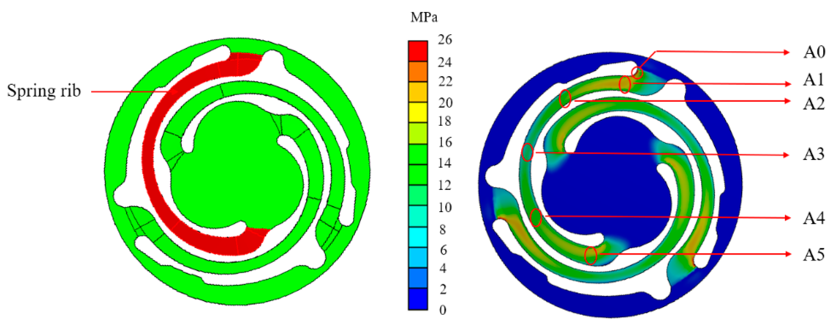
| Areas | von Mises Stress (MPa) |
|---|---|
| A0 | 25.50 |
| A1 | 22.03 |
| A2 | 17.31 |
| A3 | 10.62 |
| A4 | 16.14 |
| A5 | 20.28 |
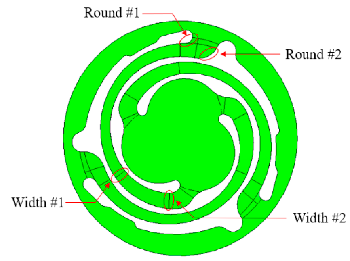
| Items | Prototype | Type #1 | Type #2 |
|---|---|---|---|
| Round #1 parameters (mm) | 0.24 | 0.26 | 0.28 |
| Maximum von Mises stress (MPa) | 25.50 | 25.76 (+1.02%) | 25.91 (+1.61%) |
| von Mises stress at A1 (MPa) | 22.03 | 23.48 (+6.58%) | 24.65 (+11.89%) |
| Resonance frequency (Hz) | 476.18 | 470.92 (−1.10%) | 463.25 (−2.72%) |
| Displacement at top plate (µm) | 25.87 | 26.45 (+2.24%) | 27.34 (+5.68%) |
| Items | Prototype | Type #3 | Type #4 |
|---|---|---|---|
| Round #2 parameters (mm) | 0.65 | 0.85 | 1.05 |
| Maximum von Mises stress (MPa) | 25.50 | 25.55 (+0.20%) | 25.61 (+0.43%) |
| von Mises stress on A1 (MPa) | 22.03 | 22.17 (+0.64%) | 22.21 (+0.82%) |
| Resonance frequency (Hz) | 476.18 | 474.85 (−0.28%) | 473.52 (−0.56%) |
| Displacement at top plate (µm) | 25.87 | 26.02 (+1.28%) | 26.16 (+1.12%) |
| Items | Prototype | Type #5 | Type #6 |
|---|---|---|---|
| Width #1 parameters (mm) | 0.40 | 0.35 | 0.30 |
| Maximum von Mises stress (MPa) | 25.50 | 25.68 (+0.71%) | 25.83 (+1.29%) |
| von Mises stress on A4 (MPa) | 16.14 | 18.53 (+14.81%) | 20.30 (+25.77%) |
| Resonance frequency (Hz) | 476.18 | 468.70 (−1.57%) | 464.32 (−2.49%) |
| Displacement at top plate (µm) | 25.87 | 26.71 (+3.25%) | 27.21 (+5.18%) |
| Items | Prototype | Type #7 | Type #8 |
|---|---|---|---|
| Width #2 parameters (mm) | 0.50 | 0.45 | 0.40 |
| Maximum von Mises stress (MPa) | 25.50 | 25.70 (+0.78%) | 25.88 (+1.49%) |
| von Mises stress on A5 (MPa) | 20.28 | 22.37 (+10.31%) | 24.62 (+21.40%) |
| Resonance frequency (Hz) | 476.18 | 467.02 (−1.92%) | 460.35 (−3.32%) |
| Displacement at top plate (µm) | 25.87 | 26.90 (+3.98%) | 27.68 (+7.00%) |
| Items | Prototype (St = 0.20 mm) | Novel Spring #1 (St = 0.20 mm) |
|---|---|---|
| Maximum von Mises stress (MPa) | 25.50 | 25.98 (+1.88%) |
| Resonance frequency (Hz) | 476.18 | 455.36 (−4.37%) |
| Displacement at top plate (µm) | 25.87 | 28.29 (+9.35%) |
| Items | Novel Spring #1 (St = 0.20 mm) | Novel Spring #2 (St = 0.15 mm) | Novel Spring #3 (St = 0.13 mm) |
|---|---|---|---|
| Maximum von Mises stress (MPa) | 25.98 | 30.73 (+18.28%) | 34.12 (+31.33%) |
| Resonance frequency (Hz) | 455.36 | 335.01 (−26.43%) | 280.38 (−38.43%) |
| Displacement at top plate (µm) | 28.29 | 52.27 (+84.76%) | 74.63 (+163.80%) |
| Types | Yoke ① | Magnet ② | Top Plate ③ | Weight ④ |
|---|---|---|---|---|
| Novel type#3 | 0.30 | 0.48 | 0.25 | 0.68 |
| MCO #1 (MG decrease) | 0.30 | 0.43 | 0.30 | 0.68 |
| MCO #2 (MG increase) | 0.30 | 0.53 | 0.20 | 0.68 |
| MCO #3 (T/P decrease) | 0.35 | 0.48 | 0.20 | 0.63 |
| MCO #4 (T/P increase) | 0.25 | 0.48 | 0.30 | 0.73 |
| MCO #5 (YK decrease) | 0.25 | 0.53 | 0.25 | 0.73 |
| MCO #6 (YK increase) | 0.35 | 0.43 | 0.25 | 0.63 |
| Types | Average Flux Density (T) | Force Factor (N/A) | Lorentz Force (N) |
|---|---|---|---|
| Novel type #3 | 0.261 | 0.388 | 0.056 |
| MCO #1 (MG decrease) | 0.245 | 0.365 | 0.053 (−5.36%) |
| MCO #2 (MG increase) | 0.273 | 0.407 | 0.059 (+5.36%) |
| MCO #3 (T/P decrease) | 0.252 | 0.375 | 0.054 (−3.57%) |
| MCO #4 (T/P increase) | 0.268 | 0.399 | 0.058 (+3.57%) |
| MCO #5 (YK decrease) | 0.262 | 0.390 | 0.057 (+1.79%) |
| MCO #6 (YK increase) | 0.261 | 0.388 | 0.056 |
| Items | Coin-Type Vibration Motor | Linear Vibration Motor |
|---|---|---|
| Dimension (mm) | Ø 8.0 × 2.75 t | Ø 8.0 × 2.50 t |
| Contact type | Pad type | |
| Rated voltage (V) | 3.0 | 4.35 |
| Resistance (Ohm) | 30.0 | 30.0 |
| Resonance frequency (Hz) | 170 | 280 |
| Input frequency (Hz) | Around 250 Hz | |
| Acceleration @ 250 Hz (G) | 0.15 | 0.21 |
| Manufacturing costs | $0.52 | $0.10 |
Publisher’s Note: MDPI stays neutral with regard to jurisdictional claims in published maps and institutional affiliations. |
© 2020 by the authors. Licensee MDPI, Basel, Switzerland. This article is an open access article distributed under the terms and conditions of the Creative Commons Attribution (CC BY) license (http://creativecommons.org/licenses/by/4.0/).
Share and Cite
Jiang, Z.-X.; Park, K.-H.; Hwang, S.-M. Design and Analysis of Novel Low-Cost Linear Vibration Motor for an Electronic Cigarette. Appl. Sci. 2020, 10, 8915. https://doi.org/10.3390/app10248915
Jiang Z-X, Park K-H, Hwang S-M. Design and Analysis of Novel Low-Cost Linear Vibration Motor for an Electronic Cigarette. Applied Sciences. 2020; 10(24):8915. https://doi.org/10.3390/app10248915
Chicago/Turabian StyleJiang, Zhi-Xiong, Ki-Hong Park, and Sang-Moon Hwang. 2020. "Design and Analysis of Novel Low-Cost Linear Vibration Motor for an Electronic Cigarette" Applied Sciences 10, no. 24: 8915. https://doi.org/10.3390/app10248915